EP2645180A2 - Electromagnetic induction heating type fixing device and image forming apparatus equipped therewith - Google Patents
Electromagnetic induction heating type fixing device and image forming apparatus equipped therewith Download PDFInfo
- Publication number
- EP2645180A2 EP2645180A2 EP13161760.7A EP13161760A EP2645180A2 EP 2645180 A2 EP2645180 A2 EP 2645180A2 EP 13161760 A EP13161760 A EP 13161760A EP 2645180 A2 EP2645180 A2 EP 2645180A2
- Authority
- EP
- European Patent Office
- Prior art keywords
- temperature
- fixing
- recording medium
- coil
- core
- Prior art date
- Legal status (The legal status is an assumption and is not a legal conclusion. Google has not performed a legal analysis and makes no representation as to the accuracy of the status listed.)
- Granted
Links
Images




Classifications
-
- G—PHYSICS
- G03—PHOTOGRAPHY; CINEMATOGRAPHY; ANALOGOUS TECHNIQUES USING WAVES OTHER THAN OPTICAL WAVES; ELECTROGRAPHY; HOLOGRAPHY
- G03G—ELECTROGRAPHY; ELECTROPHOTOGRAPHY; MAGNETOGRAPHY
- G03G15/00—Apparatus for electrographic processes using a charge pattern
- G03G15/20—Apparatus for electrographic processes using a charge pattern for fixing, e.g. by using heat
- G03G15/2003—Apparatus for electrographic processes using a charge pattern for fixing, e.g. by using heat using heat
- G03G15/2014—Apparatus for electrographic processes using a charge pattern for fixing, e.g. by using heat using heat using contact heat
- G03G15/2039—Apparatus for electrographic processes using a charge pattern for fixing, e.g. by using heat using heat using contact heat with means for controlling the fixing temperature
-
- G—PHYSICS
- G03—PHOTOGRAPHY; CINEMATOGRAPHY; ANALOGOUS TECHNIQUES USING WAVES OTHER THAN OPTICAL WAVES; ELECTROGRAPHY; HOLOGRAPHY
- G03G—ELECTROGRAPHY; ELECTROPHOTOGRAPHY; MAGNETOGRAPHY
- G03G15/00—Apparatus for electrographic processes using a charge pattern
- G03G15/20—Apparatus for electrographic processes using a charge pattern for fixing, e.g. by using heat
- G03G15/2003—Apparatus for electrographic processes using a charge pattern for fixing, e.g. by using heat using heat
- G03G15/2014—Apparatus for electrographic processes using a charge pattern for fixing, e.g. by using heat using heat using contact heat
- G03G15/2039—Apparatus for electrographic processes using a charge pattern for fixing, e.g. by using heat using heat using contact heat with means for controlling the fixing temperature
- G03G15/2042—Apparatus for electrographic processes using a charge pattern for fixing, e.g. by using heat using heat using contact heat with means for controlling the fixing temperature specially for the axial heat partition
-
- G—PHYSICS
- G03—PHOTOGRAPHY; CINEMATOGRAPHY; ANALOGOUS TECHNIQUES USING WAVES OTHER THAN OPTICAL WAVES; ELECTROGRAPHY; HOLOGRAPHY
- G03G—ELECTROGRAPHY; ELECTROPHOTOGRAPHY; MAGNETOGRAPHY
- G03G15/00—Apparatus for electrographic processes using a charge pattern
- G03G15/20—Apparatus for electrographic processes using a charge pattern for fixing, e.g. by using heat
- G03G15/2003—Apparatus for electrographic processes using a charge pattern for fixing, e.g. by using heat using heat
- G03G15/2014—Apparatus for electrographic processes using a charge pattern for fixing, e.g. by using heat using heat using contact heat
- G03G15/2053—Structural details of heat elements, e.g. structure of roller or belt, eddy current, induction heating
Definitions
- the present invention relates to an electromagnetic induction heating type fixing device and image forming apparatus equipped therewith. Furthermore, the invention relates to a fixing method in which electromagnetic induction heating is carried out.
- an eddy current is generated in an inductive heat-generating layer formed in a heating member by, for example, a magnetic flux generated by an exciting coil.
- Joule heat generated by the eddy current causes the heating member to generate heat, the heating member is heated to a prescribed fixing temperature.
- the thermal capacity of the heating member can be reduced, so a warm-up time can be shortened and a high heat exchanging efficiency can be obtained with a compact structure.
- a previously proposed fixing device has a magnetic core for which its Curie temperature has been set to a temperature that is slightly higher than the fixing process temperature and also has a coil that uses the magnetic core to generate a magnetic flux by which the heating member is inductively heated.
- the magnetic core in this fixing device has different Curie temperatures in a direction orthogonal to a paper conveyance direction.
- the magnetic core in the fixing device is formed so that the Curie temperature at both ends is lower than the Curie temperature at the central portion in a direction orthogonal to a paper conveyance direction. Even when small paper sheets are fixed in succession, this structure can prevent a large difference in temperature from being caused between the paper feeding area and the paper non-feeding areas.
- the Curie temperature of end-side magnetic cores at both ends which are equivalent to that of the paper non-feeding areas at a time when small paper is fed, has been set to a temperature lower than the Curie temperature of a central magnetic core, which is the paper feeding area for small paper. If the temperature in the area, corresponding to the paper non-feeding area, on the heating member is excessively raised during the fixing of small paper and the end-side magnetic cores are thereby heated to or above their Curie temperature due to thermal radiation or thermal conduction from the heating member, the magnetic permeability of the end-side magnetic cores is lowered, reducing the amount of heat generated from the area, corresponding to the paper non-feeding area, on the heating member. Therefore, the temperature in the area, corresponding to the paper non-feeding area, on the heating member can be lowered.
- a magnetic core in another fixing device has a plurality of first magnetic cores, formed in a trapezoidal shape, that are placed in a direction orthogonal to a paper conveyance direction so as to cover a coil that generates a magnetic flux used for inductive heating and also has a plurality of second magnetic cores that are placed in clearances formed by rings of a coil, which is wound in a loop shape, in a direction orthogonal to the paper conveyance direction.
- the Curie temperature of each end-side magnetic core, corresponding to one paper non-feeding area, of the second magnetic core has been set to a temperature lower than the Curie temperature of the first magnetic core.
- Each end-side magnetic core, placed separately from the first magnetic core has a smaller thermal capacity than the first magnetic core.
- a fixing failure may occur because heating in the paper non-feeding areas becomes insufficient. This may happen when small paper sheets are fed in succession and the temperature of the end-side magnetic core corresponding to the paper non-feeding area exceeds their Curie temperature, after which paper with a fixed size larger than the small paper is fed and uniform heating and fixing cannot be performed over the entire surface of the paper with the fixed size.
- a proposed fixing device is structured, for example, so that whether the temperature of the magnetic core has exceeded its Curie temperature is determined by measuring an overcurrent flowing in a coil.
- an overcurrent flowing in the coil is detected, that is, the temperature of the magnetic core has exceeded its Curie temperature
- a time elapsed from a time at which the Curie temperature has been reached is measured. If the elapsed time is longer than or equal to a prescribed time, a nip part is judged to have been adequately heated, after which fixing process is performed on paper sheets with a fixed size. If the elapsed time is shorter than the prescribed time, the nip part is judged not to have been adequately heated, after which fixing process is performed on paper sheets with the fixed size with a prescribed spacing between each two paper sheets.
- the present invention may provide a fixing device and an image forming apparatus equipped with the fixing device, in which magnetic cores at ends can easily track changes in the temperature of a heating member.
- a fixing device in an aspect of the present invention includes a heating member, a pressurizing member that is brought into pressure contact with the heating member, a coil w in a loop shape in the width direction of the heating member, the coil is configured to generate a magnetic flux that inductively heats the heating member, and a magnetic core disposed near the coil.
- the magnetic core is configured to lead the magnetic flux to an inductive heat-generating layer formed in the heating member.
- the magnetic core includes a plurality of first core parts and a plurality of second core parts. The plurality of first core parts are placed so as to enclose the coil in a direction orthogonal to a paper conveyance direction in which a recording medium is conveyed.
- the plurality of second core parts are placed in hollow parts formed by the loops of the coil at both ends in a direction orthogonal to the paper conveyance direction.
- the plurality of second core parts have a lower Curie temperature than the plurality of first core parts and have a smaller thermal capacity than the plurality of first core parts.
- An image forming apparatus in another aspect of the present invention has an image forming unit and the fixing device described above. Furthermore, the present invention relates to a method in which electromagnetic induction heating is carried out.
- the fixing method comprises a step for providing a fixing device as well as a step for performing a first fixing process on a first recording medium having a smaller width than a recording medium with a maximum width up to which fixing is possible.
- another step of the method includes performing a second fixing process on a second recording medium having a larger width than the first recording medium.
- the second fixing process is performed after the first fixing process and after a surface temperature in paper non-feeding areas is raised above an upper fixing-ready temperature limit, the paper non-feeding areas being formed at both ends of the heating member in the width direction by the first recording medium.
- the second recording medium is inserted into a nip part formed by the heating member and the pressurizing member after the surface temperature in paper non-feeding areas drops to or below the upper fixing-ready temperature limit, so as to adequately track changes in the temperature of the heating member.
- the second fixing process when the second fixing process is performed on the second recording medium, after the first fixing process is performed on the first recording medium and the second surface temperature is raised above an upper fixing-ready temperature limit, the second recording medium is inserted into the nip part after the second surface temperature drops to or below the upper fixing-ready temperature limit.
- Fig. 1 schematically illustrates the structure of an image forming apparatus having a fixing device in an embodiment of the present invention
- Fig. 2 is a sectional side elevation of the fixing device having an inductive heating unit in this embodiment
- Fig. 3 is a sectional side elevation of the inductive heating unit in this embodiment
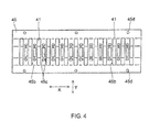
- Fig. 4 is a plan view illustrating the placement of arch cores in the inductive heating unit in this embodiment
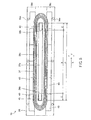
- Fig. 5 is a plan view illustrating the placement of end-side center cores in the inductive heating unit in this embodiment
- Fig. 6A is a graph illustrating changes in temperature on the surface of a heat-generating belt in this embodiment when paper sheets are fed in succession;
- Fig. 6B is a graph illustrating changes in temperature on the surface of the end-side center core in this embodiment when paper sheets are fed in succession.
- Fig. 7 is a sectional plan elevation indicating an exhaust fan and ventilating ducts that cool the inductive heating unit in this embodiment.
- Fig. 8 is a plan view illustrating the placement of temperature sensors.
- Fig. 1 schematically illustrates the structure of an image forming apparatus having a fixing device in the embodiment of the present invention.
- the image forming apparatus 1 has a paper feeding unit 2, a paper conveying unit 3 placed next to the paper feeding unit 2, an image forming unit 4 placed above the paper conveying unit 3, a fixing device 5 placed to the left of the image forming unit 4 in Fig. 1 , and an image reading unit 6 placed above the image forming unit 4 and fixing device 5.
- the paper feeding unit 2 has a plurality of paper feed cassettes 7 that store paper sheets 9, which are examples of recording media.
- the paper feeding unit 2 feeds one paper sheet 9 at a time from one paper feed cassette 7 selected from the plurality of feed cassettes 7 to the paper conveying unit 3 by using the rotation of a feed roller 8.
- the paper 9 fed to the paper conveying unit 3 is conveyed through a paper conveying path 10, which is provided in the paper conveying unit 3, toward the image forming unit 4.
- the image forming unit 4 executes an electrophotographic process to form a toner image on the paper 9.
- the image forming unit 4 has a photosensitive body 11 that is supported so as to be rotatable in a direction indicated by the arrow in Fig. 1 , a charging unit 12 placed around the photosensitive body 11 in the rotational direction of the photosensitive body 11, an exposing unit 13, a developing unit 14, a transcribing unit 15, a cleaning unit 16, and a static eliminating unit 17.
- the charging unit 12 has a charging wire to which a high voltage is applied.
- the charging unit 12 uniformly charges the surface of the photosensitive body 11 by having the charging wire cause a corona discharge to give a prescribed electrical potential to the surface of the photosensitive body 11.
- the electric potential on the surface of the photosensitive body 11 is selectively attenuated, forming an electrostatic latent image on the surface of the photosensitive body 11.
- the developing unit 14 develops the electrostatic latent image on the surface of the photosensitive body 11, forming a toner image on the surface of the photosensitive body 11.
- the toner image is transcribed by the transcribing unit 15 to the paper 9 supplied between the photosensitive body 11 and the transcribing unit 15.
- the paper 9, on which the tonner image has been transcribed is conveyed toward the fixing device 5 disposed downstream of the image forming unit 4 in the paper conveyance direction.
- the paper 9 is heated and pressurized, melting and fixing the toner image on the paper 9.
- the paper 9, on which the toner image has been fixed is ejected onto an ejection tray 21 by an ejection roller pair 20.
- toner remaining on the surface of the photosensitive body 11 is removed by the cleaning unit 16. Charges remaining on the surface of the photosensitive body 11 are removed by the static eliminating unit 17. The photosensitive body 11 is charged again by the charging unit 12 and an image is then formed similarly as described above.
- Fig. 2 is a sectional side elevation that schematically illustrates the fixing device 5.
- the fixing device 5 uses a fixing method in which electromagnetic induction heating is carried out.
- the fixing device 5 has a heat-generating belt 26, which is a heating member, a pressurizing roller 19, which is a pressurizing member, a fixing roller 18 to which the heat-generating belt 26 is integrally attached, an inductive heating unit 30 that supplies a magnetic flux to the heat-generating belt 26, a temperature sensing unit 25, a controller 62 connected to the temperature sensing unit 25 and inductive heating unit 30, and a power supply 61 that supplies a high-frequency current to a coil of the inductive heating unit 30.
- the pressurizing roller 19 and fixing roller 18 are supported so as to be rotatable in the longitudinal direction of a housing (not shown) of the fixing device 5.
- the inductive heating unit 30 and temperature sensing unit 25 are secured to the housing.
- the heat-generating belt 26 is an endless heat-resistant belt.
- the heat-generating belt 26 is formed by sequentially laminating an inductive heat-generating layer 26a, with a thickness of at least 30 ⁇ m and at most 50 ⁇ m, that is formed by, for example, nickel electroforming, an elastic layer 26b, with a thickness of at least 200 ⁇ m and at most 500 ⁇ m, that is formed with, for example, silicone rubber, and a mold releasing layer 26c, formed with, for example, a fluorocarbon resin, that improves the ease with which the mold is released when a non-fused toner image is melted and fixed in a nip part N in that order from the inner circumferential side.
- the fixing roller 18 stretches the inner circumferential surface of the heat-generating belt 26. This enables the heat-generating belt 26 to be rotated together with the fixing roller 18.
- the outer diameter of the fixing roller 18 is, for example, 39.8 mm.
- the fixing roller 18 has, for example, a core metal 18a made of a stainless steel and an elastic layer 18b, formed with silicone rubber, that is placed on the fixing roller 18a so that the thickness of the fixing roller 18 becomes at least 5 mm and at most 10 mm.
- the fixing roller 18b stretches the heat-generating belt 26.
- the pressurizing roller 19 has a core metal 19a, which is cylindrical, an elastic layer 19b formed on the core metal 19a, and mold releasing layer 19c that covers the surface of the elastic layer 19b.
- the outer diameter of the pressurizing roller 19 is, for example, 35 mm.
- the core metal 19a of the pressurizing roller 19 is made of a stainless steel and the elastic layer 19b formed on the pressurizing roller 19a has a thickness of at least 2 mm and at most 5 mm and is made of a silicone rubber.
- a mold releasing layer 19c, formed with, for example, a fluorocarbon resin may be placed on the pressurizing roller 19b.
- the rotation of the pressurizing roller 19 is driven by a motor (not shown) or another driving source.
- the nip part N is formed in an area where the pressurizing roller 19 is brought into pressure contact with the heat-generating belt 26.
- the non-fixed toner image on the paper 9, which has been fed from the image forming unit 4 is heated and pressurized, fixing the toner image on the paper 9.
- the inductive heating unit 30 has a coil 37, a bobbin 38, and a magnetic core 39.
- the inductive heating unit 30 causes the heat-generating belt 26 to generate heat through electromagnetic induction.
- the inductive heating unit 30, which extends in the longitudinal direction (perpendicular to the drawing sheet of Fig. 2 ), is disposed so as to face the heat-generating belt 26 and cover substantially a half of the outer circumference of the heat-generating belt 26.
- the coil 37 is attached to the bobbin 38 by, for example, being wound a plurality of turns in a loop shape in the width direction of the heat-generating belt 26 (perpendicular to the drawing sheet of Fig. 2 ).
- the coil 37 is connected to the power supply 61 to generate an AC magnetic flux from the high-frequency current supplied from the power supply 61.
- the magnetic flux generated by the coil 37 passes through the magnetic core 39, is led in a direction parallel to the drawing sheet of Fig. 2 , and passes through the heat-generating belt 26 so as to pass along the inductive heat-generating layer 26a of the heat-generating belt 26.
- An eddy current is generated in the inductive heat-generating layer 26a due to a change in the intensity of the AC current of the magnetic flux passing through the inductive heat-generating layer 26a.
- Joule heat is generated due to an electric resistance of the inductive heat-generating layer 26a, causing the heat-generating belt 26 to generate heat (the heat-generating belt 26 performs self-heating).
- the temperature sensing unit 25 has a non-contact temperature sensing element 25a, which is a first temperature sensor, and thermistors 25b, which are second temperature sensors. Specifically, the temperature sensing unit 25 is structured so that it senses a temperature on the surface of the heat-generating belt 26.
- the non-contact temperature sensing element 25a is disposed substantially at the center in the width direction of the heat-generating belt 26.
- the non-contact temperature sensing element 25a senses a temperature on the surface of an area, corresponding to a paper-feeding area B, on the heat-generating belt 26 (see Fig. 5 ).
- the thermistors 25b are disposed at portions near one end in the axial direction of the heat-generating belt 26. Each thermistor 25b senses a temperature on the surface of an area, corresponding to one paper non-feeding area C, on the heat-generating belt 26 (see Fig. 5 ).
- the controller 62 has a microcomputer, storage elements including a random-access memory (RAM) and a read-only memory (ROM), and the like.
- the controller 62 controls the high-frequency current supplied from the power supply 61 to the coil 37 according to the temperatures, on the surface of the heat-generating belt 26, that have been sensed by the non-contact temperature sensing element 25a and thermistors 25b. This control may cause the paper 9 fed to the nip part N to be appropriately fixed.
- the controller 62 also controls a spacing between each two paper sheets 9 that are fed to the nip part N in succession according to the temperatures sensed by the non-contact temperature sensing element 25a and thermistors 25b.
- the heat-generating belt 26 When the heat-generating belt 26 is heated to a temperature at which fixing is possible, the paper 9 held in the nip part N is heated and is pressurized by the pressurizing roller 19, so toner transcribed to the paper 9 in a powder state is melted and fixed to the paper 9.
- the heat-generating belt 26 is made of a thin material with superior thermal conductivity, so its thermal capacity is small. Accordingly, the fixing device 5 can be warmed up in a short period of time, enabling image forming to be quickly started.
- Fig. 3 is a sectional side elevation of the inductive heating unit 30.
- the inductive heating unit 30 has the coil 37, the bobbin 38, which is a supporting member, and the magnetic core 39.
- the magnetic core 39 has an arch core 41, which is a first core part, end-side center cores 42, which are second core part, and side cores 43.
- the inductive heating unit 30 further has an arch core holder 45 structured so that the arch core 41 is attached to the arch core holder 45, and a cover 47 that covers the magnetic core 39 and coil 37.
- the bobbin 38 is disposed concentrically with the rotational central axis of the fixing roller 18 with a prescribed spacing between the bobbin 38 and the surface of the heat-generating belt 26.
- the bobbin 38 has an arc part 38i that covers substantially a half of the circumferential surface of the heat-generating belt 26 on its cross section in a direction orthogonal to the rotational central axis.
- the arc part 38i is arc-shaped on the cross section.
- the bobbin 38 also has flanges 38d that extend from both ends of the arc part 38i.
- the arc part 38i and flanges 38d form a main skeletal part of the bobbin 38.
- the bobbin 38 is made of a liquid crystal polymer (LCP) resin, a polyethylene terephthalate (PET) resin, a poly phenylene sulfide (PPS) resin, or another heat-resistant resin.
- LCP liquid crystal polymer
- PET polyethylene terephthalate
- PPS poly phenylene sulfide
- the arc part 38i of the bobbin 38 has an opposite surface 38a that faces the surface of the heat-generating belt 26 with a prescribed spacing therebetween and also has an attachment surface 38b, in an arc shape, that is located on a side opposite to the opposite surface 38a.
- a pair of end-side center cores 42 is attached with an adhesive substantially at the center of the attachment surface 38b, that is, on a line that interconnects the rotational central axes of the fixing roller 18 and pressurizing roller 19 (see Fig. 2 ).
- a standing wall 38c erected from the attachment surface 38b extends around the end-side center cores 42 in the longitudinal direction (perpendicular to the drawing sheet of Fig. 3 ).
- the coil 37 is attached to the attachment surface 38b.
- the spacing between the surface of the heat-generating belt 26 and the opposite surface 38a of the bobbin 38 is, for example, at least 1.5 mm and at most 3 mm to prevent a contact with the opposite surface 38a when the heat-generating belt 26 is rotated.
- the end-side center cores 42 are disposed at a distance of, for example, 4 mm from the surface of the heat-generating belt 26.
- a coil formed by twisting a plurality of enamel wires coated with a fusing layer is used as the coil 37.
- an AIW wire with a heat-resistant temperature of about 200°C is used.
- its fusing layer is melted by, for example, heating the wires in a state in which the wires are wound in a loop shape around the attachment surface 38b, which is in an arch shape on a cross section, in the longitudinal direction (orthogonal to the drawing sheet of Fig. 3 ), after which the coil 37 is cooled.
- the coil 37 solidified in the prescribed shape is placed around the standing wall 38c of the bobbin 38 and is attached to the attachment surface 38b with a silicone adhesive or the like.
- a plurality of side cores 43 are attached to a surface of each flange 38d with an adhesive in the longitudinal direction, the surface being the same side as the arc part 38i.
- the arch core holder 45 is attached on the same side as the outer edges of the flanges 38d.
- the arch core holder 45 has holder flanges 45a attached to the flanges 38d of the bobbin 38 and also has a plurality of core attaching parts 45b, each of which extends in an arch shape from each arch core holder 45a in the longitudinal direction.
- One arch core 41 having substantially the same shape as the core attaching parts 45b is attached to each core attaching part 45b with an adhesive.
- the end-side center cores 42, side cores 43, and arch cores 41 are attached at prescribed positions on the bobbin 38 and arch core holder 45. Accordingly, the arch cores 41 and side cores 43 enclose the outside of the coil 37.
- the end-side center core 42 is disposed closer to the surface of the heat-generating belt 26 than the arch core 41 is.
- the coil 37 is enclosed by the surface of the heat-generating belt 26, the side cores 43, the arch cores 41, and the end-side center cores 42.
- the cover 47 is structured so as to shield the magnetic flux generated from the inductive heating unit 30.
- the cover 47 is structured so that an aluminum plate encloses the periphery of the coil 37 and magnetic core 39 from a side opposite to the bobbin 38.
- the cover 47 is attached by, for example, stacking the arch core holder 45a of the arch core holder 45 and the flange of the cover 47 on the flange 38d of the bobbin 38 in that order and by tightening screws 51 and nuts 52.
- Figs. 4 and 5 illustrate the placement of the magnetic core 39 and bobbin 38.
- Fig. 4 is a plan view illustrating the placement of the arch core 41 with respect to the arch core holder 45 when viewed from the bottom in Fig. 3 (from the bobbin 38).
- Fig. 5 is a plan view illustrating the placement of the coil 37, end-side center core 42, and side core 43 with respect to the bobbin 38 when viewed from the top in Fig. 3 (from the arch core holder 45).
- a plurality of core attaching parts 45b each of which attaches the relevant arch core 41 to a prescribed position, are spaced in the arch core holder 45 at substantially equal intervals in a width direction X (orthogonal to the paper conveyance direction in the drawing sheet).
- a holder opening 45c is formed between each two adjacent core attaching parts 45b.
- a plurality of screw holes 45d are formed in correspondence to the screws 51 (see Fig. 3 ), which attach the arch core holder 45 to the bobbin 38 (see Fig. 3 ), around the core attaching parts 45b.
- the arch core 41 is formed in an arch shape, the cross sectional view of which is rectangular, by using, for example, a ferrite with high magnetic permeability such as a ferrite based on an Mn-Zn alloy.
- the Curie temperature of the arch core 41 is set to a temperature higher than or equal to the temperature of the arch core 41 obtained when the nip part N reaches a temperature at which fixing is possible.
- the temperature of the arch core 41 exceeds its Curie temperature, the magnetic permeability of the arch core 41 is rapidly lowered, resulting in the inability of the arch core 41 to function as a magnetic body.
- the Curie temperature of the arch core 41 is set to a prescribed temperature by, for example, adjusting the ratio of materials (Mn and Zn of an Mn-Zn alloy, for example).
- the arch core 41 has, for example, a width (length in the width direction X) of 10 mm and a thickness of 4.5 mm.
- the arch core 41 is fitted within the length of the coil 37 (see Fig. 5 ) in the width direction X.
- 13 arch cores 41 are equally spaced in a segment 310 mm in length.
- the thermal capacity of the arch core 41 is calculated to be 15 J/K from its specific gravity and specific heat. Since the arch core 41 is formed in, for example, an arch shape, its thermal capacity becomes comparatively large.
- the arch core 41 is placed at a comparatively long distant from the heat-generating belt 26. Therefore, the ease with which the arch core 41 tracks changes in the temperature of the heat-generating belt 26 is inferior when compared with the end-side center core 42.
- the bobbin 38 has the standing wall 38c erected from the attachment surface 38b, the flanges 38d, and a plurality of screw holes 38e formed in correspondence to the screws 51 (see Fig. 3 ).
- a plurality of side cores 43 are attached to each flange 38d.
- the side core 43 is formed in a rectangular parallelepiped shape by using a ferrite with high magnetic permeability such as a ferrite based on an Mn-Zn alloy.
- the Curie temperature of the side core 43 is set to a temperature higher than or equal to the temperature of the side core 43 obtained when the nip part N reaches a temperature at which fixing is possible.
- the temperature of the side core 43 exceeds its Curie temperature, the magnetic permeability of the side core 43 is rapidly lowered, resulting in the inability of the side core 43 to function as a magnetic body.
- the Curie temperature of the side core 43 is set to a prescribed temperature by, for example, adjusting the ratio of materials (such as in an Mn-Zn alloy).
- the side core 43 has, for example, a length (length in the width direction X) of 57 mm, a width (length in the direction Y) of 12 mm, and a thickness of 3.5 mm.
- six side cores 43 are disposed on one flange 38d of the bobbin 38 in the width direction X so that their side surfaces are mutually brought into contact.
- Another six side cores 43 are also disposed on the other flange 38d in the width direction X so that their side surfaces are mutually brought into contact.
- the thermal capacity of one side core 43 is calculated to be, for example, 10 J/K from its specific gravity and specific heat.
- the side core 43 is shaped to the above size and is disposed as described above so that the side surfaces of the side cores 43 are mutually brought into contact, thermal capacity of the side core 43 becomes comparatively large and the ease with which the side core 43 tracks changes in the temperature of the heat-generating belt 26 is inferior when compared with the end-side center core 42.
- the standing wall 38c of the bobbin 38 has first standing walls extending in the width direction X so as to face each other and second standing walls, in an arc shape, extending from the first standing walls, which face each other, and forming outer edges at both ends in the width direction X.
- the outer edge of the standing wall 38c has substantially the same shape as the hollow part 37a formed in the loop of the wound coil 37.
- the hollow part 37a of the coil 37 has, for example, a dimension of 330 mm in the width direction X and a dimension of 10 mm in the direction Y (paper conveyance direction) orthogonal to the width direction X.
- the outer edge of the standing wall 38c has, for example, a dimension of 329 mm in the width direction X and a dimension of 9.4 mm in the direction Y (paper conveyance direction).
- the rectangular space is formed so as to be longer than a paper feeding area A, in the width direction X, for the paper 9 with a maximum size up to which fixing is possible.
- the thickness of the standing wall 38c is set so as to suppress heat generated from the excited coil 37 from being radiated and transferred to the end-side center cores 42.
- the thickness of the standing wall 38c (length from the outer edge to the inner edge) is, for example, 1.5 mm.
- the length of the rectangular space in the direction Y is, for example, 6.4 mm.
- the end-side center core 42 pair is placed in the rectangular space inside the standing wall 38c so that when paper 9 smaller than the paper 9 with the maximum size is inserted into the nip part N, the paper 9 with the small size corresponds to the paper non-feeding areas C formed at both ends of the paper feeding area B for the paper 9 with the small size.
- the end-side center core 42 is formed in a rectangular parallelepiped shape by using, for example, a ferrite with high magnetic permeability such as a ferrite based on an Mn-Zn alloy.
- the Curie temperature of the end-side center core 42 is set to a temperature higher than or equal to the temperature (100°C, for example) of the end-side center core 42 obtained when the nip part N reaches a temperature at which fixing is possible but lower than the Curie temperature of the arch core 41 (see Fig. 4 ).
- the temperature of the end-side center core 42 exceeds its Curie temperature, the magnetic permeability of the end-side center core 42 is rapidly lowered, resulting in the inability of the end-side center core 42 to function as a magnetic body.
- the Curie temperature of the end-side center core 42 is set to, for example, 130°C by, for example, adjusting the ratio of materials (such as in an Mn-Zn alloy).
- the end-side center core 42 has a smaller thermal capacity than the arch core 41.
- the end-side center core 42 has, for example, a length (length in the width direction X) of 18 mm, a width (length in the direction Y) of 5 mm, and a height of 7 mm.
- the thermal capacity of one end-side center core 42 is calculated to be, for example, 2.7 J/K from its specific gravity and specific heat.
- the end-side center core 42 Since the end-side center core 42 has a smaller thermal capacity than the arch core 41 and is placed closer to the heat-generating belt 26 than the arch core 41 is, the ease with which the end-side center core 42 tracks changes in the temperature of the heat-generating belt 26 is superior when compared with the arch core 41. Even if the temperature of the heat-generating belt 26 is raised in the area corresponding to the paper non-feeding area C, since the ease with which the end-side center core 42 tracks changes in the temperature of the heat-generating belt 26 is superior, the heat-generating belt 26 is not thermally damaged at the Curie temperature set for the end-side center core 42.
- the Curie temperature of the end-side center core 42 is set to or below a cooling temperature (about 160°C) set for the coil 37.
- a cooling temperature about 160°C
- the cooling temperature set for the coil 37 is set in consideration of the heat-resistant temperature (about 180°C) of the fusing layer of the coil 37. When the heat-resistant temperature of the fusing layer is exceeded, the coil 37 may be deformed.
- the end-side center core 42 When the Curie temperature of the end-side center core 42 is set to or below the cooling temperature set for the coil 37, however, even if the temperature in the area, corresponding to the paper non-feeding area C, on the heat-generating belt 26 is excessively raised, the end-side center core 42 has an appropriate Curie temperature and loses its magnetism, preventing the end-side center core 42 from being damaged due to heat of the heat-generating belt 26.
- the magnetic flux generated from the coil 37 passes through a magnetic path that includes the inductive heat-generating layer 26a of the heat-generating belt 26, the side cores 43, and the arch cores 41.
- electromagnetic induction causes an eddy current to flow in the inductive heat-generating layer 26a of the heat-generating belt 26 and thereby the inductive heat-generating layer 26a of the heat-generating belt 26 generates heat.
- the magnetic flux generated from the coil 37 passes through a magnetic path that includes the end-side center cores 42, the inductive heat-generating layer 26a of the heat-generating belt 26, the side cores 43, and the arch cores 41.
- electromagnetic induction causes an eddy current to flow in the inductive heat-generating layer 26a of the heat-generating belt 26 and thereby the inductive heat-generating layer 26a of the heat-generating belt 26 generates heat.
- the paper 9 held in the nip part N by the heat-generating belt 26 is heated and is pressurized by the pressurizing roller 19, so toner transcribed to the paper 9 in a powder state is melted and fixed to the paper 9.
- FIG. 6A illustrates changes in the temperature on the surface of the heat-generating belt 26.
- Fig. 6B illustrates changes in the temperature on the end-side center core 42.
- the graphs in Figs. 6A and 6B indicate time in seconds on the horizontal axis and also indicate temperature in degrees Celsius (°C) on the vertical axis.
- first surface temperature T1 is a temperature sensed by the non-contact temperature sensing element 25a (see Fig. 2 )
- second surface temperature T2 is a temperature sensed by the thermistor 25b (see Fig. 2 ).
- TC is the temperature of the end-side center core 42
- TD is the Curie temperature of the end-side center core 42
- TE is the temperature (100°C, for example) of the end-side center core 42 in a standby state.
- the controller 62 (see Fig. 2 ) performs control according to the first surface temperature T1 input from the non-contact temperature sensing element 25a and the second surface temperature T2 input from the thermistor 25b, as described below.
- the first surface temperature T1 and second surface temperature T2 reach a prescribed fixing-ready temperature (180°C, for example) that is, for example, at least 170°C and at most 180 °C.
- a prescribed fixing-ready temperature 180°C, for example
- Small-sized paper 9 which is a first recording medium, undergoes fixing process in the nip part N for a period from s1 to s2.
- the first surface temperature T1 is controlled to the prescribed fixing-ready temperature (180°C, for example). Since the small-sized paper 9 is fixed, temperature is raised in the area, corresponding to the paper non-feeding area C (see Fig.
- the second surface temperature T2 drops and the end-side center core temperature TC also drops below the end-side center core Curie temperature TD at time s4. Since the end-side center core temperature TC drops below the end-side center core Curie temperature TD, a magnetic path is formed in an area, corresponding to each paper non-feeding area C, on the heat-generating belt 26. This magnetic path causes an area, around the paper non-feeding area C, on the heat-generating belt 26 to generate heat, raising the second surface temperature T2.
- the second surface temperature T2 is raised by a prescribed temperature TF (5°C, for example) from the lower fixing-ready temperature limit TB at time s5
- a prescribed temperature TF 5°C, for example
- the prescribed temperature TF is set so that even if there are variations in temperature sensing, fixing process is reliably executed in the fixing-ready temperature range.
- the second fixing process on the large-sized paper 9 a superior image on which a fixing failure due to a low-temperature offset is suppressed is obtained. Furthermore, the second fixing process on the large-sized paper 9 is started at time s5 immediately after the completion of the first fixing process on the large-sized paper 9 at time s4, a time to wait until the second fixing process is performed on the large-sized paper 9 is shortened.
- Fig. 7 illustrates a structure to exhaust heat from the inductive heating unit 30, as a cross sectional view, of the cover 47 that is taken along a line in the width direction X.
- the coil 37, the magnetic core 39, and other components accommodated in the cover 47 are omitted.
- the upper surface of the cover 47 has a first upper-surface opening 47a at one end in the width direction X and also has a second upper-surface opening 47b at another end.
- the first upper-surface opening 47a is formed on an intake side.
- the intake duct 55 is disposed so as to face the first upper-surface opening 47a.
- the second upper-surface opening 47b is formed on an exhaust side.
- the exhaust duct 56 is disposed so as to face the second upper-surface opening 47b.
- the exhaust duct 56 is attached so that an opening formed at one end of the exhaust duct 56 faces the second upper-surface opening 47b and an opening formed at another end faces the exhaust fan 57.
- the exhaust fan 57 is attached so as to face the exhaust duct 56.
- Fig. 8 is a plan view illustrating the placement of the non-contact temperature sensing element 25a and thermistors 25b.
- the non-contact temperature sensing element 25a is placed substantially at the center of the heat-generating belt 26 in the width direction.
- a plurality of thermistors 25b are placed according to, for example, the width of the paper 9 to be fed.
- a thermistor 25b1 is placed outside of A5-sized paper 9 in the width direction
- a thermistor 25b2 is placed outside of A4T-sized paper 9 in the width direction
- a thermistor 25b3 is placed outside of A4Y-sized paper 9 in the width direction.
- the thermistors 25b1 to 25b3 are placed on the downstream side of the heat-generating belt 26 in the width direction X with respect to a direction (indicated by the arrow in Fig. 8 ) in which air is blown by the exhaust fan 57. Although the downstream end in the direction in which air is blown by the exhaust fan 57 is likely to become hot, the thermistors 25b1 to 25b3 placed as described above sense temperatures on the downstream side in the air blow direction and the temperature of the heat-generating belt 26 is controlled accordingly. This can suppress temperatures on the upstream end of the heat-generating belt 26 from being excessively raised.
- a fixing device so far proposed is structured so that whether the temperature of the magnetic core exceeds its Curie temperature is determined by measuring an overcurrent flowing in the coil.
- a member that measures the Curie temperature of the magnetic core is provided. Furthermore, a time to wait from when fixing process has been completed on small-sized paper until fixing process is performed on paper with a fixed size may be prolonged.
- magnetic cores at ends can easily track changes in the temperature of a heating member. It is also possible to shorten a time to wait from when fixing process has been completed on small-sized paper until fixing process is performed on large-sized paper.
- the recording medium with a large width is inserted into the nip part and undergoes fixing process after temperatures at both ends of the heating member are raised above the upper fixing-ready temperature limit with the central part of the heating member at the fixing ready temperature and then drop to or below the upper fixing-ready temperature limit.
- the present invention is not limited to this example.
- the structure in the embodiment in the present invention may be applied to a fixing device in which an endless heat-generating belt is stretched between a heat roller disposed so as to face an inductive heating unit and a fixing roller by which a pressurizing roller is brought into pressure contact.
- the structure in the embodiment may be applied to a fixing device that has an inductive heating unit that heats an endless heat-generating belt, a pressurizing roller by which the outer circumferential surface of the heat generating belt is brought into pressure contact, and a pressing member disposed on the inner circumferential surface of the heat-generating belt so that paper and the heat-generating belt are mutually brought into pressure contact between the pressing roller and the pressing member.
- the structure in the embodiment may be applied to other various types of fixing devices that have an inductive heating member such as a fixing device that has a pressuring roller and a heating roller, which is brought into contact by the pressuring roller, the heating roller internally including an inductive heat-generating layer and being disposed so as to face an inductive heating member.
- the present invention is not limited to this structure.
- the arch core 41 may extend toward the side core 43 and the arch core 41 may include the function of the side core 43.
- the arch core 41 has been attached through the arch core holder 45 to the bobbin 38, the present invention is not limited to this structure.
- the arch core 41 may be attached directly to the bobbin 38.
- a first fixing process is performed on a first recording medium having a smaller width (small size) than a recording medium with a maximum width up to which fixing is possible.
- the first fixing process may be performed on an A5- or A4T-sized paper 9, having a width which is smaller than the maximum width which is represented by the A4Y-sized paper 9.
- a second fixing process on a second recording medium having a larger width than the first recording medium is performed.
- the second fixing process may be performed on an A4T- or A4Y-sized paper, for example.
- Fig. 6A illustrates that the second fixing process (from s3 to s4) is performed after the first fixing process (from s1 to s2) and after a surface temperature T2 in paper non-feeding areas C ( Fig. 5 ) is raised above an upper fixing-ready temperature limit TA.
- the second recording medium (either A4T- or A4Y-sized paper) is inserted into the nip part N formed by the heating member 26 and the pressurizing member 19 after the surface temperature T2 in paper non-feeding areas C drops to or below the upper fixing-ready temperature limit TA (cf. s3).
Landscapes
- Physics & Mathematics (AREA)
- General Physics & Mathematics (AREA)
- Fixing For Electrophotography (AREA)
- General Induction Heating (AREA)
Abstract
Description
- The present invention relates to an electromagnetic induction heating type fixing device and image forming apparatus equipped therewith. Furthermore, the invention relates to a fixing method in which electromagnetic induction heating is carried out.
- In an electromagnetic induction heating type fixing device, an eddy current is generated in an inductive heat-generating layer formed in a heating member by, for example, a magnetic flux generated by an exciting coil. When Joule heat generated by the eddy current causes the heating member to generate heat, the heating member is heated to a prescribed fixing temperature. With this type of fixing device, the thermal capacity of the heating member can be reduced, so a warm-up time can be shortened and a high heat exchanging efficiency can be obtained with a compact structure.
- With this type of fixing device, heat is lost from the surface of the heating member to paper, so a paper feeding area, where paper passes, is likely to be at lower temperature than paper non-feeding areas, where paper does not pass. When paper with a small size is fixed, particularly when paper sheets with a small size are fixed in succession, if an area, corresponding to the paper feeding area, on the heating member is maintained at fixing process temperature, the temperature in the area, corresponding to the paper non-feeding area, on the heating member may be excessively raised. This may cause the temperatures of the heating member and exciting coil to exceed their heatproof temperatures, and they may be damaged.
- In view of the above situation, a previously proposed fixing device has a magnetic core for which its Curie temperature has been set to a temperature that is slightly higher than the fixing process temperature and also has a coil that uses the magnetic core to generate a magnetic flux by which the heating member is inductively heated. The magnetic core in this fixing device has different Curie temperatures in a direction orthogonal to a paper conveyance direction. Specifically, the magnetic core in the fixing device is formed so that the Curie temperature at both ends is lower than the Curie temperature at the central portion in a direction orthogonal to a paper conveyance direction. Even when small paper sheets are fixed in succession, this structure can prevent a large difference in temperature from being caused between the paper feeding area and the paper non-feeding areas. With this type of fixing device, the Curie temperature of end-side magnetic cores at both ends, which are equivalent to that of the paper non-feeding areas at a time when small paper is fed, has been set to a temperature lower than the Curie temperature of a central magnetic core, which is the paper feeding area for small paper. If the temperature in the area, corresponding to the paper non-feeding area, on the heating member is excessively raised during the fixing of small paper and the end-side magnetic cores are thereby heated to or above their Curie temperature due to thermal radiation or thermal conduction from the heating member, the magnetic permeability of the end-side magnetic cores is lowered, reducing the amount of heat generated from the area, corresponding to the paper non-feeding area, on the heating member. Therefore, the temperature in the area, corresponding to the paper non-feeding area, on the heating member can be lowered.
- A magnetic core in another fixing device has a plurality of first magnetic cores, formed in a trapezoidal shape, that are placed in a direction orthogonal to a paper conveyance direction so as to cover a coil that generates a magnetic flux used for inductive heating and also has a plurality of second magnetic cores that are placed in clearances formed by rings of a coil, which is wound in a loop shape, in a direction orthogonal to the paper conveyance direction. The Curie temperature of each end-side magnetic core, corresponding to one paper non-feeding area, of the second magnetic core has been set to a temperature lower than the Curie temperature of the first magnetic core. Each end-side magnetic core, placed separately from the first magnetic core, has a smaller thermal capacity than the first magnetic core. With this structure, even when the temperature in the area, corresponding to the non-feeding area, on the heating member, has been excessively raised, the temperatures of the end-side magnetic core reaches its Curie temperature or higher temperature relatively fast, due to thermal radiation or thermal conduction from the heating member to the end-side magnetic core. This prevents the temperature of the area, corresponding to the non-feeding area, on the heating member from being excessively raised.
- With the commonly known fixing device and methods described above, however, it cannot be thought that the end-side magnetic core adequately tracks changes in the temperature of the heating member.
- If the end-side magnetic core cannot adequately track changes in the temperature of the heating member, a fixing failure may occur because heating in the paper non-feeding areas becomes insufficient. This may happen when small paper sheets are fed in succession and the temperature of the end-side magnetic core corresponding to the paper non-feeding area exceeds their Curie temperature, after which paper with a fixed size larger than the small paper is fed and uniform heating and fixing cannot be performed over the entire surface of the paper with the fixed size.
- In view of the above situation, a proposed fixing device is structured, for example, so that whether the temperature of the magnetic core has exceeded its Curie temperature is determined by measuring an overcurrent flowing in a coil. When an overcurrent flowing in the coil is detected, that is, the temperature of the magnetic core has exceeded its Curie temperature, a time elapsed from a time at which the Curie temperature has been reached is measured. If the elapsed time is longer than or equal to a prescribed time, a nip part is judged to have been adequately heated, after which fixing process is performed on paper sheets with a fixed size. If the elapsed time is shorter than the prescribed time, the nip part is judged not to have been adequately heated, after which fixing process is performed on paper sheets with the fixed size with a prescribed spacing between each two paper sheets.
- The present invention may provide a fixing device and an image forming apparatus equipped with the fixing device, in which magnetic cores at ends can easily track changes in the temperature of a heating member.
- A fixing device in an aspect of the present invention includes a heating member, a pressurizing member that is brought into pressure contact with the heating member, a coil w in a loop shape in the width direction of the heating member, the coil is configured to generate a magnetic flux that inductively heats the heating member, and a magnetic core disposed near the coil. The magnetic core is configured to lead the magnetic flux to an inductive heat-generating layer formed in the heating member. The magnetic core includes a plurality of first core parts and a plurality of second core parts. The plurality of first core parts are placed so as to enclose the coil in a direction orthogonal to a paper conveyance direction in which a recording medium is conveyed. The plurality of second core parts are placed in hollow parts formed by the loops of the coil at both ends in a direction orthogonal to the paper conveyance direction. The plurality of second core parts have a lower Curie temperature than the plurality of first core parts and have a smaller thermal capacity than the plurality of first core parts. When, after a fixing process is performed on a first recording medium having a smaller width than a recording medium with a maximum width up to which fixing is possible and a surface temperature in paper non-feeding areas is raised above an upper fixing-ready temperature limit, a fixing process is performed on a second recording medium having a larger width than the first recording medium, the second recording medium is inserted into a nip part formed by the heating member and the pressurizing member after the surface temperature in paper non-feeding areas drops to or below the upper fixing-ready temperature limit.
- An image forming apparatus in another aspect of the present invention has an image forming unit and the fixing device described above. Furthermore, the present invention relates to a method in which electromagnetic induction heating is carried out. The fixing method comprises a step for providing a fixing device as well as a step for performing a first fixing process on a first recording medium having a smaller width than a recording medium with a maximum width up to which fixing is possible. Moreover another step of the method includes performing a second fixing process on a second recording medium having a larger width than the first recording medium. In particular, the second fixing process is performed after the first fixing process and after a surface temperature in paper non-feeding areas is raised above an upper fixing-ready temperature limit, the paper non-feeding areas being formed at both ends of the heating member in the width direction by the first recording medium. For performing the second fixing process, the second recording medium is inserted into a nip part formed by the heating member and the pressurizing member after the surface temperature in paper non-feeding areas drops to or below the upper fixing-ready temperature limit, so as to adequately track changes in the temperature of the heating member. In another aspect of the inventive method, when the second fixing process is performed on the second recording medium, after the first fixing process is performed on the first recording medium and the second surface temperature is raised above an upper fixing-ready temperature limit, the second recording medium is inserted into the nip part after the second surface temperature drops to or below the upper fixing-ready temperature limit.
- These as well as other aspects, advantages, and alternatives will become apparent to those of ordinary skill in the art by reading the following detailed description with reference where appropriate to the accompanying drawings. Further, it should be understood that the description provided in this summary section and elsewhere in this document is intended to illustrate the claimed subject matter by way of example and not by way of limitation. It should be noted that any of the apparatus features described with reference to the drawings may be applied with the corresponding inventive method and vice versa.
- In the accompanying drawings:
-
Fig. 1 schematically illustrates the structure of an image forming apparatus having a fixing device in an embodiment of the present invention; -
Fig. 2 is a sectional side elevation of the fixing device having an inductive heating unit in this embodiment; -
Fig. 3 is a sectional side elevation of the inductive heating unit in this embodiment; -
Fig. 4 is a plan view illustrating the placement of arch cores in the inductive heating unit in this embodiment; -
Fig. 5 is a plan view illustrating the placement of end-side center cores in the inductive heating unit in this embodiment; -
Fig. 6A is a graph illustrating changes in temperature on the surface of a heat-generating belt in this embodiment when paper sheets are fed in succession; -
Fig. 6B is a graph illustrating changes in temperature on the surface of the end-side center core in this embodiment when paper sheets are fed in succession. -
Fig. 7 is a sectional plan elevation indicating an exhaust fan and ventilating ducts that cool the inductive heating unit in this embodiment; and -
Fig. 8 is a plan view illustrating the placement of temperature sensors. - Example apparatus and units are described herein. Other example embodiments or features may further be utilized, and other changes may be made, without departing from the spirit or scope of the subject matter presented herein. In the following detailed description, reference is made to the accompanying drawings, which form a part thereof.
- The example embodiments described herein are not meant to be limiting. It will be readily understood that the aspects of the present invention, as generally described herein, and illustrated in the drawings, can be arranged, substituted, combined, separated, and designed in a wide variety of different configurations, all of which are explicitly contemplated herein.
- An embodiment of the present invention will be described with reference to the drawings. However, the present invention is not limited to this embodiment. There are no limitations to applications of the embodiment of the present invention and terms used in the embodiment are not limitations.
-
Fig. 1 schematically illustrates the structure of an image forming apparatus having a fixing device in the embodiment of the present invention. Theimage forming apparatus 1 has apaper feeding unit 2, apaper conveying unit 3 placed next to thepaper feeding unit 2, animage forming unit 4 placed above thepaper conveying unit 3, a fixingdevice 5 placed to the left of theimage forming unit 4 inFig. 1 , and animage reading unit 6 placed above theimage forming unit 4 and fixingdevice 5. - The
paper feeding unit 2 has a plurality ofpaper feed cassettes 7 thatstore paper sheets 9, which are examples of recording media. Thepaper feeding unit 2 feeds onepaper sheet 9 at a time from onepaper feed cassette 7 selected from the plurality offeed cassettes 7 to thepaper conveying unit 3 by using the rotation of afeed roller 8. - The
paper 9 fed to thepaper conveying unit 3 is conveyed through apaper conveying path 10, which is provided in thepaper conveying unit 3, toward theimage forming unit 4. Theimage forming unit 4 executes an electrophotographic process to form a toner image on thepaper 9. Theimage forming unit 4 has aphotosensitive body 11 that is supported so as to be rotatable in a direction indicated by the arrow inFig. 1 , a chargingunit 12 placed around thephotosensitive body 11 in the rotational direction of thephotosensitive body 11, an exposingunit 13, a developingunit 14, a transcribingunit 15, acleaning unit 16, and a static eliminatingunit 17. - The charging
unit 12 has a charging wire to which a high voltage is applied. The chargingunit 12 uniformly charges the surface of thephotosensitive body 11 by having the charging wire cause a corona discharge to give a prescribed electrical potential to the surface of thephotosensitive body 11. When light based on image data of, for example, a manuscript read out by theimage reading unit 6 is directed to thephotosensitive body 11 by the exposingunit 13, the electric potential on the surface of thephotosensitive body 11 is selectively attenuated, forming an electrostatic latent image on the surface of thephotosensitive body 11. - Then, the developing
unit 14 develops the electrostatic latent image on the surface of thephotosensitive body 11, forming a toner image on the surface of thephotosensitive body 11. The toner image is transcribed by the transcribingunit 15 to thepaper 9 supplied between thephotosensitive body 11 and the transcribingunit 15. - The
paper 9, on which the tonner image has been transcribed, is conveyed toward the fixingdevice 5 disposed downstream of theimage forming unit 4 in the paper conveyance direction. In thefixing device 5, thepaper 9 is heated and pressurized, melting and fixing the toner image on thepaper 9. Thepaper 9, on which the toner image has been fixed, is ejected onto anejection tray 21 by anejection roller pair 20. - After the toner image has been transcribed onto the
paper 9 by the transcribingunit 15, toner remaining on the surface of thephotosensitive body 11 is removed by thecleaning unit 16. Charges remaining on the surface of thephotosensitive body 11 are removed by the static eliminatingunit 17. Thephotosensitive body 11 is charged again by the chargingunit 12 and an image is then formed similarly as described above. - The fixing
device 5 in the embodiment of the present invention will be described with reference toFig. 2. Fig. 2 is a sectional side elevation that schematically illustrates the fixingdevice 5. - The fixing
device 5 uses a fixing method in which electromagnetic induction heating is carried out. The fixingdevice 5 has a heat-generatingbelt 26, which is a heating member, a pressurizingroller 19, which is a pressurizing member, a fixingroller 18 to which the heat-generatingbelt 26 is integrally attached, aninductive heating unit 30 that supplies a magnetic flux to the heat-generatingbelt 26, a temperature sensing unit 25, acontroller 62 connected to the temperature sensing unit 25 andinductive heating unit 30, and apower supply 61 that supplies a high-frequency current to a coil of theinductive heating unit 30. The pressurizingroller 19 and fixingroller 18 are supported so as to be rotatable in the longitudinal direction of a housing (not shown) of the fixingdevice 5. Theinductive heating unit 30 and temperature sensing unit 25 are secured to the housing. - The heat-generating
belt 26 is an endless heat-resistant belt. The heat-generatingbelt 26 is formed by sequentially laminating an inductive heat-generating layer 26a, with a thickness of at least 30 µm and at most 50 µm, that is formed by, for example, nickel electroforming, an elastic layer 26b, with a thickness of at least 200 µm and at most 500 µm, that is formed with, for example, silicone rubber, and a mold releasing layer 26c, formed with, for example, a fluorocarbon resin, that improves the ease with which the mold is released when a non-fused toner image is melted and fixed in a nip part N in that order from the inner circumferential side. - The fixing
roller 18 stretches the inner circumferential surface of the heat-generatingbelt 26. This enables the heat-generatingbelt 26 to be rotated together with the fixingroller 18. The outer diameter of the fixingroller 18 is, for example, 39.8 mm. The fixingroller 18 has, for example, a core metal 18a made of a stainless steel and an elastic layer 18b, formed with silicone rubber, that is placed on the fixing roller 18a so that the thickness of the fixingroller 18 becomes at least 5 mm and at most 10 mm. The fixing roller 18b stretches the heat-generatingbelt 26. - The pressurizing
roller 19 has a core metal 19a, which is cylindrical, an elastic layer 19b formed on the core metal 19a, and mold releasing layer 19c that covers the surface of the elastic layer 19b. The outer diameter of the pressurizingroller 19 is, for example, 35 mm. The core metal 19a of the pressurizingroller 19 is made of a stainless steel and the elastic layer 19b formed on the pressurizing roller 19a has a thickness of at least 2 mm and at most 5 mm and is made of a silicone rubber. A mold releasing layer 19c, formed with, for example, a fluorocarbon resin may be placed on the pressurizing roller 19b. The rotation of the pressurizingroller 19 is driven by a motor (not shown) or another driving source. When the pressurizingroller 19 is rotated, the heat-generatingbelt 26 is also rotated accordingly. The nip part N is formed in an area where the pressurizingroller 19 is brought into pressure contact with the heat-generatingbelt 26. In the nip part N, the non-fixed toner image on thepaper 9, which has been fed from theimage forming unit 4, is heated and pressurized, fixing the toner image on thepaper 9. - The
inductive heating unit 30 has acoil 37, abobbin 38, and amagnetic core 39. Theinductive heating unit 30 causes the heat-generatingbelt 26 to generate heat through electromagnetic induction. Theinductive heating unit 30, which extends in the longitudinal direction (perpendicular to the drawing sheet ofFig. 2 ), is disposed so as to face the heat-generatingbelt 26 and cover substantially a half of the outer circumference of the heat-generatingbelt 26. - The
coil 37 is attached to thebobbin 38 by, for example, being wound a plurality of turns in a loop shape in the width direction of the heat-generating belt 26 (perpendicular to the drawing sheet ofFig. 2 ). Thecoil 37 is connected to thepower supply 61 to generate an AC magnetic flux from the high-frequency current supplied from thepower supply 61. The magnetic flux generated by thecoil 37 passes through themagnetic core 39, is led in a direction parallel to the drawing sheet ofFig. 2 , and passes through the heat-generatingbelt 26 so as to pass along the inductive heat-generating layer 26a of the heat-generatingbelt 26. An eddy current is generated in the inductive heat-generating layer 26a due to a change in the intensity of the AC current of the magnetic flux passing through the inductive heat-generating layer 26a. When the eddy current flows in the inductive heat-generating layer 26a, Joule heat is generated due to an electric resistance of the inductive heat-generating layer 26a, causing the heat-generatingbelt 26 to generate heat (the heat-generatingbelt 26 performs self-heating). - The temperature sensing unit 25 has a non-contact
temperature sensing element 25a, which is a first temperature sensor, and thermistors 25b, which are second temperature sensors. Specifically, the temperature sensing unit 25 is structured so that it senses a temperature on the surface of the heat-generatingbelt 26. The non-contacttemperature sensing element 25a is disposed substantially at the center in the width direction of the heat-generatingbelt 26. The non-contacttemperature sensing element 25a senses a temperature on the surface of an area, corresponding to a paper-feeding area B, on the heat-generating belt 26 (seeFig. 5 ). The thermistors 25b are disposed at portions near one end in the axial direction of the heat-generatingbelt 26. Each thermistor 25b senses a temperature on the surface of an area, corresponding to one paper non-feeding area C, on the heat-generating belt 26 (seeFig. 5 ). - The
controller 62 has a microcomputer, storage elements including a random-access memory (RAM) and a read-only memory (ROM), and the like. Thecontroller 62 controls the high-frequency current supplied from thepower supply 61 to thecoil 37 according to the temperatures, on the surface of the heat-generatingbelt 26, that have been sensed by the non-contacttemperature sensing element 25a and thermistors 25b. This control may cause thepaper 9 fed to the nip part N to be appropriately fixed. Thecontroller 62 also controls a spacing between each twopaper sheets 9 that are fed to the nip part N in succession according to the temperatures sensed by the non-contacttemperature sensing element 25a and thermistors 25b. - When the heat-generating
belt 26 is heated to a temperature at which fixing is possible, thepaper 9 held in the nip part N is heated and is pressurized by the pressurizingroller 19, so toner transcribed to thepaper 9 in a powder state is melted and fixed to thepaper 9. In this embodiment, the heat-generatingbelt 26 is made of a thin material with superior thermal conductivity, so its thermal capacity is small. Accordingly, the fixingdevice 5 can be warmed up in a short period of time, enabling image forming to be quickly started. - The structure of the
inductive heating unit 30 will be described in further detail with reference toFig. 3. Fig. 3 is a sectional side elevation of theinductive heating unit 30. - As described above, the
inductive heating unit 30 has thecoil 37, thebobbin 38, which is a supporting member, and themagnetic core 39. Themagnetic core 39 has anarch core 41, which is a first core part, end-side center cores 42, which are second core part, andside cores 43. Theinductive heating unit 30 further has anarch core holder 45 structured so that thearch core 41 is attached to thearch core holder 45, and acover 47 that covers themagnetic core 39 andcoil 37. - The
bobbin 38 is disposed concentrically with the rotational central axis of the fixingroller 18 with a prescribed spacing between thebobbin 38 and the surface of the heat-generatingbelt 26. Thebobbin 38 has an arc part 38i that covers substantially a half of the circumferential surface of the heat-generatingbelt 26 on its cross section in a direction orthogonal to the rotational central axis. The arc part 38i is arc-shaped on the cross section. Thebobbin 38 also hasflanges 38d that extend from both ends of the arc part 38i. The arc part 38i andflanges 38d form a main skeletal part of thebobbin 38. They are at least 1mm and at most 2 mm, preferably, for example, 1.5 mm in thickness so that the strength of the skeletal part can be maintained. To withstand heat released from the heat-generatingbelt 26, thebobbin 38 is made of a liquid crystal polymer (LCP) resin, a polyethylene terephthalate (PET) resin, a poly phenylene sulfide (PPS) resin, or another heat-resistant resin. - The arc part 38i of the
bobbin 38 has an opposite surface 38a that faces the surface of the heat-generatingbelt 26 with a prescribed spacing therebetween and also has anattachment surface 38b, in an arc shape, that is located on a side opposite to the opposite surface 38a. A pair of end-side center cores 42 is attached with an adhesive substantially at the center of theattachment surface 38b, that is, on a line that interconnects the rotational central axes of the fixingroller 18 and pressurizing roller 19 (seeFig. 2 ). A standingwall 38c erected from theattachment surface 38b extends around the end-side center cores 42 in the longitudinal direction (perpendicular to the drawing sheet ofFig. 3 ). Thecoil 37 is attached to theattachment surface 38b. The spacing between the surface of the heat-generatingbelt 26 and the opposite surface 38a of thebobbin 38 is, for example, at least 1.5 mm and at most 3 mm to prevent a contact with the opposite surface 38a when the heat-generatingbelt 26 is rotated. The end-side center cores 42 are disposed at a distance of, for example, 4 mm from the surface of the heat-generatingbelt 26. - A coil formed by twisting a plurality of enamel wires coated with a fusing layer is used as the
coil 37. For example, an AIW wire with a heat-resistant temperature of about 200°C is used. To form thecoil 37 in a prescribed shape (loop shape), its fusing layer is melted by, for example, heating the wires in a state in which the wires are wound in a loop shape around theattachment surface 38b, which is in an arch shape on a cross section, in the longitudinal direction (orthogonal to the drawing sheet ofFig. 3 ), after which thecoil 37 is cooled. Thecoil 37 solidified in the prescribed shape is placed around the standingwall 38c of thebobbin 38 and is attached to theattachment surface 38b with a silicone adhesive or the like. - A plurality of
side cores 43 are attached to a surface of eachflange 38d with an adhesive in the longitudinal direction, the surface being the same side as the arc part 38i. Thearch core holder 45 is attached on the same side as the outer edges of theflanges 38d. - The
arch core holder 45 hasholder flanges 45a attached to theflanges 38d of thebobbin 38 and also has a plurality ofcore attaching parts 45b, each of which extends in an arch shape from eacharch core holder 45a in the longitudinal direction. Onearch core 41 having substantially the same shape as thecore attaching parts 45b is attached to eachcore attaching part 45b with an adhesive. - As described above, the end-
side center cores 42,side cores 43, andarch cores 41 are attached at prescribed positions on thebobbin 38 andarch core holder 45. Accordingly, thearch cores 41 andside cores 43 enclose the outside of thecoil 37. The end-side center core 42 is disposed closer to the surface of the heat-generatingbelt 26 than thearch core 41 is. Thecoil 37 is enclosed by the surface of the heat-generatingbelt 26, theside cores 43, thearch cores 41, and the end-side center cores 42. When a high-frequency current is supplied to thecoil 37, the magnetic flux generated from thecoil 37 is led to theside core 43,arch cores 41, and end-side center core 42, after which the magnetic flux flows along the heat-generatingbelt 26. At that time, since an eddy current flows in the inductive heat-generating layer 26a of the heat-generatingbelt 26, Joule heat is generated in the inductive heat-generating layer 26a due to the electric resistance of the inductive heat-generating layer 26a, causing the heat-generatingbelt 26 to generate heat. - The
cover 47 is structured so as to shield the magnetic flux generated from theinductive heating unit 30. For example, thecover 47 is structured so that an aluminum plate encloses the periphery of thecoil 37 andmagnetic core 39 from a side opposite to thebobbin 38. Thecover 47 is attached by, for example, stacking thearch core holder 45a of thearch core holder 45 and the flange of thecover 47 on theflange 38d of thebobbin 38 in that order and by tighteningscrews 51 and nuts 52. -
Figs. 4 and5 illustrate the placement of themagnetic core 39 andbobbin 38.Fig. 4 is a plan view illustrating the placement of thearch core 41 with respect to thearch core holder 45 when viewed from the bottom inFig. 3 (from the bobbin 38).Fig. 5 is a plan view illustrating the placement of thecoil 37, end-side center core 42, andside core 43 with respect to thebobbin 38 when viewed from the top inFig. 3 (from the arch core holder 45). - As illustrated in
Fig. 4 , a plurality ofcore attaching parts 45b, each of which attaches the relevantarch core 41 to a prescribed position, are spaced in thearch core holder 45 at substantially equal intervals in a width direction X (orthogonal to the paper conveyance direction in the drawing sheet). Aholder opening 45c is formed between each two adjacentcore attaching parts 45b. A plurality ofscrew holes 45d are formed in correspondence to the screws 51 (seeFig. 3 ), which attach thearch core holder 45 to the bobbin 38 (seeFig. 3 ), around thecore attaching parts 45b. - The
arch core 41 is formed in an arch shape, the cross sectional view of which is rectangular, by using, for example, a ferrite with high magnetic permeability such as a ferrite based on an Mn-Zn alloy. The Curie temperature of thearch core 41 is set to a temperature higher than or equal to the temperature of thearch core 41 obtained when the nip part N reaches a temperature at which fixing is possible. When the temperature of thearch core 41 exceeds its Curie temperature, the magnetic permeability of thearch core 41 is rapidly lowered, resulting in the inability of thearch core 41 to function as a magnetic body. The Curie temperature of thearch core 41 is set to a prescribed temperature by, for example, adjusting the ratio of materials (Mn and Zn of an Mn-Zn alloy, for example). Thearch core 41 has, for example, a width (length in the width direction X) of 10 mm and a thickness of 4.5 mm. Thearch core 41 is fitted within the length of the coil 37 (seeFig. 5 ) in the width direction X. For example, 13arch cores 41 are equally spaced in a segment 310 mm in length. The thermal capacity of thearch core 41 is calculated to be 15 J/K from its specific gravity and specific heat. Since thearch core 41 is formed in, for example, an arch shape, its thermal capacity becomes comparatively large. Thearch core 41 is placed at a comparatively long distant from the heat-generatingbelt 26. Therefore, the ease with which thearch core 41 tracks changes in the temperature of the heat-generatingbelt 26 is inferior when compared with the end-side center core 42. - As illustrated in
Fig. 5 , thebobbin 38 has the standingwall 38c erected from theattachment surface 38b, theflanges 38d, and a plurality ofscrew holes 38e formed in correspondence to the screws 51 (seeFig. 3 ). A plurality ofside cores 43 are attached to eachflange 38d. - The
side core 43 is formed in a rectangular parallelepiped shape by using a ferrite with high magnetic permeability such as a ferrite based on an Mn-Zn alloy. The Curie temperature of theside core 43 is set to a temperature higher than or equal to the temperature of theside core 43 obtained when the nip part N reaches a temperature at which fixing is possible. When the temperature of theside core 43 exceeds its Curie temperature, the magnetic permeability of theside core 43 is rapidly lowered, resulting in the inability of theside core 43 to function as a magnetic body. The Curie temperature of theside core 43 is set to a prescribed temperature by, for example, adjusting the ratio of materials (such as in an Mn-Zn alloy). Theside core 43 has, for example, a length (length in the width direction X) of 57 mm, a width (length in the direction Y) of 12 mm, and a thickness of 3.5 mm. For example, sixside cores 43 are disposed on oneflange 38d of thebobbin 38 in the width direction X so that their side surfaces are mutually brought into contact. Another sixside cores 43 are also disposed on theother flange 38d in the width direction X so that their side surfaces are mutually brought into contact. The thermal capacity of oneside core 43 is calculated to be, for example, 10 J/K from its specific gravity and specific heat. Since theside core 43 is shaped to the above size and is disposed as described above so that the side surfaces of theside cores 43 are mutually brought into contact, thermal capacity of theside core 43 becomes comparatively large and the ease with which theside core 43 tracks changes in the temperature of the heat-generatingbelt 26 is inferior when compared with the end-side center core 42. - The standing
wall 38c of thebobbin 38 has first standing walls extending in the width direction X so as to face each other and second standing walls, in an arc shape, extending from the first standing walls, which face each other, and forming outer edges at both ends in the width direction X. - The outer edge of the standing
wall 38c has substantially the same shape as thehollow part 37a formed in the loop of thewound coil 37. When thehollow part 37a of thecoil 37 is inserted into the interior of the standingwall 38c, thecoil 37 can be attached to thebobbin 38. Thehollow part 37a of thecoil 37 has, for example, a dimension of 330 mm in the width direction X and a dimension of 10 mm in the direction Y (paper conveyance direction) orthogonal to the width direction X. The outer edge of the standingwall 38c has, for example, a dimension of 329 mm in the width direction X and a dimension of 9.4 mm in the direction Y (paper conveyance direction). - A rectangular space, in which a pair of
center cores 42 is placed, is formed inside the standingwall 38c. The rectangular space is formed so as to be longer than a paper feeding area A, in the width direction X, for thepaper 9 with a maximum size up to which fixing is possible. The thickness of the standingwall 38c is set so as to suppress heat generated from theexcited coil 37 from being radiated and transferred to the end-side center cores 42. The thickness of the standingwall 38c (length from the outer edge to the inner edge) is, for example, 1.5 mm. The length of the rectangular space in the direction Y is, for example, 6.4 mm. - The end-
side center core 42 pair is placed in the rectangular space inside the standingwall 38c so that whenpaper 9 smaller than thepaper 9 with the maximum size is inserted into the nip part N, thepaper 9 with the small size corresponds to the paper non-feeding areas C formed at both ends of the paper feeding area B for thepaper 9 with the small size. - The end-
side center core 42 is formed in a rectangular parallelepiped shape by using, for example, a ferrite with high magnetic permeability such as a ferrite based on an Mn-Zn alloy. The Curie temperature of the end-side center core 42 is set to a temperature higher than or equal to the temperature (100°C, for example) of the end-side center core 42 obtained when the nip part N reaches a temperature at which fixing is possible but lower than the Curie temperature of the arch core 41 (seeFig. 4 ). When the temperature of the end-side center core 42 exceeds its Curie temperature, the magnetic permeability of the end-side center core 42 is rapidly lowered, resulting in the inability of the end-side center core 42 to function as a magnetic body. The Curie temperature of the end-side center core 42 is set to, for example, 130°C by, for example, adjusting the ratio of materials (such as in an Mn-Zn alloy). The end-side center core 42 has a smaller thermal capacity than thearch core 41. The end-side center core 42 has, for example, a length (length in the width direction X) of 18 mm, a width (length in the direction Y) of 5 mm, and a height of 7 mm. The thermal capacity of one end-side center core 42 is calculated to be, for example, 2.7 J/K from its specific gravity and specific heat. Since the end-side center core 42 has a smaller thermal capacity than thearch core 41 and is placed closer to the heat-generatingbelt 26 than thearch core 41 is, the ease with which the end-side center core 42 tracks changes in the temperature of the heat-generatingbelt 26 is superior when compared with thearch core 41. Even if the temperature of the heat-generatingbelt 26 is raised in the area corresponding to the paper non-feeding area C, since the ease with which the end-side center core 42 tracks changes in the temperature of the heat-generatingbelt 26 is superior, the heat-generatingbelt 26 is not thermally damaged at the Curie temperature set for the end-side center core 42. - The Curie temperature of the end-
side center core 42 is set to or below a cooling temperature (about 160°C) set for thecoil 37. Although the heat-resistant temperature of thecoil 37 is 200°C, the cooling temperature set for thecoil 37 is set in consideration of the heat-resistant temperature (about 180°C) of the fusing layer of thecoil 37. When the heat-resistant temperature of the fusing layer is exceeded, thecoil 37 may be deformed. When the Curie temperature of the end-side center core 42 is set to or below the cooling temperature set for thecoil 37, however, even if the temperature in the area, corresponding to the paper non-feeding area C, on the heat-generatingbelt 26 is excessively raised, the end-side center core 42 has an appropriate Curie temperature and loses its magnetism, preventing the end-side center core 42 from being damaged due to heat of the heat-generatingbelt 26. - In the paper feeding area B in the
fixing device 5 in this embodiment, the magnetic flux generated from thecoil 37 passes through a magnetic path that includes the inductive heat-generating layer 26a of the heat-generatingbelt 26, theside cores 43, and thearch cores 41. Thus, electromagnetic induction causes an eddy current to flow in the inductive heat-generating layer 26a of the heat-generatingbelt 26 and thereby the inductive heat-generating layer 26a of the heat-generatingbelt 26 generates heat. In the paper non-feeding area C, the magnetic flux generated from thecoil 37 passes through a magnetic path that includes the end-side center cores 42, the inductive heat-generating layer 26a of the heat-generatingbelt 26, theside cores 43, and thearch cores 41. Thus, electromagnetic induction causes an eddy current to flow in the inductive heat-generating layer 26a of the heat-generatingbelt 26 and thereby the inductive heat-generating layer 26a of the heat-generatingbelt 26 generates heat. Thepaper 9 held in the nip part N by the heat-generatingbelt 26 is heated and is pressurized by the pressurizingroller 19, so toner transcribed to thepaper 9 in a powder state is melted and fixed to thepaper 9. - A spacing between each two
paper sheets 9 is controlled on the basis of the temperature on the surface of the heat-generatingbelt 26 as illustrated inFigs. 6A and 6B. Fig. 6A illustrates changes in the temperature on the surface of the heat-generatingbelt 26.Fig. 6B illustrates changes in the temperature on the end-side center core 42. The graphs inFigs. 6A and 6B indicate time in seconds on the horizontal axis and also indicate temperature in degrees Celsius (°C) on the vertical axis. InFig. 6A , first surface temperature T1 is a temperature sensed by the non-contacttemperature sensing element 25a (seeFig. 2 ) and second surface temperature T2 is a temperature sensed by the thermistor 25b (seeFig. 2 ). When the surface temperature of the heat-generatingbelt 26 is between an upper fixing-ready temperature limit TA (200°C, for example), up to which fixing is possible, and a lower fixing-ready temperature limit TB (165°C, for example), down to which fixing is possible, a superior image on which an uneven gloss and other problems are suppressed can be obtained. InFig. 6B , TC is the temperature of the end-side center core 42, TD is the Curie temperature of the end-side center core 42, and TE is the temperature (100°C, for example) of the end-side center core 42 in a standby state. - The controller 62 (see
Fig. 2 ) performs control according to the first surface temperature T1 input from the non-contacttemperature sensing element 25a and the second surface temperature T2 input from the thermistor 25b, as described below. - At time s1, the first surface temperature T1 and second surface temperature T2 reach a prescribed fixing-ready temperature (180°C, for example) that is, for example, at least 170°C and at most 180 °C. Small-
sized paper 9, which is a first recording medium, undergoes fixing process in the nip part N for a period from s1 to s2. During paper feeding in this period from s1 to s2 and later periods as well, the first surface temperature T1 is controlled to the prescribed fixing-ready temperature (180°C, for example). Since the small-sized paper 9 is fixed, temperature is raised in the area, corresponding to the paper non-feeding area C (seeFig. 5 ), on the heat-generatingbelt 26 in the period from s1 to s2; for example, temperature is raised to almost 230°C, which is the heat-resistant temperature of the heat-generatingbelt 26. The end-side center core temperature TC is raised from the end-side center core temperature TE in a standby state to the end-side center core Curie temperature TD and is further raised. Upon completion of the fixing process at time s2, the second surface temperature T2 rapidly drops, but the end-side center core temperature TC gradually drops. - When the second surface temperature T2 drops to the upper fixing-ready temperature limit TA at time s3, a superior image is obtained, then large-
sized paper 9, which is a second recording medium, is inserted into the nip part N and fixing process is performed on the large-sized paper 9 regardless of the value of the end-side center core temperature TC. In a period from time s3 to s4 during which fixing process is performed on the large-sized paper 9, the first surface temperature T1 is controlled to the prescribed fixing-ready temperature and the second surface temperature T2 is between the upper fixing-ready temperature limit TA and the lower fixing-ready temperature limit TB. In fixing process on the large-sized paper 9, therefore, a superior image on which an uneven gloss and other problems are suppressed can be obtained. Since the fixing process on the large-sized paper 9 is started immediately after the completion of the fixing process on the small-sized paper 9, a time to wait until the fixing process is performed on the large-sized paper 9 is shortened. - As the fixing process on the large-
sized paper 9 proceeds, the second surface temperature T2 drops and the end-side center core temperature TC also drops below the end-side center core Curie temperature TD at time s4. Since the end-side center core temperature TC drops below the end-side center core Curie temperature TD, a magnetic path is formed in an area, corresponding to each paper non-feeding area C, on the heat-generatingbelt 26. This magnetic path causes an area, around the paper non-feeding area C, on the heat-generatingbelt 26 to generate heat, raising the second surface temperature T2. When the second surface temperature T2 is raised by a prescribed temperature TF (5°C, for example) from the lower fixing-ready temperature limit TB at time s5, the subsequent large-sized paper 9, which is the second recording medium, is inserted into the nip area N and fixing process is performed on the large-sized paper 9. The prescribed temperature TF is set so that even if there are variations in temperature sensing, fixing process is reliably executed in the fixing-ready temperature range. - In the second fixing process on the large-
sized paper 9, a superior image on which a fixing failure due to a low-temperature offset is suppressed is obtained. Furthermore, the second fixing process on the large-sized paper 9 is started at time s5 immediately after the completion of the first fixing process on the large-sized paper 9 at time s4, a time to wait until the second fixing process is performed on the large-sized paper 9 is shortened. -
Fig. 7 illustrates a structure to exhaust heat from theinductive heating unit 30, as a cross sectional view, of thecover 47 that is taken along a line in the width direction X. InFig. 7 , thecoil 37, themagnetic core 39, and other components accommodated in thecover 47 are omitted. - When the coil 37 (see
Fig. 3 ) is energized so as to generate a magnetic flux and thecoil 37 generates heat by itself, temperature in thecover 47 may be raised. Since, in this embodiment, anintake duct 55, anexhaust duct 56, which is a ventilation path, and anexhaust fan 57 are provided, it is possible to suppress the temperature of thecoil 37 from being raised. - The upper surface of the
cover 47 has a first upper-surface opening 47a at one end in the width direction X and also has a second upper-surface opening 47b at another end. The first upper-surface opening 47a is formed on an intake side. Theintake duct 55 is disposed so as to face the first upper-surface opening 47a. The second upper-surface opening 47b is formed on an exhaust side. Theexhaust duct 56 is disposed so as to face the second upper-surface opening 47b. Theexhaust duct 56 is attached so that an opening formed at one end of theexhaust duct 56 faces the second upper-surface opening 47b and an opening formed at another end faces theexhaust fan 57. Theexhaust fan 57 is attached so as to face theexhaust duct 56. - When the rotation of the
exhaust fan 57 is driven, air is externally inhaled from theintake duct 55 through the first upper-surface opening 47a into thecover 47. An air jet formed by theexhaust fan 57 causes air, which has been made hot by heat generated from the coil 37 (seeFig. 3 ), to be exhausted from theexhaust duct 56 through the second upper-surface opening 47b to the outside. -
Fig. 8 is a plan view illustrating the placement of the non-contacttemperature sensing element 25a and thermistors 25b. The non-contacttemperature sensing element 25a is placed substantially at the center of the heat-generatingbelt 26 in the width direction. As illustrated inFig. 8 , a plurality of thermistors 25b are placed according to, for example, the width of thepaper 9 to be fed. For example, as illustrated inFig. 8 , a thermistor 25b1 is placed outside of A5-sized paper 9 in the width direction, a thermistor 25b2 is placed outside of A4T-sized paper 9 in the width direction, and a thermistor 25b3 is placed outside of A4Y-sized paper 9 in the width direction. The thermistors 25b1 to 25b3 are placed on the downstream side of the heat-generatingbelt 26 in the width direction X with respect to a direction (indicated by the arrow inFig. 8 ) in which air is blown by theexhaust fan 57. Although the downstream end in the direction in which air is blown by theexhaust fan 57 is likely to become hot, the thermistors 25b1 to 25b3 placed as described above sense temperatures on the downstream side in the air blow direction and the temperature of the heat-generatingbelt 26 is controlled accordingly. This can suppress temperatures on the upstream end of the heat-generatingbelt 26 from being excessively raised. - As described above, a fixing device so far proposed is structured so that whether the temperature of the magnetic core exceeds its Curie temperature is determined by measuring an overcurrent flowing in the coil. In this fixing device, however, a member that measures the Curie temperature of the magnetic core is provided. Furthermore, a time to wait from when fixing process has been completed on small-sized paper until fixing process is performed on paper with a fixed size may be prolonged.
- In the fixing device in this embodiment and the image forming apparatus equipped with the fixing device, magnetic cores at ends can easily track changes in the temperature of a heating member. It is also possible to shorten a time to wait from when fixing process has been completed on small-sized paper until fixing process is performed on large-sized paper.
- In this embodiment in the present invention, when fixing process is performed on a recording medium with a large width after the completion of fixing process on a recording medium with a small width under control as described with reference to
Figs. 6A and 6B , the recording medium with a large width is inserted into the nip part and undergoes fixing process after temperatures at both ends of the heating member are raised above the upper fixing-ready temperature limit with the central part of the heating member at the fixing ready temperature and then drop to or below the upper fixing-ready temperature limit. Accordingly, after the completion of fixing process on the recording medium with a small width, fixing process is performed on the recording medium with a large width regardless of whether the temperatures of the second core parts have reached their Curie temperature, so a time to wait until the fixing process is performed on the recording medium with a large width is shortened. And a superior image on which an uneven gloss and other problems are suppressed can be obtained. - Although, in the above embodiment, the fixing
device 5 in which the heat-generatingbelt 26 is stretched by the fixingroller 18 has been taken as an example, the present invention is not limited to this example. For example, the structure in the embodiment in the present invention may be applied to a fixing device in which an endless heat-generating belt is stretched between a heat roller disposed so as to face an inductive heating unit and a fixing roller by which a pressurizing roller is brought into pressure contact. Alternatively, the structure in the embodiment may be applied to a fixing device that has an inductive heating unit that heats an endless heat-generating belt, a pressurizing roller by which the outer circumferential surface of the heat generating belt is brought into pressure contact, and a pressing member disposed on the inner circumferential surface of the heat-generating belt so that paper and the heat-generating belt are mutually brought into pressure contact between the pressing roller and the pressing member. In addition, the structure in the embodiment may be applied to other various types of fixing devices that have an inductive heating member such as a fixing device that has a pressuring roller and a heating roller, which is brought into contact by the pressuring roller, the heating roller internally including an inductive heat-generating layer and being disposed so as to face an inductive heating member. - Although, in the above embodiment, the
arch core 41 andside core 43 have been separately disposed, the present invention is not limited to this structure. Thearch core 41 may extend toward theside core 43 and thearch core 41 may include the function of theside core 43. - Although, in the above embodiment, the
arch core 41 has been attached through thearch core holder 45 to thebobbin 38, the present invention is not limited to this structure. Thearch core 41 may be attached directly to thebobbin 38. - In the following, the inventive method is described in more detail with reference to the accompanied drawings. As illustrated between s1 and s2 in
Fig. 6A , in a first step a first fixing process is performed on a first recording medium having a smaller width (small size) than a recording medium with a maximum width up to which fixing is possible. With particular reference to the specific example ofFig. 8 , the first fixing process may be performed on an A5- or A4T-sized paper 9, having a width which is smaller than the maximum width which is represented by the A4Y-sized paper 9. Subsequently, a second fixing process on a second recording medium having a larger width than the first recording medium is performed. That is, if the first recording medium was an A5-sized paper 9, the second fixing process may be performed on an A4T- or A4Y-sized paper, for example.Fig. 6A illustrates that the second fixing process (from s3 to s4) is performed after the first fixing process (from s1 to s2) and after a surface temperature T2 in paper non-feeding areas C (Fig. 5 ) is raised above an upper fixing-ready temperature limit TA. For performing the second fixing process, the second recording medium (either A4T- or A4Y-sized paper) is inserted into the nip part N formed by theheating member 26 and the pressurizingmember 19 after the surface temperature T2 in paper non-feeding areas C drops to or below the upper fixing-ready temperature limit TA (cf. s3). - The present invention is not to be limited in terms of the particular embodiments described in this application, which are intended as illustrations of various aspects. Many modifications and variations can be made without departing from its spirit and scope, as will be apparent to those skilled in the art. Functionally equivalent apparatuses and particularly aspects of the inventive method within the scope of the invention, in addition to those enumerated herein, will be apparent to those skilled in the art from the foregoing descriptions. Such modifications and variations are intended to fall within the scope of the appended claims.
Claims (14)
- A fixing device (5) comprising:- a heating member (26);- a pressurizing member (19) that is brought into pressure contact with the heating member (26);- a coil (37) wound in a loop shape in a width direction of the heating member (26), the coil (37) being configured to generate a magnetic flux that inductively heats the heating member (26); and- a magnetic core (39) disposed near the coil (37), the magnetic core (39) being configured to lead the magnetic flux to an inductive heat-generating layer (26a) formed in the heating member (26),wherein the magnetic core (39) comprises a plurality of first core parts (41) that are placed so as to enclose the coil (37) in a direction orthogonal to a paper conveyance direction in which a recording medium is conveyed, and further a plurality of second core parts (42) that are placed in hollow parts (37a) formed by loops of the coil (37) at both ends in the direction orthogonal to the paper conveyance direction,
wherein the plurality of second core parts (42) have a lower Curie temperature than the plurality of first core parts (41) and have a smaller thermal capacity than the plurality of first core parts (41). - The fixing device (5) according to claim 1, wherein the fixing device further comprises a controller adapted to control the fixing device in such a way that when, after a fixing process is performed on a first recording medium having a smaller width than a recording medium with a maximum width up to which fixing is possible and a surface temperature (T2) in paper non-feeding areas (C) is raised above an upper fixing-ready temperature limit, fixing process is performed on a second recording medium having a larger width than the first recording medium, the second recording medium is inserted into a nip part (N) formed by the heating member (26) and the pressurizing member (19) after the surface temperature (T2) in paper non-feeding areas (C) drops to or below the upper fixing-ready temperature limit.
- The fixing device (5) according to Claim 2, further comprising:- a first temperature sensor (25a) for sensing a first surface temperature (T1) at a center of the heating member (26) in the width direction;- a second temperature sensor (25b) for sensing a second surface temperature (T2), the second surface temperature (T2) being the surface temperature in paper non-feeding areas (C) that are formed at both ends of the heating member (26) in the width direction by the first recording medium.
- The fixing device (5) according to Claim 3, wherein the controller (62) is adapted to control a high-frequency current to be supplied to the coil (37) so that the first surface temperature (T1) reaches a prescribed fixing ready temperature, and also to control timings at which a plurality of recording media are fed in succession to the nip part (N), according to the first surface temperature (T1) sensed by the first temperature sensor (25a) and the second surface temperature (T2) sensed by the second temperature sensor (25b).
- The fixing device (5) according to Claim 4, wherein the controller (62) is adapted to insert a subsequent second recording medium into the nip part (N) after the second surface temperature (T2) is raised by a prescribed temperature from a lower fixing-ready temperature limit, when a fixing
process is performed on a plurality of second recording media in succession after a fixing process is performed on the first recording medium. - The fixing device (5) according to any one of Claims 3 to 5, wherein the second temperature sensor (25b) includes a plurality of second temperature sensing elements (25b1, 25b2, 25b3), wherein the second temperature sensing elements (25b1, 25b2, 25b3) are disposed so as to correspond to different widths of recording mediums to be fed.
- The fixing device (5) according to any one of Claims 1 to 6, wherein the plurality of second core parts (42) are formed so that the Curie temperature of the plurality of second core parts (42) is lower than or equal to a cooling temperature set for the coil (37).
- The fixing device (5) according to any one of Claims 1 to 7, further comprising a bobbin (38) to which the coil (37) is secured, wherein:the bobbin (38) has a standing wall (38c) erected from a surface of the bobbin (38);the standing wall (38c) has a pair of first standing walls formed so as to extend in the width direction and mutually face and has a pair of second standing walls formed at both ends of the pair of first standing walls in the width direction;an outer edge of the standing wall (38c) is defined by outer surfaces of the pair of first standing walls in the paper conveyance direction and outer surfaces of the pair of second standing walls in the width direction;an inner edge of the standing wall (38c) is defined by inner surfaces of the pair of first standing walls in the paper conveyance direction and inner surfaces of the pair of second standing walls in the width direction;inner edges of the loops of the coil are placed outside the outer edge of the standing wall (38c), so that the coil (37) is secured to the bobbin (38);and the plurality of second core parts (42) are placed at both ends of the inner edge of the standing wall (38c) in the width direction.
- The fixing device (5) according to any one of Claims 1 to 8, further comprising a cooling means adapted to supply a cooling air along a width direction of the coil (37) to cool the coil (37).
- The fixing device (5) according to Claim 9, further comprising a cover (47) placed so as to cover the first core part (41), wherein the cooling means comprises:- an intake duct (55), placed at one end in the width direction, that communicates with a first opening (47a) formed at the one end of the cover (47) in the width direction,- an exhaust duct (56), placed at another end in the width direction, that communicates with a second opening (47b) formed at the another end of the cover (47) in the width direction, and- an exhaust fan (57) disposed so as to face an opening of the exhaust duct (56), the opening being opposite to an opening of the exhaust duct (56) formed on the same side as the second opening (47b).
- The fixing device (5) according to Claim 10, wherein the second temperature sensor (25b) is disposed at a downstream end in the width direction of the heating member (26) with respect to a direction in which air is blown by the cooling means.
- An image forming apparatus (1) comprising:- an image forming unit (4); and- a fixing device (5) according to any one of Claims 1 to 12.
- A fixing method in which electromagnetic induction heating is carried out, wherein the fixing method comprises the following steps:i) providing a fixing device (5);ii) performing a first fixing process on a first recording medium having a smaller width than a recording medium with a maximum width up to which fixing is possible; andiii) performing a second fixing process on a second recording medium having a larger width than the first recording medium,wherein the second fixing process is performed after the first fixing process and after a surface temperature (T2) in paper non-feeding areas (C) is raised above an upper fixing-ready temperature limit, the paper non-feeding areas (C) being formed at both ends of the heating member (26) in the width direction by the first recording medium; and
wherein, for performing the second fixing process, the second recording medium is inserted into a nip part (N) formed by the heating member (26) and the pressurizing member (19) after the surface temperature (T2) in paper non-feeding areas (C) drops to or below the upper fixing-ready temperature limit. - The fixing method according to Claim 13, wherein, when the second fixing process is performed on the second recording medium after the first fixing process is performed on the first recording medium and the second surface temperature is raised above an upper fixing-ready temperature limit, the second recording medium is inserted into the nip part (N) after the second surface temperature (T2) drops to or below the upper fixing-ready temperature limit.
Applications Claiming Priority (1)
| Application Number | Priority Date | Filing Date | Title |
|---|---|---|---|
| JP2012079131A JP5663518B2 (en) | 2012-03-30 | 2012-03-30 | Fixing apparatus and image forming apparatus having the same |
Publications (3)
| Publication Number | Publication Date |
|---|---|
| EP2645180A2 true EP2645180A2 (en) | 2013-10-02 |
| EP2645180A3 EP2645180A3 (en) | 2017-11-01 |
| EP2645180B1 EP2645180B1 (en) | 2021-11-10 |
Family
ID=48463688
Family Applications (1)
| Application Number | Title | Priority Date | Filing Date |
|---|---|---|---|
| EP13161760.7A Not-in-force EP2645180B1 (en) | 2012-03-30 | 2013-03-28 | Electromagnetic induction heating type fixing device and image forming apparatus equipped therewith |
Country Status (4)
| Country | Link |
|---|---|
| US (1) | US8862007B2 (en) |
| EP (1) | EP2645180B1 (en) |
| JP (1) | JP5663518B2 (en) |
| CN (1) | CN103365182B (en) |
Families Citing this family (1)
| Publication number | Priority date | Publication date | Assignee | Title |
|---|---|---|---|---|
| EP2947519B1 (en) * | 2014-01-24 | 2017-07-05 | Kyocera Document Solutions Inc. | Fixing device and image-forming device equipped with same |
Family Cites Families (10)
| Publication number | Priority date | Publication date | Assignee | Title |
|---|---|---|---|---|
| JPS63218984A (en) * | 1987-03-09 | 1988-09-12 | Ricoh Co Ltd | Fixing temperature control device |
| JP3382470B2 (en) | 1996-09-27 | 2003-03-04 | キヤノン株式会社 | Image forming device |
| JP2000162912A (en) | 1998-11-24 | 2000-06-16 | Canon Inc | Image heating device and image forming device |
| JP4422860B2 (en) | 2000-05-08 | 2010-02-24 | キヤノン株式会社 | Heating apparatus and image forming apparatus |
| JP2006267419A (en) * | 2005-03-23 | 2006-10-05 | Kyocera Mita Corp | Fixing device |
| JP4994107B2 (en) * | 2007-05-11 | 2012-08-08 | 株式会社リコー | Fixing apparatus and image forming apparatus |
| JP4623106B2 (en) * | 2008-02-20 | 2011-02-02 | コニカミノルタビジネステクノロジーズ株式会社 | Fixing apparatus and image forming apparatus |
| JP2009204789A (en) * | 2008-02-27 | 2009-09-10 | Konica Minolta Business Technologies Inc | Fixing device and image forming apparatus |
| JP5575605B2 (en) * | 2010-03-08 | 2014-08-20 | 京セラドキュメントソリューションズ株式会社 | Fixing apparatus and image forming apparatus equipped with the same |
| JP5263225B2 (en) * | 2010-06-21 | 2013-08-14 | コニカミノルタビジネステクノロジーズ株式会社 | Fixing apparatus, image forming apparatus, and magnetic flux generation unit |
-
2012
- 2012-03-30 JP JP2012079131A patent/JP5663518B2/en not_active Expired - Fee Related
-
2013
- 2013-03-27 CN CN201310102889.XA patent/CN103365182B/en not_active Expired - Fee Related
- 2013-03-28 EP EP13161760.7A patent/EP2645180B1/en not_active Not-in-force
- 2013-03-29 US US13/853,280 patent/US8862007B2/en not_active Expired - Fee Related
Non-Patent Citations (1)
| Title |
|---|
| None |
Also Published As
| Publication number | Publication date |
|---|---|
| JP5663518B2 (en) | 2015-02-04 |
| CN103365182A (en) | 2013-10-23 |
| US8862007B2 (en) | 2014-10-14 |
| CN103365182B (en) | 2015-10-28 |
| EP2645180A3 (en) | 2017-11-01 |
| JP2013210438A (en) | 2013-10-10 |
| EP2645180B1 (en) | 2021-11-10 |
| US20130259509A1 (en) | 2013-10-03 |
Similar Documents
| Publication | Publication Date | Title |
|---|---|---|
| CN100539769C (en) | Heater | |
| EP1650611B1 (en) | Temperature control in induction image heating apparatus with magnetic flux adjusting member | |
| JP6351251B2 (en) | Fixing apparatus and image forming apparatus including the fixing apparatus | |
| US8811850B2 (en) | Fixing device and image forming apparatus including the same | |
| US20090238593A1 (en) | Heating apparatus and induction heating control method | |
| US20150346660A1 (en) | Image forming apparatus | |
| JP5470348B2 (en) | Fixing apparatus and image forming apparatus having the same | |
| EP2645180B1 (en) | Electromagnetic induction heating type fixing device and image forming apparatus equipped therewith | |
| JP2002296936A (en) | Fusing system with electromagnetic heating | |
| JP5757896B2 (en) | Fixing apparatus and image forming apparatus having the same | |
| US9436140B2 (en) | Fixing device controlling frequency of AC current caused to flow through helical coil causing electroconductive layer of rotatable member to generate heat through electromagnetic induction | |
| JP5325444B2 (en) | Fixing apparatus and image forming apparatus having the same | |
| US9170535B2 (en) | Fixing device and image forming apparatus | |
| CN103293926B (en) | Fixing device and there is the image processing system of fixing device | |
| JP2026031151A (en) | Image heating apparatus and image forming apparatus | |
| US9304463B2 (en) | Fixing device and image forming apparatus including same | |
| JP5183350B2 (en) | Fixing apparatus and image forming apparatus having the same | |
| JP2003308957A (en) | Image heating device | |
| CN117742115A (en) | Fixing unit and image forming apparatus | |
| JP6381336B2 (en) | Image heating apparatus and image forming apparatus | |
| JP6185433B2 (en) | Fixing apparatus and image forming apparatus having the same | |
| JP2005005061A (en) | Heating apparatus and image forming apparatus | |
| JP2009265457A (en) | Fixing device and image forming apparatus having the same | |
| JP2011138155A (en) | Fixing device and image forming device | |
| JP2009271297A (en) | Fixing device and image forming apparatus |
Legal Events
| Date | Code | Title | Description |
|---|---|---|---|
| PUAI | Public reference made under article 153(3) epc to a published international application that has entered the european phase |
Free format text: ORIGINAL CODE: 0009012 |
|
| AK | Designated contracting states |
Kind code of ref document: A2 Designated state(s): AL AT BE BG CH CY CZ DE DK EE ES FI FR GB GR HR HU IE IS IT LI LT LU LV MC MK MT NL NO PL PT RO RS SE SI SK SM TR |
|
| AX | Request for extension of the european patent |
Extension state: BA ME |
|
| PUAL | Search report despatched |
Free format text: ORIGINAL CODE: 0009013 |
|
| AK | Designated contracting states |
Kind code of ref document: A3 Designated state(s): AL AT BE BG CH CY CZ DE DK EE ES FI FR GB GR HR HU IE IS IT LI LT LU LV MC MK MT NL NO PL PT RO RS SE SI SK SM TR |
|
| AX | Request for extension of the european patent |
Extension state: BA ME |
|
| RIC1 | Information provided on ipc code assigned before grant |
Ipc: G03G 15/20 20060101AFI20170927BHEP |
|
| 17P | Request for examination filed |
Effective date: 20180430 |
|
| RBV | Designated contracting states (corrected) |
Designated state(s): AL AT BE BG CH CY CZ DE DK EE ES FI FR GB GR HR HU IE IS IT LI LT LU LV MC MK MT NL NO PL PT RO RS SE SI SK SM TR |
|
| GRAP | Despatch of communication of intention to grant a patent |
Free format text: ORIGINAL CODE: EPIDOSNIGR1 |
|
| STAA | Information on the status of an ep patent application or granted ep patent |
Free format text: STATUS: GRANT OF PATENT IS INTENDED |
|
| INTG | Intention to grant announced |
Effective date: 20210512 |
|
| GRAS | Grant fee paid |
Free format text: ORIGINAL CODE: EPIDOSNIGR3 |
|
| GRAA | (expected) grant |
Free format text: ORIGINAL CODE: 0009210 |
|
| STAA | Information on the status of an ep patent application or granted ep patent |
Free format text: STATUS: THE PATENT HAS BEEN GRANTED |
|
| AK | Designated contracting states |
Kind code of ref document: B1 Designated state(s): AL AT BE BG CH CY CZ DE DK EE ES FI FR GB GR HR HU IE IS IT LI LT LU LV MC MK MT NL NO PL PT RO RS SE SI SK SM TR |
|
| REG | Reference to a national code |
Ref country code: GB Ref legal event code: FG4D |
|
| REG | Reference to a national code |
Ref country code: AT Ref legal event code: REF Ref document number: 1446645 Country of ref document: AT Kind code of ref document: T Effective date: 20211115 Ref country code: CH Ref legal event code: EP |
|
| REG | Reference to a national code |
Ref country code: DE Ref legal event code: R096 Ref document number: 602013079962 Country of ref document: DE |
|
| REG | Reference to a national code |
Ref country code: IE Ref legal event code: FG4D |
|
| REG | Reference to a national code |
Ref country code: LT Ref legal event code: MG9D |
|
| REG | Reference to a national code |
Ref country code: NL Ref legal event code: MP Effective date: 20211110 |
|
| REG | Reference to a national code |
Ref country code: AT Ref legal event code: MK05 Ref document number: 1446645 Country of ref document: AT Kind code of ref document: T Effective date: 20211110 |
|
| PG25 | Lapsed in a contracting state [announced via postgrant information from national office to epo] |
Ref country code: RS Free format text: LAPSE BECAUSE OF FAILURE TO SUBMIT A TRANSLATION OF THE DESCRIPTION OR TO PAY THE FEE WITHIN THE PRESCRIBED TIME-LIMIT Effective date: 20211110 Ref country code: LT Free format text: LAPSE BECAUSE OF FAILURE TO SUBMIT A TRANSLATION OF THE DESCRIPTION OR TO PAY THE FEE WITHIN THE PRESCRIBED TIME-LIMIT Effective date: 20211110 Ref country code: FI Free format text: LAPSE BECAUSE OF FAILURE TO SUBMIT A TRANSLATION OF THE DESCRIPTION OR TO PAY THE FEE WITHIN THE PRESCRIBED TIME-LIMIT Effective date: 20211110 Ref country code: BG Free format text: LAPSE BECAUSE OF FAILURE TO SUBMIT A TRANSLATION OF THE DESCRIPTION OR TO PAY THE FEE WITHIN THE PRESCRIBED TIME-LIMIT Effective date: 20220210 Ref country code: AT Free format text: LAPSE BECAUSE OF FAILURE TO SUBMIT A TRANSLATION OF THE DESCRIPTION OR TO PAY THE FEE WITHIN THE PRESCRIBED TIME-LIMIT Effective date: 20211110 |
|
| PGFP | Annual fee paid to national office [announced via postgrant information from national office to epo] |
Ref country code: GB Payment date: 20220203 Year of fee payment: 10 Ref country code: DE Payment date: 20220203 Year of fee payment: 10 |
|
| PG25 | Lapsed in a contracting state [announced via postgrant information from national office to epo] |
Ref country code: IS Free format text: LAPSE BECAUSE OF FAILURE TO SUBMIT A TRANSLATION OF THE DESCRIPTION OR TO PAY THE FEE WITHIN THE PRESCRIBED TIME-LIMIT Effective date: 20220310 Ref country code: SE Free format text: LAPSE BECAUSE OF FAILURE TO SUBMIT A TRANSLATION OF THE DESCRIPTION OR TO PAY THE FEE WITHIN THE PRESCRIBED TIME-LIMIT Effective date: 20211110 Ref country code: PT Free format text: LAPSE BECAUSE OF FAILURE TO SUBMIT A TRANSLATION OF THE DESCRIPTION OR TO PAY THE FEE WITHIN THE PRESCRIBED TIME-LIMIT Effective date: 20220310 Ref country code: PL Free format text: LAPSE BECAUSE OF FAILURE TO SUBMIT A TRANSLATION OF THE DESCRIPTION OR TO PAY THE FEE WITHIN THE PRESCRIBED TIME-LIMIT Effective date: 20211110 Ref country code: NO Free format text: LAPSE BECAUSE OF FAILURE TO SUBMIT A TRANSLATION OF THE DESCRIPTION OR TO PAY THE FEE WITHIN THE PRESCRIBED TIME-LIMIT Effective date: 20220210 Ref country code: NL Free format text: LAPSE BECAUSE OF FAILURE TO SUBMIT A TRANSLATION OF THE DESCRIPTION OR TO PAY THE FEE WITHIN THE PRESCRIBED TIME-LIMIT Effective date: 20211110 Ref country code: LV Free format text: LAPSE BECAUSE OF FAILURE TO SUBMIT A TRANSLATION OF THE DESCRIPTION OR TO PAY THE FEE WITHIN THE PRESCRIBED TIME-LIMIT Effective date: 20211110 Ref country code: HR Free format text: LAPSE BECAUSE OF FAILURE TO SUBMIT A TRANSLATION OF THE DESCRIPTION OR TO PAY THE FEE WITHIN THE PRESCRIBED TIME-LIMIT Effective date: 20211110 Ref country code: GR Free format text: LAPSE BECAUSE OF FAILURE TO SUBMIT A TRANSLATION OF THE DESCRIPTION OR TO PAY THE FEE WITHIN THE PRESCRIBED TIME-LIMIT Effective date: 20220211 Ref country code: ES Free format text: LAPSE BECAUSE OF FAILURE TO SUBMIT A TRANSLATION OF THE DESCRIPTION OR TO PAY THE FEE WITHIN THE PRESCRIBED TIME-LIMIT Effective date: 20211110 |
|
| PG25 | Lapsed in a contracting state [announced via postgrant information from national office to epo] |
Ref country code: SM Free format text: LAPSE BECAUSE OF FAILURE TO SUBMIT A TRANSLATION OF THE DESCRIPTION OR TO PAY THE FEE WITHIN THE PRESCRIBED TIME-LIMIT Effective date: 20211110 Ref country code: SK Free format text: LAPSE BECAUSE OF FAILURE TO SUBMIT A TRANSLATION OF THE DESCRIPTION OR TO PAY THE FEE WITHIN THE PRESCRIBED TIME-LIMIT Effective date: 20211110 Ref country code: RO Free format text: LAPSE BECAUSE OF FAILURE TO SUBMIT A TRANSLATION OF THE DESCRIPTION OR TO PAY THE FEE WITHIN THE PRESCRIBED TIME-LIMIT Effective date: 20211110 Ref country code: EE Free format text: LAPSE BECAUSE OF FAILURE TO SUBMIT A TRANSLATION OF THE DESCRIPTION OR TO PAY THE FEE WITHIN THE PRESCRIBED TIME-LIMIT Effective date: 20211110 Ref country code: DK Free format text: LAPSE BECAUSE OF FAILURE TO SUBMIT A TRANSLATION OF THE DESCRIPTION OR TO PAY THE FEE WITHIN THE PRESCRIBED TIME-LIMIT Effective date: 20211110 Ref country code: CZ Free format text: LAPSE BECAUSE OF FAILURE TO SUBMIT A TRANSLATION OF THE DESCRIPTION OR TO PAY THE FEE WITHIN THE PRESCRIBED TIME-LIMIT Effective date: 20211110 |
|
| REG | Reference to a national code |
Ref country code: DE Ref legal event code: R097 Ref document number: 602013079962 Country of ref document: DE |
|
| PLBE | No opposition filed within time limit |
Free format text: ORIGINAL CODE: 0009261 |
|
| STAA | Information on the status of an ep patent application or granted ep patent |
Free format text: STATUS: NO OPPOSITION FILED WITHIN TIME LIMIT |
|
| 26N | No opposition filed |
Effective date: 20220811 |
|
| PG25 | Lapsed in a contracting state [announced via postgrant information from national office to epo] |
Ref country code: MC Free format text: LAPSE BECAUSE OF FAILURE TO SUBMIT A TRANSLATION OF THE DESCRIPTION OR TO PAY THE FEE WITHIN THE PRESCRIBED TIME-LIMIT Effective date: 20211110 Ref country code: AL Free format text: LAPSE BECAUSE OF FAILURE TO SUBMIT A TRANSLATION OF THE DESCRIPTION OR TO PAY THE FEE WITHIN THE PRESCRIBED TIME-LIMIT Effective date: 20211110 |
|
| REG | Reference to a national code |
Ref country code: CH Ref legal event code: PL |
|
| PG25 | Lapsed in a contracting state [announced via postgrant information from national office to epo] |
Ref country code: SI Free format text: LAPSE BECAUSE OF FAILURE TO SUBMIT A TRANSLATION OF THE DESCRIPTION OR TO PAY THE FEE WITHIN THE PRESCRIBED TIME-LIMIT Effective date: 20211110 |
|
| REG | Reference to a national code |
Ref country code: BE Ref legal event code: MM Effective date: 20220331 |
|
| PG25 | Lapsed in a contracting state [announced via postgrant information from national office to epo] |
Ref country code: LU Free format text: LAPSE BECAUSE OF NON-PAYMENT OF DUE FEES Effective date: 20220328 Ref country code: LI Free format text: LAPSE BECAUSE OF NON-PAYMENT OF DUE FEES Effective date: 20220331 Ref country code: IE Free format text: LAPSE BECAUSE OF NON-PAYMENT OF DUE FEES Effective date: 20220328 Ref country code: FR Free format text: LAPSE BECAUSE OF NON-PAYMENT OF DUE FEES Effective date: 20220331 Ref country code: CH Free format text: LAPSE BECAUSE OF NON-PAYMENT OF DUE FEES Effective date: 20220331 |
|
| PG25 | Lapsed in a contracting state [announced via postgrant information from national office to epo] |
Ref country code: BE Free format text: LAPSE BECAUSE OF NON-PAYMENT OF DUE FEES Effective date: 20220331 |
|
| PG25 | Lapsed in a contracting state [announced via postgrant information from national office to epo] |
Ref country code: IT Free format text: LAPSE BECAUSE OF FAILURE TO SUBMIT A TRANSLATION OF THE DESCRIPTION OR TO PAY THE FEE WITHIN THE PRESCRIBED TIME-LIMIT Effective date: 20211110 |
|
| REG | Reference to a national code |
Ref country code: DE Ref legal event code: R119 Ref document number: 602013079962 Country of ref document: DE |
|
| GBPC | Gb: european patent ceased through non-payment of renewal fee |
Effective date: 20230328 |
|
| PG25 | Lapsed in a contracting state [announced via postgrant information from national office to epo] |
Ref country code: GB Free format text: LAPSE BECAUSE OF NON-PAYMENT OF DUE FEES Effective date: 20230328 |
|
| PG25 | Lapsed in a contracting state [announced via postgrant information from national office to epo] |
Ref country code: GB Free format text: LAPSE BECAUSE OF NON-PAYMENT OF DUE FEES Effective date: 20230328 Ref country code: DE Free format text: LAPSE BECAUSE OF NON-PAYMENT OF DUE FEES Effective date: 20231003 |
|
| PG25 | Lapsed in a contracting state [announced via postgrant information from national office to epo] |
Ref country code: HU Free format text: LAPSE BECAUSE OF FAILURE TO SUBMIT A TRANSLATION OF THE DESCRIPTION OR TO PAY THE FEE WITHIN THE PRESCRIBED TIME-LIMIT; INVALID AB INITIO Effective date: 20130328 |
|
| PG25 | Lapsed in a contracting state [announced via postgrant information from national office to epo] |
Ref country code: MK Free format text: LAPSE BECAUSE OF FAILURE TO SUBMIT A TRANSLATION OF THE DESCRIPTION OR TO PAY THE FEE WITHIN THE PRESCRIBED TIME-LIMIT Effective date: 20211110 Ref country code: CY Free format text: LAPSE BECAUSE OF FAILURE TO SUBMIT A TRANSLATION OF THE DESCRIPTION OR TO PAY THE FEE WITHIN THE PRESCRIBED TIME-LIMIT Effective date: 20211110 |
|
| PG25 | Lapsed in a contracting state [announced via postgrant information from national office to epo] |
Ref country code: TR Free format text: LAPSE BECAUSE OF FAILURE TO SUBMIT A TRANSLATION OF THE DESCRIPTION OR TO PAY THE FEE WITHIN THE PRESCRIBED TIME-LIMIT Effective date: 20211110 |
|
| PG25 | Lapsed in a contracting state [announced via postgrant information from national office to epo] |
Ref country code: MT Free format text: LAPSE BECAUSE OF FAILURE TO SUBMIT A TRANSLATION OF THE DESCRIPTION OR TO PAY THE FEE WITHIN THE PRESCRIBED TIME-LIMIT Effective date: 20211110 |