EP2645074A2 - Large diameter flow-through kiel-style probe for high moisture applications - Google Patents
Large diameter flow-through kiel-style probe for high moisture applications Download PDFInfo
- Publication number
- EP2645074A2 EP2645074A2 EP13160766.5A EP13160766A EP2645074A2 EP 2645074 A2 EP2645074 A2 EP 2645074A2 EP 13160766 A EP13160766 A EP 13160766A EP 2645074 A2 EP2645074 A2 EP 2645074A2
- Authority
- EP
- European Patent Office
- Prior art keywords
- shroud
- pressure
- pressure probe
- rake
- tubing
- Prior art date
- Legal status (The legal status is an assumption and is not a legal conclusion. Google has not performed a legal analysis and makes no representation as to the accuracy of the status listed.)
- Withdrawn
Links
- 239000000523 sample Substances 0.000 title claims abstract description 87
- 230000004323 axial length Effects 0.000 claims description 3
- XLYOFNOQVPJJNP-UHFFFAOYSA-N water Substances O XLYOFNOQVPJJNP-UHFFFAOYSA-N 0.000 description 7
- 238000009530 blood pressure measurement Methods 0.000 description 4
- 238000013461 design Methods 0.000 description 4
- 238000011161 development Methods 0.000 description 3
- 230000018109 developmental process Effects 0.000 description 3
- 230000015572 biosynthetic process Effects 0.000 description 2
- 239000012530 fluid Substances 0.000 description 2
- 238000012360 testing method Methods 0.000 description 2
- 238000004891 communication Methods 0.000 description 1
- 238000011981 development test Methods 0.000 description 1
- 230000000694 effects Effects 0.000 description 1
- 230000002708 enhancing effect Effects 0.000 description 1
- 239000007789 gas Substances 0.000 description 1
- 238000000034 method Methods 0.000 description 1
- 238000012986 modification Methods 0.000 description 1
- 230000004048 modification Effects 0.000 description 1
- 238000010926 purge Methods 0.000 description 1
Images

Classifications
-
- G—PHYSICS
- G01—MEASURING; TESTING
- G01L—MEASURING FORCE, STRESS, TORQUE, WORK, MECHANICAL POWER, MECHANICAL EFFICIENCY, OR FLUID PRESSURE
- G01L19/00—Details of, or accessories for, apparatus for measuring steady or quasi-steady pressure of a fluent medium insofar as such details or accessories are not special to particular types of pressure gauges
-
- G—PHYSICS
- G01—MEASURING; TESTING
- G01L—MEASURING FORCE, STRESS, TORQUE, WORK, MECHANICAL POWER, MECHANICAL EFFICIENCY, OR FLUID PRESSURE
- G01L7/00—Measuring the steady or quasi-steady pressure of a fluid or a fluent solid material by mechanical or fluid pressure-sensitive elements
Definitions
- the present invention relates generally to instrumentation used in turbine power plants and development test turbines and, more specifically, to a total-pressure probe effective in high-moisture conditions.
- Total-pressure probes are often used to measure total pressure in a fluid environment where the direction of flow is not known or changes with operating conditions.
- Kiel-style probes have a straight flow-through design and are typically installed on cylindrical rake masts. These probes are mounted at various radial locations across a flow path, and pressure tubing is routed through the rake mast to a transducer where the pressure measurement is translated to a signal for routing to a data acquisition system.
- the Kiel-style probe is a pitot-style probe but has a shroud to protect the pressure tubing.
- the shroud makes the probe insensitive to a range of yaw and pitch angles because the flow is straightened as it enters the probe.
- Kiel-style probes are sometimes installed in the exhaust duct of, for example, a low-pressure steam-turbine section during performance testing to measure the total pressure distribution exiting the last-stage row of buckets.
- U.S. Patent No. 4,433,584 discloses a plurality of Kiel-style probes on a rake downstream of a turbine section, described in further detail below.
- a pressure probe comprising pressure tubing having a remote sending tip, the pressure tubing extending through an open-ended shroud, wherein the shroud has a diameter of at least about 0.375 to 0.50 inch and wherein a forward end of the open-ended shroud is formed with at least two drainage apertures in proximity to the remote sensing tip.
- a pressure probe assembly for use in a turbine inlet or exhaust duct comprising a rake mast adapted to extend substantially radially into the inlet or exhaust duct; and at least one pressure probe attached to the rake mast; wherein the pressure probe comprises a shroud; pressure tubing having a remote sending tip, the pressure tubing extending through the shroud, and wherein the shroud has a diameter of at least about 0.375 to 0.50 inch and wherein a forward end of the shroud is formed with at least two drainage apertures in proximity to the remote sensing tip.
- a pressure probe assembly for use in a turbine inlet or exhaust duct comprising a rake mast adapted to extend substantially radially into the inlet or exhaust duct; at least one pressure probe attached to the rake mast; wherein the pressure probe comprises pressure tubing having a remote sending tip facing opposite a flow direction within the turbine inlet or exhaust duct, the pressure tubing extending through an open-ended shroud, wherein the open-ended shroud has a diameter of at least about 0.375 to 0.50 inch and wherein a forward end of the open-ended shroud is formed with at least two drainage apertures in proximity to the remote sensing tip, the at least two drainage apertures having diameters of between about 0.20 and 0.25 inch.
- FIG. 1 is a simplified cross-section of a last- stage turbine section as described as disclosed in U.S. Pat. No. 4,433,584 , illustrating a known arrangement of a pressure probe rake located in the turbine exhaust. More specifically, the engine has a turbine section 10 (partially shown) and a flow path 12 for process gases which flow axially through the turbine section to the exhaust duct.
- the turbine section 10 has a stator assembly 14 and a rotor assembly 16.
- the rotor assembly includes a rotor disk 18 fitted with a plurality of radially-outwardly extending blades or buckets as represented by the single bucket 20.
- the stator assembly includes an outer casing 22 which circumscribes the turbine section and flow path.
- a plurality of stator struts 24 extend radially inwardly from the outer casing across the flow path.
- the strut 24 has a plurality of total pressure probes 26 incorporated into the strut.
- Each total pressure probe 26 is in fluid communication with a transducer 28 for converting total pressure levels into an analog or digital output.
- Each probe 26 includes a pressure tube 30 extending between the tip of the pressure probe 26 and the transducer (only one shown for ease of understanding).
- the probe comprises pressure tubing 34 having a remote pressure sensing tip 36, received with an enlarged, substantially cylindrical shroud 38 through an aperture 40 in the shroud sidewall, and terminating proximate the forward opening 46 of the shroud.
- the otherwise conventional sensing tip 36 of the probe 32 is centered within the shroud 38 from a location slightly forward of the apertures 42, 44 (axially, as viewed in Fig. 2 ) to a location just behind the apertures.
- the tubing 34 is then routed within along the interior sidewall of the shroud as best appreciated from FIGS. 2 and 5 .
- the apertures 42, 44 are formed at diametrically-opposed locations, adjacent the tip 36 of the probe 32, the shroud 38. It will be understood that the probe 32 could also extend through the rearward end 48 of the shroud, depending on how the probe is attached to an associated rake or rake mast, described further below.
- the shroud may extend beyond the sensing tip 36 of the probe 32 about 0.19 inch and the apertures 42, 44 are spaced rearwardly of the tip 36, such that the diametrical centers of the apertures are located about 0.38 inch behind the forward opening 46 of the shroud.
- the apertures 42, 44 also span at least the entire axial length of that part of the pressure tubing 34 that is centered within the shroud.
- any water droplets forming on the interior wall of the shroud 38 will pass through the apertures 42, 44 and/or flow through the shroud 38 and exit the open rearward end 48, thereby preventing the development of water legs in the pressure tubing 34, and thus improving the accuracy of the pressure readings.
- FIGS. 6 and 7 show the probe/shroud assembly attached to a rake mast 50 that allows the probe, and other similar probes (not shown), to be arranged at radially-spaced locations within or adjacent an inlet to a duct, similar to the arrangement in FIG. 1 .
- the open, rearward end 48 of the shroud 38 may pass through the rake mast 50 (see Fig. 6 ).
- the open, rearward end 48 of the shroud 38 is located within the rake mast, and any moisture flowing axially through and exiting the shroud 38 can exit the radially-inner end of the rake mast 50.
- the probe is shown extending at an angle of substantially ninety degrees relative to the mast, the angle may vary with specific applications.
- the sensing tip 36 faces opposite the flow direction through the duct.
- the diameter of the shroud may be in the range of about 0.375-0.50 inch, as compared to a conventional diameter of 0.0625-0.25 inch, i.e., about twice the diameter of conventional probes.
- the wall thickness of the shroud may be, for example, about 0.07 inch.
- the apertures 42, 44 may have diameters of between about 0.20 and 0.25 inch.
- the shroud diameters may be varied with specific applications, but in all cases, are significantly larger than the above-noted conventional shroud diameters. Further in this regard, the smaller-diameter shrouds may be more appropriate for development testing turbines, while larger-diameter shrouds may be better suited to field applications.
- one or both of the apertures 42, 44 may be drilled or otherwise formed so as to slant in the rearward direction to facilitate moisture drainage.
- the described arrangement substantially inhibits if not eliminates the formation of water legs within the pressure tubing 34, thereby enhancing the accuracy of the recorded pressure measurements.
- the probe described herein is not limited to use or the turbine exhaust duct, but may also be used within the turbine air inlet.
Landscapes
- Physics & Mathematics (AREA)
- General Physics & Mathematics (AREA)
- Measuring Fluid Pressure (AREA)
Abstract
A Kiel-style pressure probe (32) includes pressure tubing (30) having a remote sending end, the pressure tubing extending through an open-ended shroud (38), wherein the shroud has a diameter of at least about 0.375 to 0.50 inch and wherein a forward end of the shroud is formed with at least two drainage apertures (42, 44) in proximity to the remote sensing tip of the pressure tubing.
Description
- The present invention relates generally to instrumentation used in turbine power plants and development test turbines and, more specifically, to a total-pressure probe effective in high-moisture conditions.
- Total-pressure probes are often used to measure total pressure in a fluid environment where the direction of flow is not known or changes with operating conditions. Kiel-style probes have a straight flow-through design and are typically installed on cylindrical rake masts. These probes are mounted at various radial locations across a flow path, and pressure tubing is routed through the rake mast to a transducer where the pressure measurement is translated to a signal for routing to a data acquisition system.
- The Kiel-style probe is a pitot-style probe but has a shroud to protect the pressure tubing. The shroud makes the probe insensitive to a range of yaw and pitch angles because the flow is straightened as it enters the probe. Kiel-style probes are sometimes installed in the exhaust duct of, for example, a low-pressure steam-turbine section during performance testing to measure the total pressure distribution exiting the last-stage row of buckets.
U.S. Patent No. 4,433,584 discloses a plurality of Kiel-style probes on a rake downstream of a turbine section, described in further detail below. - Measuring total pressure in a wet-steam environment, however, is often hampered by the development of water "legs" in the pressure tubing. Because of the long length of the pressure tubing, the length of the water legs is often unknown. Without this information, it is impossible to recalculate the correct pressure measurement. The exact mechanism by which water legs are formed is unknown, but one theory is that the wet steam impinges on the pressure tubing and is forced into the tubing. Dry air is often used to purge the pressure tubing of moisture, but the effects of adding a large amount of air to the exhaust can also affect the accuracy of the pressure measurements. It would therefore be desirable to develop a mechanism that more effectively prevents the build up of moisture in the pressure tubing and the attendant formation of water legs.
- In accordance with an exemplary but nonlimiting embodiment, there is provided a pressure probe comprising pressure tubing having a remote sending tip, the pressure tubing extending through an open-ended shroud, wherein the shroud has a diameter of at least about 0.375 to 0.50 inch and wherein a forward end of the open-ended shroud is formed with at least two drainage apertures in proximity to the remote sensing tip.
- In still another aspect, there is provided a pressure probe assembly for use in a turbine inlet or exhaust duct comprising a rake mast adapted to extend substantially radially into the inlet or exhaust duct; and at least one pressure probe attached to the rake mast; wherein the pressure probe comprises a shroud; pressure tubing having a remote sending tip, the pressure tubing extending through the shroud, and wherein the shroud has a diameter of at least about 0.375 to 0.50 inch and wherein a forward end of the shroud is formed with at least two drainage apertures in proximity to the remote sensing tip.
- In still another aspect, there is provided a pressure probe assembly for use in a turbine inlet or exhaust duct comprising a rake mast adapted to extend substantially radially into the inlet or exhaust duct; at least one pressure probe attached to the rake mast; wherein the pressure probe comprises pressure tubing having a remote sending tip facing opposite a flow direction within the turbine inlet or exhaust duct, the pressure tubing extending through an open-ended shroud, wherein the open-ended shroud has a diameter of at least about 0.375 to 0.50 inch and wherein a forward end of the open-ended shroud is formed with at least two drainage apertures in proximity to the remote sensing tip, the at least two drainage apertures having diameters of between about 0.20 and 0.25 inch.
- The invention will now be described in detail in connection with the drawings identified below.
-
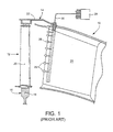
FIG. 1 is a partial cross-section of a turbine last stage in accordance with a known design, and showing a plurality of pressure probes located downstream of a turbine section; -
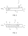
FIG. 2 is a side elevation, partly in section, showing a total-pressure probe in accordance with an exemplary but nonlimiting embodiment of the invention; -
FIG. 3 is a plan view of the pressure probe shown inFIG. 2 ; -
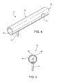
FIG. 4 is a perspective view of the probe shroud isolated fromFIGS. 2 and 3 ; -
FIG. 5 is a front-end view of the pressure probe shown inFIG 4 ; -
FIG. 6 is a perspective view of a probe as shown inFIGS. 2-5 installed in an instrument rake; and -
FIG. 7 is an enlarged detail taken fromFIG. 6 but from a different perspective. -
FIG. 1 is a simplified cross-section of a last- stage turbine section as described as disclosed inU.S. Pat. No. 4,433,584 , illustrating a known arrangement of a pressure probe rake located in the turbine exhaust. More specifically, the engine has a turbine section 10 (partially shown) and aflow path 12 for process gases which flow axially through the turbine section to the exhaust duct. Theturbine section 10 has astator assembly 14 and arotor assembly 16. The rotor assembly includes arotor disk 18 fitted with a plurality of radially-outwardly extending blades or buckets as represented by thesingle bucket 20. The stator assembly includes anouter casing 22 which circumscribes the turbine section and flow path. In this example, a plurality of stator struts 24 (one shown) extend radially inwardly from the outer casing across the flow path. Thestrut 24 has a plurality oftotal pressure probes 26 incorporated into the strut. Eachtotal pressure probe 26 is in fluid communication with atransducer 28 for converting total pressure levels into an analog or digital output. Eachprobe 26 includes apressure tube 30 extending between the tip of thepressure probe 26 and the transducer (only one shown for ease of understanding). - With reference now to
FIGS. 2-5 , a modified Kiel-type probe in according with an exemplary but nonlimiting embodiment of this invention is shown at 32. The probe comprisespressure tubing 34 having a remotepressure sensing tip 36, received with an enlarged, substantiallycylindrical shroud 38 through anaperture 40 in the shroud sidewall, and terminating proximate theforward opening 46 of the shroud. The otherwiseconventional sensing tip 36 of theprobe 32 is centered within theshroud 38 from a location slightly forward of theapertures 42, 44 (axially, as viewed inFig. 2 ) to a location just behind the apertures. Thetubing 34 is then routed within along the interior sidewall of the shroud as best appreciated fromFIGS. 2 and5 . Theapertures tip 36 of theprobe 32, theshroud 38. It will be understood that theprobe 32 could also extend through therearward end 48 of the shroud, depending on how the probe is attached to an associated rake or rake mast, described further below. - In the exemplary embodiment, the shroud may extend beyond the
sensing tip 36 of theprobe 32 about 0.19 inch and theapertures tip 36, such that the diametrical centers of the apertures are located about 0.38 inch behind theforward opening 46 of the shroud. As made apparent from the description above, theapertures pressure tubing 34 that is centered within the shroud. - By enlarging the diameter of the
shroud 38 and by providing larger-diameter drainage holes shroud 38 will pass through theapertures shroud 38 and exit the openrearward end 48, thereby preventing the development of water legs in thepressure tubing 34, and thus improving the accuracy of the pressure readings. -
FIGS. 6 and 7 show the probe/shroud assembly attached to arake mast 50 that allows the probe, and other similar probes (not shown), to be arranged at radially-spaced locations within or adjacent an inlet to a duct, similar to the arrangement inFIG. 1 . In a flow-through probe design, the open,rearward end 48 of theshroud 38 may pass through the rake mast 50 (seeFig. 6 ). In a closed design, the open,rearward end 48 of theshroud 38 is located within the rake mast, and any moisture flowing axially through and exiting theshroud 38 can exit the radially-inner end of therake mast 50. While the probe is shown extending at an angle of substantially ninety degrees relative to the mast, the angle may vary with specific applications. As in a conventional set-up, thesensing tip 36 faces opposite the flow direction through the duct. - In the exemplary but nonlimiting embodiment, the diameter of the shroud may be in the range of about 0.375-0.50 inch, as compared to a conventional diameter of 0.0625-0.25 inch, i.e., about twice the diameter of conventional probes. The wall thickness of the shroud may be, for example, about 0.07 inch. In the exemplary but nonlimiting embodiment, the
apertures - In addition, one or both of the
apertures - The described arrangement substantially inhibits if not eliminates the formation of water legs within the
pressure tubing 34, thereby enhancing the accuracy of the recorded pressure measurements. - It will be appreciated that the probe described herein is not limited to use or the turbine exhaust duct, but may also be used within the turbine air inlet.
- While the invention has been described in connection with what is presently considered to be the most practical and preferred embodiment, it is to be understood that the invention is not to be limited to the disclosed embodiment, but on the contrary, is intended to cover various modifications and equivalent arrangements included within the spirit and scope of the appended claims.
- Various aspects and embodiments of the present invention are defined by the following numbered clauses:
- 1. A pressure probe comprising:
- pressure tubing having a remote sending tip, said pressure tubing extending through an open-ended shroud, wherein said shroud has a diameter of at least about 0.375 to 0.50 inch; and wherein a forward end of said open-ended shroud is formed with at least two drainage apertures in proximity to said remote sensing tip.
- 2. The pressure probe of clause 1 wherein said at least two drainage apertures are substantially diametrically opposed.
- 3. The pressure probe of clause 1 or clause 2, wherein said at least two drainage apertures are substantially round.
- 4. The pressure probe of any preceding clause wherein each of said apertures has a diameter of between about 0.20 and 0.25.
- 5. The pressure probe of any preceding clause wherein said shroud is attached to a rake mast extending substantially 90° relative to said shroud.
- 6. The pressure probe of any preceding clause wherein said pressure tubing enters said shroud at a location proximate a rearward end of said shroud.
- 7. The pressure probe of any preceding clause wherein said shroud has an open rearward end, and said pressure tubing exits said shroud through an aperture proximate said open rearward end.
- 8. A pressure probe assembly for use in a turbine inlet or exhaust duct comprising:
- a rake mast adapted to extend substantially radially into the inlet or exhaust duct; and
- at least one pressure probe attached to said rake mast; wherein the pressure probe comprises a shroud; pressure tubing having a remote sending tip, said pressure tubing extending through said shroud; and wherein said shroud has a diameter of at least about 0.375 to 0.50 inch, and wherein a forward end of said shroud is formed with at least two drainage apertures in proximity to said remote sensing tip.
- 9. The pressure probe assembly of any preceding clause wherein said at least two drainage apertures are substantially diametrically opposed.
- 10. The pressure probe assembly of any preceding clause wherein said at least two drainage apertures are substantially round.
- 11. The pressure probe assembly of any preceding clause wherein each of said apertures has a diameter of between about 0.20 and 0.25.
- 12. The pressure probe assembly of any preceding clause wherein said shroud extends substantially perpendicularly relative to said rake mast.
- 13. The pressure probe assembly of any preceding clause wherein said pressure tubing enters said shroud at a location proximate a rearward end of said shroud.
- 14. The pressure probe assembly of any preceding clause wherein said shroud has an open rearward end, and said pressure tubing exits said shroud through an aperture proximate said open rearward end.
- 15. A pressure probe assembly for use in a turbine inlet or exhaust duct comprising:
- a rake mast adapted to extend substantially radially into the inlet or exhaust duct;
- at least one pressure probe attached to said rake mast; wherein the pressure probe comprises pressure tubing having a remote sending tip facing opposite a flow direction within the turbine inlet or exhaust duct, said pressure tubing extending through an open-ended shroud, wherein said open-ended shroud has a diameter of at least about 0.375 to 0.50 inch, and wherein a forward end of said open-ended shroud is formed with at least two drainage apertures in proximity to said remote sensing tip, said at least two drainage apertures having diameters ofbetween about 0.20 and 0.25 inch.
- 16. The pressure probe assembly of any preceding clause wherein a forward end portion of the pressure tubing is centered within the shroud, and another portion of the pressure tubing extends axially along an interior wall surface of the shroud.
- 17. The pressure probe assembly of any preceding clause wherein a sensing tip of the pressure tubing lies rearwardly of a forward open end of the shroud.
- 18. The pressure probe assembly of any preceding clause wherein said diameter of said drainage apertures is at least equal to an axial length of said forward end portion of said pressure tubing.
- 19. The pressure probe assembly of any preceding clause wherein an open rearward end of said shroud extends beyond said rake mast.
- 20. The pressure probe assembly of any preceding clause wherein said pressure tubing exits said shroud at a location axially-spaced from a rearward end of said shroud.
Claims (15)
- A pressure probe (32) comprising:pressure tubing (30) having a remote sending tip, said pressure tubing extending through an open-ended shroud, wherein said shroud has a diameter of at least about 0.375 to 0.50 inch; and wherein a forward end of said open-ended shroud is formed with at least two drainage apertures (42,44) in proximity to said remote sensing tip.
- The pressure probe of claim 1 wherein said at least two drainage apertures are substantially diametrically opposed.
- The pressure probe of claim 1 or claim 2, wherein said at least two drainage apertures are substantially round.
- The pressure probe of any preceding claim wherein each of said apertures has a diameter of between about 0.20 and 0.25 inches.
- The pressure probe of any preceding claim wherein said shroud is attached to a rake mast extending substantially 90° relative to said shroud.
- The pressure probe of any preceding claim wherein said pressure tubing enters said shroud at a location proximate a rearward end of said shroud.
- The pressure probe of any preceding claim wherein said shroud has an open rearward end, and said pressure tubing exits said shroud through an aperture proximate said open rearward end.
- A pressure probe assembly for use in a turbine inlet or exhaust duct comprising:a rake mast adapted to extend substantially radially into the inlet or exhaust duct; andat least one pressure probe according to any preceding claim attached to said rake mast; wherein the pressure probe comprises a shroud.
- The pressure probe assembly of claim 8 wherein said shroud extends substantially perpendicularly relative to said rake mast.
- A pressure probe assembly for use in a turbine inlet or exhaust duct comprising:a rake mast adapted to extend substantially radially into the inlet or exhaust duct;at least one pressure probe according to any preceding claim attached to said rake mast; wherein the remote sending tip faces opposite a flow direction within the turbine inlet or exhaust duct, and wherein said at least two drainage apertures have diameters of between about 0.20 and 0.25 inch.
- The pressure probe assembly of any of claims 8 to 10, wherein a forward end portion of the pressure tubing is centered within the shroud, and another portion of the pressure tubing extends axially along an interior wall surface of the shroud.
- The pressure probe assembly of any of claims 8 to 11, wherein a sensing tip of the pressure tubing lies rearwardly of a forward open end of the shroud.
- The pressure probe assembly of any of claims 8 to 12, wherein said diameter of said drainage apertures is at least equal to an axial length of said forward end portion of said pressure tubing.
- The pressure probe assembly of any of claims 8 to 13, wherein an open rearward end of said shroud extends beyond said rake mast.
- The pressure probe assembly of any of claims 8 to 14, wherein said pressure tubing exits said shroud at a location axially-spaced from a rearward end of said shroud.
Applications Claiming Priority (1)
| Application Number | Priority Date | Filing Date | Title |
|---|---|---|---|
| US13/430,001 US8863590B2 (en) | 2012-03-26 | 2012-03-26 | Large diameter flow-through Kiel-style pressure probe for high moisture applications |
Publications (1)
| Publication Number | Publication Date |
|---|---|
| EP2645074A2 true EP2645074A2 (en) | 2013-10-02 |
Family
ID=47913254
Family Applications (1)
| Application Number | Title | Priority Date | Filing Date |
|---|---|---|---|
| EP13160766.5A Withdrawn EP2645074A2 (en) | 2012-03-26 | 2013-03-25 | Large diameter flow-through kiel-style probe for high moisture applications |
Country Status (5)
| Country | Link |
|---|---|
| US (1) | US8863590B2 (en) |
| EP (1) | EP2645074A2 (en) |
| JP (1) | JP2013200310A (en) |
| CN (1) | CN103364131A (en) |
| RU (1) | RU2013112897A (en) |
Cited By (2)
| Publication number | Priority date | Publication date | Assignee | Title |
|---|---|---|---|---|
| EP3628825A1 (en) * | 2018-09-28 | 2020-04-01 | Rolls-Royce plc | Flow sensor rake assembly |
| AT528169A1 (en) * | 2024-04-04 | 2025-10-15 | Avl List Gmbh | Aerodynamic measuring grid |
Families Citing this family (5)
| Publication number | Priority date | Publication date | Assignee | Title |
|---|---|---|---|---|
| FR2959822B1 (en) * | 2010-05-07 | 2013-04-12 | Thales Sa | DEVICE FOR MONITORING A PRESSURE MEASURING PROBE OF A FLOW AND PROBE COMPRISING THE DEVICE |
| DE102015214443A1 (en) * | 2015-07-30 | 2017-02-02 | Siemens Aktiengesellschaft | Kiel probe |
| US10684183B2 (en) * | 2018-04-24 | 2020-06-16 | The Boeing Company | Powered total pressure measurement rake with telemetry |
| SE544928C2 (en) * | 2021-05-12 | 2023-01-10 | Isak Jonsson Ab | Multi-hole pressure probe and use of such a probe |
| CN121384309B (en) * | 2025-12-22 | 2026-02-17 | 大连温特纳科技有限公司 | A total pressure probe that reduces insensitivity angle limitations |
Family Cites Families (8)
| Publication number | Priority date | Publication date | Assignee | Title |
|---|---|---|---|---|
| US2397084A (en) * | 1943-12-11 | 1946-03-26 | Westinghouse Electric Corp | Method of manufacturing pitotstatic tubes |
| US4433584A (en) | 1981-11-27 | 1984-02-28 | United Technologies Corp. | Total pressure probe |
| US4730487A (en) * | 1985-06-04 | 1988-03-15 | Rosemount Inc. | Family of aerodynamically compensated multiple static pressure tubes |
| US4645517A (en) * | 1985-09-20 | 1987-02-24 | Rosemount Inc. | Drain manifold for air data sensor |
| US5046360A (en) * | 1989-12-15 | 1991-09-10 | Rosemount Inc. | Aerodynamic probe internal constructions |
| US5616861A (en) * | 1995-06-07 | 1997-04-01 | Rosemount Aerospace Inc. | Three pressure pseudo -Δ-P sensor for use with three pressure air data probe |
| US6591696B2 (en) * | 2001-07-12 | 2003-07-15 | Rosemount Aerospace, Inc. | Integral electric pressure probe for aircraft |
| US6892584B2 (en) * | 2002-11-19 | 2005-05-17 | Rosemount Aerospace Inc. | Fabricated pitot probe assembly |
-
2012
- 2012-03-26 US US13/430,001 patent/US8863590B2/en active Active
-
2013
- 2013-03-25 RU RU2013112897/28A patent/RU2013112897A/en not_active Application Discontinuation
- 2013-03-25 EP EP13160766.5A patent/EP2645074A2/en not_active Withdrawn
- 2013-03-25 JP JP2013061240A patent/JP2013200310A/en active Pending
- 2013-03-26 CN CN201310099475.6A patent/CN103364131A/en active Pending
Cited By (2)
| Publication number | Priority date | Publication date | Assignee | Title |
|---|---|---|---|---|
| EP3628825A1 (en) * | 2018-09-28 | 2020-04-01 | Rolls-Royce plc | Flow sensor rake assembly |
| AT528169A1 (en) * | 2024-04-04 | 2025-10-15 | Avl List Gmbh | Aerodynamic measuring grid |
Also Published As
| Publication number | Publication date |
|---|---|
| US8863590B2 (en) | 2014-10-21 |
| JP2013200310A (en) | 2013-10-03 |
| US20130247686A1 (en) | 2013-09-26 |
| RU2013112897A (en) | 2014-09-27 |
| CN103364131A (en) | 2013-10-23 |
Similar Documents
| Publication | Publication Date | Title |
|---|---|---|
| EP2645074A2 (en) | Large diameter flow-through kiel-style probe for high moisture applications | |
| US6772627B2 (en) | Flow vector analyzer for flow bench | |
| EP3290883B1 (en) | Temperature probe | |
| SE449266B (en) | PROCEDURE FOR SENSING TOTAL PRESSURE WITHOUT A TOTAL PRESSURE SUND | |
| CN111089702A (en) | Probe for measuring full parameters of subsonic three-dimensional steady-state flow field | |
| CN111140542B (en) | A tenon blade with three pressure-sensing holes on the leading edge of the primitive level | |
| US10126208B2 (en) | Sensor system having a sensor supported by a mast for use within fluid flows | |
| US20160266009A1 (en) | Probe | |
| März et al. | An experimental and numerical investigation into the mechanisms of rotating instability | |
| CN110043370B (en) | Air flow measuring method of turbofan engine core machine | |
| JP2011242389A (en) | Device and method for measuring internal clearances | |
| US10619506B2 (en) | Measuring total pressure of a fluid in a turbo machine | |
| US11480475B2 (en) | Method and system for measuring temperature in a gas turbine engine | |
| US20060042410A1 (en) | Humidity sensor protective shield | |
| KR101185999B1 (en) | Rake Module and Measuring Apparatus having the Same | |
| CN115371745A (en) | Non-intrusive engine air inlet flow tube based on contraction and expansion throat structure | |
| US20110082662A1 (en) | Method and device for detecting capacity changes in a fluid and turbine | |
| CN106768598B (en) | A Cylindrical Porous Total Pressure Probe for Measuring Total Pressure Between Blades along the Blade Height | |
| US9683909B2 (en) | Pressure-measuring device for measuring dynamic pressure and gas-turbine combustion chamber having pressure measuring device | |
| CN115435958B (en) | A device for measuring the flow field at the inlet and outlet of a fan | |
| CN211696880U (en) | Probe for measuring full parameters of subsonic three-dimensional steady-state flow field | |
| US4192178A (en) | Apparatus for determining stagnation pressure, static pressure, pitch angle, and yaw angle of elastic fluid | |
| CN212454963U (en) | A tenon-type blade with three pressure-sensing holes at the leading edge of the primitive level | |
| US20130098479A1 (en) | Gas Extractor for Exhaust Gas Monitoring | |
| Díaz et al. | Direct calibration framework of triple-hole pressure probes for incompressible flow |
Legal Events
| Date | Code | Title | Description |
|---|---|---|---|
| PUAI | Public reference made under article 153(3) epc to a published international application that has entered the european phase |
Free format text: ORIGINAL CODE: 0009012 |
|
| AK | Designated contracting states |
Kind code of ref document: A2 Designated state(s): AL AT BE BG CH CY CZ DE DK EE ES FI FR GB GR HR HU IE IS IT LI LT LU LV MC MK MT NL NO PL PT RO RS SE SI SK SM TR |
|
| AX | Request for extension of the european patent |
Extension state: BA ME |
|
| STAA | Information on the status of an ep patent application or granted ep patent |
Free format text: STATUS: THE APPLICATION IS DEEMED TO BE WITHDRAWN |
|
| 18D | Application deemed to be withdrawn |
Effective date: 20151001 |