EP2644915A1 - Constituent parts of a side seal for linear guide device, and linear guide device - Google Patents
Constituent parts of a side seal for linear guide device, and linear guide device Download PDFInfo
- Publication number
- EP2644915A1 EP2644915A1 EP11843600.5A EP11843600A EP2644915A1 EP 2644915 A1 EP2644915 A1 EP 2644915A1 EP 11843600 A EP11843600 A EP 11843600A EP 2644915 A1 EP2644915 A1 EP 2644915A1
- Authority
- EP
- European Patent Office
- Prior art keywords
- seal
- face
- lip
- linear guide
- seal member
- Prior art date
- Legal status (The legal status is an assumption and is not a legal conclusion. Google has not performed a legal analysis and makes no representation as to the accuracy of the status listed.)
- Withdrawn
Links
- 239000000470 constituent Substances 0.000 title 1
- 239000000463 material Substances 0.000 claims abstract description 7
- 238000005096 rolling process Methods 0.000 claims description 19
- 230000001154 acute effect Effects 0.000 claims description 3
- 238000007789 sealing Methods 0.000 abstract description 18
- 239000004519 grease Substances 0.000 description 7
- 210000002445 nipple Anatomy 0.000 description 7
- 238000010586 diagram Methods 0.000 description 4
- 230000007306 turnover Effects 0.000 description 4
- 239000002184 metal Substances 0.000 description 2
- 230000002542 deteriorative effect Effects 0.000 description 1
- 230000000694 effects Effects 0.000 description 1
- 238000005516 engineering process Methods 0.000 description 1
- 239000000314 lubricant Substances 0.000 description 1
Images




Classifications
-
- F—MECHANICAL ENGINEERING; LIGHTING; HEATING; WEAPONS; BLASTING
- F16—ENGINEERING ELEMENTS AND UNITS; GENERAL MEASURES FOR PRODUCING AND MAINTAINING EFFECTIVE FUNCTIONING OF MACHINES OR INSTALLATIONS; THERMAL INSULATION IN GENERAL
- F16C—SHAFTS; FLEXIBLE SHAFTS; ELEMENTS OR CRANKSHAFT MECHANISMS; ROTARY BODIES OTHER THAN GEARING ELEMENTS; BEARINGS
- F16C29/00—Bearings for parts moving only linearly
- F16C29/08—Arrangements for covering or protecting the ways
- F16C29/084—Arrangements for covering or protecting the ways fixed to the carriage or bearing body movable along the guide rail or track
- F16C29/086—Seals being essentially U-shaped, e.g. for a U-shaped carriage
-
- F—MECHANICAL ENGINEERING; LIGHTING; HEATING; WEAPONS; BLASTING
- F16—ENGINEERING ELEMENTS AND UNITS; GENERAL MEASURES FOR PRODUCING AND MAINTAINING EFFECTIVE FUNCTIONING OF MACHINES OR INSTALLATIONS; THERMAL INSULATION IN GENERAL
- F16C—SHAFTS; FLEXIBLE SHAFTS; ELEMENTS OR CRANKSHAFT MECHANISMS; ROTARY BODIES OTHER THAN GEARING ELEMENTS; BEARINGS
- F16C29/00—Bearings for parts moving only linearly
- F16C29/04—Ball or roller bearings
- F16C29/06—Ball or roller bearings in which the rolling bodies circulate partly without carrying load
- F16C29/0633—Ball or roller bearings in which the rolling bodies circulate partly without carrying load with a bearing body defining a U-shaped carriage, i.e. surrounding a guide rail or track on three sides
-
- F—MECHANICAL ENGINEERING; LIGHTING; HEATING; WEAPONS; BLASTING
- F16—ENGINEERING ELEMENTS AND UNITS; GENERAL MEASURES FOR PRODUCING AND MAINTAINING EFFECTIVE FUNCTIONING OF MACHINES OR INSTALLATIONS; THERMAL INSULATION IN GENERAL
- F16C—SHAFTS; FLEXIBLE SHAFTS; ELEMENTS OR CRANKSHAFT MECHANISMS; ROTARY BODIES OTHER THAN GEARING ELEMENTS; BEARINGS
- F16C33/00—Parts of bearings; Special methods for making bearings or parts thereof
- F16C33/72—Sealings
- F16C33/76—Sealings of ball or roller bearings
-
- F—MECHANICAL ENGINEERING; LIGHTING; HEATING; WEAPONS; BLASTING
- F16—ENGINEERING ELEMENTS AND UNITS; GENERAL MEASURES FOR PRODUCING AND MAINTAINING EFFECTIVE FUNCTIONING OF MACHINES OR INSTALLATIONS; THERMAL INSULATION IN GENERAL
- F16C—SHAFTS; FLEXIBLE SHAFTS; ELEMENTS OR CRANKSHAFT MECHANISMS; ROTARY BODIES OTHER THAN GEARING ELEMENTS; BEARINGS
- F16C2240/00—Specified values or numerical ranges of parameters; Relations between them
- F16C2240/30—Angles, e.g. inclinations
- F16C2240/34—Contact angles
Definitions
- the present invention relates to side seals fixed to both ends of a slider, in an actuation direction thereof, constituting a linear guide apparatus.
- the linear guide apparatus is an apparatus which includes a guide rail, the slider, and a plurality of rolling elements.
- the guide rail and the slider are disposed so as to face with each other and have therebetween rolling surfaces, respectively, that constitute a rolling channel for the rolling elements, and the rolling elements roll over such a rolling channel so that one of the guide rail and the slider takes a linear motion with respect to the other.
- FIG. 12 A conventional example of a linear guide apparatus is shown in FIG. 12 .
- This linear guide apparatus includes a guide rail 100, a slider (also referred to as "bearing") 200, and a plurality of rollers (rolling elements) 300.
- the guide rail 100 and the slider 200 are disposed so as to face with each other and have therebetween rolling surfaces 110 and 210, respectively, which constitute a rolling channel for the rollers 300.
- the slider 200 can be divided into a slider main body 201, end caps 202 fixed to both ends of the slider main body, and side seals 203 further fixed to both ends of the slider main body in the lengthwise direction of the guide rail 100.
- the rolling surfaces 210 are formed in the slider main body 201.
- the side seals 203 disposed at both ends in the linear-motion direction of the slider 102 have respective lips each sealing spaces between the slider 200 and the top face of the guide rail 100 and between the slider and both side faces of the guide rail 100.
- the slider 200 also has return channels 221 for the rollers 300 and turn-over channels 222 which cause respective return channels 221 and respective rolling channels to be communicated with each other.
- the return channels 221 are formed in the slider main body 201 and the turn-over channels 222 are formed in each end cap 202.
- Female screws 205 which enable attachment of a table, etc , by means of screws are formed in the top face of the slider 200.
- Attachment holes for a grease nipple 400 are formed in the side seals 203 and the end caps 202.
- a lubricant is introduced to an oil path of the end cap 202 through the grease nipple 400, so that the linear guide apparatus is lubricated.
- the side seals 203 and the end caps 202 are fixed to the slider main body 201 by bolts 500..
- Attachment holes 120 for enabling attachment of the guide rail 100 to a mounting object like a base by means of bolts are formed in the guide rail 100.
- a circulation channel for the rolling elements is formed with the rolling channel, the return channel, and the turn-over channel.
- the rollers 300 circulate in the circulation channel, thereby allowing one of the guide rail 100 and the slider 200 to take a linear motion with respect to the other.
- An example conventional side seal for such a linear guide apparatus has a metal plate and a rubber-made seal member having a base fixed on the metal holder plate. The lip of the seal member is brought into contact with the top face of the guide rail and both side faces thereof when in use.
- Patent Document 1 discloses a technology that the holder plate (a casing) of the side seal and the seal member (a seal) with a lip (a sealing lip) are formed of different members, and a scraper which is disposed so as to face the external face of the guide rail with a gap from such an external face is provided at the opposite side of the holder plate for the seal member.
- the holder plate and the seal are engaged with each other by fitting of a protrusion and a recess. According to such a side seal, relatively large foreign materials are repelled by the scraper at first, and thus the sealing lip can have a longer life and an improved action.
- Patent Document 2 discloses a side seal (a scraper) that includes two seal members having respective lips (the sealing lips) inclined in opposite directions to each other, a piece of supporting plate which supports such seal members, and a housing having recesses which receive the bases of such seal members and the supporting plate.
- This side seal employs the above-explained structure in order to enable replacement of the seal members without a detachment of the whole slider (a guide carriage) from the guide rail (a guiding rail) Moreover, the supporting plate employs a structure which can support the side seal without deteriorating the function of the side seal in both cases in which the supporting plate supports the two seal members and in which the supporting plate supports only one seal member that is formed of a flexible material.
- Patent Documents 1 and 2 leave much for an improvement of the sealing performance by changing the sealing function depending on its application. It is an object of the present invention to provide a side seal for a linear guide apparatus which includes, as constituting components, a seal member, a holder plate that holds the seal member, and a cover (a scraper), and which can improve the sealing performance by the side seal by changing the sealing function depending on its application.
- a constituting component of a side seal for a linear guide apparatus comprising a guide rail, the slider, and a plurality of rolling elements, in which the side seals are fixed to both ends of a slider in an actuation direction, the constituting component of the side seal for the linear guide apparatus comprising following configurations (1) to (4).
- multiple seal members among the above-explained plural types of the seal members are appropriately selected, and are used in combination with the same number of the covers and the same number of the holder plates, so that the side seal having a different sealing function depending on its application can be assembled.
- a side seal for a linear guide apparatus of the present invention multiple numbers of seal members among the above-explained plural types of the seal members are appropriately selected, and the side seal is constituted by a combination of the same number of covers and the same number of holder plates, thereby improving the sealing performance by the side seal by changing the sealing function depending on its application.
- Side-seal constituting components according to the present embodiment can constitute a side seal 203 for the above-explained linear guide apparatus shown in FIG 12 , and multiple numbers of respective seal members 1, holder plates 2, and covers 3 are prepared which are formed to have a shape shown in FIG. 1 . Multiple numbers of the seal members 1 of different types are prepared, and multiple numbers of respective holder plates 2 and covers 3 of the same type are also prepared.
- the seal member 1 can be divided into an upper seal portion 1a to be disposed above a guide rail 100 (see FIG. 12 ), and side seal portions 1b to be disposed at right and left sides of the guide rail 100, respectively, when its arrangement is viewed from the front.
- the seal member 1 can also be divided into a lip 11 in contact with the top face of the guide rail and both side faces thereof, and a base 12 to be held by the holder plate 2 with the seal portions 1a and 1b being disposed so as to face the guide rail.
- FIGS. 3A to 3F are each corresponding to a cross-sectional view taken along a line A-A in FIG. 2 .
- a base 12 of each of the seal members 1A to 1F has a recess (an engaging portion to be engaged with the holder plate 2 by fitting of a protrusion and a recess) 12a formed to have a first face 13 in the thickness direction.
- a recess 12a divides the base 12 into a tip 12b and a base end 12c.
- Lips 11a to 11f of the seal members 1A to 1F are formed at the tips 12b of respective bases 12, and are inclined in the thickness direction from the first face 13 side toward a second face 14 side of the bases 12
- a third face 15 that is the outermost (the side separated from the guide rail) surface of each of the seal members 1A to 1F is orthogonal to the first and second faces 13 and 14 of the base end 12c
- the first seal member 1A shown in FIG. 3A is a standard seal member, and is formed in such a way that the inclination of the lip 11a relative to the face of the guide rail has substantially 20 degrees.
- a tip face of the lip 11a is so formed as to be orthogonal to the inclination direction of the lip 11a.
- the second seal member 1B shown in FIG. 3B has the lip 11b thicker than the lip 11a of the first seal member 1A, and is formed in such a way that the inclination of the lip 11b relative to the face of the guide rail is the same as that of the lip 11a of the first seal member 1A. Moreover, a tip face of the lip 11b is so formed as to be orthogonal to the inclination direction of the lip 11b.
- the third seal member 1C shown in FIG. 3C has the lip 11c in the same thickness as that of the lip 11a of the first seal member 1A, and is formed in such a way that the inclination of the lip 11c relative to the face of the guide rail has substantially 30 degrees. Moreover, a tip face of the lip 11c is so formed as to be orthogonal to the inclination direction of the lip 11c.
- the fourth seal member 1D shown in FIG. 3D has the lip 11d in the same thickness as that of the lip 11a of the first seal member 1A, and is formed in such a way that the inclination of the lip 11d relative to the face of the guide rail has substantially 40 degrees. Moreover, a tip face of the lip 11d is so formed as to be orthogonal to the inclination direction of the lip 11d.
- the fifth seal member 1E shown in FIG. 3E has the lip 11e in the same thickness as that of the lip 11a of the first seal member 1A, and is formed in such a way that the inclination of the lip 11e relative to the face of the guide rail has substantially 30 degrees. Moreover, a tip face of the lip 11e is so formed as to be obtuse (substantially 110 degrees) relative to the inclination direction of the lip 11e.
- the sixth seal member 1F shown in FIG. 3F has the lip 11f in the same thickness as that of the lip 11a of the first seal member 1A, and is formed in such a way that the inclination of the lip 11f relative to the face of the guide rail has substantially 20 degrees Moreover, a tip face of the lip 11f is so formed as to be acute (substantially 80 degrees) relative to the inclination direction of the lip 11f.
- the holder plate 2 has a face formed to have a substantially same shape as that of the end cap 202 (see FIG. 12 ) constituting the slider 200 (see FIG. 12 ), and includes an upper portion 2a to be disposed above the guide rail 100 and side portions 2b to be disposed at right and left sides of the guide rail 100, respectively.
- Through holes 52 which allow the bolts 500 (see FIG. 12 ) to pass through, and a through hole 42 for attaching a grease nipple 400 (see FIG. 12 ) are formed in the upper portion 2a.
- the through holes 52 which allow the bolts 500 to pass through are also formed in respective side portions 2b.
- a holding portion 20 which holds the base 12 of the seal member 1 is formed at the inside (the guide rail side) of the holder plate 2.
- the holding portion 20 includes a protrusion 21 to be fitted in the recess 12a of the base 12 of the seal member 1, a first holding face 22 formed at the inside of the protrusion 21, a second holding face 23 formed at the outside of the protrusion 21, and a third holding face 24 formed at the outside of the second holding face 23.
- the first holding face 22 and the second holding face 23 are parallel to the tabular face of the holder plate 2, and the third holding face 24 is orthogonal to the tabular face of the holder plate 2
- the cover 3 has a face formed to have a substantially same shape as that of the end cap 202 constituting the slider 200, and includes an upper member 31 facing with the top face of the guide rail with a gap therebetween, and side members 32 facing with right and left side faces of the guide rail 100, respectively, with a gap therebetween.
- Through holes 53 which allow the bolts 500 to pass through, and a through hole 43 for attaching the grease nipple 400 are formed in the upper member 31.
- the through holes 53 which allow the bolts 500 to pass through are also formed in respective side members 32.
- the side-seal constituting components multiple seal members among the seal members 1A to 1F are appropriately selected to be used in combination with the same number of the holder plates 2 and the same number of the covers 3, so that the side seal having different sealing functions depending on its application can be assembled.
- the side seal 203 shown in FIG. 6 and FIG. 7 can be assembled by using the two holder plates 2 and covers 3, the first seal member 1A, and the second seal member 1B.
- the first seal member 1A and the second seal member 1B have lips 11a and 11b with different thicknesses and disposed in such a way that the lips 11a and 11b are inclined in opposite directions separated from each other.
- the seal members 1A and 1B are held by the holder plates 2, respectively.
- the base end 12c is fitted in the recess formed by the third holding face 24, the second holding face 23, and the surface of the protrusion 21 facing with the third holding face 24.
- the two holder plates 2 holding the seal members 1A and 1B are disposed with the surfaces opposite to the holding portions 20 facing with each other, respectively, and the covers 3 are disposed on the surfaces at the seal member 1A side and the seal member 1B side Accordingly, the side seal 203 can be assembled.
- Such side seals 203 are, as shown in FIG. 8 , attached to each of both ends of the slider 200 in the actuation direction thereof which constitutes the linear guide apparatus. According to such side seals 203, the lip 11b of the second seal member 1B disposed at the inside and the lip 11a of the first seal member 1A disposed at the outside accomplish different sealing functions, thereby accomplishing good sealing performance and dust-proof performance.
- the side seals 203 which have the third seal members 1C and the fourth seal members 1D disposed in such a way that the lips 11c and 11d are inclined in opposite directions separated from each other are attached to both ends of the slider 200 in the actuation direction thereof.
- the contact pressure to the guide rail 100 by the lip 11d of the fourth seal member 1D disposed at the inside is larger than that of the lip 11c of the third seal member 1C disposed at the outside.
- the side seals 203 have the three holder plates 2 and three covers 3 and the three first seal members 1A.
- Individual seal members 1A are disposed in such a way that the lips 11a are inclined inwardly, inwardly, and outwardly in this order from the slider 200 side
- Such side seals are attached to both ends of the slider 200 in the actuation direction thereof.
- a further improved sealing performance can be obtained.
- the side seals 203 which have the fifth seal members 1E and the sixth seal members 1F disposed in such a way that the lips 11e and 11f are inclined in opposite directions separated from each other are attached to both ends of the slider 200 in the actuation direction thereof.
- the lip 11f of the sixth seal member 1F disposed at the inside and the lip 11e of the fifth seal member 1E disposed at the outside accomplish different sealing functions.
- seal members 1A to 1F which have a difference in at least any one of the inclination, the thickness, and the tip shape of the lip are prepared, the seal members which are in the same shape but have a difference in materials only may be prepared.
Landscapes
- Engineering & Computer Science (AREA)
- General Engineering & Computer Science (AREA)
- Mechanical Engineering (AREA)
- Bearings For Parts Moving Linearly (AREA)
Abstract



Description
- The present invention relates to side seals fixed to both ends of a slider, in an actuation direction thereof, constituting a linear guide apparatus. The linear guide apparatus is an apparatus which includes a guide rail, the slider, and a plurality of rolling elements. The guide rail and the slider are disposed so as to face with each other and have therebetween rolling surfaces, respectively, that constitute a rolling channel for the rolling elements, and the rolling elements roll over such a rolling channel so that one of the guide rail and the slider takes a linear motion with respect to the other.
- A conventional example of a linear guide apparatus is shown in
FIG. 12 . This linear guide apparatus includes aguide rail 100, a slider (also referred to as "bearing") 200, and a plurality of rollers (rolling elements) 300. Theguide rail 100 and theslider 200 are disposed so as to face with each other and have therebetweenrolling surfaces rollers 300. - The
slider 200 can be divided into a slidermain body 201,end caps 202 fixed to both ends of the slider main body, andside seals 203 further fixed to both ends of the slider main body in the lengthwise direction of theguide rail 100. Therolling surfaces 210 are formed in the slidermain body 201. Theside seals 203 disposed at both ends in the linear-motion direction of the slider 102 have respective lips each sealing spaces between theslider 200 and the top face of theguide rail 100 and between the slider and both side faces of theguide rail 100. - The
slider 200 also hasreturn channels 221 for therollers 300 and turn-overchannels 222 which causerespective return channels 221 and respective rolling channels to be communicated with each other. Thereturn channels 221 are formed in the slidermain body 201 and the turn-overchannels 222 are formed in eachend cap 202.Female screws 205 which enable attachment of a table, etc , by means of screws are formed in the top face of theslider 200. - Attachment holes for a
grease nipple 400 are formed in theside seals 203 and theend caps 202. A lubricant is introduced to an oil path of theend cap 202 through thegrease nipple 400, so that the linear guide apparatus is lubricated. Theside seals 203 and theend caps 202 are fixed to the slidermain body 201 bybolts 500..Attachment holes 120 for enabling attachment of theguide rail 100 to a mounting object like a base by means of bolts are formed in theguide rail 100. - According to this linear guide apparatus, a circulation channel for the rolling elements is formed with the rolling channel, the return channel, and the turn-over channel. The
rollers 300 circulate in the circulation channel, thereby allowing one of theguide rail 100 and theslider 200 to take a linear motion with respect to the other.
An example conventional side seal for such a linear guide apparatus has a metal plate and a rubber-made seal member having a base fixed on the metal holder plate. The lip of the seal member is brought into contact with the top face of the guide rail and both side faces thereof when in use. -
Patent Document 1 discloses a technology that the holder plate (a casing) of the side seal and the seal member (a seal) with a lip (a sealing lip) are formed of different members, and a scraper which is disposed so as to face the external face of the guide rail with a gap from such an external face is provided at the opposite side of the holder plate for the seal member. The holder plate and the seal are engaged with each other by fitting of a protrusion and a recess. According to such a side seal, relatively large foreign materials are repelled by the scraper at first, and thus the sealing lip can have a longer life and an improved action. -
Patent Document 2 discloses a side seal (a scraper) that includes two seal members having respective lips (the sealing lips) inclined in opposite directions to each other, a piece of supporting plate which supports such seal members, and a housing having recesses which receive the bases of such seal members and the supporting plate. - This side seal employs the above-explained structure in order to enable replacement of the seal members without a detachment of the whole slider (a guide carriage) from the guide rail (a guiding rail) Moreover, the supporting plate employs a structure which can support the side seal without deteriorating the function of the side seal in both cases in which the supporting plate supports the two seal members and in which the supporting plate supports only one seal member that is formed of a flexible material.
-
- Patent Document 1:
JP 2007-211900 A - Patent Document 2:
JP 2008-528895 A - The side seals of
Patent Documents
It is an object of the present invention to provide a side seal for a linear guide apparatus which includes, as constituting components, a seal member, a holder plate that holds the seal member, and a cover (a scraper), and which can improve the sealing performance by the side seal by changing the sealing function depending on its application. - To accomplish the object above, according to a first aspect of the present invention, there is provided a constituting component of a side seal for a linear guide apparatus comprising a guide rail, the slider, and a plurality of rolling elements, in which the side seals are fixed to both ends of a slider in an actuation direction, the constituting component of the side seal for the linear guide apparatus comprising following configurations (1) to (4).
-
- (1) wherein the constituting component comprises:
- a cover including an upper member and side members facing with a top face of the guide rail and both side faces thereof, respectively, with gaps;
- a seal member including a lip in contact with the top face and both side faces of the guide rail, and a base; and
- a holder plate that holds the base;
- (2) wherein the base includes an engaging portion formed in one face of the seal member in a thickness direction and engaged with the holder plate by fitting of a protrusion and a recess, the lip is inclined from the one face toward another face in the thickness direction, and the cover is disposed on the another face of the seal member in the thickness direction in contact with the another face of the seal member;
-
- (3) wherein a plurality of the covers having a same shape are prepared, a plurality of the holder plates having a same shape are prepared, and plural types of the seal members having a difference in at least any one of an inclination, a material, a thickness, and a tip shape of the lip are prepared; and
- (4) wherein a plurality of the covers, a plurality of the holder plates, and a plurality of the seal members are combined together when in use.
- According to the constituting component of the side seal for the linear guide apparatus according to the present invention, multiple seal members among the above-explained plural types of the seal members are appropriately selected, and are used in combination with the same number of the covers and the same number of the holder plates, so that the side seal having a different sealing function depending on its application can be assembled.
- According to the constituting components of a side seal for a linear guide apparatus of the present invention, multiple numbers of seal members among the above-explained plural types of the seal members are appropriately selected, and the side seal is constituted by a combination of the same number of covers and the same number of holder plates, thereby improving the sealing performance by the side seal by changing the sealing function depending on its application.
-
-
FIG.. 1 is a perspective view showing constituting components of a side seal which are a seal member, a holder plate, and a cover according to an embodiment; -
FIG. 2 is a front view showing the seal member according to an embodiment; -
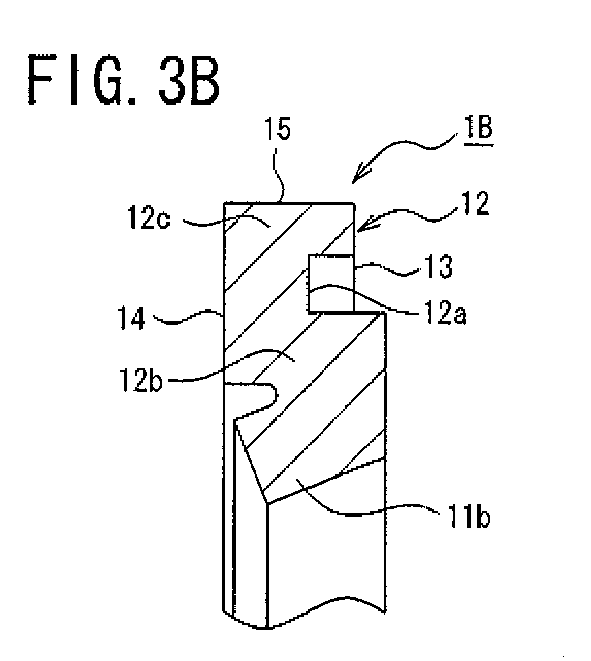
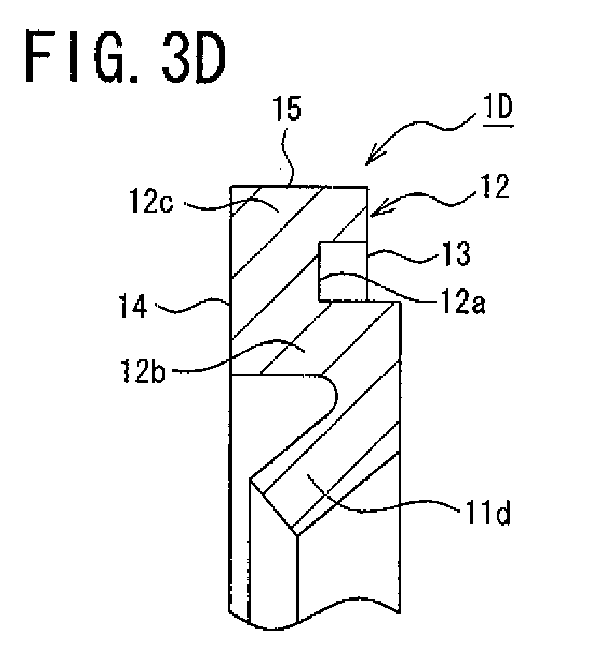
FIGS. 3A to 3F are cross-sectional views (corresponding to a cross-sectional view taken along a line A-A inFIG.. 2 ) showing plural types of the seal members according to an embodiment; -
FIG. 4 is a front view showing the holder plate according to an embodiment; -
FIG. 5 is a cross-sectional view taken along a line B-B inFIG. 4 ; -
FIG. 6 is a front view showing the assembled side seal according to an embodiment; -
FIG. 7 is a cross-sectional view taken along a line C-C inFIG. 6 ; -
FIG. 8 is a schematic structural diagram showing a linear guide apparatus to which the side seals each assembled using a first seal member and a second seal member are attached; -
FIG. 9 is a schematic structural diagram showing a linear guide apparatus to which the side seals each assembled using a third seal member and a fourth seal member are attached; -
FIG. 10 is a schematic structural diagram showing a linear guide apparatus to which the side seals each assembled using the three first seal members are attached; -
FIG. 11 is a schematic structural diagram showing a linear guide apparatus to which the side seals each assembled using a fifth seal member and a sixth seal member are attached; and -
FIG 12 is a partially sectional perspective view showing a conventional example of a linear guide apparatus. - Embodiments of the present invention will now be described with reference to the accompanying drawings.
Side-seal constituting components according to the present embodiment can constitute aside seal 203 for the above-explained linear guide apparatus shown inFIG 12 , and multiple numbers ofrespective seal members 1,holder plates 2, andcovers 3 are prepared which are formed to have a shape shown inFIG. 1 . Multiple numbers of theseal members 1 of different types are prepared, and multiple numbers ofrespective holder plates 2 and covers 3 of the same type are also prepared. - As shown in
FIG. 2 , theseal member 1 can be divided into anupper seal portion 1a to be disposed above a guide rail 100 (seeFIG. 12 ), andside seal portions 1b to be disposed at right and left sides of theguide rail 100, respectively, when its arrangement is viewed from the front. Theseal member 1 can also be divided into alip 11 in contact with the top face of the guide rail and both side faces thereof, and a base 12 to be held by theholder plate 2 with theseal portions - Six types of
seal members 1A to 1F shown inFIGS. 3A to 3F are prepared as such aseal member 1.FIGS. 3A to 3F are each corresponding to a cross-sectional view taken along a line A-A inFIG. 2 .
As shown in those figures, abase 12 of each of theseal members 1A to 1F has a recess (an engaging portion to be engaged with theholder plate 2 by fitting of a protrusion and a recess) 12a formed to have afirst face 13 in the thickness direction. Such arecess 12a divides the base 12 into atip 12b and abase end 12c. -
Lips 11a to 11f of theseal members 1A to 1F are formed at thetips 12b ofrespective bases 12, and are inclined in the thickness direction from thefirst face 13 side toward asecond face 14 side of the bases 12 Athird face 15 that is the outermost (the side separated from the guide rail) surface of each of theseal members 1A to 1F is orthogonal to the first and second faces 13 and 14 of thebase end 12c
Thefirst seal member 1A shown inFIG. 3A is a standard seal member, and is formed in such a way that the inclination of thelip 11a relative to the face of the guide rail has substantially 20 degrees. Moreover, a tip face of thelip 11a is so formed as to be orthogonal to the inclination direction of thelip 11a. - The
second seal member 1B shown inFIG. 3B has thelip 11b thicker than thelip 11a of thefirst seal member 1A, and is formed in such a way that the inclination of thelip 11b relative to the face of the guide rail is the same as that of thelip 11a of thefirst seal member 1A. Moreover, a tip face of thelip 11b is so formed as to be orthogonal to the inclination direction of thelip 11b.
Thethird seal member 1C shown inFIG. 3C has thelip 11c in the same thickness as that of thelip 11a of thefirst seal member 1A, and is formed in such a way that the inclination of thelip 11c relative to the face of the guide rail has substantially 30 degrees. Moreover, a tip face of thelip 11c is so formed as to be orthogonal to the inclination direction of thelip 11c. - The
fourth seal member 1D shown inFIG. 3D has thelip 11d in the same thickness as that of thelip 11a of thefirst seal member 1A, and is formed in such a way that the inclination of thelip 11d relative to the face of the guide rail has substantially 40 degrees. Moreover, a tip face of thelip 11d is so formed as to be orthogonal to the inclination direction of thelip 11d.
Thefifth seal member 1E shown inFIG. 3E has thelip 11e in the same thickness as that of thelip 11a of thefirst seal member 1A, and is formed in such a way that the inclination of thelip 11e relative to the face of the guide rail has substantially 30 degrees. Moreover, a tip face of thelip 11e is so formed as to be obtuse (substantially 110 degrees) relative to the inclination direction of thelip 11e. - The
sixth seal member 1F shown inFIG. 3F has thelip 11f in the same thickness as that of thelip 11a of thefirst seal member 1A, and is formed in such a way that the inclination of thelip 11f relative to the face of the guide rail has substantially 20 degrees Moreover, a tip face of thelip 11f is so formed as to be acute (substantially 80 degrees) relative to the inclination direction of thelip 11f. - As shown in
FIG. 4 and FIG. 5 , theholder plate 2 has a face formed to have a substantially same shape as that of the end cap 202 (seeFIG. 12 ) constituting the slider 200 (seeFIG. 12 ), and includes anupper portion 2a to be disposed above theguide rail 100 andside portions 2b to be disposed at right and left sides of theguide rail 100, respectively. Throughholes 52 which allow the bolts 500 (seeFIG. 12 ) to pass through, and a throughhole 42 for attaching a grease nipple 400 (seeFIG. 12 ) are formed in theupper portion 2a. The through holes 52 which allow thebolts 500 to pass through are also formed inrespective side portions 2b. A holdingportion 20 which holds thebase 12 of theseal member 1 is formed at the inside (the guide rail side) of theholder plate 2. - The holding
portion 20 includes aprotrusion 21 to be fitted in therecess 12a of thebase 12 of theseal member 1, a first holdingface 22 formed at the inside of theprotrusion 21, asecond holding face 23 formed at the outside of theprotrusion 21, and a third holdingface 24 formed at the outside of the second holdingface 23. The first holdingface 22 and the second holdingface 23 are parallel to the tabular face of theholder plate 2, and the third holdingface 24 is orthogonal to the tabular face of theholder plate 2 - As shown in
FIG. 1 andFIG. 6 , thecover 3 has a face formed to have a substantially same shape as that of theend cap 202 constituting theslider 200, and includes anupper member 31 facing with the top face of the guide rail with a gap therebetween, andside members 32 facing with right and left side faces of theguide rail 100, respectively, with a gap therebetween. Throughholes 53 which allow thebolts 500 to pass through, and a throughhole 43 for attaching thegrease nipple 400 are formed in theupper member 31. The through holes 53 which allow thebolts 500 to pass through are also formed inrespective side members 32. - According to the side-seal constituting components according to the present embodiment, multiple seal members among the
seal members 1A to 1F are appropriately selected to be used in combination with the same number of theholder plates 2 and the same number of thecovers 3, so that the side seal having different sealing functions depending on its application can be assembled.
For example, theside seal 203 shown inFIG. 6 and FIG. 7 can be assembled by using the twoholder plates 2 and covers 3, thefirst seal member 1A, and thesecond seal member 1B. According to such aside seal 203, thefirst seal member 1A and thesecond seal member 1B havelips lips - More specifically, as shown in
FIG. 7 , by fitting therecesses 12a of thebases 12 of theseal members protrusions 21 of the holdingportions 20 of theholder plates 2, respectively, theseal members holder plates 2, respectively. At this time, thebase end 12c is fitted in the recess formed by the third holdingface 24, the second holdingface 23, and the surface of theprotrusion 21 facing with the third holdingface 24. Moreover, the twoholder plates 2 holding theseal members portions 20 facing with each other, respectively, and thecovers 3 are disposed on the surfaces at theseal member 1A side and theseal member 1B side Accordingly, theside seal 203 can be assembled. - Such side seals 203 are, as shown in
FIG. 8 , attached to each of both ends of theslider 200 in the actuation direction thereof which constitutes the linear guide apparatus. According to such side seals 203, thelip 11b of thesecond seal member 1B disposed at the inside and thelip 11a of thefirst seal member 1A disposed at the outside accomplish different sealing functions, thereby accomplishing good sealing performance and dust-proof performance. - According to the linear guide apparatus shown in
FIG. 9 , the side seals 203 which have thethird seal members 1C and thefourth seal members 1D disposed in such a way that thelips slider 200 in the actuation direction thereof. In this case, the contact pressure to theguide rail 100 by thelip 11d of thefourth seal member 1D disposed at the inside is larger than that of thelip 11c of thethird seal member 1C disposed at the outside. - According to the linear guide apparatus shown in
FIG. 10 , the side seals 203 have the threeholder plates 2 and threecovers 3 and the threefirst seal members 1A.Individual seal members 1A are disposed in such a way that thelips 11a are inclined inwardly, inwardly, and outwardly in this order from theslider 200 side Such side seals are attached to both ends of theslider 200 in the actuation direction thereof. In this case, by using the threeseal members 1A, a further improved sealing performance can be obtained. - According to the linear guide apparatus shown in
FIG. 11 , the side seals 203 which have thefifth seal members 1E and thesixth seal members 1F disposed in such a way that thelips slider 200 in the actuation direction thereof. In this case, thelip 11f of thesixth seal member 1F disposed at the inside and thelip 11e of thefifth seal member 1E disposed at the outside accomplish different sealing functions. - According to this embodiment, although six types of
seal members 1A to 1F which have a difference in at least any one of the inclination, the thickness, and the tip shape of the lip are prepared, the seal members which are in the same shape but have a difference in materials only may be prepared. -
- 1
- Seal member
- 1A to 1F
- First to sixth seal members
- 1a
- Upper seal portion
- 1b
- Side seal portion
- 11
- Lip
- 11a to 11f
- Lips of first to sixth seal members
- 12
- Base
- 12a
- Recess of base (engaging portion)
- 12b
- Tip of base
- 12c
- Base end
- 13
- First face of base
- 14
- Second face of base
- 15
- Third face of base
- 2
- Holder plate
- 2a
- Upper portion of holder plate
- 2b
- Side portion of holder plate
- 20
- Holding portion
- 21
- Convexity
- 22
- First holding face
- 23
- Second holding face
- 24
- Third holding face
- 3
- Cover
- 31
- Upper member of cover
- 32
- Side member of cover
- 42
- Through hole for attaching grease nipple
- 43
- Through hole for attaching grease nipple
- 52
- Through hole for allowing bolt to pass through
- 53
- Through hole for allowing bolt to pass through
- 100
- Guide rail
- 110
- Rolling surface of guide rail
- 200
- Slider
- 201
- Slider main body
- 202
- End cap
- 203
- Side seal
- 205
- Female screw
- 210
- Rolling surface of slider
- 221
- Return channel
- 222
- Turn-over channel
- 300
- Roller (rolling element)
- 400
- Grease nipple
- 500
- Bolt
Claims (8)
- A constituting component of a side seal for a linear guide apparatus comprising a guide rail, the slider, and a plurality of rolling elements, in which the side seals are fixed to both ends of a slider in an actuation direction, the constituting component of the side seal for the linear guide apparatus comprising following configurations (1) to (4):(1) wherein the constituting component comprises:a cover including an upper member and side members facing with a top face of the guide rail and both side faces thereof, respectively, with gaps;a seal member including a lip in contact with the top face and both side faces of the guide rail, and a base; anda holder plate that holds the base;(2) wherein the base includes an engaging portion formed in one face of the seal member in a thickness direction and engaged with the holder plate by fitting of a protrusion and a recess, the lip is inclined from the one face toward another face in the thickness direction, and the cover is disposed on the another face of the seal member in the thickness direction in contact with the another face of the seal member;(3) wherein a plurality of the covers having a same shape are prepared, a plurality of the holder plates having a same shape are prepared, and plural types of the seal members having a difference in at least any one of an inclination, a material, a thickness, and a tip shape of the lip are prepared; and(4) wherein a plurality of the covers, a plurality of the holder plates, and a plurality of the seal members are combined together when in use.
- The constituting component of the side seal for the linear guide apparatus according to claim 1, wherein a plurality of types of the seal members have lips with an inclination angle of substantially 20 degrees, substantially 30 degrees, and substantially 40 degrees relative to a face of the guide rail.
- The constituting component of the side seal for the linear guide apparatus according to claim 1, wherein the lips of the plurality of types of the seal members have tip faces so formed as to be orthogonal, obtuse, and acute relative to inclination directions of respective lips.
- A linear guide apparatus comprising a guide rail, a slider, a plurality of rolling elements, and side seals fixed to both ends of the slider in an actuation direction thereof, the constituting component of the side seals comprising following configurations (1) to (4):(1) wherein the constituting component comprises:a cover including an upper member and side members facing with a top face of the guide rail and both side faces thereof, respectively, with gaps;a seal member including a lip in contact with the top face and both side faces of the guide rail, and a base; anda holder plate that holds the base;(2) wherein the base includes an engaging portion formed in one face of the seal member in a thickness direction and engaged with the holder plate by fitting of a protrusion and a recess, the lip is inclined from the one face toward another face in the thickness direction, and the cover is disposed on the another face of the seal member in the thickness direction in contact with the another face of the seal member;(3) wherein a plurality of the covers having a same shape are prepared, a plurality of the holder plates having a same shape are prepared, and plural types of the seal members having a difference in at least any one of an inclination, a material, a thickness, and a tip shape of the lip are prepared; and(4) wherein a plurality of the covers, a plurality of the holder plates, and a plurality of the seal members are combined together when in use.
- The linear guide apparatus according to claim 4, wherein:the side seal comprises the two seal members including lips with a different thickness, and the two holder plates and the two covers, andthe two seal members are disposed in such a way that the lips are inclined in opposite directions separated from each other.
- The linear guide apparatus according to claim 4, wherein:the side seal comprises the two seal members including lips with a different inclination angle relative to a face of the guide rail, and the two holder plates and the two covers, andthe two seal members are disposed in such a way that lips are inclined in opposite directions separated from each other.
- The linear guide apparatus according to claim 4, wherein:the side seal comprises the three holder plates, the three covers, and the three seal members, andthe three seal members are disposed in such a way that lips are inclined inwardly, inwardly, and outwardly in this order from a slider side
- The linear guide apparatus according to claim 4, wherein:the side seal comprises:the seal member including the lip having a tip face formed so as to be obtuse relative to an inclination direction of the lip;the seal member including the lip having a tip face formed so as to be acute relative to the inclination direction of the lip;the two holder plates; andthe two covers, andthe two seal members are disposed in such a way that lips are inclined in opposite directions separated from each other.
Applications Claiming Priority (2)
| Application Number | Priority Date | Filing Date | Title |
|---|---|---|---|
| JP2010261164 | 2010-11-24 | ||
| PCT/JP2011/005848 WO2012070185A1 (en) | 2010-11-24 | 2011-10-19 | Constituent parts of a side seal for linear guide device, and linear guide device |
Publications (2)
| Publication Number | Publication Date |
|---|---|
| EP2644915A1 true EP2644915A1 (en) | 2013-10-02 |
| EP2644915A4 EP2644915A4 (en) | 2016-03-16 |
Family
ID=46145559
Family Applications (1)
| Application Number | Title | Priority Date | Filing Date |
|---|---|---|---|
| EP11843600.5A Withdrawn EP2644915A4 (en) | 2010-11-24 | 2011-10-19 | Constituent parts of a side seal for linear guide device, and linear guide device |
Country Status (5)
| Country | Link |
|---|---|
| US (1) | US8985856B2 (en) |
| EP (1) | EP2644915A4 (en) |
| JP (1) | JP5682630B2 (en) |
| CN (1) | CN102667196B (en) |
| WO (1) | WO2012070185A1 (en) |
Families Citing this family (4)
| Publication number | Priority date | Publication date | Assignee | Title |
|---|---|---|---|---|
| WO2013029903A1 (en) * | 2011-09-01 | 2013-03-07 | Rausch & Pausch Gmbh | Seal, and control device having said seal |
| JP6295624B2 (en) | 2012-12-04 | 2018-03-20 | 日本精工株式会社 | Side guide for linear guide, linear guide |
| JP6340778B2 (en) | 2012-12-04 | 2018-06-13 | 日本精工株式会社 | Linear guide device |
| DE102018201885A1 (en) * | 2018-02-07 | 2019-08-08 | Aktiebolaget Skf | Sealed storage module |
Family Cites Families (13)
| Publication number | Priority date | Publication date | Assignee | Title |
|---|---|---|---|---|
| JP2596055Y2 (en) * | 1992-12-24 | 1999-06-07 | 株式会社ツバキ・ナカシマ | Dustproof seal device for linear motion guide bearing |
| JP3331280B2 (en) * | 1995-07-31 | 2002-10-07 | 日本トムソン株式会社 | Linear motion rolling guide unit |
| JP3308944B2 (en) * | 1998-12-04 | 2002-07-29 | テイエチケー株式会社 | Dust-proof structure of guide device |
| JP2003314548A (en) * | 2002-04-25 | 2003-11-06 | Keeper Co Ltd | Seal body for linear bearing |
| US7467796B2 (en) * | 2004-08-12 | 2008-12-23 | Morgan Construction, Company | Bearing seal with flexible lip |
| DE102005003874A1 (en) | 2005-01-27 | 2006-08-03 | Schaeffler Kg | Linear roller bearing e.g. for automotive industry for engines, transmissions and powertrains, has guide carriage mounted to roll along guide rail and scraper located on end face of guide carriage for scraping foreign bodies |
| DE102005003711A1 (en) * | 2005-01-27 | 2006-08-17 | Schaeffler Kg | linear bearings |
| JP2007211900A (en) | 2006-02-09 | 2007-08-23 | Nsk Ltd | End seal and linear motion guide device including the same |
| JP2008138843A (en) * | 2006-12-05 | 2008-06-19 | Nsk Ltd | Linear guide device |
| JP5089455B2 (en) | 2008-03-26 | 2012-12-05 | 日本トムソン株式会社 | Linear motion guidance unit |
| US8387990B2 (en) * | 2008-09-09 | 2013-03-05 | Trelleborg Sealing Solutions Americas | Seal assembly |
| DE102009046975B4 (en) * | 2009-11-23 | 2021-08-19 | Robert Bosch Gmbh | Sealing ring, especially for a hydraulic piston pump |
| JP2012052609A (en) * | 2010-09-01 | 2012-03-15 | Nsk Ltd | Linear motion guide device |
-
2011
- 2011-10-19 JP JP2012545601A patent/JP5682630B2/en active Active
- 2011-10-19 EP EP11843600.5A patent/EP2644915A4/en not_active Withdrawn
- 2011-10-19 WO PCT/JP2011/005848 patent/WO2012070185A1/en not_active Ceased
- 2011-10-19 US US13/989,072 patent/US8985856B2/en active Active
- 2011-10-19 CN CN201180002192.4A patent/CN102667196B/en active Active
Also Published As
| Publication number | Publication date |
|---|---|
| WO2012070185A1 (en) | 2012-05-31 |
| EP2644915A4 (en) | 2016-03-16 |
| JP5682630B2 (en) | 2015-03-11 |
| CN102667196A (en) | 2012-09-12 |
| US8985856B2 (en) | 2015-03-24 |
| US20130251291A1 (en) | 2013-09-26 |
| JPWO2012070185A1 (en) | 2014-05-19 |
| CN102667196B (en) | 2015-09-02 |
Similar Documents
| Publication | Publication Date | Title |
|---|---|---|
| EP2642146B1 (en) | Side seal for linear guide device, and linear guide device | |
| EP2634442B1 (en) | Side rail for linear guide device and linear guide device | |
| US9051966B2 (en) | Linear guide apparatus | |
| US8985856B2 (en) | Side seal for linear guide apparatus and linear guide apparatus | |
| US10612591B2 (en) | Linear guide device | |
| US8632248B2 (en) | Linear guide device | |
| CN103814225B (en) | Linear guide device | |
| CN104204567B (en) | Linear guide device | |
| EP2930383B1 (en) | Side seal for linear guide and linear guide | |
| JP2013164118A (en) | Side seal for linear guide device, and linear guide device | |
| JP2014101911A (en) | Side seal for linear guide device | |
| JP5817190B2 (en) | Side guide for linear guide device | |
| JP2015178841A (en) | Side seal of linear guide device | |
| JP2016183742A (en) | Side seal of linear motion guide device, linear motion guide device | |
| JP2006170418A (en) | Linear motion guide bearing device | |
| JP2006170417A (en) | Linear motion guide bearing device |
Legal Events
| Date | Code | Title | Description |
|---|---|---|---|
| PUAI | Public reference made under article 153(3) epc to a published international application that has entered the european phase |
Free format text: ORIGINAL CODE: 0009012 |
|
| 17P | Request for examination filed |
Effective date: 20130528 |
|
| AK | Designated contracting states |
Kind code of ref document: A1 Designated state(s): AL AT BE BG CH CY CZ DE DK EE ES FI FR GB GR HR HU IE IS IT LI LT LU LV MC MK MT NL NO PL PT RO RS SE SI SK SM TR |
|
| DAX | Request for extension of the european patent (deleted) | ||
| RA4 | Supplementary search report drawn up and despatched (corrected) |
Effective date: 20160215 |
|
| RIC1 | Information provided on ipc code assigned before grant |
Ipc: F16C 29/08 20060101ALI20160209BHEP Ipc: F16C 33/78 20060101ALI20160209BHEP Ipc: F16C 29/06 20060101ALN20160209BHEP Ipc: F16C 29/04 20060101AFI20160209BHEP |
|
| STAA | Information on the status of an ep patent application or granted ep patent |
Free format text: STATUS: THE APPLICATION HAS BEEN WITHDRAWN |
|
| 18W | Application withdrawn |
Effective date: 20160905 |