EP2644896A2 - Liquid metal pump for chemical reactor heating circuit - Google Patents
Liquid metal pump for chemical reactor heating circuit Download PDFInfo
- Publication number
- EP2644896A2 EP2644896A2 EP20120461540 EP12461540A EP2644896A2 EP 2644896 A2 EP2644896 A2 EP 2644896A2 EP 20120461540 EP20120461540 EP 20120461540 EP 12461540 A EP12461540 A EP 12461540A EP 2644896 A2 EP2644896 A2 EP 2644896A2
- Authority
- EP
- European Patent Office
- Prior art keywords
- pump
- liquid metal
- rotor
- inflow
- collector
- Prior art date
- Legal status (The legal status is an assumption and is not a legal conclusion. Google has not performed a legal analysis and makes no representation as to the accuracy of the status listed.)
- Withdrawn
Links
- 229910001338 liquidmetal Inorganic materials 0.000 title claims abstract description 26
- 238000010438 heat treatment Methods 0.000 title claims abstract description 11
- 239000000126 substance Substances 0.000 title claims abstract description 8
- 239000002184 metal Substances 0.000 claims abstract description 9
- 229910052751 metal Inorganic materials 0.000 claims abstract description 9
- 230000001681 protective effect Effects 0.000 claims description 9
- 239000000463 material Substances 0.000 description 4
- RYGMFSIKBFXOCR-UHFFFAOYSA-N Copper Chemical compound [Cu] RYGMFSIKBFXOCR-UHFFFAOYSA-N 0.000 description 2
- 238000001816 cooling Methods 0.000 description 2
- 229910052802 copper Inorganic materials 0.000 description 2
- 239000010949 copper Substances 0.000 description 2
- 238000000034 method Methods 0.000 description 2
- 239000013502 plastic waste Substances 0.000 description 2
- 230000003628 erosive effect Effects 0.000 description 1
- 238000009434 installation Methods 0.000 description 1
- 239000012528 membrane Substances 0.000 description 1
- 150000002739 metals Chemical class 0.000 description 1
- 238000011084 recovery Methods 0.000 description 1
Images

Classifications
-
- F—MECHANICAL ENGINEERING; LIGHTING; HEATING; WEAPONS; BLASTING
- F04—POSITIVE - DISPLACEMENT MACHINES FOR LIQUIDS; PUMPS FOR LIQUIDS OR ELASTIC FLUIDS
- F04D—NON-POSITIVE-DISPLACEMENT PUMPS
- F04D7/00—Pumps adapted for handling specific fluids, e.g. by selection of specific materials for pumps or pump parts
- F04D7/02—Pumps adapted for handling specific fluids, e.g. by selection of specific materials for pumps or pump parts of centrifugal type
- F04D7/06—Pumps adapted for handling specific fluids, e.g. by selection of specific materials for pumps or pump parts of centrifugal type the fluids being hot or corrosive, e.g. liquid metals
- F04D7/065—Pumps adapted for handling specific fluids, e.g. by selection of specific materials for pumps or pump parts of centrifugal type the fluids being hot or corrosive, e.g. liquid metals for liquid metal
-
- F—MECHANICAL ENGINEERING; LIGHTING; HEATING; WEAPONS; BLASTING
- F04—POSITIVE - DISPLACEMENT MACHINES FOR LIQUIDS; PUMPS FOR LIQUIDS OR ELASTIC FLUIDS
- F04D—NON-POSITIVE-DISPLACEMENT PUMPS
- F04D1/00—Radial-flow pumps, e.g. centrifugal pumps; Helico-centrifugal pumps
- F04D1/006—Radial-flow pumps, e.g. centrifugal pumps; Helico-centrifugal pumps double suction pumps
Definitions
- the presently disclosed subject matter relates to rotor - type liquid metal pump for realization of chemical reactor heating circuit, for example for realization of continuous heat transport process within the process of plastic waste material depolymerisation for component recovery.
- Liquid metal mechanical pumps described in another patent specifications are designed as submersible and are used for periodical operation consisting of transferring of liquid metal between tanks or to moulds, as for example in invention specifications US2010196151 , CN101363691 , KR20090126368 , CA2538556 , MXPA05004332 , US2001000465 , W02004040143 , utility pattern specifications CN201666260 , CN202157970 , CN201335021 , CN2890429 or patent specifications US6439860 , US6345964 , JP4874243 .
- Body of the pump for chemical reactor heating system has inflow chambers from both sides of the rotor ensuring heating medium circulation.
- Liquid metal is fed to inflow chambers by means of at least two-way collector.
- Collector sections are chosen to maintain quantitative balance of liquid metal fed into both inflow chambers.
- Each collector arm is introduced into an inflow chamber in favourably tangent way, causing whirl of metal stream according to rotor sense of rotation.
- Pump body is provided with favourably top and bottom inflow chambers for liquid metal.
- One of those inflow chambers is provided with flange for fitting of pump shaft protective sheath of length greater than level of liquid metal in the tank, from which it is flowing into the pump and in this sheath a protective atmosphere is maintained between instantaneous level of liquid metal and the seal of rotor drive shaft.
- Pump according to the present invention is characterized by a much lower failure frequency comparing to pumps used previously for liquid metal in the metallurgical industry. Balanced feeding of the pump significantly extends the lifetime of bearing shells, and also lifetime of the pump operated in chemical reactor heating system.
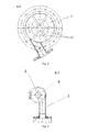
- Example of embodiment of the present subject matter is depicted in Figures 1 to 3 , where vertical section of the pump is depicted in Fig. 1 , section of the pump in the rotor plane is depicted in Fig. 2 and top view in horizontal section is depicted in Fig. 3 .
- the pump is provided with connecting pipe 1 passing into two-way collector 2 for liquid metal inflow from the kettle, two inflow chambers, located over 3 and under 3a pump body, feeding liquid metal from both sides of the rotor 9 .
- Each of both parts of inflow collector 2 is connected to generatrix of chambers 3 and 3a in favourably tangent direction, in the way causing whirl of metal stream according to rotor sense of rotation.
- liquid metal is introduced in a way bypassing rotor axle.
- inflow openings 11 are provided, through which liquid metal can inflow in axial direction from both sides, along pump shaft 6 , among rotor blades.
- Material of cover 4 and pump body 8 existing between openings 11 holds in a position bearing shell seats 7 of rotor shaft.
- Material of bearing shells does not contain copper because of most of metals used for heat transport wash out copper from bearing shells causing their erosion and fast wear.
- Outflow pipe 10 of pumped metal is led tangentially to the body of rotor chamber.
- Protective sheath 12 of rotor shaft is fitted to the flange 5 . Height of protective sheath 12 is greater than level of liquid metal in the kettle, from which it is flowing into the pump. Protective atmosphere is maintained between metal level in this sheath and shaft seal.
Landscapes
- Engineering & Computer Science (AREA)
- Mechanical Engineering (AREA)
- General Engineering & Computer Science (AREA)
- Structures Of Non-Positive Displacement Pumps (AREA)
Abstract
Description
- The presently disclosed subject matter relates to rotor - type liquid metal pump for realization of chemical reactor heating circuit, for example for realization of continuous heat transport process within the process of plastic waste material depolymerisation for component recovery.
- Pumps for liquid metal used as heating medium are up to now described in patent literature essentially exclusively as components of nuclear fast reactor cooling systems or processor cooling systems. There are however mostly of electromagnetic type and using a mechanical pump, as in patent specification
JP2009243285 US2010196151 ,CN101363691 ,KR20090126368 CA2538556 ,MXPA05004332 US2001000465 ,W02004040143 , utility pattern specificationsCN201666260 ,CN202157970 ,CN201335021 ,CN2890429 or patent specificationsUS6439860 ,US6345964 ,JP4874243 PL205686 - On the basis of data obtained from tests carried out in industrial conditions a liquid metal pump was designed providing many weeks of continuous operation in chemical reactor heating system.
- Body of the pump for chemical reactor heating system has inflow chambers from both sides of the rotor ensuring heating medium circulation. Liquid metal is fed to inflow chambers by means of at least two-way collector. Collector sections are chosen to maintain quantitative balance of liquid metal fed into both inflow chambers. Each collector arm is introduced into an inflow chamber in favourably tangent way, causing whirl of metal stream according to rotor sense of rotation. Pump body is provided with favourably top and bottom inflow chambers for liquid metal. One of those inflow chambers is provided with flange for fitting of pump shaft protective sheath of length greater than level of liquid metal in the tank, from which it is flowing into the pump and in this sheath a protective atmosphere is maintained between instantaneous level of liquid metal and the seal of rotor drive shaft.
- Pump according to the present invention is characterized by a much lower failure frequency comparing to pumps used previously for liquid metal in the metallurgical industry. Balanced feeding of the pump significantly extends the lifetime of bearing shells, and also lifetime of the pump operated in chemical reactor heating system.
- Example of embodiment of the present subject matter is depicted in
Figures 1 to 3 , where vertical section of the pump is depicted inFig. 1 , section of the pump in the rotor plane is depicted inFig. 2 and top view in horizontal section is depicted inFig. 3 . - The pump is provided with connecting
pipe 1 passing into two-way collector 2 for liquid metal inflow from the kettle, two inflow chambers, located over 3 and under 3a pump body, feeding liquid metal from both sides of therotor 9. Each of both parts ofinflow collector 2 is connected to generatrix ofchambers 3 and 3a in favourably tangent direction, in the way causing whirl of metal stream according to rotor sense of rotation. In other words, liquid metal is introduced in a way bypassing rotor axle. In pump body cover 4 and in bottom ofrotor chamber 8inflow openings 11 are provided, through which liquid metal can inflow in axial direction from both sides, alongpump shaft 6, among rotor blades. Material of cover 4 andpump body 8 existing betweenopenings 11 holds in a position bearing shell seats 7 of rotor shaft. Material of bearing shells does not contain copper because of most of metals used for heat transport wash out copper from bearing shells causing their erosion and fast wear.Outflow pipe 10 of pumped metal is led tangentially to the body of rotor chamber.Protective sheath 12 of rotor shaft is fitted to theflange 5. Height ofprotective sheath 12 is greater than level of liquid metal in the kettle, from which it is flowing into the pump. Protective atmosphere is maintained between metal level in this sheath and shaft seal. - Before starting the pump levels of the metal in the
protective sheath 12 and in the kettle are equal. In the moment of turning the pump on the level in the protective sheath starts lowering until such a difference of levels will appear which ensures metal inflow to the pump in the amount compensating delivery of the pump. In other words those level difference generates pressure enabling overcoming of pipe resistance of connection between the kettle and the pump at given rate of delivery of the pump.
Claims (5)
- Liquid metal pump for chemical reactor heating circuit equipped with rotor to provide circulation of heating medium, characterized in that the body of the pump (8) has inflow chambers (3,3 a) on both sides of the rotor (9), to which with at least two-way manifold (2) liquid metal is provided.
- Pump according to claim 1, characterized in that sections of the collector (2) are chosen to maintain quantitative balance of liquid metal fed into both inflow chambers (3,3a).
- Pump according to claim 2, characterized in that each arm of collector (2) is introduced to inflow chamber (3) and inflow chamber (3a) in favourably tangent way, causing whirl of metal stream according to sense of rotation of rotor (9).
- Pump according to claim 1, characterized in that pump body (8) is provided with top (3) and bottom (3a) liquid metal inflow chamber.
- Pump according to claim 1, characterized in that inflow chamber (3) is equipped with flange (5) for fitting of protective sheath (12) of pump shaft (6) of length greater than the level of liquid metal in the tank, from which it inflows to the pump, ant that in this sheath a protective atmosphere is maintained between instantaneous level of liquid metal and the seal of rotor drive shaft.
Applications Claiming Priority (1)
| Application Number | Priority Date | Filing Date | Title |
|---|---|---|---|
| PL398669A PL220603B1 (en) | 2012-03-31 | 2012-03-31 | Liquid metal pump for the chemical reactor heating circuit |
Publications (1)
| Publication Number | Publication Date |
|---|---|
| EP2644896A2 true EP2644896A2 (en) | 2013-10-02 |
Family
ID=47191684
Family Applications (1)
| Application Number | Title | Priority Date | Filing Date |
|---|---|---|---|
| EP20120461540 Withdrawn EP2644896A2 (en) | 2012-03-31 | 2012-09-07 | Liquid metal pump for chemical reactor heating circuit |
Country Status (2)
| Country | Link |
|---|---|
| EP (1) | EP2644896A2 (en) |
| PL (1) | PL220603B1 (en) |
Citations (16)
| Publication number | Priority date | Publication date | Assignee | Title |
|---|---|---|---|---|
| US20010000465A1 (en) | 1999-02-04 | 2001-04-26 | Thut Bruno H. | Pumps for pumping molten metal |
| US6345964B1 (en) | 1996-12-03 | 2002-02-12 | Paul V. Cooper | Molten metal pump with metal-transfer conduit molten metal pump |
| US6439860B1 (en) | 1999-11-22 | 2002-08-27 | Karl Greer | Chambered vane impeller molten metal pump |
| WO2004040143A1 (en) | 2002-10-29 | 2004-05-13 | Pyrotek, Inc. | Molten metal pump system |
| MXPA05004332A (en) | 2002-10-29 | 2005-08-03 | Pyrotek Inc | Molten metal pump system. |
| CA2538556A1 (en) | 2005-03-07 | 2006-09-07 | Bruno Thut | Multi functional pump for pumping molten metal |
| CN2890429Y (en) | 2006-04-30 | 2007-04-18 | 南京云海特种金属股份有限公司 | Magnesium alloy suckback pump |
| CN101363691A (en) | 2007-06-21 | 2009-02-11 | 保罗·V·库珀 | Transfer molten metal from one structure to another |
| JP2009243285A (en) | 2008-03-28 | 2009-10-22 | Hitachi-Ge Nuclear Energy Ltd | Liquid metal pump for fast breeder reactor |
| CN201335021Y (en) | 2008-12-01 | 2009-10-28 | 太原恒瑞镁技术开发有限公司 | Magnesium alloy liquid transferring pump |
| KR20090126368A (en) | 2008-06-04 | 2009-12-09 | 주식회사 포미니 시스템 | Metal pump of continuous galvanizing equipment |
| PL205686B1 (en) | 2005-02-25 | 2010-05-31 | Adam Handerek | Installation designed for thermal depolymerization of plastic wastes and method for the thermal depolymerization of plastic wastes |
| US20100196151A1 (en) | 2002-07-12 | 2010-08-05 | Cooper Paul V | Protective coatings for molten metal devices |
| CN201666260U (en) | 2010-03-08 | 2010-12-08 | 王道红 | Novel vertical type melting alkali pump |
| JP4874243B2 (en) | 2004-07-07 | 2012-02-15 | パイロテック インコーポレイテッド | Molten metal pump |
| CN202157970U (en) | 2010-04-07 | 2012-03-07 | Zmag株式会社 | Non-ferrous metal melting pump and melting furnace system using the metal pump |
-
2012
- 2012-03-31 PL PL398669A patent/PL220603B1/en unknown
- 2012-09-07 EP EP20120461540 patent/EP2644896A2/en not_active Withdrawn
Patent Citations (16)
| Publication number | Priority date | Publication date | Assignee | Title |
|---|---|---|---|---|
| US6345964B1 (en) | 1996-12-03 | 2002-02-12 | Paul V. Cooper | Molten metal pump with metal-transfer conduit molten metal pump |
| US20010000465A1 (en) | 1999-02-04 | 2001-04-26 | Thut Bruno H. | Pumps for pumping molten metal |
| US6439860B1 (en) | 1999-11-22 | 2002-08-27 | Karl Greer | Chambered vane impeller molten metal pump |
| US20100196151A1 (en) | 2002-07-12 | 2010-08-05 | Cooper Paul V | Protective coatings for molten metal devices |
| MXPA05004332A (en) | 2002-10-29 | 2005-08-03 | Pyrotek Inc | Molten metal pump system. |
| WO2004040143A1 (en) | 2002-10-29 | 2004-05-13 | Pyrotek, Inc. | Molten metal pump system |
| JP4874243B2 (en) | 2004-07-07 | 2012-02-15 | パイロテック インコーポレイテッド | Molten metal pump |
| PL205686B1 (en) | 2005-02-25 | 2010-05-31 | Adam Handerek | Installation designed for thermal depolymerization of plastic wastes and method for the thermal depolymerization of plastic wastes |
| CA2538556A1 (en) | 2005-03-07 | 2006-09-07 | Bruno Thut | Multi functional pump for pumping molten metal |
| CN2890429Y (en) | 2006-04-30 | 2007-04-18 | 南京云海特种金属股份有限公司 | Magnesium alloy suckback pump |
| CN101363691A (en) | 2007-06-21 | 2009-02-11 | 保罗·V·库珀 | Transfer molten metal from one structure to another |
| JP2009243285A (en) | 2008-03-28 | 2009-10-22 | Hitachi-Ge Nuclear Energy Ltd | Liquid metal pump for fast breeder reactor |
| KR20090126368A (en) | 2008-06-04 | 2009-12-09 | 주식회사 포미니 시스템 | Metal pump of continuous galvanizing equipment |
| CN201335021Y (en) | 2008-12-01 | 2009-10-28 | 太原恒瑞镁技术开发有限公司 | Magnesium alloy liquid transferring pump |
| CN201666260U (en) | 2010-03-08 | 2010-12-08 | 王道红 | Novel vertical type melting alkali pump |
| CN202157970U (en) | 2010-04-07 | 2012-03-07 | Zmag株式会社 | Non-ferrous metal melting pump and melting furnace system using the metal pump |
Also Published As
| Publication number | Publication date |
|---|---|
| PL220603B1 (en) | 2015-11-30 |
| PL398669A1 (en) | 2013-10-14 |
Similar Documents
| Publication | Publication Date | Title |
|---|---|---|
| US8714910B2 (en) | Compressor unit and assembly method | |
| CN201187473Y (en) | Residual heat discharge pump for nuclear power station | |
| CN209278142U (en) | Diving high-efficiency double suction pump | |
| EP3223285A1 (en) | Pump for pumping smelt | |
| CN105090051A (en) | Shielded electric pump | |
| EP2644896A2 (en) | Liquid metal pump for chemical reactor heating circuit | |
| JP6447491B2 (en) | Vertical sinking type centrifugal pump and repair method of vertical sinking type centrifugal pump | |
| CN102213219A (en) | Novel fluoroplastic alloy chemical centrifugal pump | |
| JP6395477B2 (en) | Underwater bearing structure and vertical shaft pump | |
| CN106930970A (en) | A kind of Insulation Shell of Magnet Pump of two-layer composite engineering plastics | |
| RU92921U1 (en) | CENTRIFUGAL MULTI-STAGE PUMP | |
| RU2413876C1 (en) | Stage of downhole multistage rotary pump | |
| CN204003628U (en) | The integrated cooling unit of bearing and mechanical seal | |
| RU153798U1 (en) | SUBMERSIBLE TYPE PUMP FOR TRANSFER OF LIQUID METALS OF NUCLEAR POWER PLANTS | |
| CN212867936U (en) | IHF type fluoroplastic reinforced alloy chemical centrifugal pump | |
| CN110081017A (en) | A kind of impeller of proof submersible sand discharging pump | |
| CN207740244U (en) | A kind of pump and pump group part of variable installation direction | |
| JP6569580B2 (en) | Management method of vertical sinking type centrifugal pump and management system of vertical sinking type centrifugal pump | |
| CN206830500U (en) | A kind of Insulation Shell of Magnet Pump of two-layer composite engineering plastics | |
| CN211328380U (en) | Fixing device and filter | |
| Grötsch et al. | Inside the canned motor centrifugal pump | |
| US12359668B2 (en) | Mold pump engagement apparatus | |
| CN202705429U (en) | Pilot-plant for recycling valuable metal from electroplating sludge | |
| Bolade et al. | Design of Centrifugal Pump for High Temperature Fluid | |
| CN213839003U (en) | Aluminum water circulating pump impeller |
Legal Events
| Date | Code | Title | Description |
|---|---|---|---|
| PUAI | Public reference made under article 153(3) epc to a published international application that has entered the european phase |
Free format text: ORIGINAL CODE: 0009012 |
|
| AK | Designated contracting states |
Kind code of ref document: A2 Designated state(s): AL AT BE BG CH CY CZ DE DK EE ES FI FR GB GR HR HU IE IS IT LI LT LU LV MC MK MT NL NO PL PT RO RS SE SI SK SM TR |
|
| AX | Request for extension of the european patent |
Extension state: BA ME |
|
| 17P | Request for examination filed |
Effective date: 20140324 |
|
| RBV | Designated contracting states (corrected) |
Designated state(s): AL AT BE BG CH CY CZ DE DK EE ES FI FR GB GR HR HU IE IS IT LI LT LU LV MC MK MT NL NO PL PT RO RS SE SI SK SM TR |
|
| STAA | Information on the status of an ep patent application or granted ep patent |
Free format text: STATUS: THE APPLICATION IS DEEMED TO BE WITHDRAWN |
|
| 18D | Application deemed to be withdrawn |
Effective date: 20150401 |