EP2644842A2 - Rotor and wheel cooling assembly for a steam turbine system - Google Patents
Rotor and wheel cooling assembly for a steam turbine system Download PDFInfo
- Publication number
- EP2644842A2 EP2644842A2 EP13161177.4A EP13161177A EP2644842A2 EP 2644842 A2 EP2644842 A2 EP 2644842A2 EP 13161177 A EP13161177 A EP 13161177A EP 2644842 A2 EP2644842 A2 EP 2644842A2
- Authority
- EP
- European Patent Office
- Prior art keywords
- rotor
- cooling
- flow
- wheel
- cooling assembly
- Prior art date
- Legal status (The legal status is an assumption and is not a legal conclusion. Google has not performed a legal analysis and makes no representation as to the accuracy of the status listed.)
- Withdrawn
Links
- 238000001816 cooling Methods 0.000 title claims abstract description 143
- 239000000126 substance Substances 0.000 claims description 28
- 238000010276 construction Methods 0.000 description 2
- 230000008878 coupling Effects 0.000 description 2
- 238000010168 coupling process Methods 0.000 description 2
- 238000005859 coupling reaction Methods 0.000 description 2
- 230000000694 effects Effects 0.000 description 2
- 230000003993 interaction Effects 0.000 description 2
- 238000011144 upstream manufacturing Methods 0.000 description 2
- 230000004075 alteration Effects 0.000 description 1
- 238000013459 approach Methods 0.000 description 1
- 230000000712 assembly Effects 0.000 description 1
- 238000000429 assembly Methods 0.000 description 1
- 239000007767 bonding agent Substances 0.000 description 1
- 238000010438 heat treatment Methods 0.000 description 1
- 238000000034 method Methods 0.000 description 1
- 238000012856 packing Methods 0.000 description 1
- 230000008569 process Effects 0.000 description 1
- 239000002994 raw material Substances 0.000 description 1
- 230000003068 static effect Effects 0.000 description 1
- 238000006467 substitution reaction Methods 0.000 description 1
- 238000003466 welding Methods 0.000 description 1
Images


Classifications
-
- F—MECHANICAL ENGINEERING; LIGHTING; HEATING; WEAPONS; BLASTING
- F01—MACHINES OR ENGINES IN GENERAL; ENGINE PLANTS IN GENERAL; STEAM ENGINES
- F01D—NON-POSITIVE DISPLACEMENT MACHINES OR ENGINES, e.g. STEAM TURBINES
- F01D25/00—Component parts, details, or accessories, not provided for in, or of interest apart from, other groups
- F01D25/08—Cooling; Heating; Heat-insulation
- F01D25/12—Cooling
-
- F—MECHANICAL ENGINEERING; LIGHTING; HEATING; WEAPONS; BLASTING
- F05—INDEXING SCHEMES RELATING TO ENGINES OR PUMPS IN VARIOUS SUBCLASSES OF CLASSES F01-F04
- F05D—INDEXING SCHEME FOR ASPECTS RELATING TO NON-POSITIVE-DISPLACEMENT MACHINES OR ENGINES, GAS-TURBINES OR JET-PROPULSION PLANTS
- F05D2220/00—Application
- F05D2220/30—Application in turbines
- F05D2220/31—Application in turbines in steam turbines
Definitions
- the subject matter disclosed herein relates generally to steam turbine systems, and more particularly to an assembly for cooling a rotor therein.
- Steam turbines typically include static nozzle assemblies that direct steam into rotating buckets that are connected to a rotor. A plurality of diaphragm stages or nozzle assembly stages is included and each stage is assembled around the rotor. Select sections of the steam turbine system have double flow configurations, in which inlet steam is typically split for flow into two axially opposite directions. The stage that divides the flow is referred to as a flow splitter or tub. Upon splitting the inlet steam, the steam flows axially in opposite directions through nozzle and bucket stages on each side of the flow splitter.
- Flow splitter stages with relatively "hot" bowl temperatures require rotor cooling. Such a temperature will depend on the particular application of use, but 1,000°F is an example of a common bowl temperature that may require rotor cooling.
- a common arrangement employed for rotor and wheel cooling includes passing cooling flow into a flow splitter cavity through an external pipe and taking lower temperature steam from high pressure (HP) stages or any other external source. Packing rings on flow splitter flanges impart pressure that diverts the flow into the turbine and generator end. Often, insufficient flow circulation persists, creating windage heating of the flow splitter, thereby causing windage interaction with the rotor and wheel resulting in reduced turbine output.
- a rotor and wheel cooling assembly for a steam turbine system includes a rotor operably connected to a plurality of rotating buckets. Also included is a flow diverting member having an inner radius and operably coupled to at least one nozzle stage, wherein the flow diverting member directs flow in at least one direction within the steam turbine system. Further included is a cooling flow dispenser disposed radially outwardly of a portion of the rotor and having at least one aperture, wherein the cooling flow dispenser is operably coupled to the inner radius of the flow diverting member.
- a rotor and wheel cooling assembly for a steam turbine system includes a rotor operably connected to a plurality of rotating buckets. Also included is a cooling flow conduit for transferring a cooling substance. Further included is a flow diverting member having an inner radius, wherein the flow diverting member includes a ridge for directing flow in at least one direction within the steam turbine system. Yet further included is a cooling flow dispenser disposed radially outward of a portion of the rotor and having at least one aperture, wherein the cooling flow dispenser is operably coupled to the inner radius of the flow diverting member. Also included is a gap disposed between the inner radius of the flow diverting member and the cooling flow dispenser for receiving the cooling substance from the cooling flow conduit.
- a rotor and wheel cooling assembly for a steam turbine system includes a rotor operably connected to a plurality of rotating buckets and a wheel disposed between the rotor and a turbine bucket. Also included is a cooling flow conduit for transferring a cooling substance. Further included is a flow diverting member having an inner radius and fixedly connected with at least one nozzle stage by at least one hook assembly. Yet further included is a cooling flow dispenser disposed radially outward of a portion of the rotor and having a plurality of apertures, wherein the cooling flow dispenser is operably coupled to the inner radius of the flow diverting member. Also included is a gap disposed between the inner radius of the flow diverting member and the cooling flow dispenser for receiving the cooling substance from the cooling flow conduit.
- a steam turbine is generally referred to with the numeral 10.
- the illustrated steam turbine 10 is of a double flow configuration and includes an outer casing 12, an inner casing 14 and a plurality of nozzles and buckets forming plural stages on each of the axially spaced sides of the steam turbine 10.
- the turbine 10 also includes a rotor 16 mounted to the buckets.
- the rotor 16 extends through opposite axial ends of the steam turbine 10 and within a flow splitter 18 that is annularly configured, which may also be referred to as a tub.
- the flow splitter 18 is located centrally of the steam turbine 10 and receives steam through a steam inlet 20 for flow to the various turbine stages on the axially opposite sides of the flow splitter 18.
- the flow splitter 18 includes opposite halves, which are typically mirror images of each other, and therefore only one half is illustrated and described.
- the opposite halves are referred to as a top half 22 and a bottom half (not shown), which are each of a semi-circular geometry.
- the top half 22 is disposed radially outward of the rotor 16, which extends axially through the steam turbine 10.
- the rotor cooling assembly 24 comprises the previously described flow splitter 18 and a cooling flow dispenser 26.
- the flow splitter 18 extends circumferentially around the rotor 16 and a wheel 17 and is operably coupled to at least one nozzle assembly 28 via one or more fasteners or bonding agents. Alternatively, a hook configuration or other mechanical fasteners may be employed, as described below.
- the wheel 17 is disposed between the rotor 16 and a turbine bucket and is also cooled by the rotor cooling assembly 24.
- the flow splitter 18 includes an inner radius 30 and an outer surface 32 that forms a ridge 34 that is centrally located on the outer surface 32, with respect to the axial direction of the steam turbine 10.
- the ridge 34 biases incoming steam flow in multiple directions, as described above.
- the flow splitter 18 includes a hollowed core 36 for receiving a cooling flow conduit 38.
- the cooling flow conduit 38 is configured to transfer a cooling substance.
- the cooling substance may be comprised of various substances, provided the cooling substance is of a sufficiently low temperature to achieve the intended rotor cooling function to a sufficient degree.
- the cooling flow dispenser 26 extends circumferentially around the rotor 16 and is operably coupled to the inner radius 30 of the flow splitter 18.
- the coupling between the cooling flow dispenser 26 and the flow splitter 18 may be facilitated via welding, for example, but it is to be appreciated that various other mechanical or chemical fastening approaches may be taken to provide the operable coupling.
- a gap 40 is present between at least a portion of the cooling flow dispenser 26 and the inner radius 30 of the flow splitter 18.
- the gap 40 is configured to receive the cooling substance from the cooling flow conduit 38.
- the cooling flow dispenser 26 includes at least one first aperture 42 extending radially inward toward the rotor 16 and in a first plane 44.
- the first plane 44 is defined by loci of points and axes located in a single axial location of the steam turbine 10.
- the at least one first aperture 42 directs the cooling substance radially inward toward the rotor 16 to provide a cooling effect.
- the cooling flow dispenser 26 includes at least one second aperture 46 extending radially inward, but also at an angle from the at least one first aperture 42, and therefore at an angle from the first plane 44.
- the at least one second aperture 46 is configured to direct the cooling substance radially inward toward the rotor 16, but also toward locations upstream or downstream of the steam turbine 10.
- the precise angle that the at least one second aperture 46 is disposed from the first plane 44 may vary, but in one contemplated embodiment the angle may be about 30 degrees from the first plane 44 in either the upstream or downstream direction.
- either or both of the at least one first aperture 42 and the at least one second aperture 46 may comprise a plurality of apertures.
- the at least one first aperture 42 there may be a plurality of apertures spaced circumferentially from one another and all directed radially inward toward the rotor 16 and within the first plane 44 ( FIG. 4 ).
- the at least one second aperture 46 there may be a plurality of apertures on either axial side of the at least one first aperture 42, and disposed at an angle therefrom, and may also comprise a plurality of apertures extending circumferentially from one another around the cooling flow dispenser 26.
- one or all of the at least one first aperture 42 and/or all or one of the at least one second aperture 46 may be tapered to improve the degree of pre-swirl imposed on the cooling substance as it passes through the apertures.
- the alignments of the at least one first aperture 42 and the at least one second aperture 46 are described above, it is to be understood that the at least one first aperture 42 may be disposed at an angle, either alone or in combination with the at least one second aperture 46.
- the cooling substance travels through the cooling flow conduit 38 and is expelled in the gap 40 defined between at least a portion of the cooling flow dispenser 26 and the inner radius 30 of the flow splitter 18. Further direction of the cooling substance is facilitated through the at least one first aperture 42 and the at least one second aperture 46.
- the at least one first aperture 42 directs the cooling substance radially inward within the first plane 44 and toward the rotor 16 for a cooling effect.
- the at least one second aperture 46 directs the cooling substance radially inward, but at an angle to induce a pre-whirl of the cooling substance, thereby reducing friction with the rotor 16 and windage interaction with the rotor 16.
- the rotor cooling assembly 24 is illustrated and is similar in construction to that illustrated in FIG. 3 , however, includes an alternative attachment structure between the flow splitter 18 and the at least one nozzle assembly 28.
- at least one hook joint assembly 50 facilitates an operable connection between the flow splitter 18 and the at least one nozzle assembly 28.
- the at least one hook joint assembly 50 includes a hook component 52 and a receiving component 54.
- the rotor cooling assembly 24 is illustrated and is similar in construction to that illustrated in FIG. 3 , however, the flow splitter 18 includes a relatively flat surface 60 that defines the outer surface 32. This is in contrast to the flow splitter 18 that includes a ridge 34 for splitting incoming flow.
- the cooling flow dispenser 26 provides the required cooling of the rotor 16 and reduces windage with the rotor 16 and reduces or eliminates excessive components that increase raw material cost and complicate the assembly process.
Landscapes
- Engineering & Computer Science (AREA)
- Mechanical Engineering (AREA)
- General Engineering & Computer Science (AREA)
- Turbine Rotor Nozzle Sealing (AREA)
Abstract
A rotor (16) and wheel (17) cooling assembly (24) for a steam turbine system (10) includes a rotor (16) operably connected to a plurality of rotating buckets. Also included is a flow diverting member (18) having an inner radius (30) and operably coupled to at least one nozzle stage (28), wherein the flow diverting member (18) directs flow in at least one direction within the steam turbine system (10). Further included is a cooling flow dispenser (26) disposed radially outwardly of a portion of the rotor (16) and having at least one aperture (42), wherein the cooling flow dispenser (26) is operably coupled to the inner radius of the flow diverting member (18).
Description
- The subject matter disclosed herein relates generally to steam turbine systems, and more particularly to an assembly for cooling a rotor therein.
- Steam turbines typically include static nozzle assemblies that direct steam into rotating buckets that are connected to a rotor. A plurality of diaphragm stages or nozzle assembly stages is included and each stage is assembled around the rotor. Select sections of the steam turbine system have double flow configurations, in which inlet steam is typically split for flow into two axially opposite directions. The stage that divides the flow is referred to as a flow splitter or tub. Upon splitting the inlet steam, the steam flows axially in opposite directions through nozzle and bucket stages on each side of the flow splitter.
- Flow splitter stages with relatively "hot" bowl temperatures require rotor cooling. Such a temperature will depend on the particular application of use, but 1,000°F is an example of a common bowl temperature that may require rotor cooling. A common arrangement employed for rotor and wheel cooling includes passing cooling flow into a flow splitter cavity through an external pipe and taking lower temperature steam from high pressure (HP) stages or any other external source. Packing rings on flow splitter flanges impart pressure that diverts the flow into the turbine and generator end. Often, insufficient flow circulation persists, creating windage heating of the flow splitter, thereby causing windage interaction with the rotor and wheel resulting in reduced turbine output.
- According to one aspect of the invention, a rotor and wheel cooling assembly for a steam turbine system includes a rotor operably connected to a plurality of rotating buckets. Also included is a flow diverting member having an inner radius and operably coupled to at least one nozzle stage, wherein the flow diverting member directs flow in at least one direction within the steam turbine system. Further included is a cooling flow dispenser disposed radially outwardly of a portion of the rotor and having at least one aperture, wherein the cooling flow dispenser is operably coupled to the inner radius of the flow diverting member.
- According to another aspect of the invention, a rotor and wheel cooling assembly for a steam turbine system includes a rotor operably connected to a plurality of rotating buckets. Also included is a cooling flow conduit for transferring a cooling substance. Further included is a flow diverting member having an inner radius, wherein the flow diverting member includes a ridge for directing flow in at least one direction within the steam turbine system. Yet further included is a cooling flow dispenser disposed radially outward of a portion of the rotor and having at least one aperture, wherein the cooling flow dispenser is operably coupled to the inner radius of the flow diverting member. Also included is a gap disposed between the inner radius of the flow diverting member and the cooling flow dispenser for receiving the cooling substance from the cooling flow conduit.
- According to yet another aspect of the invention, a rotor and wheel cooling assembly for a steam turbine system includes a rotor operably connected to a plurality of rotating buckets and a wheel disposed between the rotor and a turbine bucket. Also included is a cooling flow conduit for transferring a cooling substance. Further included is a flow diverting member having an inner radius and fixedly connected with at least one nozzle stage by at least one hook assembly. Yet further included is a cooling flow dispenser disposed radially outward of a portion of the rotor and having a plurality of apertures, wherein the cooling flow dispenser is operably coupled to the inner radius of the flow diverting member. Also included is a gap disposed between the inner radius of the flow diverting member and the cooling flow dispenser for receiving the cooling substance from the cooling flow conduit.
- Various advantages and features will become more apparent from the following description taken in conjunction with the drawings.
- The subject matter, which is regarded as the invention, is particularly pointed out and distinctly claimed in the claims at the conclusion of the specification. The foregoing and other features and advantages of the invention are apparent from the following detailed description taken in conjunction with the accompanying drawings in which:
-
FIG. 1 is a schematic, cross-sectional view of a typical double flow steam turbine system having a flow splitter; -
FIG. 2 is a perspective view of a portion of a steam turbine system having an operable connection to a nozzle assembly; -
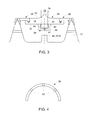
FIG. 3 is a side, cross-sectional view of a rotor cooling assembly having a first operable connection to the nozzle assembly; -
FIG. 4 is a cross-sectional view of a flow cooling dispenser taken along line IV-IV ofFIG. 3 ; -
FIG. 5 is a side, cross-sectional view of the rotor cooling assembly having a second operable connection to the nozzle assembly; and -
FIG. 6 is a side, cross-sectional view of the rotor cooling assembly having the flow splitter with a flat outer region. - The detailed description explains embodiments of the invention, together with advantages and features, by way of example with reference to the drawings.
- Referring to
FIGS. 1 and 2 , a steam turbine is generally referred to with thenumeral 10. The illustratedsteam turbine 10 is of a double flow configuration and includes anouter casing 12, aninner casing 14 and a plurality of nozzles and buckets forming plural stages on each of the axially spaced sides of thesteam turbine 10. Theturbine 10 also includes arotor 16 mounted to the buckets. Therotor 16 extends through opposite axial ends of thesteam turbine 10 and within aflow splitter 18 that is annularly configured, which may also be referred to as a tub. Theflow splitter 18 is located centrally of thesteam turbine 10 and receives steam through asteam inlet 20 for flow to the various turbine stages on the axially opposite sides of theflow splitter 18. Specifically, theflow splitter 18 includes opposite halves, which are typically mirror images of each other, and therefore only one half is illustrated and described. The opposite halves are referred to as atop half 22 and a bottom half (not shown), which are each of a semi-circular geometry. Thetop half 22 is disposed radially outward of therotor 16, which extends axially through thesteam turbine 10. - Referring now to
FIG. 3 , a cross-sectional view of arotor cooling assembly 24 is illustrated. Therotor cooling assembly 24 comprises the previously describedflow splitter 18 and acooling flow dispenser 26. Theflow splitter 18 extends circumferentially around therotor 16 and awheel 17 and is operably coupled to at least onenozzle assembly 28 via one or more fasteners or bonding agents. Alternatively, a hook configuration or other mechanical fasteners may be employed, as described below. Thewheel 17 is disposed between therotor 16 and a turbine bucket and is also cooled by therotor cooling assembly 24. Theflow splitter 18 includes aninner radius 30 and anouter surface 32 that forms aridge 34 that is centrally located on theouter surface 32, with respect to the axial direction of thesteam turbine 10. Theridge 34 biases incoming steam flow in multiple directions, as described above. Theflow splitter 18 includes a hollowedcore 36 for receiving acooling flow conduit 38. Thecooling flow conduit 38 is configured to transfer a cooling substance. The cooling substance may be comprised of various substances, provided the cooling substance is of a sufficiently low temperature to achieve the intended rotor cooling function to a sufficient degree. - The
cooling flow dispenser 26 extends circumferentially around therotor 16 and is operably coupled to theinner radius 30 of theflow splitter 18. The coupling between thecooling flow dispenser 26 and theflow splitter 18 may be facilitated via welding, for example, but it is to be appreciated that various other mechanical or chemical fastening approaches may be taken to provide the operable coupling. Agap 40 is present between at least a portion of thecooling flow dispenser 26 and theinner radius 30 of theflow splitter 18. Thegap 40 is configured to receive the cooling substance from thecooling flow conduit 38. Thecooling flow dispenser 26 includes at least onefirst aperture 42 extending radially inward toward therotor 16 and in afirst plane 44. Thefirst plane 44 is defined by loci of points and axes located in a single axial location of thesteam turbine 10. In other words, the at least onefirst aperture 42 directs the cooling substance radially inward toward therotor 16 to provide a cooling effect. Additionally, thecooling flow dispenser 26 includes at least onesecond aperture 46 extending radially inward, but also at an angle from the at least onefirst aperture 42, and therefore at an angle from thefirst plane 44. Specifically, the at least onesecond aperture 46 is configured to direct the cooling substance radially inward toward therotor 16, but also toward locations upstream or downstream of thesteam turbine 10. The precise angle that the at least onesecond aperture 46 is disposed from thefirst plane 44 may vary, but in one contemplated embodiment the angle may be about 30 degrees from thefirst plane 44 in either the upstream or downstream direction. It is also to be understood that either or both of the at least onefirst aperture 42 and the at least onesecond aperture 46 may comprise a plurality of apertures. In the case of the at least onefirst aperture 42, there may be a plurality of apertures spaced circumferentially from one another and all directed radially inward toward therotor 16 and within the first plane 44 (FIG. 4 ). As for the at least onesecond aperture 46, there may be a plurality of apertures on either axial side of the at least onefirst aperture 42, and disposed at an angle therefrom, and may also comprise a plurality of apertures extending circumferentially from one another around thecooling flow dispenser 26. It is to be appreciated that one or all of the at least onefirst aperture 42 and/or all or one of the at least onesecond aperture 46 may be tapered to improve the degree of pre-swirl imposed on the cooling substance as it passes through the apertures. Although the alignments of the at least onefirst aperture 42 and the at least onesecond aperture 46 are described above, it is to be understood that the at least onefirst aperture 42 may be disposed at an angle, either alone or in combination with the at least onesecond aperture 46. - In operation, the cooling substance travels through the
cooling flow conduit 38 and is expelled in thegap 40 defined between at least a portion of thecooling flow dispenser 26 and theinner radius 30 of theflow splitter 18. Further direction of the cooling substance is facilitated through the at least onefirst aperture 42 and the at least onesecond aperture 46. The at least onefirst aperture 42 directs the cooling substance radially inward within thefirst plane 44 and toward therotor 16 for a cooling effect. The at least onesecond aperture 46 directs the cooling substance radially inward, but at an angle to induce a pre-whirl of the cooling substance, thereby reducing friction with therotor 16 and windage interaction with therotor 16. - Referring now to
FIG. 5 , therotor cooling assembly 24 is illustrated and is similar in construction to that illustrated inFIG. 3 , however, includes an alternative attachment structure between theflow splitter 18 and the at least onenozzle assembly 28. In the illustrated embodiment, at least one hookjoint assembly 50 facilitates an operable connection between theflow splitter 18 and the at least onenozzle assembly 28. The at least one hookjoint assembly 50 includes ahook component 52 and a receivingcomponent 54. - Referring now to
FIG. 6 , therotor cooling assembly 24 is illustrated and is similar in construction to that illustrated inFIG. 3 , however, theflow splitter 18 includes a relatively flat surface 60 that defines theouter surface 32. This is in contrast to theflow splitter 18 that includes aridge 34 for splitting incoming flow. - Advantageously, the cooling
flow dispenser 26 provides the required cooling of therotor 16 and reduces windage with therotor 16 and reduces or eliminates excessive components that increase raw material cost and complicate the assembly process. - While the invention has been described in detail in connection with only a limited number of embodiments, it should be readily understood that the invention is not limited to such disclosed embodiments. Rather, the invention can be modified to incorporate any number of variations, alterations, substitutions or equivalent arrangements not heretofore described, but which are commensurate with the spirit and scope of the invention. Additionally, while various embodiments of the invention have been described, it is to be understood that aspects of the invention may include only some of the described embodiments. Accordingly, the invention is not to be seen as limited by the foregoing description, but is only limited by the scope of the appended claims.
- Various aspects and embodiments of the present invention are defined by the following numbered clauses:
- 1. A rotor and wheel cooling assembly for a steam turbine system comprising:
- a rotor operably connected to a plurality of rotating buckets;
- a flow diverting member having an inner radius and operably coupled to at least one nozzle stage, wherein the flow diverting member directs flow in at least one direction within the steam turbine system; and
- a cooling flow dispenser disposed radially outwardly of a portion of the rotor and having at least one aperture, wherein the cooling flow dispenser is operably coupled to the inner radius of the flow diverting member.
- 2. The rotor and wheel cooling assembly of clause 1, further comprising a cooling flow conduit for transferring a cooling substance.
- 3. The rotor and wheel cooling assembly of any preceding clause, wherein the cooling flow dispenser is circular and includes an outer radius.
- 4. The rotor and wheel cooling assembly of any preceding clause, further comprising a gap defined by the outer radius of the cooling flow dispenser and the inner radius of the flow diverting member.
- 5. The rotor and wheel cooling assembly of any preceding clause, wherein the gap receives the cooling substance.
- 6. The rotor and wheel cooling assembly of any preceding clause, further comprising a first plurality of apertures circumferentially arranged in the cooling flow dispenser, wherein the first plurality of apertures are angled radially inward toward the rotor in a first plane.
- 7. The rotor and wheel cooling assembly of any preceding clause, further comprising at least one angled aperture disposed at an angle from the first plane.
- 8. The rotor and wheel cooling assembly of any preceding clause, wherein the angle is about 30 degrees.
- 9. The rotor and wheel cooling assembly of any preceding clause, further comprising a second plurality of apertures, each of the second plurality of apertures disposed at an angle from the first plane.
- 10. The rotor and wheel cooling assembly of any preceding clause, wherein the cooling flow dispenser comprises a first semi-circle for circumferentially surrounding a first half of the rotor.
- 11. The rotor and wheel cooling assembly of any preceding clause, further comprising a second semi-circle for circumferentially surrounding a second half of the rotor.
- 12. A rotor and wheel cooling assembly for a steam turbine system comprising:
- a rotor operably connected to a plurality of rotating buckets;
- a cooling flow conduit for transferring a cooling substance;
- a flow diverting member having an inner radius, wherein the flow diverting member includes a ridge for directing flow in at least one direction within the steam turbine system;
- a cooling flow dispenser disposed radially outward of a portion of the rotor and having at least one aperture, wherein the cooling flow dispenser is operably coupled to the inner radius of the flow diverting member; and
- a gap disposed between the inner radius of the flow diverting member and the cooling flow dispenser for receiving the cooling substance from the cooling flow conduit.
- 13. The rotor and wheel cooling assembly of any preceding clause, further comprising a plurality of apertures circumferentially arranged in the cooling flow dispenser, wherein the plurality of apertures are angled radially inward toward the rotor in a first plane.
- 14. The rotor and wheel cooling assembly of any preceding clause, further comprising at least one angled aperture disposed at an angle from the first plane.
- 15. The rotor and wheel cooling assembly of any preceding clause, wherein the angle is about 30 degrees.
- 16. The rotor and wheel cooling assembly of any preceding clause, further comprising a second plurality of apertures, each of the second plurality of apertures disposed at an angle from the first plane.
- 17. The rotor and wheel cooling assembly of any preceding clause, wherein the cooling flow dispenser comprises a first semi-circle for circumferentially surrounding a first half of the rotor.
- 18. The rotor and wheel cooling assembly of any preceding clause, further comprising a second semi-circle for circumferentially surrounding a second half of the rotor.
- 19. A rotor and wheel cooling assembly for a steam turbine system comprising:
- a rotor operably connected to a plurality of rotating buckets;
- a wheel disposed between the rotor and a turbine bucket;
- a cooling flow conduit for transferring a cooling substance;
- a flow diverting member having an inner radius and fixedly connected with at least one nozzle stage by at least one hook assembly;
- a cooling flow dispenser disposed radially outward of a portion of the rotor and having a plurality of apertures, wherein the cooling flow dispenser is operably coupled to the inner radius of the flow diverting member; and
- a gap disposed between the inner radius of the flow diverting member and the cooling flow dispenser for receiving the cooling substance from the cooling flow conduit.
- 20. The rotor and wheel cooling assembly of any preceding clause, wherein a first aperture of the plurality of apertures is directed radially inward toward the rotor along a plane, and wherein a second aperture of the plurality of apertures is disposed at an angle to the plane.
Claims (15)
- A rotor (16) and wheel (17) cooling assembly for a steam turbine system (10) comprising:a rotor (16) operably connected to a plurality of rotating buckets;a flow diverting member (18) having an inner radius (30) and operably coupled to at least one nozzle stage (28), wherein the flow diverting member (18) directs flow in at least one direction within the steam turbine system(10); anda cooling flow dispenser (26) disposed radially outwardly of a portion of the rotor (16) and having at least one aperture (42), wherein the cooling flow dispenser (26) is operably coupled to the inner radius (30) of the flow diverting member (18).
- The rotor (16) and wheel (17) cooling assembly of claim 1, further comprising a cooling flow conduit (38) for transferring a cooling substance.
- The rotor (16) and wheel (17) cooling assembly of any preceding claim, wherein the cooling flow dispenser (26) is circular and includes an outer radius.
- The rotor (16) and wheel (17) cooling assembly of any preceding claim, further comprising a gap (40) defined by the outer radius (30) of the cooling flow dispenser (26) and the inner radius of the flow diverting member (18).
- The rotor (16) and wheel (17) cooling assembly of claim 4, wherein the gap (40) receives the cooling substance.
- The rotor (16) and wheel (17) cooling assembly of any preceding claim, further comprising a first plurality of apertures (42,46) circumferentially arranged in the cooling flow dispenser (26), wherein the first plurality of apertures (42,46) are angled radially inward toward the rotor in a first plane (44).
- The rotor (16) and wheel (17) cooling assembly of any preceding claim, further comprising at least one angled aperture disposed at an angle from the first plane (44).
- The rotor (16) and wheel (17) cooling assembly of claim 7, wherein the angle is about 30 degrees.
- The rotor (16) and wheel (17) cooling assembly of any preceding claim, further comprising a second plurality of apertures, each of the second plurality of apertures disposed at an angle from the first plane.
- The rotor (16) and wheel (17) cooling assembly of any preceding claim, wherein the cooling flow dispenser (26) comprises a first semi-circle for circumferentially surrounding a first half of the rotor.
- The rotor (16) and wheel (17) cooling assembly of claim 10, further comprising a second semi-circle for circumferentially surrounding a second half of the rotor (16).
- A rotor (16) and wheel (17) cooling assembly for a steam turbine system comprising:a rotor (16) operably connected to a plurality of rotating buckets;a cooling flow conduit for transferring a cooling substance;a flow diverting member (18) having an inner radius, wherein the flow diverting member includes a ridge for directing flow in at least one direction within the steam turbine system;a cooling flow dispenser (26) disposed radially outward of a portion of the rotor and having at least one aperture, wherein the cooling flow dispenser is operably coupled to the inner radius of the flow diverting member; anda gap (40) disposed between the inner radius of the flow diverting member and the cooling flow dispenser for receiving the cooling substance from the cooling flow conduit.
- The rotor (16) and wheel (17) cooling assembly of claim 12, further comprising a plurality of apertures circumferentially arranged in the cooling flow dispenser, wherein the plurality of apertures are angled radially inward toward the rotor in a first plane.
- The rotor (16) and wheel (17) cooling assembly of claim 13, further comprising at least one angled aperture disposed at an angle from the first plane.
- The rotor (16) and wheel (17) cooling assembly of claim 14, wherein the angle is about 30 degrees.
Applications Claiming Priority (1)
| Application Number | Priority Date | Filing Date | Title |
|---|---|---|---|
| US13/433,755 US20130259662A1 (en) | 2012-03-29 | 2012-03-29 | Rotor and wheel cooling assembly for a steam turbine system |
Publications (1)
| Publication Number | Publication Date |
|---|---|
| EP2644842A2 true EP2644842A2 (en) | 2013-10-02 |
Family
ID=48013797
Family Applications (1)
| Application Number | Title | Priority Date | Filing Date |
|---|---|---|---|
| EP13161177.4A Withdrawn EP2644842A2 (en) | 2012-03-29 | 2013-03-26 | Rotor and wheel cooling assembly for a steam turbine system |
Country Status (5)
| Country | Link |
|---|---|
| US (1) | US20130259662A1 (en) |
| EP (1) | EP2644842A2 (en) |
| JP (1) | JP2013204594A (en) |
| CN (1) | CN103362571A (en) |
| RU (1) | RU2013113934A (en) |
Family Cites Families (4)
| Publication number | Priority date | Publication date | Assignee | Title |
|---|---|---|---|---|
| CN1106496C (en) * | 1996-06-21 | 2003-04-23 | 西门子公司 | Turbine shaft and its cooling method |
| JP4509664B2 (en) * | 2003-07-30 | 2010-07-21 | 株式会社東芝 | Steam turbine power generation equipment |
| US7322789B2 (en) * | 2005-11-07 | 2008-01-29 | General Electric Company | Methods and apparatus for channeling steam flow to turbines |
| US8257015B2 (en) * | 2008-02-14 | 2012-09-04 | General Electric Company | Apparatus for cooling rotary components within a steam turbine |
-
2012
- 2012-03-29 US US13/433,755 patent/US20130259662A1/en not_active Abandoned
-
2013
- 2013-03-26 JP JP2013063185A patent/JP2013204594A/en active Pending
- 2013-03-26 EP EP13161177.4A patent/EP2644842A2/en not_active Withdrawn
- 2013-03-28 RU RU2013113934/06A patent/RU2013113934A/en not_active Application Discontinuation
- 2013-03-28 CN CN2013101030955A patent/CN103362571A/en active Pending
Non-Patent Citations (1)
| Title |
|---|
| None |
Also Published As
| Publication number | Publication date |
|---|---|
| US20130259662A1 (en) | 2013-10-03 |
| JP2013204594A (en) | 2013-10-07 |
| RU2013113934A (en) | 2014-10-10 |
| CN103362571A (en) | 2013-10-23 |
Similar Documents
| Publication | Publication Date | Title |
|---|---|---|
| US10746048B2 (en) | Annular ring assembly for shroud cooling | |
| US9309783B2 (en) | Seal assembly for turbine system | |
| US9810081B2 (en) | Cooled conduit for conveying combustion gases | |
| US10662815B2 (en) | Integrated strut and turbine vane nozzle arrangement | |
| US8348608B2 (en) | Turbomachine rotor cooling | |
| US8807927B2 (en) | Clearance flow control assembly having rail member | |
| US20150013345A1 (en) | Gas turbine shroud cooling | |
| US10422249B2 (en) | Exhaust frame | |
| JP6386716B2 (en) | Articulated transition duct in turbomachinery | |
| JP2012112379A (en) | Turbomachine nozzle segment having integrated diaphragm | |
| US8628297B2 (en) | Tip flowpath contour | |
| KR102323262B1 (en) | Steam turbine and methods of assembling the same | |
| EP2644842A2 (en) | Rotor and wheel cooling assembly for a steam turbine system | |
| JP2009191850A (en) | Steam turbine engine and assembly method thereof | |
| JP2017538062A (en) | Compressor bleed passage having an auxiliary impeller in the axial bore | |
| EP3265653B1 (en) | Turbine for organic rankine cycles with axial input and output | |
| EP2716864B1 (en) | Turbine tip leakage reduction system | |
| EP2653663A2 (en) | Seal for a turbine system | |
| WO2015069125A1 (en) | Turbomachine exhaust frame | |
| JP6259189B2 (en) | Blade with tip shroud | |
| US20170226862A1 (en) | Fluid cooled rotor for a gas turbine | |
| US20140119886A1 (en) | Turbine cowling system | |
| CN104373215A (en) | Inner barrel member with integrated diffuser for a gas turbomachine | |
| JP2015528878A (en) | Turbine shroud for turbomachine | |
| US20180023404A1 (en) | Ring segment system for gas turbine engines |
Legal Events
| Date | Code | Title | Description |
|---|---|---|---|
| PUAI | Public reference made under article 153(3) epc to a published international application that has entered the european phase |
Free format text: ORIGINAL CODE: 0009012 |
|
| AK | Designated contracting states |
Kind code of ref document: A2 Designated state(s): AL AT BE BG CH CY CZ DE DK EE ES FI FR GB GR HR HU IE IS IT LI LT LU LV MC MK MT NL NO PL PT RO RS SE SI SK SM TR |
|
| AX | Request for extension of the european patent |
Extension state: BA ME |
|
| STAA | Information on the status of an ep patent application or granted ep patent |
Free format text: STATUS: THE APPLICATION IS DEEMED TO BE WITHDRAWN |
|
| 18D | Application deemed to be withdrawn |
Effective date: 20151001 |