EP2644352A2 - Injection molding machine with two cylinders - Google Patents
Injection molding machine with two cylinders Download PDFInfo
- Publication number
- EP2644352A2 EP2644352A2 EP13156947.7A EP13156947A EP2644352A2 EP 2644352 A2 EP2644352 A2 EP 2644352A2 EP 13156947 A EP13156947 A EP 13156947A EP 2644352 A2 EP2644352 A2 EP 2644352A2
- Authority
- EP
- European Patent Office
- Prior art keywords
- drive member
- cylinder
- recommended value
- injection molding
- synchronization
- Prior art date
- Legal status (The legal status is an assumption and is not a legal conclusion. Google has not performed a legal analysis and makes no representation as to the accuracy of the status listed.)
- Granted
Links
Images


Classifications
-
- B—PERFORMING OPERATIONS; TRANSPORTING
- B29—WORKING OF PLASTICS; WORKING OF SUBSTANCES IN A PLASTIC STATE IN GENERAL
- B29C—SHAPING OR JOINING OF PLASTICS; SHAPING OF MATERIAL IN A PLASTIC STATE, NOT OTHERWISE PROVIDED FOR; AFTER-TREATMENT OF THE SHAPED PRODUCTS, e.g. REPAIRING
- B29C45/00—Injection moulding, i.e. forcing the required volume of moulding material through a nozzle into a closed mould; Apparatus therefor
- B29C45/17—Component parts, details or accessories; Auxiliary operations
- B29C45/18—Feeding the material into the injection moulding apparatus, i.e. feeding the non-plastified material into the injection unit
-
- B—PERFORMING OPERATIONS; TRANSPORTING
- B29—WORKING OF PLASTICS; WORKING OF SUBSTANCES IN A PLASTIC STATE IN GENERAL
- B29C—SHAPING OR JOINING OF PLASTICS; SHAPING OF MATERIAL IN A PLASTIC STATE, NOT OTHERWISE PROVIDED FOR; AFTER-TREATMENT OF THE SHAPED PRODUCTS, e.g. REPAIRING
- B29C45/00—Injection moulding, i.e. forcing the required volume of moulding material through a nozzle into a closed mould; Apparatus therefor
- B29C45/17—Component parts, details or accessories; Auxiliary operations
-
- B—PERFORMING OPERATIONS; TRANSPORTING
- B29—WORKING OF PLASTICS; WORKING OF SUBSTANCES IN A PLASTIC STATE IN GENERAL
- B29C—SHAPING OR JOINING OF PLASTICS; SHAPING OF MATERIAL IN A PLASTIC STATE, NOT OTHERWISE PROVIDED FOR; AFTER-TREATMENT OF THE SHAPED PRODUCTS, e.g. REPAIRING
- B29C45/00—Injection moulding, i.e. forcing the required volume of moulding material through a nozzle into a closed mould; Apparatus therefor
- B29C45/17—Component parts, details or accessories; Auxiliary operations
- B29C45/76—Measuring, controlling or regulating
-
- B—PERFORMING OPERATIONS; TRANSPORTING
- B29—WORKING OF PLASTICS; WORKING OF SUBSTANCES IN A PLASTIC STATE IN GENERAL
- B29C—SHAPING OR JOINING OF PLASTICS; SHAPING OF MATERIAL IN A PLASTIC STATE, NOT OTHERWISE PROVIDED FOR; AFTER-TREATMENT OF THE SHAPED PRODUCTS, e.g. REPAIRING
- B29C45/00—Injection moulding, i.e. forcing the required volume of moulding material through a nozzle into a closed mould; Apparatus therefor
- B29C45/17—Component parts, details or accessories; Auxiliary operations
- B29C45/76—Measuring, controlling or regulating
- B29C45/77—Measuring, controlling or regulating of velocity or pressure of moulding material
-
- B—PERFORMING OPERATIONS; TRANSPORTING
- B29—WORKING OF PLASTICS; WORKING OF SUBSTANCES IN A PLASTIC STATE IN GENERAL
- B29C—SHAPING OR JOINING OF PLASTICS; SHAPING OF MATERIAL IN A PLASTIC STATE, NOT OTHERWISE PROVIDED FOR; AFTER-TREATMENT OF THE SHAPED PRODUCTS, e.g. REPAIRING
- B29C2945/00—Indexing scheme relating to injection moulding, i.e. forcing the required volume of moulding material through a nozzle into a closed mould
- B29C2945/76—Measuring, controlling or regulating
- B29C2945/76003—Measured parameter
- B29C2945/7611—Velocity
- B29C2945/7612—Velocity rotational movement
-
- B—PERFORMING OPERATIONS; TRANSPORTING
- B29—WORKING OF PLASTICS; WORKING OF SUBSTANCES IN A PLASTIC STATE IN GENERAL
- B29C—SHAPING OR JOINING OF PLASTICS; SHAPING OF MATERIAL IN A PLASTIC STATE, NOT OTHERWISE PROVIDED FOR; AFTER-TREATMENT OF THE SHAPED PRODUCTS, e.g. REPAIRING
- B29C2945/00—Indexing scheme relating to injection moulding, i.e. forcing the required volume of moulding material through a nozzle into a closed mould
- B29C2945/76—Measuring, controlling or regulating
- B29C2945/76177—Location of measurement
- B29C2945/7618—Injection unit
- B29C2945/76187—Injection unit screw
-
- B—PERFORMING OPERATIONS; TRANSPORTING
- B29—WORKING OF PLASTICS; WORKING OF SUBSTANCES IN A PLASTIC STATE IN GENERAL
- B29C—SHAPING OR JOINING OF PLASTICS; SHAPING OF MATERIAL IN A PLASTIC STATE, NOT OTHERWISE PROVIDED FOR; AFTER-TREATMENT OF THE SHAPED PRODUCTS, e.g. REPAIRING
- B29C2945/00—Indexing scheme relating to injection moulding, i.e. forcing the required volume of moulding material through a nozzle into a closed mould
- B29C2945/76—Measuring, controlling or regulating
- B29C2945/76177—Location of measurement
- B29C2945/7618—Injection unit
- B29C2945/7619—Injection unit barrel
- B29C2945/76193—Injection unit barrel barrel-chamber
- B29C2945/76197—Injection unit barrel barrel-chamber screw ante-chamber
-
- B—PERFORMING OPERATIONS; TRANSPORTING
- B29—WORKING OF PLASTICS; WORKING OF SUBSTANCES IN A PLASTIC STATE IN GENERAL
- B29C—SHAPING OR JOINING OF PLASTICS; SHAPING OF MATERIAL IN A PLASTIC STATE, NOT OTHERWISE PROVIDED FOR; AFTER-TREATMENT OF THE SHAPED PRODUCTS, e.g. REPAIRING
- B29C2945/00—Indexing scheme relating to injection moulding, i.e. forcing the required volume of moulding material through a nozzle into a closed mould
- B29C2945/76—Measuring, controlling or regulating
- B29C2945/76344—Phase or stage of measurement
- B29C2945/76367—Metering
-
- B—PERFORMING OPERATIONS; TRANSPORTING
- B29—WORKING OF PLASTICS; WORKING OF SUBSTANCES IN A PLASTIC STATE IN GENERAL
- B29C—SHAPING OR JOINING OF PLASTICS; SHAPING OF MATERIAL IN A PLASTIC STATE, NOT OTHERWISE PROVIDED FOR; AFTER-TREATMENT OF THE SHAPED PRODUCTS, e.g. REPAIRING
- B29C2945/00—Indexing scheme relating to injection moulding, i.e. forcing the required volume of moulding material through a nozzle into a closed mould
- B29C2945/76—Measuring, controlling or regulating
- B29C2945/76822—Phase or stage of control
- B29C2945/76846—Metering
-
- B—PERFORMING OPERATIONS; TRANSPORTING
- B29—WORKING OF PLASTICS; WORKING OF SUBSTANCES IN A PLASTIC STATE IN GENERAL
- B29C—SHAPING OR JOINING OF PLASTICS; SHAPING OF MATERIAL IN A PLASTIC STATE, NOT OTHERWISE PROVIDED FOR; AFTER-TREATMENT OF THE SHAPED PRODUCTS, e.g. REPAIRING
- B29C2945/00—Indexing scheme relating to injection moulding, i.e. forcing the required volume of moulding material through a nozzle into a closed mould
- B29C2945/76—Measuring, controlling or regulating
- B29C2945/76929—Controlling method
- B29C2945/76933—The operating conditions are corrected immediately, during the same phase or cycle
-
- B—PERFORMING OPERATIONS; TRANSPORTING
- B29—WORKING OF PLASTICS; WORKING OF SUBSTANCES IN A PLASTIC STATE IN GENERAL
- B29C—SHAPING OR JOINING OF PLASTICS; SHAPING OF MATERIAL IN A PLASTIC STATE, NOT OTHERWISE PROVIDED FOR; AFTER-TREATMENT OF THE SHAPED PRODUCTS, e.g. REPAIRING
- B29C2945/00—Indexing scheme relating to injection moulding, i.e. forcing the required volume of moulding material through a nozzle into a closed mould
- B29C2945/76—Measuring, controlling or regulating
- B29C2945/76929—Controlling method
- B29C2945/76939—Using stored or historical data sets
- B29C2945/76943—Using stored or historical data sets compare with thresholds
Definitions
- the present invention relates to an injection molding machine that uses two cylinders to transport (meter) a molding material.
- Patent Document 1 Japanese Laid-Open Patent Publication No. 2009-90614
- One particular object of at least one embodiment of the present invention is to reduce the burden of a user during initial setting operations of the injection molding machine.
- an injection molding machine includes a first cylinder; a second cylinder that is connected to the first cylinder; a first drive member that is arranged at the first cylinder and is configured to move a molding material within the first cylinder toward the second cylinder; a second drive member that is arranged at the second cylinder and is configured to operate in sync with the first drive member and move the molding material supplied to the second cylinder from the first cylinder by the first drive member in a forward direction; and an information output apparatus that outputs a recommended value for a ratio of a first setting value to a second setting value, where the first setting value relates to an operational speed of the first drive member, and the second setting value relates to an operational speed of the second drive member.
- the burden on a user may be reduced during initial setting operations of the injection molding machine.
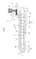
- FIG. 1 is a cross-sectional view of an exemplary injection device 31 that may be used in an injection molding machine according to an embodiment of the present invention.
- the injection molding machine according to the present embodiment includes a mold device (not shown), a clamping device (not shown), and the injection device 31.
- the mold device includes a first mold corresponding to a stationary mold and a second mold corresponding to a movable mold.
- the clamping device includes a stationary platen to which the stationary mold is attached, a movable platen to which the movable mold is attached, and a clamping cylinder that moves the movable platen forward and backward to close, clamp, and open the mold device.
- the clamping device may be an electromagnetic clamping device or a clamping device using a toggle mechanism, for example.
- the injection device includes a heating cylinder 17, an injection nozzle 18 that is arranged at the front end of the heating cylinder 17, a main screw 20 that is arranged inside the heating cylinder 17 in a manner such that the main screw 20 may rotate and move back and forth within the heating cylinder 17, heaters h11-h13 that are arranged at the outer periphery of the heating cylinder 17, and a drive unit 101 that is arranged at the rear end portion of the heating cylinder 17.
- the drive unit 101 includes an injection motor and a metering motor, for example.
- the main screw 20 includes a screw body 52, an injection part 46 that is arranged at the front end portion of the screw body 52, and an shaft part 51 that is arranged at the rear end portion of the screw body 52 and is connected to the drive unit 101.
- the screw body 52 includes a flight part 45 and a pressure member 54 that is detachably arranged at the front end portion of the flight part 45.
- the flight part 45 includes a rod-shaped body 45a and a spiral flight 53 protruding from the outer periphery of the body 45a.
- the flight 53 forms a spiral groove 67 around the outer periphery of the body 45a.
- the pressure member 54 may be omitted and the flight part 45 may extend substantially the entire length of the screw body 52.
- the injection part 46 includes a head part (screw head) 55 having a tip portion that is conically-shaped, a rod part 56 arranged adjacent to the head part 55 at the rear end portion of the head part 55, a check ring 57 arranged around the rod part 56, and a seal ring 58 that is attached to the front end portion of the pressure member 54.
- a head part screw head 55 having a tip portion that is conically-shaped, a rod part 56 arranged adjacent to the head part 55 at the rear end portion of the head part 55, a check ring 57 arranged around the rod part 56, and a seal ring 58 that is attached to the front end portion of the pressure member 54.
- a seal realized by a backflow prevention device 62 is released.
- the seal is realized by the backflow prevention device 62.
- a resin supply port 65 as a molding material supply port is arranged near the rear end of the heating cylinder 17.
- the resin supply port 65 is arranged to oppose a rear portion of the groove 67 when the main screw 20 is positioned at a maximum forward position within the heating cylinder 17.
- a loading unit 81 for loading resin is attached to the resin supply port 65.
- a hopper 82 for accommodating pelletized resin is arranged at an upper portion of the loading unit 81. The resin accommodated in the hopper 82 is transferred to the resin supply port 65 via the loading unit 81 and is supplied to the heating cylinder 17 from the resin supply port 65.
- the loading unit 81 includes a cylinder part 83 that is arranged to extend horizontally, a guide part 84 that is arrange to extend downward from the front portion of the cylinder part 83, a feed screw 85 that is arranged to be rotatable within the cylinder part 83, a feed motor 86 that rotates the feed screw 85, and a heater h21 that is arranged at the outer periphery of the cylinder part 83, for example.
- the rear portion of the cylinder part 83 is connected to the hopper 82 and the front portion of the cylinder part 83 is connected to the guide part 84.
- the resin within the hopper 82 is supplied to the interior of the cylinder part 83 and is moved forward along a groove formed on the outer periphery of the feed screw 85. During this time, the resin is heated by the heater h21 to be preheated. The resin is then transferred from the front portion of the feed screw 85 to the guide part 84 and is dropped through the guide part 84 to be supplied to the heating cylinder 17.
- the feed screw 85 and the main screw 20 are rotated in the forward direction.
- the resin within the hopper 82 is supplied to the cylinder part 83, is moved forward along the groove formed on the outer periphery of the feed screw 85 while being preheated by the heater h21, is transferred to the guide part 84 from the front portion of the feed screw 85, is dropped through the guide part 84, and is supplied to the heating cylinder 17.
- the resin within the cylinder part 83 is preheated to a predetermined temperature that would not cause melting of the resin.
- the resin within the cylinder part 83 may be preheated to a temperature below the glass-transition temperature.
- the resin supplied to the heating cylinder 17 is moved forward along the groove 67 and is heated to be melted by the heaters h11-h13. It is noted that the pressure of the resin within the heating cylinder 17 gradually increases as the resin is moved toward the front end portion of the screw body 52 from a pressure increase starting point at a predetermined distance away from the pressure member 54.
- the resin passes through the resin flow path between the heating cylinder 17 and the pressure member 54 during which time the pressure of the resin is increased further so that the resin may be adequately kneaded. Then, the resin passes through the resin flow path between the heating cylinder 17 and the rod part 56 and is moved forward to the front portion of the screw head 55. Also, in order to add back pressure to the main screw 20 during the metering process, the injection motor (not shown) of the drive unit 101 is driven to prevent the main screw 20 from moving backward.
- the main screw 20 is moved forward while being prevented from rotating by the drive unit 101.
- the resin transported to the front portion of the screw head 55 is injected from the injection nozzle 18 and filled into a cavity of the mold device.
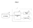
- FIG. 2 is a block diagram showing an exemplary configuration of an information output apparatus 1 that may be used in the injection molding machine according to the present embodiment.
- the information output apparatus 1 includes a processing unit 10 and a display unit 12.
- the information output apparatus 1 may optionally include an input unit 14 as well.
- the information output apparatus 1 is connected to a database 16. It is noted that in certain embodiments, the database 16 may be installed within the information output apparatus 1.
- the processing unit 10 may be realized by hardware, software, firmware, or a combination of at least two of the above.
- the processing unit 10 may include a CPU (central processing unit) that realizes one or more of the functions described below.
- the display unit 12 may be any type of display such as a liquid crystal display (LCD).
- the display unit 12 may provide a control screen for controlling the injection molding machine, for example.
- the display unit 12 is controlled by the processing unit 10 to display information such as a recommended value for the rate of synchronization between the feed screw 85 and the main screw 20. It is noted that a method of displaying such information is described below.
- the input unit 14 may be a user interface for the user of the injection molding machine.
- the input unit 14 may be any type of user interface such as a keyboard or a mouse.
- the display unit 12 may be a touch panel display and the input unit 14 may be a touch switch that is displayed on the touch panel display.
- the database 16 may be any type of storage device such as a HDD (hard disk drive).
- the database 16 may be connected to the information output apparatus 1 via a cable or a wireless connection.
- the database 16 may be a removable storage medium, and in such case, the storage medium may be inserted into a predetermined slot of the information output apparatus 1 upon use.
- the database 16 may be an external server. In such case, the information output apparatus 1 may access the database 16 via a network.
- the database 16 may be a predetermined memory installed within the information output apparatus 1.
- the predetermined memory may be a memory that cannot be rewritten such as a ROM (read-only memory) or a rewritable memory such as an EEPROM (electrically erasable programmable read-only memory).
- information stored in the database 16 may be updated periodically or on random occasions, for example.
- the database 16 stores information such as the recommended value for the rate of synchronization between the feed screw 85 and the main screw 20.
- FIG. 3 is a flowchart showing exemplary process steps for configuring the database 16 according to a first embodiment. It is noted that the process of FIG. 3 may be performed by the manufacturer of the injection molding machine, for example.
- step S300 a combination of the feed screw 85 and the main screw 20 that may be used in the injection molding machine is determined.
- the feed screw 85 may be selected from a number of different feed screws having different diameters, for example.
- the main screw 20 may be selected from a number of different main screws having different diameters, for example.
- a recommended value for the rate of synchronization is derived for the combination of the feed screw 85 and the main screw 20 determined in step S300.
- the rate of synchronization refers to the ratio of the rotation speed of the feed screw 85 to the rotation speed of the main screw 20; i.e., (feed screw 85 rotation speed)/(main screw 20 rotation speed).
- the recommended value for the rate of synchronization may be derived in any manner such as trial and error.
- the recommended value may be derived by actually operating the injection molding machine while changing the rate of synchronization to compare and verify various types of data.
- the recommended value is based on unique standards developed by each individual manufacture so that even when the same combination of the feed screw 85 and the main screw 20 is used, the corresponding recommended value for the rate of synchronization may vary depending on the manufacturer.
- step S304 a determination is made as to whether a recommended value for the rate of synchronization has been derived for every conceivable combination of the feed screw 85 and the main screw 20. If a recommended value for the rate of synchronization has not yet been derived for a given combination of the feed screw 85 and the main screw 20, the process goes back to step S300, and a recommended value for the rate of synchronization is derived for the given combination of the feed screw 85 and the main screw 20 in step S302. In this way, recommended values for the rate of synchronization are derived for all conceivable combinations of the feed screw 85 and the main screw 20.
- injection molding machines may only accommodate a specific combination of the feed screw 85 and the main screw 20 while other types of injection molding machines may accommodate plural different combinations of the feed screw 85 and the main screw 20.
- the present embodiment may be implemented in any type of injection molding machine so that a recommended value for the rate of synchronization may be derived for each conceivable combination of the feed screw 85 and the main screw 20.
- step S304 may be omitted.
- step S306 the recommended values for the rate of synchronization for the combinations of the feed screw 85 and the main screw 20 are stored in the database 16. It is noted that the recommended values are stored in association with the corresponding combination of the feed screw 85 and the main screw 20.
- a recommended value for the rate of synchronization for each combination of the feed screw 85 and the main screw 20 is stored in the database 16. It is noted that the process steps shown in FIG. 3 may be performed when a new combination of the feed screw 85 and the main screw 20 becomes available, for example. In such case, a recommended value for the rate of synchronization for the new combination of the feed screw 85 and the main screw 20 may be additionally stored in the database 16.
- FIG. 4 is a flowchart showing exemplary process steps for outputting a recommended value for the rate of synchronization according to the first embodiment. It is noted that the process steps shown in FIG. 4 is performed by the information outputting apparatus 1. The process steps of FIG. 4 may be performed at a time an output of a recommended value for the rate of synchronization is needed. For example, the process steps of FIG. 4 may be performed upon starting operations for initially setting up (or adjusting) the rotation speeds of the feed screw 85 and the main screw 20 (e.g., when a corresponding command is input by the user via the input unit 14).
- step S400 the combination of the feed screw 85 and the main screw 20 that is used in the injection molding machine including the information output apparatus 1 is determined.
- the combination of the feed screw 85 and the main screw 20 may be determined based on data input by the user or data that is preregistered by the manufacturer, for example.
- step S402 the corresponding recommended value for the rate of synchronization for the combination of the feed screw 85 and the main screw 20 determined in step S400 is extracted from the database 16.
- the database 16 may be an external database, an external memory, or a memory installed in the information output apparatus 1.
- the database 16 may store the recommended value for the rate of synchronization for this one combination.
- the processing unit 10 may obtain the recommended value by simply reading the recommended value for the rate of synchronization stored in the database 16.
- step S404 the recommended value for the rate of synchronization extracted in step S402 is output to the display unit 12.
- the recommended value for the rate of synchronization may be output in any manner.
- an explanation (definition) of the rate of synchronization may also be displayed.
- the recommended value for the rate of synchronization may be output as sound in addition to or in place of outputting a display of the recommended value.
- the user may be informed of the recommended value for the rate of synchronization for the combination of the feed screw 85 and the main screw 20 used in the injection molding machine. Accordingly, the user may adjust the rotation speed of the feed screw 85 and the rotation speed of the main screw 20 based on the recommended value for the rate of synchronization. In this way, the user of the injection molding machine may perform initial setting operations and other operations for setting up or adjusting the rotation speeds of the feed screw 85 and the main screw 20 more efficiently, for example.
- the recommended value for the rate of synchronization is output.
- a recommended range (recommended variable range) for the rate of synchronization may be output in addition to the recommended value for the rate of synchronization.
- the recommended variable range for the rate of synchronization may be derived beforehand at the manufacturer side in a manner similar to deriving the recommended value for the rate of synchronization (see FIG. 3 ) and the derived range may be stored in the database 16.
- the recommended variable range may be represented by an upper limit and a lower limit of the rate of synchronization, for example.
- the recommended variable range for the rate of synchronization may be displayed in combination with the recommended value for the rate of synchronization. For example, the recommended value for the rate of synchronization may be indicated within a display of the recommended variable range for the rate of synchronization.
- step S402 of FIG. 4 when a recommended value for the rate of synchronization corresponding to the combination of the feed screw 85 and the main screw 20 determined in step S400 is not stored in the database 16, the corresponding recommended value for the rate of synchronization for this combination may be calculated and derived based on a recommended value for the rate of synchronization for another combination (a recommended value for the rate of synchronization that is stored in the database 16).
- a predetermined conversion formula or interpolation formula
- FIG. 5 is a flowchart showing exemplary process steps for configuring the database 16 according to a second embodiment of the present invention. It is noted that the process steps of FIG. 5 may be performed by the manufacturer of the injection molding machine, for example.
- step S500 the resin (molding material) that may be used in the injection molding machine is determined.
- a recommended value for the rate of synchronization is derived for the resin determined in step S500. It is noted that the recommended value is derived based on unique standards developed by each individual manufacturer so that the recommended value for the same resin may vary depending on the manufacturer.
- step S504 a determination is made as to whether a recommended value for the rate of synchronization has been derived for each resin that may be used in the injection molding machine. If a recommended value for the rate of synchronization has not yet been derived for a given resin that may be used in the injection molding machine, the process goes back to step S500, and a recommended value for the rate of synchronization is derived for the given resin in step S502. In this way, recommended values for the rate of synchronization are derived for all resins that may be used in the injection molding machine. It is noted that the resins for which the recommended values for the synchronized rate are derived may be resins of different types, for example.
- the resins for which the recommended values are derived may be resins with or without some other material (e.g., fiberglass) mixed thereto or resins having a material mixed thereto at different ratios, for example. Also, the resins for which the recommended values are derived may be distinguished based on whether they are new or recycled, whether they have recycled material mixed thereto, or the ratio at which the recycled material is mixed thereto, for example.
- step S506 the recommended values for the different resins are stored in the database 16. It is noted that the recommended values may be stored in association with their corresponding resin.
- recommended values for the rate of synchronization for different resins that may be used in the injection molding machine may be stored in the database 16. It is noted that the process steps shown in FIG. 5 may be performed when a new resin becomes available for use in the injection molding machine, for example. In such case, a recommended value for the rate of synchronization for the new resin may be additionally stored in the database 16.
- FIG. 6 is a flowchart showing exemplary process steps for outputting the recommended value for the rate of synchronization according to the second embodiment. It is noted that the process steps of FIG. 6 is performed by the information output apparatus 1. The process steps of FIG. 6 may be performed at a time an output of a recommended value for the rate of synchronization is needed. For example, the process steps of FIG. 6 may be performed upon starting operations for initially setting up (or adjusting) the rotation speeds of the feed screw 85 and the main screw 20 (e.g., when a corresponding command is input by the user via the input unit 14).
- step S600 the resin that is used in the injection molding machine including the information output apparatus 1 is determined.
- the resin used in the injection molding machine may be determined based on some form of resin input information.
- the resin used in the injection molding machine may be determined based on data input by the user (corresponding to one example of resin input information) or data that is preregistered by the manufacturer (corresponding to another example of resin input information).
- step S602 the corresponding recommended value for the rate of synchronization for the resin determined in step S600 is extracted from the database 16.
- the database 16 may be an external database, an external memory, or a memory installed in the information output apparatus 1.
- the database 16 may store the recommended value for the rate of synchronization for this resin.
- the processing unit 10 may obtain the recommended value by simply reading the recommended value for the rate of synchronization stored in the database 16.
- step S604 the recommended value for the rate of synchronization extracted in step S602 is output to the display unit 12.
- the recommended value for the rate of synchronization may be output in any manner.
- an explanation (definition) of the rate of synchronization may also be displayed.
- the recommended value for the rate of synchronization may be output as sound in addition to or in place of outputting a display of the recommended value.
- the user may be informed of the recommended value for the rate of synchronization for the resin used in the injection molding machine. For example, when the user selects the resin being used via a setting screen, the recommended value for the rate of synchronization corresponding to the selected resin may be output. Accordingly, the user may adjust the rotation speed of the feed screw 85 and the rotation speed of the main screw 20 based on the output recommended value for the rate of synchronization. In this way, the user of the injection molding machine may perform initial setting operations and other operations for setting up or adjusting the rotation speeds of the feed screw 85 and the main screw 20 more efficiently, for example.
- the recommended value for the rate of synchronization is output.
- a recommended range (recommended variable range) for the rate of synchronization may be output in addition to the recommended value for the rate of synchronization.
- the recommended variable range for the rate of synchronization may be derived beforehand at the manufacturer side in a manner similar to deriving the recommended value for the rate of synchronization (see FIG. 5 ) and the derived range may be stored in association with the corresponding resin in the database 16.
- the recommended variable range may be represented by an upper limit and a lower limit of the rate of synchronization, for example.
- the recommended variable range for the rate of synchronization may be displayed in combination with the recommended value for the rate of synchronization. For example, the recommended value for the rate of synchronization may be indicated within a display of the recommended variable range for the rate of synchronization.
- the process steps of FIGS. 5 and 6 according to the second embodiment may be used in combination with the process steps of FIGS. 3 and 4 according to the first embodiment. That is, a recommended value for the rate of synchronization may be stored in the database 16 in association with a corresponding combination of the feed screw 85 and the main screw 20 and a corresponding resin. In such case, the process steps of FIGS. 5 and 6 may be performed with respect to each conceivable combination of the feed screw 85 and the main screw 20, for example. In this way, a recommended value for the rate of synchronization corresponding to the combination of the feed screw 85 and the main screw 20 being used and the resin being used may be output.
- the "cylinder part 83" described above corresponds to an exemplary embodiment of the "first cylinder” of the present invention
- the "heating cylinder 17” described above corresponds to an exemplary embodiment of the “second cylinder” of the present invention
- the "feed screw 85” described above corresponds to an exemplary embodiment of the "first drive member” of the present invention
- the "main screw 20" described above corresponds to an exemplary embodiment of the "second drive member” of the present invention.
- a recommended value for the rate of synchronization is output in the embodiments described above, in other embodiments, a recommended value for a substantive equivalent of the above rate of synchronization may be output.
- a recommended value for the ratio of the rotation speed of the main screw 20 to the rotation speed of the feed screw 85 may be output.
- a recommended value for the ratio of the applied current or applied voltage of the motor driving the main screw 20 to the applied current or applied voltage of the motor driving the feed screw 85, or a recommended value for the ratio of the molding material transporting capacity of the main screw 20 to the molding material supply capacity of the feed screw 85 may be output.
Landscapes
- Engineering & Computer Science (AREA)
- Manufacturing & Machinery (AREA)
- Mechanical Engineering (AREA)
- Injection Moulding Of Plastics Or The Like (AREA)
Abstract
Description
- The present invention relates to an injection molding machine that uses two cylinders to transport (meter) a molding material.
- Conventional injection molding machines of the above type are known. (See, e.g., Patent Document 1) [Patent Document 1] Japanese Laid-Open Patent Publication No.
2009-90614 - It is noted that in the injection molding machine of the above type, two screws (drive members) arranged within the two cylinders operate in sync to transport (meter) the molding material. However, setting up the operational speed of the drive members to a suitable speed requires trial and error so that initial setting operations may be quite burdensome for the user of the injection molding machine.
- It is a general object of at least one embodiment of the present invention to provide an injection molding machine that substantially obviates one or more problems caused by the limitations and disadvantages of the related art. One particular object of at least one embodiment of the present invention is to reduce the burden of a user during initial setting operations of the injection molding machine.
- In one embodiment of the present invention, an injection molding machine includes a first cylinder; a second cylinder that is connected to the first cylinder; a first drive member that is arranged at the first cylinder and is configured to move a molding material within the first cylinder toward the second cylinder; a second drive member that is arranged at the second cylinder and is configured to operate in sync with the first drive member and move the molding material supplied to the second cylinder from the first cylinder by the first drive member in a forward direction; and an information output apparatus that outputs a recommended value for a ratio of a first setting value to a second setting value, where the first setting value relates to an operational speed of the first drive member, and the second setting value relates to an operational speed of the second drive member.
- According to an aspect of the present invention, the burden on a user may be reduced during initial setting operations of the injection molding machine.
- Other objects, features and advantages of the present invention will become more apparent from the following detailed description when read in conjunction with the accompanying drawings, in which:
-
FIG. 1 is a cross-sectional view of an exemplary injection device that may be used in an injection molding machine according to an embodiment of the present invention; -
FIG. 2 is a block diagram showing an exemplary configuration of an information output apparatus that may be used in the injection molding machined; -
FIG. 3 is a flowchart showing exemplary process steps for configuring a database according to a first embodiment of the present invention; -
FIG. 4 is a flowchart showing exemplary process steps for outputting a recommended value for a rate of synchronization according to the first embodiment; -
FIG. 5 is a flowchart showing exemplary process steps for configuring the database according to a second embodiment of the present invention; and -
FIG. 6 is a flowchart showing exemplary process steps for outputting the recommended value for the rate of synchronization according to the second embodiment. - In the following, embodiments of the present invention are described with reference to the accompanying drawings.
-
FIG. 1 is a cross-sectional view of anexemplary injection device 31 that may be used in an injection molding machine according to an embodiment of the present invention. The injection molding machine according to the present embodiment includes a mold device (not shown), a clamping device (not shown), and theinjection device 31. The mold device includes a first mold corresponding to a stationary mold and a second mold corresponding to a movable mold. The clamping device includes a stationary platen to which the stationary mold is attached, a movable platen to which the movable mold is attached, and a clamping cylinder that moves the movable platen forward and backward to close, clamp, and open the mold device. It is noted that the clamping device may be an electromagnetic clamping device or a clamping device using a toggle mechanism, for example. - The injection device includes a
heating cylinder 17, aninjection nozzle 18 that is arranged at the front end of theheating cylinder 17, amain screw 20 that is arranged inside theheating cylinder 17 in a manner such that themain screw 20 may rotate and move back and forth within theheating cylinder 17, heaters h11-h13 that are arranged at the outer periphery of theheating cylinder 17, and adrive unit 101 that is arranged at the rear end portion of theheating cylinder 17. Thedrive unit 101 includes an injection motor and a metering motor, for example. - The
main screw 20 includes ascrew body 52, aninjection part 46 that is arranged at the front end portion of thescrew body 52, and anshaft part 51 that is arranged at the rear end portion of thescrew body 52 and is connected to thedrive unit 101. Thescrew body 52 includes aflight part 45 and apressure member 54 that is detachably arranged at the front end portion of theflight part 45. Theflight part 45 includes a rod-shaped body 45a and aspiral flight 53 protruding from the outer periphery of thebody 45a. Theflight 53 forms aspiral groove 67 around the outer periphery of thebody 45a. It is noted that in an alternative embodiment, thepressure member 54 may be omitted and theflight part 45 may extend substantially the entire length of thescrew body 52. - The
injection part 46 includes a head part (screw head) 55 having a tip portion that is conically-shaped, arod part 56 arranged adjacent to thehead part 55 at the rear end portion of thehead part 55, acheck ring 57 arranged around therod part 56, and aseal ring 58 that is attached to the front end portion of thepressure member 54. - During a metering process, when the
main screw 20 is moved backward and thecheck ring 57 is moved forward with respect to therod part 56 so that thecheck ring 57 is separated from theseal ring 58, a seal realized by abackflow prevention device 62 is released. During an injection process, when themain screw 20 is moved forward and thecheck ring 57 is moved backward with respect to therod part 56 so that thecheck ring 57 comes into contact with theseal ring 58, the seal is realized by thebackflow prevention device 62. - A
resin supply port 65 as a molding material supply port is arranged near the rear end of theheating cylinder 17. Theresin supply port 65 is arranged to oppose a rear portion of thegroove 67 when themain screw 20 is positioned at a maximum forward position within theheating cylinder 17. Aloading unit 81 for loading resin is attached to theresin supply port 65. Ahopper 82 for accommodating pelletized resin is arranged at an upper portion of theloading unit 81. The resin accommodated in thehopper 82 is transferred to theresin supply port 65 via theloading unit 81 and is supplied to theheating cylinder 17 from theresin supply port 65. - The
loading unit 81 includes acylinder part 83 that is arranged to extend horizontally, aguide part 84 that is arrange to extend downward from the front portion of thecylinder part 83, afeed screw 85 that is arranged to be rotatable within thecylinder part 83, afeed motor 86 that rotates thefeed screw 85, and a heater h21 that is arranged at the outer periphery of thecylinder part 83, for example. The rear portion of thecylinder part 83 is connected to thehopper 82 and the front portion of thecylinder part 83 is connected to theguide part 84. - When the
feed motor 86 is driven to rotate thefeed screw 85, the resin within thehopper 82 is supplied to the interior of thecylinder part 83 and is moved forward along a groove formed on the outer periphery of thefeed screw 85. During this time, the resin is heated by the heater h21 to be preheated. The resin is then transferred from the front portion of thefeed screw 85 to theguide part 84 and is dropped through theguide part 84 to be supplied to theheating cylinder 17. - During the metering process, when the
feed motor 86 is driven in the forward direction and the metering motor (not shown) of thedrive unit 101 is driven in the forward direction, thefeed screw 85 and themain screw 20 are rotated in the forward direction. During such operations, the resin within thehopper 82 is supplied to thecylinder part 83, is moved forward along the groove formed on the outer periphery of thefeed screw 85 while being preheated by the heater h21, is transferred to theguide part 84 from the front portion of thefeed screw 85, is dropped through theguide part 84, and is supplied to theheating cylinder 17. It is noted that the resin within thecylinder part 83 is preheated to a predetermined temperature that would not cause melting of the resin. For example, the resin within thecylinder part 83 may be preheated to a temperature below the glass-transition temperature. - The resin supplied to the
heating cylinder 17 is moved forward along thegroove 67 and is heated to be melted by the heaters h11-h13. It is noted that the pressure of the resin within theheating cylinder 17 gradually increases as the resin is moved toward the front end portion of thescrew body 52 from a pressure increase starting point at a predetermined distance away from thepressure member 54. - Then, the resin passes through the resin flow path between the
heating cylinder 17 and thepressure member 54 during which time the pressure of the resin is increased further so that the resin may be adequately kneaded. Then, the resin passes through the resin flow path between theheating cylinder 17 and therod part 56 and is moved forward to the front portion of thescrew head 55. Also, in order to add back pressure to themain screw 20 during the metering process, the injection motor (not shown) of thedrive unit 101 is driven to prevent themain screw 20 from moving backward. - During the injection process, the
main screw 20 is moved forward while being prevented from rotating by thedrive unit 101. When themain screw 20 is moved forward, the resin transported to the front portion of thescrew head 55 is injected from theinjection nozzle 18 and filled into a cavity of the mold device. -
FIG. 2 is a block diagram showing an exemplary configuration of aninformation output apparatus 1 that may be used in the injection molding machine according to the present embodiment. - As is shown in
FIG. 2 , theinformation output apparatus 1 includes aprocessing unit 10 and adisplay unit 12. Theinformation output apparatus 1 may optionally include aninput unit 14 as well. Theinformation output apparatus 1 is connected to adatabase 16. It is noted that in certain embodiments, thedatabase 16 may be installed within theinformation output apparatus 1. - The
processing unit 10 may be realized by hardware, software, firmware, or a combination of at least two of the above. For example, theprocessing unit 10 may include a CPU (central processing unit) that realizes one or more of the functions described below. - The
display unit 12 may be any type of display such as a liquid crystal display (LCD). Thedisplay unit 12 may provide a control screen for controlling the injection molding machine, for example. Thedisplay unit 12 is controlled by theprocessing unit 10 to display information such as a recommended value for the rate of synchronization between thefeed screw 85 and themain screw 20. It is noted that a method of displaying such information is described below. - The
input unit 14 may be a user interface for the user of the injection molding machine. Theinput unit 14 may be any type of user interface such as a keyboard or a mouse. In one example, thedisplay unit 12 may be a touch panel display and theinput unit 14 may be a touch switch that is displayed on the touch panel display. - The
database 16 may be any type of storage device such as a HDD (hard disk drive). Thedatabase 16 may be connected to theinformation output apparatus 1 via a cable or a wireless connection. In one example, thedatabase 16 may be a removable storage medium, and in such case, the storage medium may be inserted into a predetermined slot of theinformation output apparatus 1 upon use. In another example, thedatabase 16 may be an external server. In such case, theinformation output apparatus 1 may access thedatabase 16 via a network. In yet another example, thedatabase 16 may be a predetermined memory installed within theinformation output apparatus 1. The predetermined memory may be a memory that cannot be rewritten such as a ROM (read-only memory) or a rewritable memory such as an EEPROM (electrically erasable programmable read-only memory). In the latter case, information stored in thedatabase 16 may be updated periodically or on random occasions, for example. Thedatabase 16 stores information such as the recommended value for the rate of synchronization between thefeed screw 85 and themain screw 20. -
FIG. 3 is a flowchart showing exemplary process steps for configuring thedatabase 16 according to a first embodiment. It is noted that the process ofFIG. 3 may be performed by the manufacturer of the injection molding machine, for example. - In step S300, a combination of the
feed screw 85 and themain screw 20 that may be used in the injection molding machine is determined. Thefeed screw 85 may be selected from a number of different feed screws having different diameters, for example. Similarly, themain screw 20 may be selected from a number of different main screws having different diameters, for example. - In step S302, a recommended value for the rate of synchronization is derived for the combination of the
feed screw 85 and themain screw 20 determined in step S300. It is noted that the rate of synchronization refers to the ratio of the rotation speed of thefeed screw 85 to the rotation speed of themain screw 20; i.e., (feedscrew 85 rotation speed)/(main screw 20 rotation speed). The recommended value for the rate of synchronization may be derived in any manner such as trial and error. For example, the recommended value may be derived by actually operating the injection molding machine while changing the rate of synchronization to compare and verify various types of data. It is noted that the recommended value is based on unique standards developed by each individual manufacture so that even when the same combination of thefeed screw 85 and themain screw 20 is used, the corresponding recommended value for the rate of synchronization may vary depending on the manufacturer. - In step S304, a determination is made as to whether a recommended value for the rate of synchronization has been derived for every conceivable combination of the
feed screw 85 and themain screw 20. If a recommended value for the rate of synchronization has not yet been derived for a given combination of thefeed screw 85 and themain screw 20, the process goes back to step S300, and a recommended value for the rate of synchronization is derived for the given combination of thefeed screw 85 and themain screw 20 in step S302. In this way, recommended values for the rate of synchronization are derived for all conceivable combinations of thefeed screw 85 and themain screw 20. It is noted that some types of injection molding machines may only accommodate a specific combination of thefeed screw 85 and themain screw 20 while other types of injection molding machines may accommodate plural different combinations of thefeed screw 85 and themain screw 20. The present embodiment may be implemented in any type of injection molding machine so that a recommended value for the rate of synchronization may be derived for each conceivable combination of thefeed screw 85 and themain screw 20. However, it is noted that in a case where there is only one conceivable combination of thefeed screw 85 and themain screw 20, step S304 may be omitted. - In step S306, the recommended values for the rate of synchronization for the combinations of the
feed screw 85 and themain screw 20 are stored in thedatabase 16. It is noted that the recommended values are stored in association with the corresponding combination of thefeed screw 85 and themain screw 20. - In this way, a recommended value for the rate of synchronization for each combination of the
feed screw 85 and themain screw 20 is stored in thedatabase 16. It is noted that the process steps shown inFIG. 3 may be performed when a new combination of thefeed screw 85 and themain screw 20 becomes available, for example. In such case, a recommended value for the rate of synchronization for the new combination of thefeed screw 85 and themain screw 20 may be additionally stored in thedatabase 16. -
FIG. 4 is a flowchart showing exemplary process steps for outputting a recommended value for the rate of synchronization according to the first embodiment. It is noted that the process steps shown inFIG. 4 is performed by theinformation outputting apparatus 1. The process steps ofFIG. 4 may be performed at a time an output of a recommended value for the rate of synchronization is needed. For example, the process steps ofFIG. 4 may be performed upon starting operations for initially setting up (or adjusting) the rotation speeds of thefeed screw 85 and the main screw 20 (e.g., when a corresponding command is input by the user via the input unit 14). - In step S400, the combination of the
feed screw 85 and themain screw 20 that is used in the injection molding machine including theinformation output apparatus 1 is determined. The combination of thefeed screw 85 and themain screw 20 may be determined based on data input by the user or data that is preregistered by the manufacturer, for example. - In step S402, the corresponding recommended value for the rate of synchronization for the combination of the
feed screw 85 and themain screw 20 determined in step S400 is extracted from thedatabase 16. As is described above, thedatabase 16 may be an external database, an external memory, or a memory installed in theinformation output apparatus 1. In a case where thedatabase 16 is a memory installed in theinformation output apparatus 1 and there is only one combination of thefeed screw 85 and themain screw 20 that may be used in the injection molding machine including theinformation output apparatus 1, thedatabase 16 may store the recommended value for the rate of synchronization for this one combination. In this case, theprocessing unit 10 may obtain the recommended value by simply reading the recommended value for the rate of synchronization stored in thedatabase 16. - In step S404, the recommended value for the rate of synchronization extracted in step S402 is output to the
display unit 12. It is noted that the recommended value for the rate of synchronization may be output in any manner. For example, the recommended value may be displayed in the following manner: "Recommended Value for Synchronized rate = α". Although a definition or explanation of the rate of synchronization may be included in a user manual, in some embodiments, an explanation (definition) of the rate of synchronization may also be displayed. In other embodiments, the recommended value for the rate of synchronization may be output as sound in addition to or in place of outputting a display of the recommended value. - By performing the process steps of
FIG. 4 , the user may be informed of the recommended value for the rate of synchronization for the combination of thefeed screw 85 and themain screw 20 used in the injection molding machine. Accordingly, the user may adjust the rotation speed of thefeed screw 85 and the rotation speed of themain screw 20 based on the recommended value for the rate of synchronization. In this way, the user of the injection molding machine may perform initial setting operations and other operations for setting up or adjusting the rotation speeds of thefeed screw 85 and themain screw 20 more efficiently, for example. - It is noted that in the process shown in
FIG. 4 , the recommended value for the rate of synchronization is output. However, in other embodiments, a recommended range (recommended variable range) for the rate of synchronization may be output in addition to the recommended value for the rate of synchronization. In this case, the recommended variable range for the rate of synchronization may be derived beforehand at the manufacturer side in a manner similar to deriving the recommended value for the rate of synchronization (seeFIG. 3 ) and the derived range may be stored in thedatabase 16. The recommended variable range may be represented by an upper limit and a lower limit of the rate of synchronization, for example. Also, the recommended variable range for the rate of synchronization may be displayed in combination with the recommended value for the rate of synchronization. For example, the recommended value for the rate of synchronization may be indicated within a display of the recommended variable range for the rate of synchronization. - Also, in performing step S402 of
FIG. 4 , when a recommended value for the rate of synchronization corresponding to the combination of thefeed screw 85 and themain screw 20 determined in step S400 is not stored in thedatabase 16, the corresponding recommended value for the rate of synchronization for this combination may be calculated and derived based on a recommended value for the rate of synchronization for another combination (a recommended value for the rate of synchronization that is stored in the database 16). In such case, a predetermined conversion formula (or interpolation formula) based on the correlation between the screw diameters may be used, for example. -
FIG. 5 is a flowchart showing exemplary process steps for configuring thedatabase 16 according to a second embodiment of the present invention. It is noted that the process steps ofFIG. 5 may be performed by the manufacturer of the injection molding machine, for example. - In step S500, the resin (molding material) that may be used in the injection molding machine is determined.
- In step S502, a recommended value for the rate of synchronization is derived for the resin determined in step S500. It is noted that the recommended value is derived based on unique standards developed by each individual manufacturer so that the recommended value for the same resin may vary depending on the manufacturer.
- In step S504, a determination is made as to whether a recommended value for the rate of synchronization has been derived for each resin that may be used in the injection molding machine. If a recommended value for the rate of synchronization has not yet been derived for a given resin that may be used in the injection molding machine, the process goes back to step S500, and a recommended value for the rate of synchronization is derived for the given resin in step S502. In this way, recommended values for the rate of synchronization are derived for all resins that may be used in the injection molding machine. It is noted that the resins for which the recommended values for the synchronized rate are derived may be resins of different types, for example. Also, the resins for which the recommended values are derived may be resins with or without some other material (e.g., fiberglass) mixed thereto or resins having a material mixed thereto at different ratios, for example. Also, the resins for which the recommended values are derived may be distinguished based on whether they are new or recycled, whether they have recycled material mixed thereto, or the ratio at which the recycled material is mixed thereto, for example.
- In step S506, the recommended values for the different resins are stored in the
database 16. It is noted that the recommended values may be stored in association with their corresponding resin. - In this way, recommended values for the rate of synchronization for different resins that may be used in the injection molding machine may be stored in the
database 16. It is noted that the process steps shown inFIG. 5 may be performed when a new resin becomes available for use in the injection molding machine, for example. In such case, a recommended value for the rate of synchronization for the new resin may be additionally stored in thedatabase 16. -
FIG. 6 is a flowchart showing exemplary process steps for outputting the recommended value for the rate of synchronization according to the second embodiment. It is noted that the process steps ofFIG. 6 is performed by theinformation output apparatus 1. The process steps ofFIG. 6 may be performed at a time an output of a recommended value for the rate of synchronization is needed. For example, the process steps ofFIG. 6 may be performed upon starting operations for initially setting up (or adjusting) the rotation speeds of thefeed screw 85 and the main screw 20 (e.g., when a corresponding command is input by the user via the input unit 14). - In step S600, the resin that is used in the injection molding machine including the
information output apparatus 1 is determined. The resin used in the injection molding machine may be determined based on some form of resin input information. For example, the resin used in the injection molding machine may be determined based on data input by the user (corresponding to one example of resin input information) or data that is preregistered by the manufacturer (corresponding to another example of resin input information). - In step S602, the corresponding recommended value for the rate of synchronization for the resin determined in step S600 is extracted from the
database 16. As is described above, thedatabase 16 may be an external database, an external memory, or a memory installed in theinformation output apparatus 1. In a case where thedatabase 16 is a memory installed in theinformation output apparatus 1 and there is only one resin that may be used in the injection molding machine including theinformation output apparatus 1, thedatabase 16 may store the recommended value for the rate of synchronization for this resin. In this case, theprocessing unit 10 may obtain the recommended value by simply reading the recommended value for the rate of synchronization stored in thedatabase 16. - In step S604, the recommended value for the rate of synchronization extracted in step S602 is output to the
display unit 12. It is noted that the recommended value for the rate of synchronization may be output in any manner. For example, the recommended value may be displayed in the following manner: "Recommended Value for Synchronized rate = α". Although a definition or explanation of the rate of synchronization may be included in a user manual, in some embodiments, an explanation (definition) of the rate of synchronization may also be displayed. In other embodiments, the recommended value for the rate of synchronization may be output as sound in addition to or in place of outputting a display of the recommended value. - By performing the process steps of
FIG. 6 , the user may be informed of the recommended value for the rate of synchronization for the resin used in the injection molding machine. For example, when the user selects the resin being used via a setting screen, the recommended value for the rate of synchronization corresponding to the selected resin may be output. Accordingly, the user may adjust the rotation speed of thefeed screw 85 and the rotation speed of themain screw 20 based on the output recommended value for the rate of synchronization. In this way, the user of the injection molding machine may perform initial setting operations and other operations for setting up or adjusting the rotation speeds of thefeed screw 85 and themain screw 20 more efficiently, for example. - It is noted that in the process shown in
FIG. 6 , the recommended value for the rate of synchronization is output. However, in other embodiments, a recommended range (recommended variable range) for the rate of synchronization may be output in addition to the recommended value for the rate of synchronization. In this case, the recommended variable range for the rate of synchronization may be derived beforehand at the manufacturer side in a manner similar to deriving the recommended value for the rate of synchronization (seeFIG. 5 ) and the derived range may be stored in association with the corresponding resin in thedatabase 16. The recommended variable range may be represented by an upper limit and a lower limit of the rate of synchronization, for example. Also, the recommended variable range for the rate of synchronization may be displayed in combination with the recommended value for the rate of synchronization. For example, the recommended value for the rate of synchronization may be indicated within a display of the recommended variable range for the rate of synchronization. - In another embodiment, the process steps of
FIGS. 5 and6 according to the second embodiment may be used in combination with the process steps ofFIGS. 3 and4 according to the first embodiment. That is, a recommended value for the rate of synchronization may be stored in thedatabase 16 in association with a corresponding combination of thefeed screw 85 and themain screw 20 and a corresponding resin. In such case, the process steps ofFIGS. 5 and6 may be performed with respect to each conceivable combination of thefeed screw 85 and themain screw 20, for example. In this way, a recommended value for the rate of synchronization corresponding to the combination of thefeed screw 85 and themain screw 20 being used and the resin being used may be output. - It is noted that the "
cylinder part 83" described above corresponds to an exemplary embodiment of the "first cylinder" of the present invention, the "heating cylinder 17" described above corresponds to an exemplary embodiment of the "second cylinder" of the present invention, the "feed screw 85" described above corresponds to an exemplary embodiment of the "first drive member" of the present invention, and the "main screw 20" described above corresponds to an exemplary embodiment of the "second drive member" of the present invention. - Further, the present invention is not limited to these embodiments, and numerous variations and modifications may be made without departing from the scope of the present invention.
- For example, although a recommended value for the rate of synchronization is output in the embodiments described above, in other embodiments, a recommended value for a substantive equivalent of the above rate of synchronization may be output. For example, a recommended value for the ratio of the rotation speed of the
main screw 20 to the rotation speed of thefeed screw 85 may be output. In other examples, a recommended value for the ratio of the applied current or applied voltage of the motor driving themain screw 20 to the applied current or applied voltage of the motor driving thefeed screw 85, or a recommended value for the ratio of the molding material transporting capacity of themain screw 20 to the molding material supply capacity of thefeed screw 85 may be output.
Claims (7)
- An injection molding machine comprising:a first cylinder;a second cylinder that is connected to the first cylinder;a first drive member that is arranged at the first cylinder and is configured to move a molding material within the first cylinder toward the second cylinder;a second drive member that is arranged at the second cylinder and is configured to operate in sync with the first drive member and move the molding material supplied to the second cylinder from the first cylinder by the first drive member in a forward direction; andan information output apparatus that outputs a recommended value for a ratio of a first setting value to a second setting value, the first setting value relating to an operational speed of the first drive member, and the second setting value relating to an operational speed of the second drive member.
- The injection molding machine as claimed in claim 1, wherein
the information output apparatus obtains the recommended value for the ratio from a database storing the recommended value for the ratio and outputs the obtained recommended value for the ratio. - The injection molding machine as claimed in claim 1, wherein
the information output apparatus outputs a recommended range for the ratio in addition to the recommended value for the ratio. - The injection molding machine as claimed in claim 2, wherein
the database stores the recommended value for the ratio for at least two different combinations of the first drive member and the second drive member. - The injection molding machine as claimed in claim 4, wherein
the information output apparatus determines the combination of the first drive member and the second drive member used in the injection molding machine, obtains the recommended value for the ratio corresponding to the combination of the first drive member and the second drive member from the database, and outputs the obtained recommended value for the ratio. - The injection molding machine as claimed in claim 1, wherein
the first drive member includes a first screw, the second drive member includes a second screw, the first setting value corresponds to a rotation speed of the first drive member, and the second setting value corresponds to a rotation speed of the second drive member. - The injection molding machine as claimed in claim 1, wherein
the information output apparatus outputs the recommended value for the ratio corresponding to a specified resin based on resin input information indicating the specified resin.
Applications Claiming Priority (1)
| Application Number | Priority Date | Filing Date | Title |
|---|---|---|---|
| JP2012074435A JP5893466B2 (en) | 2012-03-28 | 2012-03-28 | Injection molding machine |
Publications (3)
| Publication Number | Publication Date |
|---|---|
| EP2644352A2 true EP2644352A2 (en) | 2013-10-02 |
| EP2644352A3 EP2644352A3 (en) | 2014-05-21 |
| EP2644352B1 EP2644352B1 (en) | 2019-01-09 |
Family
ID=47779893
Family Applications (1)
| Application Number | Title | Priority Date | Filing Date |
|---|---|---|---|
| EP13156947.7A Active EP2644352B1 (en) | 2012-03-28 | 2013-02-27 | Injection molding machine with two cylinders |
Country Status (5)
| Country | Link |
|---|---|
| EP (1) | EP2644352B1 (en) |
| JP (1) | JP5893466B2 (en) |
| KR (1) | KR101417616B1 (en) |
| CN (1) | CN103358465B (en) |
| TW (1) | TWI566916B (en) |
Families Citing this family (2)
| Publication number | Priority date | Publication date | Assignee | Title |
|---|---|---|---|---|
| JP6289970B2 (en) * | 2014-03-28 | 2018-03-07 | 住友重機械工業株式会社 | Injection molding machine, injection molding machine setting device, and injection molding machine setting method |
| JP7256718B2 (en) * | 2019-09-06 | 2023-04-12 | ファナック株式会社 | CONTROL DEVICE AND CONTROL METHOD FOR INJECTION MOLDING MACHINE |
Citations (1)
| Publication number | Priority date | Publication date | Assignee | Title |
|---|---|---|---|---|
| JP2009090614A (en) | 2007-10-12 | 2009-04-30 | Sumitomo Heavy Ind Ltd | Injection molding machine and molding method |
Family Cites Families (19)
| Publication number | Priority date | Publication date | Assignee | Title |
|---|---|---|---|---|
| JPS5829428U (en) * | 1981-08-24 | 1983-02-25 | 宇部興産株式会社 | Vented plasticization molding equipment |
| JPS62132624A (en) * | 1985-12-05 | 1987-06-15 | Toshiba Mach Co Ltd | Raw material supply device of injection molding machine |
| JP2856885B2 (en) * | 1990-10-24 | 1999-02-10 | 松下電工株式会社 | Material supply device of injection molding machine and measuring time control method |
| JP2663216B2 (en) * | 1991-04-11 | 1997-10-15 | 株式会社日本製鋼所 | Material supply control method and apparatus in injection molding machine |
| JP2865914B2 (en) * | 1991-09-30 | 1999-03-08 | 株式会社名機製作所 | Method for setting operating conditions of raw material supply device in injection molding |
| JP2694587B2 (en) * | 1992-05-19 | 1997-12-24 | ファナック株式会社 | Measuring method of injection molding machine |
| GB2269149B (en) * | 1992-07-21 | 1995-07-12 | Courtaulds Packaging Ltd | Screw feed mechanism |
| IT1274715B (en) * | 1993-08-24 | 1997-07-24 | Nissei Plastics Ind Co | INJECTION MOLDING METHOD OF POLYETHYLENE TEREPHTHALATE |
| DE4447703C2 (en) * | 1993-08-24 | 2000-11-30 | Nissei Plastics Ind Co | Injection moulding of polyethylene terephthalate |
| JPH0857901A (en) * | 1994-08-22 | 1996-03-05 | Meiki Co Ltd | Injection molding machine capable of automatically setting material feed amount and its method |
| JP3440413B2 (en) * | 2000-06-12 | 2003-08-25 | 住友重機械工業株式会社 | Screw position control method for high-speed injection and high-speed depressurization |
| JP3686328B2 (en) * | 2000-11-15 | 2005-08-24 | 住友重機械工業株式会社 | Control method of injection molding machine |
| JP2004351661A (en) * | 2003-05-27 | 2004-12-16 | Toshiba Mach Co Ltd | Injection molding machine and control method therefor |
| KR20060033017A (en) * | 2003-07-17 | 2006-04-18 | 스미도모쥬기가이고교 가부시키가이샤 | Forming method, purge method and molding machine |
| JP2007118214A (en) * | 2005-10-25 | 2007-05-17 | Sumitomo Heavy Ind Ltd | Laminate injection molding machine and laminate injection molding method |
| JP4390789B2 (en) * | 2006-08-02 | 2009-12-24 | 宏平 澤 | Integrated apparatus having a kneading part and an injection part |
| TWI406753B (en) * | 2007-02-09 | 2013-09-01 | Sumitomo Heavy Industries | Screw and injection device |
| JP5240815B2 (en) * | 2007-09-06 | 2013-07-17 | 株式会社名機製作所 | Method for controlling raw material supply in plasticizing apparatus |
| US20110215496A1 (en) * | 2010-03-04 | 2011-09-08 | Fujifilm Corporation | Injection molding method |
-
2012
- 2012-03-28 JP JP2012074435A patent/JP5893466B2/en active Active
- 2012-12-24 TW TW101149560A patent/TWI566916B/en not_active IP Right Cessation
-
2013
- 2013-01-18 CN CN201310019713.8A patent/CN103358465B/en active Active
- 2013-02-27 EP EP13156947.7A patent/EP2644352B1/en active Active
- 2013-03-28 KR KR1020130033551A patent/KR101417616B1/en not_active Expired - Fee Related
Patent Citations (1)
| Publication number | Priority date | Publication date | Assignee | Title |
|---|---|---|---|---|
| JP2009090614A (en) | 2007-10-12 | 2009-04-30 | Sumitomo Heavy Ind Ltd | Injection molding machine and molding method |
Also Published As
| Publication number | Publication date |
|---|---|
| TWI566916B (en) | 2017-01-21 |
| CN103358465A (en) | 2013-10-23 |
| JP2013202942A (en) | 2013-10-07 |
| CN103358465B (en) | 2015-08-26 |
| TW201343365A (en) | 2013-11-01 |
| KR20130110108A (en) | 2013-10-08 |
| EP2644352B1 (en) | 2019-01-09 |
| KR101417616B1 (en) | 2014-07-08 |
| EP2644352A3 (en) | 2014-05-21 |
| JP5893466B2 (en) | 2016-03-23 |
Similar Documents
| Publication | Publication Date | Title |
|---|---|---|
| JP6177712B2 (en) | Injection molding machine | |
| EP3100841B1 (en) | Injection molding machine | |
| JP7042674B2 (en) | Display device for operation of injection molding machine and injection molding machine | |
| EP3100840A1 (en) | Injection molding machine | |
| EP2644352B1 (en) | Injection molding machine with two cylinders | |
| US9682508B2 (en) | Molding machine and driving method thereof | |
| CN100482443C (en) | Control device for injector | |
| JP2006289911A (en) | Control device of injection molding machine | |
| US11554525B2 (en) | Injection molding machine | |
| EP3020529B1 (en) | Injection molding machine | |
| US7245986B2 (en) | Control device for use in injection molding machine | |
| JP4392971B2 (en) | Gas-melting resin injection molding method and injection apparatus | |
| JP7396884B2 (en) | Injection molding machine control device and control method | |
| US7218990B2 (en) | Control device for use in injection molding machine | |
| JP6774805B2 (en) | Injection molding machine and injection molding method | |
| JP2010023345A (en) | Control method of injection molding machine | |
| US11724428B2 (en) | Control device and control method for injection molding machine | |
| US20210094212A1 (en) | Reverse rotation condition estimating apparatus, reverse rotation condition estimating method and injection molding machine | |
| JP3546357B2 (en) | Automatic purge control device for injection molding machine | |
| US20040088072A1 (en) | Control console of injection-molding machines | |
| CN117042945A (en) | Synchronous controller for electric actuator valves, and monitoring and control methods | |
| JP6629829B2 (en) | Injection molding machine | |
| JP2015189185A (en) | Display of injection molding machine | |
| JP7750114B2 (en) | Injection device and injection method | |
| JP2006305777A (en) | Control device of injection molding machine |
Legal Events
| Date | Code | Title | Description |
|---|---|---|---|
| PUAI | Public reference made under article 153(3) epc to a published international application that has entered the european phase |
Free format text: ORIGINAL CODE: 0009012 |
|
| AK | Designated contracting states |
Kind code of ref document: A2 Designated state(s): AL AT BE BG CH CY CZ DE DK EE ES FI FR GB GR HR HU IE IS IT LI LT LU LV MC MK MT NL NO PL PT RO RS SE SI SK SM TR |
|
| AX | Request for extension of the european patent |
Extension state: BA ME |
|
| PUAL | Search report despatched |
Free format text: ORIGINAL CODE: 0009013 |
|
| AK | Designated contracting states |
Kind code of ref document: A3 Designated state(s): AL AT BE BG CH CY CZ DE DK EE ES FI FR GB GR HR HU IE IS IT LI LT LU LV MC MK MT NL NO PL PT RO RS SE SI SK SM TR |
|
| AX | Request for extension of the european patent |
Extension state: BA ME |
|
| RIC1 | Information provided on ipc code assigned before grant |
Ipc: B29C 45/48 20060101AFI20140411BHEP Ipc: B29C 45/76 20060101ALI20140411BHEP Ipc: B29C 45/18 20060101ALI20140411BHEP |
|
| 17P | Request for examination filed |
Effective date: 20141021 |
|
| RBV | Designated contracting states (corrected) |
Designated state(s): AL AT BE BG CH CY CZ DE DK EE ES FI FR GB GR HR HU IE IS IT LI LT LU LV MC MK MT NL NO PL PT RO RS SE SI SK SM TR |
|
| GRAP | Despatch of communication of intention to grant a patent |
Free format text: ORIGINAL CODE: EPIDOSNIGR1 |
|
| STAA | Information on the status of an ep patent application or granted ep patent |
Free format text: STATUS: GRANT OF PATENT IS INTENDED |
|
| INTG | Intention to grant announced |
Effective date: 20180723 |
|
| GRAS | Grant fee paid |
Free format text: ORIGINAL CODE: EPIDOSNIGR3 |
|
| GRAA | (expected) grant |
Free format text: ORIGINAL CODE: 0009210 |
|
| STAA | Information on the status of an ep patent application or granted ep patent |
Free format text: STATUS: THE PATENT HAS BEEN GRANTED |
|
| AK | Designated contracting states |
Kind code of ref document: B1 Designated state(s): AL AT BE BG CH CY CZ DE DK EE ES FI FR GB GR HR HU IE IS IT LI LT LU LV MC MK MT NL NO PL PT RO RS SE SI SK SM TR |
|
| REG | Reference to a national code |
Ref country code: GB Ref legal event code: FG4D |
|
| REG | Reference to a national code |
Ref country code: CH Ref legal event code: EP Ref country code: AT Ref legal event code: REF Ref document number: 1086754 Country of ref document: AT Kind code of ref document: T Effective date: 20190115 |
|
| REG | Reference to a national code |
Ref country code: DE Ref legal event code: R096 Ref document number: 602013049447 Country of ref document: DE |
|
| REG | Reference to a national code |
Ref country code: IE Ref legal event code: FG4D |
|
| REG | Reference to a national code |
Ref country code: NL Ref legal event code: MP Effective date: 20190109 |
|
| REG | Reference to a national code |
Ref country code: LT Ref legal event code: MG4D |
|
| PG25 | Lapsed in a contracting state [announced via postgrant information from national office to epo] |
Ref country code: NL Free format text: LAPSE BECAUSE OF FAILURE TO SUBMIT A TRANSLATION OF THE DESCRIPTION OR TO PAY THE FEE WITHIN THE PRESCRIBED TIME-LIMIT Effective date: 20190109 |
|
| PG25 | Lapsed in a contracting state [announced via postgrant information from national office to epo] |
Ref country code: ES Free format text: LAPSE BECAUSE OF FAILURE TO SUBMIT A TRANSLATION OF THE DESCRIPTION OR TO PAY THE FEE WITHIN THE PRESCRIBED TIME-LIMIT Effective date: 20190109 Ref country code: SE Free format text: LAPSE BECAUSE OF FAILURE TO SUBMIT A TRANSLATION OF THE DESCRIPTION OR TO PAY THE FEE WITHIN THE PRESCRIBED TIME-LIMIT Effective date: 20190109 Ref country code: PT Free format text: LAPSE BECAUSE OF FAILURE TO SUBMIT A TRANSLATION OF THE DESCRIPTION OR TO PAY THE FEE WITHIN THE PRESCRIBED TIME-LIMIT Effective date: 20190509 Ref country code: LT Free format text: LAPSE BECAUSE OF FAILURE TO SUBMIT A TRANSLATION OF THE DESCRIPTION OR TO PAY THE FEE WITHIN THE PRESCRIBED TIME-LIMIT Effective date: 20190109 Ref country code: PL Free format text: LAPSE BECAUSE OF FAILURE TO SUBMIT A TRANSLATION OF THE DESCRIPTION OR TO PAY THE FEE WITHIN THE PRESCRIBED TIME-LIMIT Effective date: 20190109 Ref country code: NO Free format text: LAPSE BECAUSE OF FAILURE TO SUBMIT A TRANSLATION OF THE DESCRIPTION OR TO PAY THE FEE WITHIN THE PRESCRIBED TIME-LIMIT Effective date: 20190409 Ref country code: FI Free format text: LAPSE BECAUSE OF FAILURE TO SUBMIT A TRANSLATION OF THE DESCRIPTION OR TO PAY THE FEE WITHIN THE PRESCRIBED TIME-LIMIT Effective date: 20190109 |
|
| PG25 | Lapsed in a contracting state [announced via postgrant information from national office to epo] |
Ref country code: BG Free format text: LAPSE BECAUSE OF FAILURE TO SUBMIT A TRANSLATION OF THE DESCRIPTION OR TO PAY THE FEE WITHIN THE PRESCRIBED TIME-LIMIT Effective date: 20190409 Ref country code: IS Free format text: LAPSE BECAUSE OF FAILURE TO SUBMIT A TRANSLATION OF THE DESCRIPTION OR TO PAY THE FEE WITHIN THE PRESCRIBED TIME-LIMIT Effective date: 20190509 Ref country code: RS Free format text: LAPSE BECAUSE OF FAILURE TO SUBMIT A TRANSLATION OF THE DESCRIPTION OR TO PAY THE FEE WITHIN THE PRESCRIBED TIME-LIMIT Effective date: 20190109 Ref country code: GR Free format text: LAPSE BECAUSE OF FAILURE TO SUBMIT A TRANSLATION OF THE DESCRIPTION OR TO PAY THE FEE WITHIN THE PRESCRIBED TIME-LIMIT Effective date: 20190410 Ref country code: LV Free format text: LAPSE BECAUSE OF FAILURE TO SUBMIT A TRANSLATION OF THE DESCRIPTION OR TO PAY THE FEE WITHIN THE PRESCRIBED TIME-LIMIT Effective date: 20190109 Ref country code: HR Free format text: LAPSE BECAUSE OF FAILURE TO SUBMIT A TRANSLATION OF THE DESCRIPTION OR TO PAY THE FEE WITHIN THE PRESCRIBED TIME-LIMIT Effective date: 20190109 |
|
| REG | Reference to a national code |
Ref country code: CH Ref legal event code: PL |
|
| REG | Reference to a national code |
Ref country code: DE Ref legal event code: R097 Ref document number: 602013049447 Country of ref document: DE |
|
| PG25 | Lapsed in a contracting state [announced via postgrant information from national office to epo] |
Ref country code: RO Free format text: LAPSE BECAUSE OF FAILURE TO SUBMIT A TRANSLATION OF THE DESCRIPTION OR TO PAY THE FEE WITHIN THE PRESCRIBED TIME-LIMIT Effective date: 20190109 Ref country code: IT Free format text: LAPSE BECAUSE OF FAILURE TO SUBMIT A TRANSLATION OF THE DESCRIPTION OR TO PAY THE FEE WITHIN THE PRESCRIBED TIME-LIMIT Effective date: 20190109 Ref country code: MC Free format text: LAPSE BECAUSE OF FAILURE TO SUBMIT A TRANSLATION OF THE DESCRIPTION OR TO PAY THE FEE WITHIN THE PRESCRIBED TIME-LIMIT Effective date: 20190109 Ref country code: SK Free format text: LAPSE BECAUSE OF FAILURE TO SUBMIT A TRANSLATION OF THE DESCRIPTION OR TO PAY THE FEE WITHIN THE PRESCRIBED TIME-LIMIT Effective date: 20190109 Ref country code: AL Free format text: LAPSE BECAUSE OF FAILURE TO SUBMIT A TRANSLATION OF THE DESCRIPTION OR TO PAY THE FEE WITHIN THE PRESCRIBED TIME-LIMIT Effective date: 20190109 Ref country code: DK Free format text: LAPSE BECAUSE OF FAILURE TO SUBMIT A TRANSLATION OF THE DESCRIPTION OR TO PAY THE FEE WITHIN THE PRESCRIBED TIME-LIMIT Effective date: 20190109 Ref country code: LU Free format text: LAPSE BECAUSE OF NON-PAYMENT OF DUE FEES Effective date: 20190227 Ref country code: EE Free format text: LAPSE BECAUSE OF FAILURE TO SUBMIT A TRANSLATION OF THE DESCRIPTION OR TO PAY THE FEE WITHIN THE PRESCRIBED TIME-LIMIT Effective date: 20190109 Ref country code: CZ Free format text: LAPSE BECAUSE OF FAILURE TO SUBMIT A TRANSLATION OF THE DESCRIPTION OR TO PAY THE FEE WITHIN THE PRESCRIBED TIME-LIMIT Effective date: 20190109 |
|
| PLBE | No opposition filed within time limit |
Free format text: ORIGINAL CODE: 0009261 |
|
| STAA | Information on the status of an ep patent application or granted ep patent |
Free format text: STATUS: NO OPPOSITION FILED WITHIN TIME LIMIT |
|
| REG | Reference to a national code |
Ref country code: BE Ref legal event code: MM Effective date: 20190228 |
|
| REG | Reference to a national code |
Ref country code: IE Ref legal event code: MM4A |
|
| PG25 | Lapsed in a contracting state [announced via postgrant information from national office to epo] |
Ref country code: SM Free format text: LAPSE BECAUSE OF FAILURE TO SUBMIT A TRANSLATION OF THE DESCRIPTION OR TO PAY THE FEE WITHIN THE PRESCRIBED TIME-LIMIT Effective date: 20190109 |
|
| 26N | No opposition filed |
Effective date: 20191010 |
|
| GBPC | Gb: european patent ceased through non-payment of renewal fee |
Effective date: 20190409 |
|
| PG25 | Lapsed in a contracting state [announced via postgrant information from national office to epo] |
Ref country code: LI Free format text: LAPSE BECAUSE OF NON-PAYMENT OF DUE FEES Effective date: 20190228 Ref country code: CH Free format text: LAPSE BECAUSE OF NON-PAYMENT OF DUE FEES Effective date: 20190228 |
|
| PG25 | Lapsed in a contracting state [announced via postgrant information from national office to epo] |
Ref country code: IE Free format text: LAPSE BECAUSE OF NON-PAYMENT OF DUE FEES Effective date: 20190227 Ref country code: GB Free format text: LAPSE BECAUSE OF NON-PAYMENT OF DUE FEES Effective date: 20190409 |
|
| PG25 | Lapsed in a contracting state [announced via postgrant information from national office to epo] |
Ref country code: SI Free format text: LAPSE BECAUSE OF FAILURE TO SUBMIT A TRANSLATION OF THE DESCRIPTION OR TO PAY THE FEE WITHIN THE PRESCRIBED TIME-LIMIT Effective date: 20190109 Ref country code: BE Free format text: LAPSE BECAUSE OF NON-PAYMENT OF DUE FEES Effective date: 20190228 Ref country code: FR Free format text: LAPSE BECAUSE OF NON-PAYMENT OF DUE FEES Effective date: 20190309 |
|
| PG25 | Lapsed in a contracting state [announced via postgrant information from national office to epo] |
Ref country code: TR Free format text: LAPSE BECAUSE OF FAILURE TO SUBMIT A TRANSLATION OF THE DESCRIPTION OR TO PAY THE FEE WITHIN THE PRESCRIBED TIME-LIMIT Effective date: 20190109 |
|
| PG25 | Lapsed in a contracting state [announced via postgrant information from national office to epo] |
Ref country code: MT Free format text: LAPSE BECAUSE OF NON-PAYMENT OF DUE FEES Effective date: 20190227 |
|
| REG | Reference to a national code |
Ref country code: AT Ref legal event code: UEP Ref document number: 1086754 Country of ref document: AT Kind code of ref document: T Effective date: 20190109 |
|
| PG25 | Lapsed in a contracting state [announced via postgrant information from national office to epo] |
Ref country code: CY Free format text: LAPSE BECAUSE OF FAILURE TO SUBMIT A TRANSLATION OF THE DESCRIPTION OR TO PAY THE FEE WITHIN THE PRESCRIBED TIME-LIMIT Effective date: 20190109 |
|
| PG25 | Lapsed in a contracting state [announced via postgrant information from national office to epo] |
Ref country code: HU Free format text: LAPSE BECAUSE OF FAILURE TO SUBMIT A TRANSLATION OF THE DESCRIPTION OR TO PAY THE FEE WITHIN THE PRESCRIBED TIME-LIMIT; INVALID AB INITIO Effective date: 20130227 |
|
| PGFP | Annual fee paid to national office [announced via postgrant information from national office to epo] |
Ref country code: AT Payment date: 20220125 Year of fee payment: 10 |
|
| PG25 | Lapsed in a contracting state [announced via postgrant information from national office to epo] |
Ref country code: MK Free format text: LAPSE BECAUSE OF FAILURE TO SUBMIT A TRANSLATION OF THE DESCRIPTION OR TO PAY THE FEE WITHIN THE PRESCRIBED TIME-LIMIT Effective date: 20190109 |
|
| REG | Reference to a national code |
Ref country code: AT Ref legal event code: MM01 Ref document number: 1086754 Country of ref document: AT Kind code of ref document: T Effective date: 20230227 |
|
| PG25 | Lapsed in a contracting state [announced via postgrant information from national office to epo] |
Ref country code: AT Free format text: LAPSE BECAUSE OF NON-PAYMENT OF DUE FEES Effective date: 20230227 |
|
| PGFP | Annual fee paid to national office [announced via postgrant information from national office to epo] |
Ref country code: DE Payment date: 20260102 Year of fee payment: 14 |