EP2643511B1 - System to balance rotating inertia forces during centrifugation in a washing machine - Google Patents
System to balance rotating inertia forces during centrifugation in a washing machine Download PDFInfo
- Publication number
- EP2643511B1 EP2643511B1 EP11785432.3A EP11785432A EP2643511B1 EP 2643511 B1 EP2643511 B1 EP 2643511B1 EP 11785432 A EP11785432 A EP 11785432A EP 2643511 B1 EP2643511 B1 EP 2643511B1
- Authority
- EP
- European Patent Office
- Prior art keywords
- valves
- drum
- pockets
- laundry
- accordance
- Prior art date
- Legal status (The legal status is an assumption and is not a legal conclusion. Google has not performed a legal analysis and makes no representation as to the accuracy of the status listed.)
- Active
Links
- 238000005406 washing Methods 0.000 title claims description 26
- 238000005119 centrifugation Methods 0.000 title claims description 13
- XLYOFNOQVPJJNP-UHFFFAOYSA-N water Substances O XLYOFNOQVPJJNP-UHFFFAOYSA-N 0.000 claims description 20
- 230000005291 magnetic effect Effects 0.000 claims description 5
- 239000003302 ferromagnetic material Substances 0.000 claims description 4
- XEEYBQQBJWHFJM-UHFFFAOYSA-N Iron Chemical group [Fe] XEEYBQQBJWHFJM-UHFFFAOYSA-N 0.000 claims description 3
- 230000000750 progressive effect Effects 0.000 claims description 3
- 230000004913 activation Effects 0.000 claims description 2
- 238000010586 diagram Methods 0.000 description 4
- 229910001220 stainless steel Inorganic materials 0.000 description 4
- 239000010935 stainless steel Substances 0.000 description 4
- 230000007423 decrease Effects 0.000 description 3
- 230000005294 ferromagnetic effect Effects 0.000 description 3
- 230000003213 activating effect Effects 0.000 description 2
- 238000005265 energy consumption Methods 0.000 description 2
- 230000001846 repelling effect Effects 0.000 description 2
- 230000005355 Hall effect Effects 0.000 description 1
- 238000010521 absorption reaction Methods 0.000 description 1
- 230000001133 acceleration Effects 0.000 description 1
- 230000008901 benefit Effects 0.000 description 1
- 230000008859 change Effects 0.000 description 1
- 238000013016 damping Methods 0.000 description 1
- 230000001419 dependent effect Effects 0.000 description 1
- 230000000694 effects Effects 0.000 description 1
- 230000008030 elimination Effects 0.000 description 1
- 238000003379 elimination reaction Methods 0.000 description 1
- 238000002347 injection Methods 0.000 description 1
- 239000007924 injection Substances 0.000 description 1
- 239000007788 liquid Substances 0.000 description 1
- 208000020442 loss of weight Diseases 0.000 description 1
- 238000005259 measurement Methods 0.000 description 1
- 229910052751 metal Inorganic materials 0.000 description 1
- 238000000034 method Methods 0.000 description 1
- 238000012986 modification Methods 0.000 description 1
- 230000004048 modification Effects 0.000 description 1
- 230000002093 peripheral effect Effects 0.000 description 1
- 230000009467 reduction Effects 0.000 description 1
- 238000009877 rendering Methods 0.000 description 1
- 239000000243 solution Substances 0.000 description 1
Images


Classifications
-
- D—TEXTILES; PAPER
- D06—TREATMENT OF TEXTILES OR THE LIKE; LAUNDERING; FLEXIBLE MATERIALS NOT OTHERWISE PROVIDED FOR
- D06F—LAUNDERING, DRYING, IRONING, PRESSING OR FOLDING TEXTILE ARTICLES
- D06F37/00—Details specific to washing machines covered by groups D06F21/00 - D06F25/00
- D06F37/20—Mountings, e.g. resilient mountings, for the rotary receptacle, motor, tub or casing; Preventing or damping vibrations
- D06F37/22—Mountings, e.g. resilient mountings, for the rotary receptacle, motor, tub or casing; Preventing or damping vibrations in machines with a receptacle rotating or oscillating about a horizontal axis
- D06F37/225—Damping vibrations by displacing, supplying or ejecting a material, e.g. liquid, into or from counterbalancing pockets
-
- D—TEXTILES; PAPER
- D06—TREATMENT OF TEXTILES OR THE LIKE; LAUNDERING; FLEXIBLE MATERIALS NOT OTHERWISE PROVIDED FOR
- D06F—LAUNDERING, DRYING, IRONING, PRESSING OR FOLDING TEXTILE ARTICLES
- D06F33/00—Control of operations performed in washing machines or washer-dryers
- D06F33/30—Control of washing machines characterised by the purpose or target of the control
- D06F33/48—Preventing or reducing imbalance or noise
-
- D—TEXTILES; PAPER
- D06—TREATMENT OF TEXTILES OR THE LIKE; LAUNDERING; FLEXIBLE MATERIALS NOT OTHERWISE PROVIDED FOR
- D06F—LAUNDERING, DRYING, IRONING, PRESSING OR FOLDING TEXTILE ARTICLES
- D06F34/00—Details of control systems for washing machines, washer-dryers or laundry dryers
- D06F34/14—Arrangements for detecting or measuring specific parameters
- D06F34/16—Imbalance
Definitions
- the present Invention relates to a system to balance rotating inertia forces generated by poor distribution of laundry in a rotating drum in a washing machine having the drum placed in a tub, the system including a vibration measuring system, a controlling system and a system to generate counteracting forces and provided to regulate the Intensity thereof, in order to take into account progressive dewatering of the laundry during a centrifugation phase, the measuring system including a sensor, the control system comprising an electronic circuit and processor, and the system of generation of counteracting forces of variable intensity comprising a system of pockets open at the minimum radius, or watertight pockets, located at a circumference of the drum.
- washing machines Including a tub for holding washing and rinsing liquid, systematically termed “water” herein, and a rotatable drum for holding laundry to be treated in washing, rinsing, end centrifugation phases, often vibrate during the centrifugation phase, sometimes quite heavily, and this is because of an uneven distribution of the laundry In the drum, which produces a system of forces on the washing machine.
- This system of forces may gradually decreases in intensity as the laundry expels the water due to the said centrifugation, or possibly change due to different absorption characteristics of individual items.
- these vibrations force manufacturers to make washing machines heavier by adding additional masses, and on the other hand, may require to reduce the diameter of the drum so that the tub containing it does not hit the outer structure including the casing of the washing machine, the tub being connected to the casing by a damping spring system.
- the said limitation of the drum diameter is considered a negative factor, as it reduces the amount of laundry that can be washed per cycle.
- US 5,829,084 A or US 3,088,522 A A system to balance a rotating inertia forces generated by a poor distributed laundry in a drum of a washing machine is disclosed in US 5,829,084 A or US 3,088,522 A .
- These systems comprise pockets mounted at the circumference of drum and fillable with water to generate counteracting forces and provided to regulate the intensity thereof.
- the system further comprises a control system which control vales for dewatering the pockets wherein the vales are operated by a mechanical force generated by a movement of the drum.
- US 5,829,084 A further disclose a system wherein the valves are controlled electrically by solenoids which generate a force if electrical contact will be closed due to said drum movement.
- the goal of the present invention is therefore to provide a system that makes its possible to minimise or even completely eliminate the said vibrations.
- prior art it has been considered to implement a system based on the use of shafts with eccentric masses whose radiuses could be varied.
- This system is flawed in that it requires too extensive changes to the current architecture of a washing machine, and so it has been determined to propose a new system that obtains the same effects with fewer structural modifications.
- a system to balance rotating inertia forces generated by poor distribution of laundry in a rotating drum in a washing machine having the drum placed in a tub including a vibration measuring system, a controlling system and a system to generate counteracting forces and provided to regulate the intensity thereof, in order to take into account progressive dewatering of the laundry during a centrifugation phase
- the measuring system including a sensor, the control system comprising an electronic circuit and processor, and the system of generation of counteracting forces of variable intensity comprising a system of pockets open at the minimum radius, or watertight pockets, located at a circumference of the drum, which may be filled with water via first valves controlled by the control system, and then selectively emptied via second valves also controlled by the control system, so as to generate a rotary force of equal intensity to that produced by the laundry but in the opposite direction and of variable intensity.
- the basic idea is to generate two toroidal cavities located laterally inside the drum, divided with dividers or by other suitable means into a series of pockets which may be filled with water, and may be selectively emptied in order to generate inertia forces able to offset those generated by a poor distribution of the laundry.
- these pockets can be constructed as integral elements of the drum and located inside or outside the circumference of the drum, or may even consist of additional plastic or metal elements installed in the drum.
- These pockets can be open at their respective minimum radius, or watertight and located internally, but with first valves for filling, located at the top, inside. Second valves, located in peripheral positions must be present however and must be used for the controlled drainage of the said pockets. Of course, it is clear that the first and second valves should be carefully controlled.
- Opening and closing can be controlled externally, by means - for example, but not exclusively - of the activation of solenoids located outside the tub, which generate electromagnetic forces when the first and second valves to be actuated are passed along.
- solenoids located outside the tub, which generate electromagnetic forces when the first and second valves to be actuated are passed along.
- An angle encoder can control the position of the drum, in order to detect when a particular valve will be in the right position to be actuated. However, the encoder could be replaced by analysts of the accelerations, possibly with the addition of field sensors (Hall effect or otherwise).
- the system may operate as follows: During a rinse phase preceding a centrifugation phase the drum is brought, in sequence, into positions with each pocket centred at the lowest point. The respective first valve is then opened until the pocket is completely full, and then the system moves on to the subsequent pocket. Then, when the centrifugation phase starts, it may initially be at low speed, in order to ascertain generation of low mechanical stress. But this makes it possible to determine the angular positions in which there are imbalances. Having done this, the additional useful imbalance can be calculated and water outlets can be activated from the pockets not needed to balance the rotating drum, leaving just enough water to obtain the desired result.
- the basic concept is to fill the pockets in the drum selectively at the beginning of the centrifugation phase, utilising first valves controlled in a timed fashion by the control system, after determining the position and entity of the unbalancing mass using appropriate sensoring means like accelerometers.
- the second valves can be operated solely to correct minor errors and to gradually decrease the forces of inertia as the laundry is dewatered.
- the geometry of the washing machine and the drum may remain as described above, in the case of the pockets open at the inner radius filled from both sides, but what varies is the filling, which takes place in timed fashion after determining, by measurement, the entity and direction of the imbalance.
- first valves one per side
- second valves will still be useful to adjust any supply error, but above all to gradually decrease the balancing mass as the laundry is dewatered.
- Figure 1 features a diagram that represents the drum in a frontal and lateral semi-section view and, in the event of pockets open at the minimum radius, shows the division of the toruses into pockets 1, the drainage valve shutter with axial actuation 2, the relative openings at the minimum radius 3, and in the lateral semi-section view, the water supply conduits 4 that are part of the tub containing the drum 5, and the actuation solenoids for the drainage valves 6.
- Figure 2 features a frontal view of both the solenoids that control the opening of the lower first valves 7, for the filling, and of the upper second valves 8 to allow air to be released, which are located on the top of the pockets, inside, and the solenoids that control the second valves in the event of radial control 9, while on the left-hand side of the semi-section view the shutters of the first valves 10 can be seen, and on the right-hand side the outside of the circumference of the drum is shown, with the radial second valves 11 visible.
- the second valves 11 can obviously be actuated both radially and axially, and applied to both open pockets and sealed ones; it has simply been decided to show the possible positions of the solenoids in the two Figures, without this rendering the use of one or the other type of actuation obligatory according to the chosen pocket type.
- these second valves 11 can be actuated both in a radial direction (but in this case the forces necessary for actuation will have to be much greater to overcome the centrifugal force) and in a direction parallel to the drum axis.
- a ferromagnetic element could simply be incorporated into the shutter 13, which would open towards the outside because it was attracted thereto, rather than inwards because it was repulsed, but in the first case a higher current intensity would be required.
- opening will have to occur by attracting the shutter 134 instead of repelling it, which is more complex, unless the water is drained towards the inside of the drum instead of outwards, and in this case the solenoid 12 could only act by solely attracting the ferromagnetic stainless steel spring 19, but in a less efficient manner from an energy consumption viewpoint.
- valves As far as the first valves are concerned, these can be realized as shown, for example, in Figure 5 , by way of a non-limiting example of a preferred embodiment.
- the valve On the left, the valve is closed; on the right it is open.
- the opening is controlled by the solenoid 22 located on the tub 23, which acts from outside the drum 24, by pressing directly on the valve stem 25, since - in this case - the drum is stationary, while the valve is open towards the inner surface of the bag 26.
- Figure 6 shows a magnetically actuated first valve, therefore without a contact, where the presence of a permanent magnet 27 can be seen.
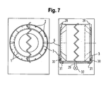
- Figure 7 features a diagram that represents the drum in a frontal and lateral semi-section view and, in the event of pockets 1 open at the minimum radius, shows the division of the toruses into pockets 1, the second valve shutter with axial actuation 2, the relative openings at the minimum radius 3, and in the lateral semi-section view, the accelerometer 28, the water supply conduits 29 that are part of the tub containing the drum 5, the actuation solenoids for the second valves 30, the solenoid valves for incoming flow controlling and timing 31, and the auxiliary pump for the injection of the balancing water 32.
- opening will have to occur by attracting the shutter 35 instead of repelling it, which is more complex, unless the water is drained towards the inside of the drum instead of outwards, and in this case the solenoid 34 could only act by solely attracting the ferromagnetic stainless steel spring 37, but in a less efficient manner from an energy consumption viewpoint.
Landscapes
- Engineering & Computer Science (AREA)
- Textile Engineering (AREA)
- Control Of Washing Machine And Dryer (AREA)
- Main Body Construction Of Washing Machines And Laundry Dryers (AREA)
Description
- The present Invention relates to a system to balance rotating inertia forces generated by poor distribution of laundry in a rotating drum in a washing machine having the drum placed in a tub, the system including a vibration measuring system, a controlling system and a system to generate counteracting forces and provided to regulate the Intensity thereof, in order to take into account progressive dewatering of the laundry during a centrifugation phase, the measuring system including a sensor, the control system comprising an electronic circuit and processor, and the system of generation of counteracting forces of variable intensity comprising a system of pockets open at the minimum radius, or watertight pockets, located at a circumference of the drum.
- It is well known that washing machines Including a tub for holding washing and rinsing liquid, systematically termed "water" herein, and a rotatable drum for holding laundry to be treated in washing, rinsing, end centrifugation phases, often vibrate during the centrifugation phase, sometimes quite heavily, and this is because of an uneven distribution of the laundry In the drum, which produces a system of forces on the washing machine. This system of forces, however, may gradually decreases in intensity as the laundry expels the water due to the said centrifugation, or possibly change due to different absorption characteristics of individual items.
- At present, on the one hand, these vibrations force manufacturers to make washing machines heavier by adding additional masses, and on the other hand, may require to reduce the diameter of the drum so that the tub containing it does not hit the outer structure including the casing of the washing machine, the tub being connected to the casing by a damping spring system. But the said limitation of the drum diameter is considered a negative factor, as it reduces the amount of laundry that can be washed per cycle.
- A system to balance a rotating inertia forces generated by a poor distributed laundry in a drum of a washing machine is disclosed in
US 5,829,084 A orUS 3,088,522 A . These systems comprise pockets mounted at the circumference of drum and fillable with water to generate counteracting forces and provided to regulate the intensity thereof. The system further comprises a control system which control vales for dewatering the pockets wherein the vales are operated by a mechanical force generated by a movement of the drum.US 5,829,084 A further disclose a system wherein the valves are controlled electrically by solenoids which generate a force if electrical contact will be closed due to said drum movement. - Apart from that, new special rates for nighttimes use of household electrical appliances available or considered to be made available in certain countries Including Italy provide a further stimulus in the reduction/elimination of the said vibrations, to enable use of washing machines during nighttimes without causing considerable noise.
- The goal of the present invention is therefore to provide a system that makes its possible to minimise or even completely eliminate the said vibrations. In prior art it has been considered to implement a system based on the use of shafts with eccentric masses whose radiuses could be varied. This system, however, is flawed in that it requires too extensive changes to the current architecture of a washing machine, and so it has been determined to propose a new system that obtains the same effects with fewer structural modifications.
- In accordance with the present invention there is provided a system to control vibrations during centrifugation in a domestic washing machine in accordance with the independent claim. Preferred embodiments of the invention are subjects of dependent claims or are exhibited in the subsequent description and the attached drawing.
- Accordingly there is provided, in accordance with the invention, a system to balance rotating inertia forces generated by poor distribution of laundry in a rotating drum in a washing machine having the drum placed in a tub, the system including a vibration measuring system, a controlling system and a system to generate counteracting forces and provided to regulate the intensity thereof, in order to take into account progressive dewatering of the laundry during a centrifugation phase, the measuring system including a sensor, the control system comprising an electronic circuit and processor, and the system of generation of counteracting forces of variable intensity comprising a system of pockets open at the minimum radius, or watertight pockets, located at a circumference of the drum, which may be filled with water via first valves controlled by the control system, and then selectively emptied via second valves also controlled by the control system, so as to generate a rotary force of equal intensity to that produced by the laundry but in the opposite direction and of variable intensity.
- The basic idea is to generate two toroidal cavities located laterally inside the drum, divided with dividers or by other suitable means into a series of pockets which may be filled with water, and may be selectively emptied in order to generate inertia forces able to offset those generated by a poor distribution of the laundry. Now these pockets can be constructed as integral elements of the drum and located inside or outside the circumference of the drum, or may even consist of additional plastic or metal elements installed in the drum. These pockets can be open at their respective minimum radius, or watertight and located internally, but with first valves for filling, located at the top, inside. Second valves, located in peripheral positions must be present however and must be used for the controlled drainage of the said pockets. Of course, it is clear that the first and second valves should be carefully controlled. Opening and closing can be controlled externally, by means - for example, but not exclusively - of the activation of solenoids located outside the tub, which generate electromagnetic forces when the first and second valves to be actuated are passed along. For the opening and closing of the first and second valves, there may be purely mechanical cam systems, present in the solenoids (although not part of the invention and particularly not preferable due to noise possibly produced by the inevitable impacts), or shutters made of ferromagnetic material, or - better still - permanent magnets, which can be attracted or repelled by appropriately reversing the current In the solenoids. An angle encoder can control the position of the drum, in order to detect when a particular valve will be in the right position to be actuated. However, the encoder could be replaced by analysts of the accelerations, possibly with the addition of field sensors (Hall effect or otherwise).
- It is noted that, by positioning the pockets on both sides of the drum, it is also easy to eliminate not only any directional force resulting from the system of centrifugal forces, but also any resulting momentum, with the further advantage of reducing the stress on the bearings that support the drum, as the latter would become Intrinsically balanced.
- In the event of use of pockets outside the circumference of the drum and open at the minimum radius, a small water supply conduit will be provided at the opening, which will deliver the water when the centrifugation cycle starts, so that all the pockets contain the same amount of water. At this point accelerometers assess the poor distribution and the said drainage valves can be opened with the systems mentioned above, thereby obtaining balance.
- In the event of an arrangement of intrinsically watertight pockets (which is more complex to actuate and therefore perhaps less preferable than the solution described above), the system may operate as follows: During a rinse phase preceding a centrifugation phase the drum is brought, in sequence, into positions with each pocket centred at the lowest point. The respective first valve is then opened until the pocket is completely full, and then the system moves on to the subsequent pocket. Then, when the centrifugation phase starts, it may initially be at low speed, in order to ascertain generation of low mechanical stress. But this makes it possible to determine the angular positions in which there are imbalances. Having done this, the additional useful imbalance can be calculated and water outlets can be activated from the pockets not needed to balance the rotating drum, leaving just enough water to obtain the desired result. This will be achieved by activating the drainage solenoids when the corresponding second valves pass along, all of which is controlled by the control device using the angle gauge, and however it is implemented. Of course, the second valves will have to be further actuated to offset the loss of weight of the laundry during the centrifugation phase.
- In accordance with a particularly preferred embodiment of the invention, the basic concept is to fill the pockets in the drum selectively at the beginning of the centrifugation phase, utilising first valves controlled in a timed fashion by the control system, after determining the position and entity of the unbalancing mass using appropriate sensoring means like accelerometers. In this way the second valves can be operated solely to correct minor errors and to gradually decrease the forces of inertia as the laundry is dewatered. In particular, the geometry of the washing machine and the drum may remain as described above, in the case of the pockets open at the inner radius filled from both sides, but what varies is the filling, which takes place in timed fashion after determining, by measurement, the entity and direction of the imbalance. It may be necessary to control the flow of water with appropriate first valves (one per side), filling the pockets in the first half of a round and then interrupting the supply during in the second half of the round, so as to drain the mass of water strictly necessary to balance out the imbalance into the pockets. The second valves will still be useful to adjust any supply error, but above all to gradually decrease the balancing mass as the laundry is dewatered.
- Note that, given the possibility of supplying the pockets located at the ends of the drum in a differential manner, in this case it is preferable to use two vibrometers or accelerometers as sensors, in order to balance the forces both tangentially and axially, so that the main axis of inertia of the rotating laundry/drum system coincides with the rotation axis, as tyre fitters do when positioning small balancing masses in different positions inside and outside of automobile wheels. However it is still possible to utilise a single vibrometer and settle for balancing solely the main component of the rotating forces.
- Preferred embodiments of the invention will now be described with reference to the Figures of the attached drawing. In particular, there are shown:
-
Fig. 1 is diagram representing the drum of the washing machine; -
Fig. 2 is a frontal view of solenoids controlling first valves; -
Fig. 3 shows solenoids arranged in a straight line instead of around a circumference; -
Fig. 4 shows second valves located axially rather than radially; -
Fig. 5 shows a first valve; -
Fig. 6 shows a magnetically actuated first valve; -
Fig. 7 shows a diagram that represents the drum in a frontal and lateral semi-section view; and -
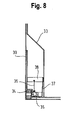
Fig. 8 shows the drum open at the lesser radius with several valve and control components and the tub. - Moving on to a more detailed description,
Figure 1 features a diagram that represents the drum in a frontal and lateral semi-section view and, in the event of pockets open at the minimum radius, shows the division of the toruses into pockets 1, the drainage valve shutter withaxial actuation 2, the relative openings at theminimum radius 3, and in the lateral semi-section view, the water supply conduits 4 that are part of the tub containing thedrum 5, and the actuation solenoids for thedrainage valves 6. - In the event of sealed pockets,
Figure 2 features a frontal view of both the solenoids that control the opening of the lowerfirst valves 7, for the filling, and of the upper second valves 8 to allow air to be released, which are located on the top of the pockets, inside, and the solenoids that control the second valves in the event ofradial control 9, while on the left-hand side of the semi-section view the shutters of thefirst valves 10 can be seen, and on the right-hand side the outside of the circumference of the drum is shown, with the radial second valves 11 visible. - Note that the second valves 11 can obviously be actuated both radially and axially, and applied to both open pockets and sealed ones; it has simply been decided to show the possible positions of the solenoids in the two Figures, without this rendering the use of one or the other type of actuation obligatory according to the chosen pocket type.
- Moving on to how the second valves 11 can be realised, a purely magnetic actuation method could be used, as illustrated in
Figure 3 , wherein thesolenoids 12 are shown arranged in a straight line instead of around a circumference, as will actually occur, and incorporated into thevalve shutter 13 is a permanent magnet, which is repulsed by a strong magnetic field generated by a series of solenoids located in parallel along the surface of the tub and provided with asoft iron core 14, so that the surfaces do not come into direct contact, as all they do is repulse the shutters so as to open the second valves 11, thereby activating solely thesolenoids 12 located at the passage of each respective second valve 11 to open. Obviously, these second valves 11 can be actuated both in a radial direction (but in this case the forces necessary for actuation will have to be much greater to overcome the centrifugal force) and in a direction parallel to the drum axis. Just as obviously, a ferromagnetic element could simply be incorporated into theshutter 13, which would open towards the outside because it was attracted thereto, rather than inwards because it was repulsed, but in the first case a higher current intensity would be required. - In the event of second valves 11 located axially rather than radially, this would result in the need to house the
solenoids 12 outside the tub, but actuating them would require a much lower current. All this is shown inFigure 4 , where 15 denotes the drum open at the lesser radius, 16 denotes the solenoid, 17 is the shutter and the permanent magnet therefor, 18 is a rocker, 19 a stainless steel spring, 20 is the valve support and 21 is the tub. The axis of the drum is not shown as it is horizontal, but very distant. If use of thepermanent magnet 17 is not desirable (even though thesemagnets 17 do not risk losing their magnetisation characteristics as the maximum temperatures reached by a washing machine during washing are well below the Curie temperature), opening will have to occur by attracting the shutter 134 instead of repelling it, which is more complex, unless the water is drained towards the inside of the drum instead of outwards, and in this case thesolenoid 12 could only act by solely attracting the ferromagneticstainless steel spring 19, but in a less efficient manner from an energy consumption viewpoint. - As far as the first valves are concerned, these can be realized as shown, for example, in
Figure 5 , by way of a non-limiting example of a preferred embodiment. On the left, the valve is closed; on the right it is open. Note that in this case, the opening is controlled by the solenoid 22 located on thetub 23, which acts from outside thedrum 24, by pressing directly on thevalve stem 25, since - in this case - the drum is stationary, while the valve is open towards the inner surface of thebag 26. -
Figure 6 shows a magnetically actuated first valve, therefore without a contact, where the presence of apermanent magnet 27 can be seen. - As to a particularly preferred embodiment of the invention,
Figure 7 features a diagram that represents the drum in a frontal and lateral semi-section view and, in the event of pockets 1 open at the minimum radius, shows the division of the toruses into pockets 1, the second valve shutter withaxial actuation 2, the relative openings at theminimum radius 3, and in the lateral semi-section view, theaccelerometer 28, thewater supply conduits 29 that are part of the tub containing thedrum 5, the actuation solenoids for thesecond valves 30, the solenoid valves for incoming flow controlling andtiming 31, and the auxiliary pump for the injection of the balancingwater 32. - Moving on to explain how the drainage valves with radial actuation can be realised, this is shown in
Figure 8 , where 33 denotes the drum open at the lesser radius, 34 denotes the solenoid, 35 is the shutter and the permanent magnet therefor, 36 is a rocker, 37 a stainless steel spring, 38 the valve support and 39 is the tub. The axis of the drum is not shown as it is horizontal, but very distant. If use of thepermanent magnets 35 is not desirable (even though thesemagnets 35 do not risk losing their magnetisation characteristics as the maximum temperatures reached by a washing machine during washing are well below the Curie temperature), opening will have to occur by attracting theshutter 35 instead of repelling it, which is more complex, unless the water is drained towards the inside of the drum instead of outwards, and in this case thesolenoid 34 could only act by solely attracting the ferromagneticstainless steel spring 37, but in a less efficient manner from an energy consumption viewpoint.
Claims (13)
- System to balance rotating inertia forces generated by poor distribution of laundry in a rotating drum (5, 15, 24) in a washing machine having the drum (5, 15, 24) placed in a tub (21, 23, 39), the system including a vibration measuring system, a controlling system and a system to generate counteracting forces and provided to regulate the intensity thereof, in order to take into account progressive dewatering of the laundry during a centrifugation phase, the measuring system including a sensor (28), and the system of generation of counteracting forces of variable intensity comprising a system of pockets (1) open at the minimum radius (3, 33), or watertight pockets, located at a circumference of the drum (5, 15, 24), which may be filled with water (32) via first valves (7, 10) controlled by the control system, and then selectively emptied via second valves (8, 11, 30) also controlled by the control system, so as to generate a rotary force of equal intensity to that produced by the laundry but in the opposite direction and of variable intensity, wherein the opening and closing of the valves (8, 11, 30) are controlled by means of the activation of solenoids (12, 16, 22) which generate electromagnetic forces when the first and second valves (7, 8, 10, 11, 30) to be actuated are passed along and the first and second valves (7, 8, 10, 11, 30) are shutters (13, 17, 35, 134) incorporating ferromagnetic material or permanent magnets (17, 27),
which can be attracted or repelled by appropriately reversing the current in the solenoids (12, 16, 22) characterised in that the control system comprising an electronic circuit and processor and a series of said solenoids (12, 16, 22) are located in parallel along the surface of the tub (21, 23, 39). - System according to claim 1, wherein the shutter (13, 17, 35, 134) is repulsed by a strong magnetic field by said series of solenoids (12, 16, 22) provided with a soft iron core (14), so that the surfaces of the shutter (13, 17, 35, 134) and the soft iron core (14) do not come into direct contact, as all they do is to repulse shutters so as to open the second valves (11).
- System in accordance with one of claims 1 and 2, wherein the sensor includes at least one of a vibrometer, an accelerometer (28), and a solenoid which measures the motion either in the tub or in the washing machine structure.
- System to balance rotating inertia forces generated by poor distribution of the laundry in a washing machine, in accordance with any previous claim, wherein the system of pockets (1) is an integral part of the drum (5, 15, 24).
- System to balance rotating inertia forces generated by poor distribution of the laundry in a washing machine, in accordance with any previous claim, wherein the pockets (1) are open at a minimum radius (3, 33) and located outside the circumference of the drum (5, 15, 24).
- System to balance rotating inertia forces generated by poor distribution of the laundry in a washing machine, in accordance with any of claims 1 to 4, wherein the watertight pockets are located inside the circumference of the drum (5, 15, 24).
- System to balance rotating inertia forces generated by poor distribution of the laundry in a washing machine, in accordance with any previous claim, wherein the first valves (7, 10) are positioned on respective inner surfaces of the pockets (1), at a distance from the rotational axis, and wherein the first valves (7, 10) are controlled from outside the tub by suitable electronically controlled actuation systems of the control system, for filling the pockets with water (32) as they are in their respective lowest positions upon rotating the drum (5, 15, 24).
- System in accordance with claim 7, wherein the actuation systems comprise solenoids (12, 16, 22) for acting on the first valves through one of cams (25) and magnetic means (27).
- System in accordance with one of claims 7 and 8, wherein the first valves may open in either axial or radial directions by one of attraction and repulsion of ferromagnetic material included in the respective actuation systems.
- System to balance rotating inertia forces generated by poor distribution of the laundry in a washing machine in accordance with any previous claim, wherein electronically controlled actuation devices are provided for the second valves (8, 11, 30) to actuate the second valves (8, 11, 30) in a timely and appropriate fashion during drum rotation.
- System in accordance with claim 10, wherein the actuation systems for the second valves (8, 11, 30) comprise solenoids (34) for acting on the second valves (8, 11, 30) through one of cams and magnetic means.
- System in accordance with one of claims 10 and 11, wherein the second valves (8, 11, 30) may open in either axial or radial directions by one of attraction and repulsion of ferromagnetic material included in the actuation systems.
- System in accodance with any previous claim, wherein the control device is programmed so as to only fill the pockets (1) positioned opposite any unbalancing mass detected by the controlling system with water (32), and then selectively emptied via the second valves (8, 11, 30) so as to generate a rotary force of equal intensity to that produced by the laundry but in the opposite direction and of variable intensity.
Priority Applications (1)
| Application Number | Priority Date | Filing Date | Title |
|---|---|---|---|
| PL11785432T PL2643511T3 (en) | 2010-11-22 | 2011-11-22 | System to balance rotating inertia forces during centrifugation in a washing machine |
Applications Claiming Priority (3)
| Application Number | Priority Date | Filing Date | Title |
|---|---|---|---|
| ITCS2010A000017A IT1405485B1 (en) | 2010-11-22 | 2010-11-22 | SYSTEM FOR VIBRATION CONTROL DURING CENTRIFUGATION IN A HOME WASHING MACHINE. |
| IT000006A ITCS20110006A1 (en) | 2011-03-02 | 2011-03-02 | BALANCING SYSTEM FOR ROTATING INERTIA FORCES GENERATED BY THE MALDISTRIBUTION OF CLOTHS IN A WASHING MACHINE |
| PCT/EP2011/070692 WO2012069479A2 (en) | 2010-11-22 | 2011-11-22 | System to balance rotating inertia forces during centrifugation in a washing machine |
Publications (2)
| Publication Number | Publication Date |
|---|---|
| EP2643511A2 EP2643511A2 (en) | 2013-10-02 |
| EP2643511B1 true EP2643511B1 (en) | 2015-10-14 |
Family
ID=45001769
Family Applications (1)
| Application Number | Title | Priority Date | Filing Date |
|---|---|---|---|
| EP11785432.3A Active EP2643511B1 (en) | 2010-11-22 | 2011-11-22 | System to balance rotating inertia forces during centrifugation in a washing machine |
Country Status (3)
| Country | Link |
|---|---|
| EP (1) | EP2643511B1 (en) |
| PL (1) | PL2643511T3 (en) |
| WO (1) | WO2012069479A2 (en) |
Families Citing this family (1)
| Publication number | Priority date | Publication date | Assignee | Title |
|---|---|---|---|---|
| GB2566475A (en) * | 2017-09-14 | 2019-03-20 | Tochi Tech Ltd | Washing machine water circulation system |
Family Cites Families (3)
| Publication number | Priority date | Publication date | Assignee | Title |
|---|---|---|---|---|
| DE1108170B (en) * | 1958-12-31 | 1961-06-08 | Bbc Brown Boveri & Cie | Device for balancing out the unbalance in washing machines and spin dryers with a horizontal shaft |
| US5582040A (en) * | 1995-08-09 | 1996-12-10 | Khan; Aman U. | Water balancing apparatus for horizontal axis and vertical axis laundry appliances |
| US5829084A (en) * | 1997-06-02 | 1998-11-03 | Fujiwara; Leslie H. | Method and system for balancing an upright washing machine |
-
2011
- 2011-11-22 WO PCT/EP2011/070692 patent/WO2012069479A2/en not_active Ceased
- 2011-11-22 EP EP11785432.3A patent/EP2643511B1/en active Active
- 2011-11-22 PL PL11785432T patent/PL2643511T3/en unknown
Also Published As
| Publication number | Publication date |
|---|---|
| EP2643511A2 (en) | 2013-10-02 |
| WO2012069479A3 (en) | 2012-11-08 |
| WO2012069479A2 (en) | 2012-05-31 |
| PL2643511T3 (en) | 2016-03-31 |
Similar Documents
| Publication | Publication Date | Title |
|---|---|---|
| US9121126B2 (en) | Washing machine and control method thereof | |
| WO2018184734A1 (en) | Laundry treating apparatus | |
| CA2281071C (en) | Method and apparatus for operating an automatic balancing system | |
| EP2594675A1 (en) | Washing machine having vibration reducing apparatus and vibration reducing method using the same | |
| CN114846194B (en) | Laundry equipment with dynamic balancing components | |
| EP2568070A1 (en) | Washing machine | |
| EP2759628A2 (en) | Washing machine | |
| US11976403B2 (en) | Laundry treating appliance | |
| EP1506355B1 (en) | Automatic balancing device | |
| KR102541409B1 (en) | Washing machine | |
| EP2643511A2 (en) | System to balance rotating inertia forces during centrifugation in a washing machine | |
| EP2759629B1 (en) | Washing machine | |
| CN114846193B (en) | Suspension-free laundry equipment and method for balancing the laundry equipment | |
| CN106906609B (en) | Household appliance for caring for articles of clothing and method for operating the household appliance | |
| CN114846192B (en) | Dynamically balanced assembly with one or more springs and laundry equipment | |
| KR20140095929A (en) | Washing machine | |
| US20230017731A1 (en) | Washing machine and method of increasing balance of the drum of the washing machine | |
| JP2017077090A (en) | Permanent magnet rotating electric machine and washing machine | |
| US9145634B2 (en) | Method of operating a laundry treating appliance | |
| CN206581032U (en) | The bascule and washing machine of a kind of interior bucket of washing machine | |
| EP4405523A1 (en) | Actuator for the active balancing of a washing machine | |
| KR102334616B1 (en) | Laundry Treating Apparatus and Control Method for the same | |
| EP3130695B1 (en) | Balance ring assembly | |
| CN105978190A (en) | Low-noise switched reluctance motor | |
| EP4353891A1 (en) | A method for operating a washing machine and washing machine |
Legal Events
| Date | Code | Title | Description |
|---|---|---|---|
| PUAI | Public reference made under article 153(3) epc to a published international application that has entered the european phase |
Free format text: ORIGINAL CODE: 0009012 |
|
| 17P | Request for examination filed |
Effective date: 20130624 |
|
| AK | Designated contracting states |
Kind code of ref document: A2 Designated state(s): AL AT BE BG CH CY CZ DE DK EE ES FI FR GB GR HR HU IE IS IT LI LT LU LV MC MK MT NL NO PL PT RO RS SE SI SK SM TR |
|
| RIN1 | Information on inventor provided before grant (corrected) |
Inventor name: DANIELI, GUIDO Inventor name: INNOCENTI, CARLO |
|
| DAX | Request for extension of the european patent (deleted) | ||
| RIN1 | Information on inventor provided before grant (corrected) |
Inventor name: INNOCENTI, CARLO Inventor name: DANIELI, GUIDO |
|
| RAP1 | Party data changed (applicant data changed or rights of an application transferred) |
Owner name: BSH HAUSGERAETE GMBH |
|
| GRAP | Despatch of communication of intention to grant a patent |
Free format text: ORIGINAL CODE: EPIDOSNIGR1 |
|
| INTG | Intention to grant announced |
Effective date: 20150407 |
|
| GRAP | Despatch of communication of intention to grant a patent |
Free format text: ORIGINAL CODE: EPIDOSNIGR1 |
|
| GRAS | Grant fee paid |
Free format text: ORIGINAL CODE: EPIDOSNIGR3 |
|
| GRAA | (expected) grant |
Free format text: ORIGINAL CODE: 0009210 |
|
| INTG | Intention to grant announced |
Effective date: 20150831 |
|
| AK | Designated contracting states |
Kind code of ref document: B1 Designated state(s): AL AT BE BG CH CY CZ DE DK EE ES FI FR GB GR HR HU IE IS IT LI LT LU LV MC MK MT NL NO PL PT RO RS SE SI SK SM TR |
|
| REG | Reference to a national code |
Ref country code: GB Ref legal event code: FG4D |
|
| REG | Reference to a national code |
Ref country code: AT Ref legal event code: REF Ref document number: 755152 Country of ref document: AT Kind code of ref document: T Effective date: 20151015 Ref country code: CH Ref legal event code: EP |
|
| REG | Reference to a national code |
Ref country code: IE Ref legal event code: FG4D |
|
| REG | Reference to a national code |
Ref country code: DE Ref legal event code: R096 Ref document number: 602011020649 Country of ref document: DE |
|
| REG | Reference to a national code |
Ref country code: NL Ref legal event code: MP Effective date: 20151014 |
|
| REG | Reference to a national code |
Ref country code: LT Ref legal event code: MG4D |
|
| REG | Reference to a national code |
Ref country code: AT Ref legal event code: MK05 Ref document number: 755152 Country of ref document: AT Kind code of ref document: T Effective date: 20151014 |
|
| PG25 | Lapsed in a contracting state [announced via postgrant information from national office to epo] |
Ref country code: NO Free format text: LAPSE BECAUSE OF FAILURE TO SUBMIT A TRANSLATION OF THE DESCRIPTION OR TO PAY THE FEE WITHIN THE PRESCRIBED TIME-LIMIT Effective date: 20160114 Ref country code: LT Free format text: LAPSE BECAUSE OF FAILURE TO SUBMIT A TRANSLATION OF THE DESCRIPTION OR TO PAY THE FEE WITHIN THE PRESCRIBED TIME-LIMIT Effective date: 20151014 Ref country code: ES Free format text: LAPSE BECAUSE OF FAILURE TO SUBMIT A TRANSLATION OF THE DESCRIPTION OR TO PAY THE FEE WITHIN THE PRESCRIBED TIME-LIMIT Effective date: 20151014 Ref country code: HR Free format text: LAPSE BECAUSE OF FAILURE TO SUBMIT A TRANSLATION OF THE DESCRIPTION OR TO PAY THE FEE WITHIN THE PRESCRIBED TIME-LIMIT Effective date: 20151014 Ref country code: IS Free format text: LAPSE BECAUSE OF FAILURE TO SUBMIT A TRANSLATION OF THE DESCRIPTION OR TO PAY THE FEE WITHIN THE PRESCRIBED TIME-LIMIT Effective date: 20160214 Ref country code: NL Free format text: LAPSE BECAUSE OF FAILURE TO SUBMIT A TRANSLATION OF THE DESCRIPTION OR TO PAY THE FEE WITHIN THE PRESCRIBED TIME-LIMIT Effective date: 20151014 |
|
| PG25 | Lapsed in a contracting state [announced via postgrant information from national office to epo] |
Ref country code: GR Free format text: LAPSE BECAUSE OF FAILURE TO SUBMIT A TRANSLATION OF THE DESCRIPTION OR TO PAY THE FEE WITHIN THE PRESCRIBED TIME-LIMIT Effective date: 20160115 Ref country code: PT Free format text: LAPSE BECAUSE OF FAILURE TO SUBMIT A TRANSLATION OF THE DESCRIPTION OR TO PAY THE FEE WITHIN THE PRESCRIBED TIME-LIMIT Effective date: 20160215 Ref country code: RS Free format text: LAPSE BECAUSE OF FAILURE TO SUBMIT A TRANSLATION OF THE DESCRIPTION OR TO PAY THE FEE WITHIN THE PRESCRIBED TIME-LIMIT Effective date: 20151014 Ref country code: AT Free format text: LAPSE BECAUSE OF FAILURE TO SUBMIT A TRANSLATION OF THE DESCRIPTION OR TO PAY THE FEE WITHIN THE PRESCRIBED TIME-LIMIT Effective date: 20151014 Ref country code: FI Free format text: LAPSE BECAUSE OF FAILURE TO SUBMIT A TRANSLATION OF THE DESCRIPTION OR TO PAY THE FEE WITHIN THE PRESCRIBED TIME-LIMIT Effective date: 20151014 Ref country code: LV Free format text: LAPSE BECAUSE OF FAILURE TO SUBMIT A TRANSLATION OF THE DESCRIPTION OR TO PAY THE FEE WITHIN THE PRESCRIBED TIME-LIMIT Effective date: 20151014 Ref country code: SE Free format text: LAPSE BECAUSE OF FAILURE TO SUBMIT A TRANSLATION OF THE DESCRIPTION OR TO PAY THE FEE WITHIN THE PRESCRIBED TIME-LIMIT Effective date: 20151014 |
|
| REG | Reference to a national code |
Ref country code: CH Ref legal event code: PL |
|
| REG | Reference to a national code |
Ref country code: DE Ref legal event code: R097 Ref document number: 602011020649 Country of ref document: DE |
|
| PG25 | Lapsed in a contracting state [announced via postgrant information from national office to epo] |
Ref country code: MC Free format text: LAPSE BECAUSE OF FAILURE TO SUBMIT A TRANSLATION OF THE DESCRIPTION OR TO PAY THE FEE WITHIN THE PRESCRIBED TIME-LIMIT Effective date: 20151014 Ref country code: LI Free format text: LAPSE BECAUSE OF NON-PAYMENT OF DUE FEES Effective date: 20151130 Ref country code: CZ Free format text: LAPSE BECAUSE OF FAILURE TO SUBMIT A TRANSLATION OF THE DESCRIPTION OR TO PAY THE FEE WITHIN THE PRESCRIBED TIME-LIMIT Effective date: 20151014 Ref country code: CH Free format text: LAPSE BECAUSE OF NON-PAYMENT OF DUE FEES Effective date: 20151130 |
|
| PLBE | No opposition filed within time limit |
Free format text: ORIGINAL CODE: 0009261 |
|
| STAA | Information on the status of an ep patent application or granted ep patent |
Free format text: STATUS: NO OPPOSITION FILED WITHIN TIME LIMIT |
|
| REG | Reference to a national code |
Ref country code: IE Ref legal event code: MM4A |
|
| REG | Reference to a national code |
Ref country code: FR Ref legal event code: ST Effective date: 20160729 |
|
| PG25 | Lapsed in a contracting state [announced via postgrant information from national office to epo] |
Ref country code: DK Free format text: LAPSE BECAUSE OF FAILURE TO SUBMIT A TRANSLATION OF THE DESCRIPTION OR TO PAY THE FEE WITHIN THE PRESCRIBED TIME-LIMIT Effective date: 20151014 Ref country code: SK Free format text: LAPSE BECAUSE OF FAILURE TO SUBMIT A TRANSLATION OF THE DESCRIPTION OR TO PAY THE FEE WITHIN THE PRESCRIBED TIME-LIMIT Effective date: 20151014 Ref country code: EE Free format text: LAPSE BECAUSE OF FAILURE TO SUBMIT A TRANSLATION OF THE DESCRIPTION OR TO PAY THE FEE WITHIN THE PRESCRIBED TIME-LIMIT Effective date: 20151014 Ref country code: SM Free format text: LAPSE BECAUSE OF FAILURE TO SUBMIT A TRANSLATION OF THE DESCRIPTION OR TO PAY THE FEE WITHIN THE PRESCRIBED TIME-LIMIT Effective date: 20151014 Ref country code: RO Free format text: LAPSE BECAUSE OF FAILURE TO SUBMIT A TRANSLATION OF THE DESCRIPTION OR TO PAY THE FEE WITHIN THE PRESCRIBED TIME-LIMIT Effective date: 20151014 |
|
| 26N | No opposition filed |
Effective date: 20160715 |
|
| GBPC | Gb: european patent ceased through non-payment of renewal fee |
Effective date: 20160114 |
|
| PG25 | Lapsed in a contracting state [announced via postgrant information from national office to epo] |
Ref country code: IE Free format text: LAPSE BECAUSE OF NON-PAYMENT OF DUE FEES Effective date: 20151122 Ref country code: GB Free format text: LAPSE BECAUSE OF NON-PAYMENT OF DUE FEES Effective date: 20160114 |
|
| PG25 | Lapsed in a contracting state [announced via postgrant information from national office to epo] |
Ref country code: FR Free format text: LAPSE BECAUSE OF NON-PAYMENT OF DUE FEES Effective date: 20151214 Ref country code: SI Free format text: LAPSE BECAUSE OF FAILURE TO SUBMIT A TRANSLATION OF THE DESCRIPTION OR TO PAY THE FEE WITHIN THE PRESCRIBED TIME-LIMIT Effective date: 20151014 |
|
| PG25 | Lapsed in a contracting state [announced via postgrant information from national office to epo] |
Ref country code: BE Free format text: LAPSE BECAUSE OF FAILURE TO SUBMIT A TRANSLATION OF THE DESCRIPTION OR TO PAY THE FEE WITHIN THE PRESCRIBED TIME-LIMIT Effective date: 20151014 |
|
| PG25 | Lapsed in a contracting state [announced via postgrant information from national office to epo] |
Ref country code: HU Free format text: LAPSE BECAUSE OF FAILURE TO SUBMIT A TRANSLATION OF THE DESCRIPTION OR TO PAY THE FEE WITHIN THE PRESCRIBED TIME-LIMIT; INVALID AB INITIO Effective date: 20111122 Ref country code: BG Free format text: LAPSE BECAUSE OF FAILURE TO SUBMIT A TRANSLATION OF THE DESCRIPTION OR TO PAY THE FEE WITHIN THE PRESCRIBED TIME-LIMIT Effective date: 20151014 |
|
| PG25 | Lapsed in a contracting state [announced via postgrant information from national office to epo] |
Ref country code: CY Free format text: LAPSE BECAUSE OF FAILURE TO SUBMIT A TRANSLATION OF THE DESCRIPTION OR TO PAY THE FEE WITHIN THE PRESCRIBED TIME-LIMIT Effective date: 20151014 |
|
| PG25 | Lapsed in a contracting state [announced via postgrant information from national office to epo] |
Ref country code: MT Free format text: LAPSE BECAUSE OF FAILURE TO SUBMIT A TRANSLATION OF THE DESCRIPTION OR TO PAY THE FEE WITHIN THE PRESCRIBED TIME-LIMIT Effective date: 20151014 |
|
| PG25 | Lapsed in a contracting state [announced via postgrant information from national office to epo] |
Ref country code: LU Free format text: LAPSE BECAUSE OF NON-PAYMENT OF DUE FEES Effective date: 20151122 |
|
| PG25 | Lapsed in a contracting state [announced via postgrant information from national office to epo] |
Ref country code: MK Free format text: LAPSE BECAUSE OF FAILURE TO SUBMIT A TRANSLATION OF THE DESCRIPTION OR TO PAY THE FEE WITHIN THE PRESCRIBED TIME-LIMIT Effective date: 20151014 |
|
| PG25 | Lapsed in a contracting state [announced via postgrant information from national office to epo] |
Ref country code: AL Free format text: LAPSE BECAUSE OF FAILURE TO SUBMIT A TRANSLATION OF THE DESCRIPTION OR TO PAY THE FEE WITHIN THE PRESCRIBED TIME-LIMIT Effective date: 20151014 |
|
| REG | Reference to a national code |
Ref country code: DE Ref legal event code: R084 Ref document number: 602011020649 Country of ref document: DE |
|
| PGFP | Annual fee paid to national office [announced via postgrant information from national office to epo] |
Ref country code: IT Payment date: 20191120 Year of fee payment: 9 Ref country code: PL Payment date: 20191114 Year of fee payment: 9 |
|
| PGFP | Annual fee paid to national office [announced via postgrant information from national office to epo] |
Ref country code: TR Payment date: 20191119 Year of fee payment: 9 |
|
| PG25 | Lapsed in a contracting state [announced via postgrant information from national office to epo] |
Ref country code: IT Free format text: LAPSE BECAUSE OF NON-PAYMENT OF DUE FEES Effective date: 20201122 |
|
| PG25 | Lapsed in a contracting state [announced via postgrant information from national office to epo] |
Ref country code: TR Free format text: LAPSE BECAUSE OF NON-PAYMENT OF DUE FEES Effective date: 20201122 |
|
| PG25 | Lapsed in a contracting state [announced via postgrant information from national office to epo] |
Ref country code: PL Free format text: LAPSE BECAUSE OF NON-PAYMENT OF DUE FEES Effective date: 20201122 |
|
| PGFP | Annual fee paid to national office [announced via postgrant information from national office to epo] |
Ref country code: DE Payment date: 20241130 Year of fee payment: 14 |