EP2642956B1 - Valve for ostomy pouch - Google Patents
Valve for ostomy pouch Download PDFInfo
- Publication number
- EP2642956B1 EP2642956B1 EP11791404.4A EP11791404A EP2642956B1 EP 2642956 B1 EP2642956 B1 EP 2642956B1 EP 11791404 A EP11791404 A EP 11791404A EP 2642956 B1 EP2642956 B1 EP 2642956B1
- Authority
- EP
- European Patent Office
- Prior art keywords
- valve
- stem
- region
- grasping
- pouch
- Prior art date
- Legal status (The legal status is an assumption and is not a legal conclusion. Google has not performed a legal analysis and makes no representation as to the accuracy of the status listed.)
- Active
Links
- 239000000463 material Substances 0.000 claims description 19
- 239000012530 fluid Substances 0.000 claims description 13
- 210000001124 body fluid Anatomy 0.000 claims description 7
- 229920002725 thermoplastic elastomer Polymers 0.000 claims description 5
- 239000010839 body fluid Substances 0.000 claims description 4
- 238000004891 communication Methods 0.000 claims description 3
- 239000007779 soft material Substances 0.000 claims 1
- 230000008901 benefit Effects 0.000 description 6
- 238000007789 sealing Methods 0.000 description 6
- 230000000007 visual effect Effects 0.000 description 5
- 230000015572 biosynthetic process Effects 0.000 description 3
- 229920001903 high density polyethylene Polymers 0.000 description 3
- 239000004700 high-density polyethylene Substances 0.000 description 3
- 230000013011 mating Effects 0.000 description 3
- 238000000034 method Methods 0.000 description 3
- 239000002699 waste material Substances 0.000 description 3
- 230000000694 effects Effects 0.000 description 2
- 239000010808 liquid waste Substances 0.000 description 2
- 238000012986 modification Methods 0.000 description 2
- 230000004048 modification Effects 0.000 description 2
- 239000004033 plastic Substances 0.000 description 2
- 229920003023 plastic Polymers 0.000 description 2
- 230000000284 resting effect Effects 0.000 description 2
- 239000004743 Polypropylene Substances 0.000 description 1
- 210000001015 abdomen Anatomy 0.000 description 1
- 230000004888 barrier function Effects 0.000 description 1
- 230000000295 complement effect Effects 0.000 description 1
- 230000002452 interceptive effect Effects 0.000 description 1
- 230000014759 maintenance of location Effects 0.000 description 1
- -1 polypropylene Polymers 0.000 description 1
- 229920001155 polypropylene Polymers 0.000 description 1
- 239000011347 resin Substances 0.000 description 1
- 229920005989 resin Polymers 0.000 description 1
- 230000000717 retained effect Effects 0.000 description 1
- 239000012748 slip agent Substances 0.000 description 1
- 230000002485 urinary effect Effects 0.000 description 1
- XLYOFNOQVPJJNP-UHFFFAOYSA-N water Substances O XLYOFNOQVPJJNP-UHFFFAOYSA-N 0.000 description 1
Images






Classifications
-
- A—HUMAN NECESSITIES
- A61—MEDICAL OR VETERINARY SCIENCE; HYGIENE
- A61F—FILTERS IMPLANTABLE INTO BLOOD VESSELS; PROSTHESES; DEVICES PROVIDING PATENCY TO, OR PREVENTING COLLAPSING OF, TUBULAR STRUCTURES OF THE BODY, e.g. STENTS; ORTHOPAEDIC, NURSING OR CONTRACEPTIVE DEVICES; FOMENTATION; TREATMENT OR PROTECTION OF EYES OR EARS; BANDAGES, DRESSINGS OR ABSORBENT PADS; FIRST-AID KITS
- A61F5/00—Orthopaedic methods or devices for non-surgical treatment of bones or joints; Nursing devices ; Anti-rape devices
- A61F5/44—Devices worn by the patient for reception of urine, faeces, catamenial or other discharge; Colostomy devices
- A61F5/4404—Details or parts
- A61F5/4405—Valves or valve arrangements specially adapted therefor ; Fluid inlets or outlets
-
- A—HUMAN NECESSITIES
- A61—MEDICAL OR VETERINARY SCIENCE; HYGIENE
- A61F—FILTERS IMPLANTABLE INTO BLOOD VESSELS; PROSTHESES; DEVICES PROVIDING PATENCY TO, OR PREVENTING COLLAPSING OF, TUBULAR STRUCTURES OF THE BODY, e.g. STENTS; ORTHOPAEDIC, NURSING OR CONTRACEPTIVE DEVICES; FOMENTATION; TREATMENT OR PROTECTION OF EYES OR EARS; BANDAGES, DRESSINGS OR ABSORBENT PADS; FIRST-AID KITS
- A61F5/00—Orthopaedic methods or devices for non-surgical treatment of bones or joints; Nursing devices ; Anti-rape devices
- A61F5/44—Devices worn by the patient for reception of urine, faeces, catamenial or other discharge; Colostomy devices
- A61F5/445—Colostomy, ileostomy or urethrostomy devices
-
- F—MECHANICAL ENGINEERING; LIGHTING; HEATING; WEAPONS; BLASTING
- F16—ENGINEERING ELEMENTS AND UNITS; GENERAL MEASURES FOR PRODUCING AND MAINTAINING EFFECTIVE FUNCTIONING OF MACHINES OR INSTALLATIONS; THERMAL INSULATION IN GENERAL
- F16K—VALVES; TAPS; COCKS; ACTUATING-FLOATS; DEVICES FOR VENTING OR AERATING
- F16K3/00—Gate valves or sliding valves, i.e. cut-off apparatus with closing members having a sliding movement along the seat for opening and closing
- F16K3/22—Gate valves or sliding valves, i.e. cut-off apparatus with closing members having a sliding movement along the seat for opening and closing with sealing faces shaped as surfaces of solids of revolution
- F16K3/24—Gate valves or sliding valves, i.e. cut-off apparatus with closing members having a sliding movement along the seat for opening and closing with sealing faces shaped as surfaces of solids of revolution with cylindrical valve members
Definitions
- the present disclosure is directed to a valve for an ostomy pouch. More particularly, the present disclosure pertains to a valve, for draining liquid waste or bodily fluids such as, for example, from a urostomy pouch, the valve having one or more features providing visual and tactile indication of the state of the valve.
- a valve according to the preamble of claim 1 is known from GB 202 032 A and also WO 2011/091798 .
- Another valve is known from GB 2 125 130 A .
- a urostomy appliance or pouch is a medical device that provides a means for the collection of liquid waste formed via an opening into the urinary system, that is diverted externally of the body through a stoma.
- the waste collected in the pouch is retained in the pouch, for example, during the daytime, so that the user can discharge or empty the pouch at a convenient time and location.
- the waste can also be routed through the pouch, for example, during the evening, directly to a remote collection container.
- a valve is disposed at the bottom or discharge end of the pouch.
- a typical valve is a plastic ball-cock or pet-cock type-valve that includes a fixed body and a rotating cylindrical valve stem. An opening in the body provides fluid communication from the pouch into a circumferentially disposed section of the body on a side of the stem.
- the stem includes an opening that extends circumferentially about a portion of the stem that is open to a central opening in the stem. In this manner the stem is rotated 180 degrees between an open position, in which the body opening and stem opening are aligned and a closed position, in which the body opening and the stem opening are not in alignment.
- the stem extends through and below the body and includes a flange that extends radially outwardly from the stem.
- the flange provides a finger rest to allow a user to rotate the stem between the open and closed positions.
- One known valve includes printed indicia (a printed drop) on the flange to provide visual indicate of the position of the valve. For example, when the indicia is visible (away from the user's body), the valve may be in the open position, and when the indicia is not visible or is facing the user's body, the valve may be in the closed position.
- the valve is located at the bottom of the pouch, and the pouch is typically secured to the users abdomen above or at about the waistline area.
- the pouch is typically secured to the users abdomen above or at about the waistline area.
- valve for a urostomy pouch that provide positive indication of the state or position of the valve.
- a valve provides both visual and tactile indication of the valve position.
- a valve is sealable to an associated container, such as an ostomy pouch.
- An exemplary pouch has an interior, and the valve is adapted to permit and stop flow of fluid from the pouch.
- the valve includes a valve body sealable to the container.
- the valve body has a stem receiver formed therein.
- the valve body includes a fluid receiving region in communication with the pouch interior.
- a stem is mounted to the valve body and has a hollow central portion and a sealed upper portion.
- the stem is positioned in the stem receiving region and is adapted for rotation within the stem receiving region.
- the stem includes a stem opening in a portion of a wall thereof. The stem is rotatable between an open position to align the stem opening with the valve body fluid receiving region to permit flow from the pouch through the valve, and a closed position to misalign the stem opening with the valve body fluid receiving region to stop flow through the valve.
- the stem has a grasping region spaced from the valve body.
- the grasping region is adapted to rotate the stem within the stem receiving region to move the valve between the open and closed positions.
- the grasping region includes a tactile indicator to provide indication of the valve position. Such a valve provides both visual and tactile positive indication of the state or position of the valve.
- the grasping region can be formed with drainage openings therein.
- a urostomy pouch 10 having a body 12 formed by, for example, sealing two films 14a,b to one another about their respective peripheries 16 to define an interior storage region 17.
- the bottom 18 of the pouch 10 includes an opening 20 into which a valve 22 is fitted and secured.
- the films 14a,b can be sealed to one another by methods such a heat sealing and the like; the valve 22 being similarly sealed to the pouch 10 at the bottom opening 20.
- Suitable methods for sealing the pouch walls/films 14 to one another and valve 22 to the pouch films 14 will be recognized by those skilled in the art.
- bottom is intended to refer to the lower portion of the pouch 10 and/or valve 22 when the pouch 10 is adhered to a user's body.
- the pouch 110 also includes an input opening 124 through which waste is input to the pouch 110 from a stoma.
- the input opening 124 is adhered to the user by a barrier (not shown) in a one-piece or two-piece configuration (the two-piece configuration being shown generally at 126, in FIG. 4 ), which configurations will also be recognized by those skilled in the art.
- the valve 22 is attached and sealed to the pouch bottom 18. Accordingly, the valve 22 includes a body 28 that is sealed to the pouch films 14a,b and a stem portion 30 that is supported in and by the body 28.
- the stem portion 30 is movable, e.g., rotatable, to open and close the valve 22 (e.g., to permit and isolate flow from the pouch 10).
- the valve body 28 is of a known design and, as seen in FIG. 1 , has a generally elongated honeycomb shape having diverging/converging ends 32 and an elongated central portion 34.
- a cylindrical wall 36 defines a stem receiver or receiving region, which wall 36 is partially open as indicated at 38, and as described below.
- the wall 36 extends through the central portion 34 of the body 28.
- the illustrated body 28 has angular intersections, indicated generally at 40 in FIG. 1 , of the various sides (e.g., central portion 34 with diverging/converging ends 32); however, it will be appreciated by those skilled in the art that the intersections can be rounded as well, and that such configurations are within the scope of the present disclosure.
- the sides of the valve 22, as indicated at 42, can be formed having multiple sealing surfaces or ribs 44, as seen in FIG. 1 , or as seen in FIG. 10 , can define contiguous planar sealing surfaces 144.
- the sealing surfaces 44, 144 (whether contiguous or multiple) are configured to provide a region at which the pouch walls 14a,b are sealed to the valve body 28 to effect a seal of the pouch 10 at the lower or bottom end 18.
- the valve body 28 includes a well 46, between the side walls 42 and further defined by a bottom wall 48 and the partially open cylindrical wall or stem receiver 36.
- the cylindrical wall 36 serves as a seat such that fluid can pass through the valve body 28 and into the stem portion 30; that is fluid can pass from the well 46 through the opening 38.
- the stem portion 30 is positioned for rotation in the stem receiver 36.
- the stem portion 30 is a hollow tubular member that includes a central bore 50 and an opening 52 in a part of the side wall 54 that, when the valve 22 is in the open position, is aligned with the stem receiver opening 38. In this manner a flow path is provided, as indicated at 56 in FIG. 10B , from the pouch 10, into the valve body well 46, through the aligned openings 38, 52 and out through the stem bore 50. Conversely, when the stem receiver opening 38 and stem opening 52 are not aligned. (as seen in FIG. 10A ), that is, when the stem portion 30 is rotated 180°, the valve is in the closed position and flow through the valve 22 is stopped.
- openings 38, 52 are aligned over a portion of the rotation of the stem portion 30, and not just when the stem portion is rotated 180°. Accordingly, rotation of the stem portion 30 can be used to regulate or control flow through the valve at rotations up to and including 180°.
- An upper end 58 of the stem portion 30 includes an enlarged head portion or knob 60 that fits into an opening 62 in an upper portion 64 of the valve body 28 to secure the stem portion 30 in place in the valve body 28.
- the head 60 can be formed with a split configuration, as indicated at 66, to allow a snap-fit of the stem head 60 in the body upper opening 62.
- the stem portion 30 includes a grasping region 68 to permit manually rotating the stem portion 30 between the open and closed positions.
- the grasping region 68 is formed as a two-part member, the first part 70 being a frame or carrier that defines an outer bound 72 of the grasping region 68 and is formed integral with the stem cylindrical wall or tubular portion 36.
- the second part 74 is a tactile element that is disposed within the frame 70.
- the tactile element 74 has a different "feel" from the frame portion 70.
- the tactile portion 74 is formed from a material that is softer (e.g., a material having a lower durometer or surface hardness as compared to the material making up the first part 70) and has a higher frictional coefficient than the frame portion 70. It will be appreciated that this higher frictional coefficient provides a no-slip or lesser slip surface than the frame portion 70 for a more positive hold on the stem grasping region 68.
- the grasping region 68 also has an enlarged end portion 76.
- the enlarged end 76 provides a larger area by which a user can grasp and manually manipulate (e.g., rotate) the stem portion 30 to open and close the valve 22.
- the valve further includes a stop to prevent over-rotation of the valve 30.
- the stop is formed by a depending stub 77 on the valve body 28 moves into a recess 79 in the grasping portion 68.
- the stub 77 engages the recess 79 to stop rotation of the stem portion 30.
- the indicator 80 is a raised element 82 in the shape of a drop or tear-drop that is formed on one side 78 of the end 76; the other side 84 of the end 76 is devoid of the tactile indicator 80 (the raised drop formation 82).
- the drop formation 82 may be formed as part of and from the same material as the frame 70. In this manner, the drop 82 has a raised surface, raised above the tactile portion 74, and is of a different material than the surrounding tactile portion 74 or frictional surface to provide positive tactile indication of the valve 22 position.
- the grasping region 68 which is an open molded part, includes drainage openings 69 in a bottom surface 71 to permit the drainage of fluid, such therefrom, for example, following a shower during which water may enter the grasping portion 68.
- the stem portion 30 is molded from a relatively rigid material that when molded and cured or hardened has a relatively smooth finish.
- a relatively rigid material that when molded and cured or hardened has a relatively smooth finish.
- One such material is a plastic or polymeric material such as a high density polyethylene (HDPE).
- the material can include a slip agent formulated with the HDPE to provide smooth manipulation or rotation of the stem portion 30 within the body 28; that is smooth, unfettered movement of the stem portion 30 between the open and closed position.
- the stem portion 30 is molded as a unitary member, that is molded with the grasping portion frame 70 formed integral with the hollow tubular portion 36.
- the grasping portion 68 is molded as part of the frame 70, with a bounding wall or edge 72 and a recessed area 86 within the bounding wall 72, and the raised drop formation 82, is also formed as part of and supported by the frame 70.
- the higher friction tactile element 74 is positioned within the recessed area 86 in the grasping region 68.
- the higher friction tactile element 74 is molded into the recessed area 86, such as in an overmold process, between the bounding walls 72 and around the raised element 82.
- the higher friction tactile element 74 may be formed from a thermoplastic elastomer (TPE) such as that available from PolyOne Corp. under the trade name DYNAFLEX®.
- TPE thermoplastic elastomer
- a current material includes TPE that has a polypropylene resin added at a weigh percent of about 10 percent to the material composition.
- the stem portion 30, below the grasping region 68 includes a barb element 88 on the tubular portion 36.
- the barb element 88 is adapted to permit connecting a discharge tube or other fluid conduit 90 onto the end 92 of the stem portion 30 and to temporarily secure the tube 90 to the stem portion 30.
- the valve 22 further includes a cap or closure 94 that is configured to close off the stem end 92.
- the cap 94 can be formed from a material similar to the grasping region insert 74 (the TPE material) which is sufficiently soft and pliable to allow a user to readily and comfortably position the cap 94 on the stem end 92.
- the cap 94 can include an inner plug 95 that fits into stem end 92 or rests abutting the end 92 to provide a more secure seal of the valve 22.
- a present cap 94 includes a ring member 96 that fits over the tubular stem end 92 with a tether 98 to secure the cap 94 to the valve 22.
- the ring member 96 is configured to be positioned between the barb element 88 and the grasping region 68 to prevent interfering with attachment of the discharge tube 90 to the stem portion 30.
- the valve 22 will like be closed, and the pouch 10 emptied when it is convenient to the user.
- the user will likely connect the discharge tube or conduit 90 to the valve 22, leaving the valve 22 open, so that fluids can drain directly to a collection container, such as, for example, a night drainage bag (not shown).
- the extension or discharge tube 90 can be attached to the valve stem end 92.
- the discharge tube 90 includes a connector portion 100 that fits over the stem end 92, and preferably secured to the barb element 88 below the grasping portion 68. It will be understood that the discharge connector portion 100 can be fitted on the stem end 92 when the cap 94 is removed.
- the connector portion 100 includes flexible arms 102 that each have a living hinge 104. One end 106 of each arm 102 terminates in an inwardly oriented finger 108. An opposing end 110 of the arm 102 is configured for a user to pinch the arm 102 so as to pivot the arm 102 about the hinge 104. In a resting state, the arms 102 are biased inwardly, toward the tube 90. Thus, when pinching the arms 102 toward one another (inward, toward the tube 90), the fingers 108 are urged outwardly. The fingers 108 are positioned such that when the discharge tube 90 is connected to the stem end 92, the fingers 108 are located above the barb element 88 as illustrated in FIG. 8 . This prevents undesired pull-out of the discharge tube 90 from the stem portion 30.
- the connector portion 100 is configured such that the connector portion 100 and discharge tube 90 can freely rotate about the stem end 92, without twisting the valve 22. That is, there is sufficient tolerance between the connector portion 100, in conjunction with the stem portion 30 material, to allow the discharge tube 90 to rotate. In this manner, there less opportunity for the tube 90 or pouch 10 to become twisted or pinched if, for example, the user rolls over while resting, which could otherwise reduce or stop flow from the pouch 10.
- the connection is, however, liquid-tight, to prevent leakage.
- valve 22 provides both tactile and visual indication of the valve 22 position. In low to no-light conditions, of for users that may have difficultly seeing the valve 22, tactile indication of the valve position will be just one readily and greatly appreciated advantage.
- the softer overmold portion 74 provides a user with a secure grip on the valve grasping region 68 to facilitate readily opening or closing the valve 22.
- the valve 22 design, including the tethered cap 94 has an overall pleasing aesthetic, which may be appreciated by some users.
- discharge tube connector portion 100 which provides for free rotation about the valve stem end 92, will be understood to reduce the opportunity to twist or pinch the pouch 10 or discharge tube 90, thus providing a higher level of confidence of continued flow when the valve 22 is maintained in the open position.
- a detent 224 provides positive positioning of the valve 22 in the full open and full closed positions.
- a projection 226 extends downwardly from the valve body 228 that cooperates with a projection 229 on the grasping portion 268 to indicate the fully closed position ( FIG. 12 ) and cooperates with an end 231 of the grasping portion 268 to indicate the fully open ( FIG. 13 ) position.
- the depending body projection 226 can be formed as part of the valve body 228.
- the projection 226 has an arcuate or inwardly curved shape or concavity, that define contact edges 233a,b and a central receiving region 235, in the direction of the valve stem 230.
- the projection 226 is formed as a hollow element that permits readily and easily moving the mating portions (e.g., the grasping portion projection 229 and end 231) into and out of contact with the body projection 226.
- the hollow interior (as indicated at 237) provides a soft and resilient abutment with which the grasping portion 268 cooperates.
- the grasping portion projection is formed on an upper rim 239 that is defined in part by a slot 241 in the rim 239.
- the projection grasping portion 229 has a complementary arcuate or outwardly curved shape or convexity, that mates and cooperates with the concavity in the body projection 226.
- the grasping portion 268 is rotated toward the closed position (as indicated by the arrow at 243 in FIG. 16 )
- the grasping portion projection 229 moves into contact with the body projection 226 and encounters a slight resistance as it contacts one of the respective edges 233a,b.
Landscapes
- Health & Medical Sciences (AREA)
- Engineering & Computer Science (AREA)
- Life Sciences & Earth Sciences (AREA)
- Animal Behavior & Ethology (AREA)
- Nursing (AREA)
- Biomedical Technology (AREA)
- Heart & Thoracic Surgery (AREA)
- Vascular Medicine (AREA)
- Epidemiology (AREA)
- Orthopedic Medicine & Surgery (AREA)
- General Health & Medical Sciences (AREA)
- Public Health (AREA)
- Veterinary Medicine (AREA)
- General Engineering & Computer Science (AREA)
- Mechanical Engineering (AREA)
- Orthopedics, Nursing, And Contraception (AREA)
- Mechanically-Actuated Valves (AREA)
Description
- The present disclosure is directed to a valve for an ostomy pouch. More particularly, the present disclosure pertains to a valve, for draining liquid waste or bodily fluids such as, for example, from a urostomy pouch, the valve having one or more features providing visual and tactile indication of the state of the valve. A valve according to the preamble of claim 1 is known from
GB 202 032 A WO 2011/091798 . Another valve is known fromGB 2 125 130 A - A urostomy appliance or pouch is a medical device that provides a means for the collection of liquid waste formed via an opening into the urinary system, that is diverted externally of the body through a stoma.
- The waste collected in the pouch is retained in the pouch, for example, during the daytime, so that the user can discharge or empty the pouch at a convenient time and location. The waste can also be routed through the pouch, for example, during the evening, directly to a remote collection container.
- To effect the retention or routing function, a valve is disposed at the bottom or discharge end of the pouch. A typical valve is a plastic ball-cock or pet-cock type-valve that includes a fixed body and a rotating cylindrical valve stem. An opening in the body provides fluid communication from the pouch into a circumferentially disposed section of the body on a side of the stem. The stem includes an opening that extends circumferentially about a portion of the stem that is open to a central opening in the stem. In this manner the stem is rotated 180 degrees between an open position, in which the body opening and stem opening are aligned and a closed position, in which the body opening and the stem opening are not in alignment.
- The stem extends through and below the body and includes a flange that extends radially outwardly from the stem. The flange provides a finger rest to allow a user to rotate the stem between the open and closed positions. One known valve includes printed indicia (a printed drop) on the flange to provide visual indicate of the position of the valve. For example, when the indicia is visible (away from the user's body), the valve may be in the open position, and when the indicia is not visible or is facing the user's body, the valve may be in the closed position.
- In such a urostomy pouch, the valve is located at the bottom of the pouch, and the pouch is typically secured to the users abdomen above or at about the waistline area. As such, even with printed indicia, because of the valve being below the waistline, it may be difficult to determine whether the valve is open or closed. This can be even more difficult for users that are significantly overweight or obese, and more so in low light conditions where the indicia is too difficult to see.
- Accordingly, there is a need for a valve for a urostomy pouch that provide positive indication of the state or position of the valve. Desirably, such a valve provides both visual and tactile indication of the valve position.
- This need is met by a valve according to claim 1.
- A valve is sealable to an associated container, such as an ostomy pouch. An exemplary pouch has an interior, and the valve is adapted to permit and stop flow of fluid from the pouch.
- The valve includes a valve body sealable to the container. The valve body has a stem receiver formed therein. The valve body includes a fluid receiving region in communication with the pouch interior.
- A stem is mounted to the valve body and has a hollow central portion and a sealed upper portion. The stem is positioned in the stem receiving region and is adapted for rotation within the stem receiving region. The stem includes a stem opening in a portion of a wall thereof. The stem is rotatable between an open position to align the stem opening with the valve body fluid receiving region to permit flow from the pouch through the valve, and a closed position to misalign the stem opening with the valve body fluid receiving region to stop flow through the valve.
- The stem has a grasping region spaced from the valve body. The grasping region is adapted to rotate the stem within the stem receiving region to move the valve between the open and closed positions. The grasping region includes a tactile indicator to provide indication of the valve position. Such a valve provides both visual and tactile positive indication of the state or position of the valve. The grasping region can be formed with drainage openings therein.
- These and other features and advantages of the present disclosure will be apparent from the following detailed description, in conjunction with the appended claims.
- The benefits and advantages of the present disclosure will become more readily apparent to those of ordinary skill in the relevant art after reviewing the following detailed description and accompanying drawings, wherein:
-
FIG. 1 is a perspective view of a valve for an ostomy pouch having tactile indication of valve position and an associated cap tethered to the valve; -
FIG. 1A is a sectional view taken alongline 1A-1A ofFIG. 1 ; -
FIG. 2 is a plan view as seen along line 2-2 ofFIG. 1 ; -
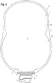
FIG. 3 is a front view of an exemplary pouch having the ostomy valve mounted thereto; -
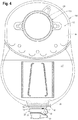
FIG. 4 is a rear view of another exemplary pouch having the ostomy valve mounted thereto; -
FIG. 5 is an enlarged rear view of the pouch and valve illustrated inFIG. 3 ; -
FIG. 6 is a view of the pouch and valve ofFIG. 5 shown with the cap removed; -
FIG. 7 is a view of the pouch and valve ofFIG. 6 with a discharge tube being connected to a stem portion of the valve; -
FIG. 8 is a view of the pouch and valve ofFIGS. 6 and7 with the discharge tube connected to the valve stem; -
FIG. 9 is a view similar toFIG. 8 with the valve rotated to the open position; -
FIG. 10 is a top view of the valve; -
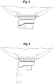
FIG. 10A is a cross-sectional illustration taken alongline 10A-10A ofFIG. 10 , the valve shown in the closed position; -
FIG. 10B is a cross-sectional illustration similar toFIG. 10A with the valve shown in the open position; -
FIG. 11 is a perspective view of an alternate embodiment of a valve for an ostomy pouch having tactile indication of valve position; -
FIG. 11A is a sectional view taken alongline 11A-11A ofFIG. 11 ; -
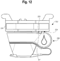
FIG. 12 is a front view of an alternative embodiment of the valve shown, the valve being shown in the closed position; -
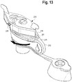
FIG. 13 is a top perspective view of the valve ofFIG. 12 ; -
FIG. 14 is a top view of the valve ofFIG. 12 shown intermediate the open and closed positions; -
FIG. 15 is a bottom view of the valve in the position ofFIG. 14 ; -
FIG. 16 is a bottom view of the valve, similar to that ofFIG. 15 and showing the rotation of the valve grasping portion toward the closed position; -
FIG. 16A is a sectional view taken alongline 16A--16A ofFIG. 16 ; -
FIG. 17 is a bottom view of the valve similar to that ofFIG. 16 , showing the cooperation of the detent components in shadowed lines; and -
FIG. 17A is a sectional view taken alongline 17A--17A ofFIG. 17 . - While the present disclosure is susceptible of embodiment in various forms, there is shown in the drawings and will hereinafter be described a presently preferred embodiment with the understanding that the present disclosure is to be considered an exemplification of the disclosure and is not intended to limit the disclosure to the specific embodiment illustrated.
- It should be further understood that the title of this section of this specification, namely, "Detailed Description", does not imply, nor should be inferred to limit the subject matter disclosed herein.
- Referring now to the figures and briefly first to
FIG. 3 , there is shown aurostomy pouch 10 having abody 12 formed by, for example, sealing twofilms 14a,b to one another about theirrespective peripheries 16 to define aninterior storage region 17. The bottom 18 of thepouch 10 includes anopening 20 into which avalve 22 is fitted and secured. Thefilms 14a,b can be sealed to one another by methods such a heat sealing and the like; thevalve 22 being similarly sealed to thepouch 10 at thebottom opening 20. Suitable methods for sealing the pouch walls/films 14 to one another andvalve 22 to the pouch films 14 will be recognized by those skilled in the art. - For purposes of the present disclosure and discussion, reference to "bottom," is intended to refer to the lower portion of the
pouch 10 and/orvalve 22 when thepouch 10 is adhered to a user's body. - As seen in
FIG. 4 , which shows analternate pouch 110, thepouch 110 also includes aninput opening 124 through which waste is input to thepouch 110 from a stoma. Theinput opening 124 is adhered to the user by a barrier (not shown) in a one-piece or two-piece configuration (the two-piece configuration being shown generally at 126, inFIG. 4 ), which configurations will also be recognized by those skilled in the art. - The
valve 22 is attached and sealed to thepouch bottom 18. Accordingly, thevalve 22 includes abody 28 that is sealed to thepouch films 14a,b and astem portion 30 that is supported in and by thebody 28. Thestem portion 30 is movable, e.g., rotatable, to open and close the valve 22 (e.g., to permit and isolate flow from the pouch 10). - The
valve body 28 is of a known design and, as seen inFIG. 1 , has a generally elongated honeycomb shape having diverging/converging ends 32 and an elongatedcentral portion 34. Referring toFIGS 10-10B , a cylindrical wall 36 defines a stem receiver or receiving region, which wall 36 is partially open as indicated at 38, and as described below. The wall 36 extends through thecentral portion 34 of thebody 28. The illustratedbody 28 has angular intersections, indicated generally at 40 inFIG. 1 , of the various sides (e.g.,central portion 34 with diverging/converging ends 32); however, it will be appreciated by those skilled in the art that the intersections can be rounded as well, and that such configurations are within the scope of the present disclosure. - The sides of the
valve 22, as indicated at 42, can be formed having multiple sealing surfaces orribs 44, as seen inFIG. 1 , or as seen inFIG. 10 , can define contiguous planar sealing surfaces 144. The sealing surfaces 44, 144 (whether contiguous or multiple) are configured to provide a region at which thepouch walls 14a,b are sealed to thevalve body 28 to effect a seal of thepouch 10 at the lower orbottom end 18. - The
valve body 28 includes a well 46, between theside walls 42 and further defined by abottom wall 48 and the partially open cylindrical wall or stem receiver 36. In apresent valve 22, the cylindrical wall 36 serves as a seat such that fluid can pass through thevalve body 28 and into thestem portion 30; that is fluid can pass from the well 46 through theopening 38. - The
stem portion 30 is positioned for rotation in the stem receiver 36. Thestem portion 30 is a hollow tubular member that includes acentral bore 50 and anopening 52 in a part of theside wall 54 that, when thevalve 22 is in the open position, is aligned with thestem receiver opening 38. In this manner a flow path is provided, as indicated at 56 inFIG. 10B , from thepouch 10, into the valve body well 46, through the alignedopenings stem receiver opening 38 and stemopening 52 are not aligned. (as seen inFIG. 10A ), that is, when thestem portion 30 is rotated 180°, the valve is in the closed position and flow through thevalve 22 is stopped. It will be appreciated that theopenings stem portion 30, and not just when the stem portion is rotated 180°. Accordingly, rotation of thestem portion 30 can be used to regulate or control flow through the valve at rotations up to and including 180°. - An
upper end 58 of thestem portion 30 includes an enlarged head portion orknob 60 that fits into an opening 62 in anupper portion 64 of thevalve body 28 to secure thestem portion 30 in place in thevalve body 28. Thehead 60 can be formed with a split configuration, as indicated at 66, to allow a snap-fit of thestem head 60 in the body upper opening 62. - The
stem portion 30 includes a graspingregion 68 to permit manually rotating thestem portion 30 between the open and closed positions. The graspingregion 68 is formed as a two-part member, thefirst part 70 being a frame or carrier that defines an outer bound 72 of the graspingregion 68 and is formed integral with the stem cylindrical wall or tubular portion 36. Thesecond part 74 is a tactile element that is disposed within theframe 70. Thetactile element 74 has a different "feel" from theframe portion 70. In apresent valve 22, thetactile portion 74 is formed from a material that is softer (e.g., a material having a lower durometer or surface hardness as compared to the material making up the first part 70) and has a higher frictional coefficient than theframe portion 70. It will be appreciated that this higher frictional coefficient provides a no-slip or lesser slip surface than theframe portion 70 for a more positive hold on thestem grasping region 68. - The grasping
region 68 also has anenlarged end portion 76. Theenlarged end 76 provides a larger area by which a user can grasp and manually manipulate (e.g., rotate) thestem portion 30 to open and close thevalve 22. The valve further includes a stop to prevent over-rotation of thevalve 30. In a present valve, the stop is formed by a dependingstub 77 on thevalve body 28 moves into arecess 79 in the graspingportion 68. Thestub 77 engages therecess 79 to stop rotation of thestem portion 30. - One side 78 of the
end 76 includes anindicator 80 that is sensed by touch (that is, also tactile), so that a user can determine from touch only, the state or position of thevalve 22. In apresent valve 22, theindicator 80 is a raisedelement 82 in the shape of a drop or tear-drop that is formed on one side 78 of theend 76; theother side 84 of theend 76 is devoid of the tactile indicator 80 (the raised drop formation 82). Thedrop formation 82 may be formed as part of and from the same material as theframe 70. In this manner, thedrop 82 has a raised surface, raised above thetactile portion 74, and is of a different material than the surroundingtactile portion 74 or frictional surface to provide positive tactile indication of thevalve 22 position. Referring briefly toFIG. 2 , the graspingregion 68, which is an open molded part, includesdrainage openings 69 in abottom surface 71 to permit the drainage of fluid, such therefrom, for example, following a shower during which water may enter the graspingportion 68. - In a
present valve 22, thestem portion 30 is molded from a relatively rigid material that when molded and cured or hardened has a relatively smooth finish. One such material is a plastic or polymeric material such as a high density polyethylene (HDPE). The material can include a slip agent formulated with the HDPE to provide smooth manipulation or rotation of thestem portion 30 within thebody 28; that is smooth, unfettered movement of thestem portion 30 between the open and closed position. - In a
present valve 22, thestem portion 30 is molded as a unitary member, that is molded with the graspingportion frame 70 formed integral with the hollow tubular portion 36. In this configuration, the graspingportion 68 is molded as part of theframe 70, with a bounding wall oredge 72 and a recessedarea 86 within the boundingwall 72, and the raiseddrop formation 82, is also formed as part of and supported by theframe 70. - The higher friction
tactile element 74 is positioned within the recessedarea 86 in the graspingregion 68. In apresent valve 22, the higher frictiontactile element 74 is molded into the recessedarea 86, such as in an overmold process, between the boundingwalls 72 and around the raisedelement 82. - In a
present valve 22, the higher frictiontactile element 74 may be formed from a thermoplastic elastomer (TPE) such as that available from PolyOne Corp. under the trade name DYNAFLEX®. A current material includes TPE that has a polypropylene resin added at a weigh percent of about 10 percent to the material composition. - Referring to
FIG. 6 , thestem portion 30, below the graspingregion 68 includes abarb element 88 on the tubular portion 36. Thebarb element 88 is adapted to permit connecting a discharge tube or otherfluid conduit 90 onto theend 92 of thestem portion 30 and to temporarily secure thetube 90 to thestem portion 30. - The
valve 22 further includes a cap orclosure 94 that is configured to close off thestem end 92. Thecap 94 can be formed from a material similar to the grasping region insert 74 (the TPE material) which is sufficiently soft and pliable to allow a user to readily and comfortably position thecap 94 on thestem end 92. Thecap 94 can include aninner plug 95 that fits into stem end 92 or rests abutting theend 92 to provide a more secure seal of thevalve 22. Apresent cap 94 includes aring member 96 that fits over thetubular stem end 92 with atether 98 to secure thecap 94 to thevalve 22. Thering member 96 is configured to be positioned between thebarb element 88 and the graspingregion 68 to prevent interfering with attachment of thedischarge tube 90 to thestem portion 30. - It will be appreciated that when the
pouch 10 is worn during the day, thevalve 22 will like be closed, and thepouch 10 emptied when it is convenient to the user. When a user is bedridden or during the nighttime, for example when sleeping, the user will likely connect the discharge tube orconduit 90 to thevalve 22, leaving thevalve 22 open, so that fluids can drain directly to a collection container, such as, for example, a night drainage bag (not shown). - To this end, as seen in
FIGS. 7-9 , the extension ordischarge tube 90 can be attached to the valve stemend 92. Thedischarge tube 90 includes aconnector portion 100 that fits over thestem end 92, and preferably secured to thebarb element 88 below the graspingportion 68. It will be understood that thedischarge connector portion 100 can be fitted on thestem end 92 when thecap 94 is removed. - The
connector portion 100 includesflexible arms 102 that each have aliving hinge 104. Oneend 106 of eacharm 102 terminates in an inwardly orientedfinger 108. Anopposing end 110 of thearm 102 is configured for a user to pinch thearm 102 so as to pivot thearm 102 about thehinge 104. In a resting state, thearms 102 are biased inwardly, toward thetube 90. Thus, when pinching thearms 102 toward one another (inward, toward the tube 90), thefingers 108 are urged outwardly. Thefingers 108 are positioned such that when thedischarge tube 90 is connected to thestem end 92, thefingers 108 are located above thebarb element 88 as illustrated inFIG. 8 . This prevents undesired pull-out of thedischarge tube 90 from thestem portion 30. - In a
present discharge tube 90, theconnector portion 100 is configured such that theconnector portion 100 anddischarge tube 90 can freely rotate about thestem end 92, without twisting thevalve 22. That is, there is sufficient tolerance between theconnector portion 100, in conjunction with thestem portion 30 material, to allow thedischarge tube 90 to rotate. In this manner, there less opportunity for thetube 90 orpouch 10 to become twisted or pinched if, for example, the user rolls over while resting, which could otherwise reduce or stop flow from thepouch 10. The connection is, however, liquid-tight, to prevent leakage. - It will be appreciated by those skilled in the art that there are many benefits and advantages of the
present valve 22. For example, thevalve 22 provides both tactile and visual indication of thevalve 22 position. In low to no-light conditions, of for users that may have difficultly seeing thevalve 22, tactile indication of the valve position will be just one readily and greatly appreciated advantage. Moreover, thesofter overmold portion 74 provides a user with a secure grip on thevalve grasping region 68 to facilitate readily opening or closing thevalve 22. In addition, thevalve 22 design, including the tetheredcap 94 , has an overall pleasing aesthetic, which may be appreciated by some users. - Moreover, the discharge
tube connector portion 100, which provides for free rotation about the valve stemend 92, will be understood to reduce the opportunity to twist or pinch thepouch 10 ordischarge tube 90, thus providing a higher level of confidence of continued flow when thevalve 22 is maintained in the open position. - In an alternate configuration of the
valve 222, as seen inFIGS. 12-17A , adetent 224 provides positive positioning of thevalve 22 in the full open and full closed positions. In this embodiment, aprojection 226 extends downwardly from thevalve body 228 that cooperates with aprojection 229 on the graspingportion 268 to indicate the fully closed position (FIG. 12 ) and cooperates with anend 231 of the graspingportion 268 to indicate the fully open (FIG. 13 ) position. - Referring to
FIGS. 15-16A , the dependingbody projection 226 can be formed as part of thevalve body 228. Theprojection 226 has an arcuate or inwardly curved shape or concavity, that definecontact edges 233a,b and acentral receiving region 235, in the direction of the valve stem 230. Theprojection 226 is formed as a hollow element that permits readily and easily moving the mating portions (e.g., the graspingportion projection 229 and end 231) into and out of contact with thebody projection 226. The hollow interior (as indicated at 237) provides a soft and resilient abutment with which the graspingportion 268 cooperates. - As described above, the grasping portion projection is formed on an
upper rim 239 that is defined in part by aslot 241 in therim 239. Theprojection grasping portion 229 has a complementary arcuate or outwardly curved shape or convexity, that mates and cooperates with the concavity in thebody projection 226. As the graspingportion 268 is rotated toward the closed position (as indicated by the arrow at 243 inFIG. 16 ), the graspingportion projection 229 moves into contact with thebody projection 226 and encounters a slight resistance as it contacts one of therespective edges 233a,b. Continued rotation of the graspingportion 268 overcomes the slight resistance and moves the graspingportion projection 229 beyond theedge 233a or b, into the concavity or receivingregion 235 on thebody projection 226. Fully mating the twoprojections valve 222 is in the fully closed position, as there is a slight resistance to move the graspingportion 268 beyond the fully closed position. - From the fully closed position, continued rotation of the grasping portion 268 (which unmates the
projections 229 and 226) moves thevalve 222 into an intermediate position in which thevalve 222 is partially open. Further rotation moves thevalve 222 toward the fully open position as illustrated inFIG. 13 . In this position, the graspingportion end 231 contacts and cooperates with thevalve body projection 226 in much the same manner as graspingportion projection 229. That is, as the graspingportion 268 is rotated toward the open position (the open position being shown inFIG. 13 ), the graspingportion end 231 moves into contact with thebody projection 226 and encounters a slight resistance as it contacts one of therespective edges 233a,b. Continued rotation of the graspingportion 268 overcomes the slight resistance and moves the graspingportion end 231 convexity into the concavity or receivingregion 235 on thebody projection 226. Fully mating the graspingportion end 231 convexity and thebody projection 226 concavity or receivingregion 235, provides tactile indication that thevalve 222 is in the full open position, as there is a slight resistance to move the graspingportion 268 beyond the fully open position. - In the present disclosure, the words "a" or "an" are to be taken to include both the singular and the plural. Conversely, any reference to plural items shall, where appropriate, include the singular.
- From the foregoing it will be observed that numerous modifications and variations can be effectuated without departing from the scope of the novel concepts of the present disclosure. It is to be understood that no limitation with respect to the specific embodiments illustrated is intended or should be inferred. The disclosure is intended to cover by the appended claims all such modifications as fall within the scope of the claims.
Claims (14)
- A valve that is sealable to an associated container for collecting bodily fluid having an interior, the valve adapted to permit and stop flow of fluid from the container interior, the valve comprising:a valve body (28) sealable to the container, the valve body (28) having a stem receiver formed therein, the valve body (28) including a fluid receiving region in communication with the container interior;a stem (30) mounted to the valve body (28), the stem (30) having a hollow central portion, a sealed upper portion and an opposite stem end (92), the stem positioned in the stem receiving region and adapted for rotation within the stem receiving region, the stem including a stem opening in a portion of a wall (36) thereof, the stem (30) being rotatable between an open position to align the stem opening with the valve body fluid receiving region to permit flow from the fluid storage region through the valve, and a closed position to misalign the stem opening with the valve body fluid receiving region to stop flow through the valve,the stem (30) having a grasping region (68) spaced from the valve body (28), the grasping region (68) adapted rotate the stem(30) within the stem receiving region to move the valve between the open and closed positions, the grasping region (68) including a tactile indicator (80) to provide indication of the valve position,characterized in thatthe tactile indicator (80) is a raised portion (82) on a side surface of the grasping region (68), an opposite side surface of the grasping region (68) being devoid of a raised region,and wherein the hollow central portion (50) of the stem (30) provides a flow path, wherein bodily fluid flows through the fluid receiving region in the valve body (28), through the stem opening, and out through the hollow central portion (50) and the end (92) of the stem (82) when the valve is in the open position.
- The valve of claim 1 including an insert portion formed on the grasping region (68), the insert portion being formed from a material that is different from a material of the stem portion.
- The valve of claim 2 wherein the insert portion has a higher frictional coefficient than the stem portion.
- The valve of any of claims 1-3 wherein the raised portion (82) is formed having a drop-like shape.
- The valve of any of claims 2-4, wherein the raised portion (82) is formed as part of, and integral with, the stem portion (30), and wherein the insert portion surrounds, at least in part, the raised portion (82).
- The valve of any of claims 1-5 including a detent to provide indication of the valve in one or both of the open and closed positions.
- An ostomy pouch, comprising:a pouch having first and second walls (14a, b) sealed to one another at about their respective peripheries defining an interior fluid storage region, an inlet and an outlet; anda valve (22) according to any of claims 1-6.
- The ostomy pouch of claim 7 including an insert portion formed on both the first and second sides of the grasping portion (68), the insert portion formed from a material that is different from a material of the stem.
- The ostomy pouch of claim 8 wherein the grasping portion (68) is formed as a frame in which the insert portion is disposed and wherein the tactile indicator is a raised portion formed integral with the frame.
- The ostomy pouch of claim 9 wherein the insert portion is formed from a soft material having a higher frictional coefficient than the stem material.
- The ostomy pouch of claim 10 wherein the insert portion is formed from a thermoplastic elastomer.
- The ostomy pouch of any of claims 7-11 wherein the grasping region (68) includes drainage openings in a bottom surface thereof.
- The ostomy pouch of any of claims 7-12 wherein the valve includes a detent to provide indication of the valve in one or both of the open and closed positions.
- The ostomy pouch of any of claims 7-13 wherein the valve includes a stop to stop rotation of the valve stem beyond the fully closed position.
Applications Claiming Priority (3)
| Application Number | Priority Date | Filing Date | Title |
|---|---|---|---|
| US41607210P | 2010-11-22 | 2010-11-22 | |
| US13/301,395 US8882732B2 (en) | 2010-11-22 | 2011-11-21 | Valve for ostomy pouch |
| PCT/US2011/061833 WO2012071406A1 (en) | 2010-11-22 | 2011-11-22 | Valve for ostomy pouch |
Publications (2)
| Publication Number | Publication Date |
|---|---|
| EP2642956A1 EP2642956A1 (en) | 2013-10-02 |
| EP2642956B1 true EP2642956B1 (en) | 2017-07-12 |
Family
ID=46065014
Family Applications (1)
| Application Number | Title | Priority Date | Filing Date |
|---|---|---|---|
| EP11791404.4A Active EP2642956B1 (en) | 2010-11-22 | 2011-11-22 | Valve for ostomy pouch |
Country Status (8)
| Country | Link |
|---|---|
| US (2) | US8882732B2 (en) |
| EP (1) | EP2642956B1 (en) |
| JP (1) | JP5498627B2 (en) |
| AU (1) | AU2011331943B2 (en) |
| CA (1) | CA2811099C (en) |
| DK (1) | DK2642956T3 (en) |
| HU (1) | HUE034678T2 (en) |
| WO (1) | WO2012071406A1 (en) |
Cited By (5)
| Publication number | Priority date | Publication date | Assignee | Title |
|---|---|---|---|---|
| USD978345S1 (en) | 2022-10-26 | 2023-02-14 | Gv Solutions Llc | Drain assembly for an ostomy bag |
| US11701249B2 (en) | 2021-10-29 | 2023-07-18 | Gv Solutions Llc | Drain asembly for elimination of urine waste from an ostomy bag |
| US11951028B2 (en) | 2021-10-29 | 2024-04-09 | Gv Solutions Llc | Method for assembling a drain assembly and method for elimination of urine waste from an ostomy bag |
| US12290657B1 (en) | 2023-12-14 | 2025-05-06 | Gv Solutions Llc | Adaptable connector for urostomy bags |
| USD1100190S1 (en) | 2024-12-13 | 2025-10-28 | Gv Solutions Llc | Urostomy bag connector |
Families Citing this family (34)
| Publication number | Priority date | Publication date | Assignee | Title |
|---|---|---|---|---|
| USD671620S1 (en) * | 2010-11-22 | 2012-11-27 | Hollister Incorporated | Valve with tactile position indication |
| US8882732B2 (en) * | 2010-11-22 | 2014-11-11 | Hollister Incorporated | Valve for ostomy pouch |
| US9107737B2 (en) * | 2011-11-21 | 2015-08-18 | Alan Schwartz | Goggles with facial conforming eyepieces |
| USD754848S1 (en) * | 2012-03-22 | 2016-04-26 | Hollister Incorporated | Expandable ostomy appliance |
| US10406344B2 (en) * | 2012-09-11 | 2019-09-10 | Becton Dickinson and Company Limited | Adapter cap for drug transfer assembly |
| US20150051563A1 (en) * | 2013-08-14 | 2015-02-19 | Dale Martin Frimel | Ostomy stoma waste overflow system |
| US20150119836A1 (en) * | 2013-10-29 | 2015-04-30 | Dale Martin Frimel | Ostomy stoma waste overflow process and bag |
| EP2891475B1 (en) | 2014-01-03 | 2017-09-20 | Hollister Incorporated | Lubricated valve for ostomy pouch |
| US10251770B2 (en) * | 2014-01-03 | 2019-04-09 | Hollister Incorporated | Lubricated valve for ostomy pouch |
| EP3169621B1 (en) * | 2014-07-16 | 2021-09-08 | Coloplast A/S | Outlet for a urostomy appliance |
| US11000400B2 (en) * | 2016-02-05 | 2021-05-11 | Hollister Incorporated | Retractable outlet for ostomy pouch |
| HUE063862T2 (en) * | 2016-06-29 | 2024-02-28 | Hollister Inc | Urinary catheter with sealed chamber |
| LT3544554T (en) * | 2016-11-22 | 2024-05-10 | Hollister Incorporated | Drainage system for ostomy pouch |
| AU2019268260B2 (en) * | 2018-05-17 | 2024-07-11 | Hollister Incorporated | Ostomy collection and drainage system |
| US12060258B2 (en) | 2018-09-27 | 2024-08-13 | Global Life Sciences Solutions Usa Llc | System, method and apparatus for minimizing dead legs in a bioreactor system |
| US11040867B2 (en) * | 2018-09-27 | 2021-06-22 | Global Life Sciences Solutions Usa Llc | System, method and apparatus for minimizing dead legs in a bioreactor system |
| GB201820596D0 (en) * | 2018-12-18 | 2019-01-30 | Salts Healthcare Ltd | A valve for a urostomy appliance |
| GB2581832B (en) * | 2019-02-28 | 2023-01-25 | Salts Healthcare Ltd | A valve for a urostomy appliance |
| USD910170S1 (en) | 2019-04-19 | 2021-02-09 | Hollister Incorporated | Ostomy pouch outlet |
| USD905852S1 (en) | 2019-07-23 | 2020-12-22 | Hollister Incorporated | Drainage bag outlet including closure |
| US11590016B1 (en) | 2020-01-28 | 2023-02-28 | Kayal Medical Products LLC | Ostomy system |
| HUE063281T2 (en) * | 2020-02-19 | 2024-01-28 | Convatec Ltd | An outlet valve for an ostomy appliance |
| US20210251795A1 (en) * | 2020-02-19 | 2021-08-19 | Convatec Limited | Outlet valve for an ostomy appliance |
| GB202008258D0 (en) * | 2020-06-02 | 2020-07-15 | Convatec Ltd | An ostomy pounch |
| WO2022135644A1 (en) * | 2020-12-22 | 2022-06-30 | Coloplast A/S | A valve for a urostomy appliance |
| EP4267050B1 (en) * | 2020-12-22 | 2026-02-11 | Coloplast A/S | A valve for a urostomy appliance |
| US20230075150A1 (en) * | 2021-09-08 | 2023-03-09 | Brian Smith | Urostomy Drain Tube Device |
| GB2612627A (en) * | 2021-11-05 | 2023-05-10 | Salts Healthcare Ltd | A valve for a urostomy appliance |
| GB2612625A (en) * | 2021-11-05 | 2023-05-10 | Salts Healthcare Ltd | A valve for urostomy appliance |
| GB2612626A (en) * | 2021-11-05 | 2023-05-10 | Salts Healthcare Ltd | A valve for a urostomy appliance |
| GB2615826A (en) * | 2022-02-22 | 2023-08-23 | Salts Healthcare Ltd | An ostomy drainage system |
| GB2621357A (en) * | 2022-08-09 | 2024-02-14 | Salts Healthcare Ltd | An ostomy drainage system |
| GB2622098A (en) * | 2022-09-05 | 2024-03-06 | Salts Healthcare Ltd | A drainage assembly |
| JP7539197B1 (en) | 2024-06-13 | 2024-08-23 | 北斗制御株式会社 | Artificial bladder device |
Citations (1)
| Publication number | Priority date | Publication date | Assignee | Title |
|---|---|---|---|---|
| GB2202032A (en) * | 1987-03-09 | 1988-09-14 | Craig Med Prod Ltd | Tap for drainage bag |
Family Cites Families (36)
| Publication number | Priority date | Publication date | Assignee | Title |
|---|---|---|---|---|
| US3481336A (en) * | 1967-05-15 | 1969-12-02 | Levoy Inc S | Body waste receptor appliance |
| US4055179A (en) * | 1975-03-31 | 1977-10-25 | Plastronics, Inc. | Valve for urinary drainage container or similar article |
| US4147184A (en) * | 1975-04-30 | 1979-04-03 | Baxter Travenol Laboratories, Inc. | Adjustable valve |
| US4238059A (en) | 1977-11-29 | 1980-12-09 | Howmedica, Inc. | Stoma drainage appliance |
| SE443708B (en) * | 1979-08-06 | 1986-03-10 | Kingsdown Medical Consultants | TAPE VALVE FOR AN UROSTOMY PHASE |
| US4280498A (en) * | 1979-10-22 | 1981-07-28 | Hollister Incorporated | Valved drain assembly for urostomy pouch |
| US4443219A (en) * | 1981-03-10 | 1984-04-17 | C. R. Bard, Inc. | System for aseptically draining a urine bag |
| US4592750A (en) * | 1984-10-26 | 1986-06-03 | Kay Dennis M | Ostomy appliance |
| DK158319C (en) * | 1984-11-26 | 1990-11-12 | Asicomo As | VALVE, ISAIR FOR SINGLE USE |
| USD295220S (en) * | 1985-02-12 | 1988-04-12 | Kay Dennis M | Drain valve for ostomy receptacles |
| US4668227A (en) * | 1985-05-08 | 1987-05-26 | Kay Dennis M | Stoma hygiene system and process therefor |
| DK154268C (en) * | 1985-09-27 | 1989-04-03 | Coloplast As | BAG OF PLASTIC WRAP FOR COLLECTION OF BODY OR WAVE-shaped WRAPPING PATTERNS, CATHERS OR OTHER PIPE OR HOSE-SHAPED BODIES |
| USD303575S (en) * | 1986-07-17 | 1989-09-19 | E. R. Squibb & Sons, Inc. | Wound drainage bag |
| US5226564A (en) * | 1986-11-28 | 1993-07-13 | E. R. Squibb & Sons, Inc. | Manufacture of bags |
| USD303574S (en) * | 1987-01-07 | 1989-09-19 | E. R. Squibb & Sons, Inc. | Wound drainage bag |
| US5299777A (en) * | 1993-03-19 | 1994-04-05 | Milstead Brown W | Valved drain plug apparatus |
| US5658266A (en) * | 1993-08-02 | 1997-08-19 | Colacello; Albert A. | Manual venting and cutting apparatus for ostomy pouches |
| US5771590A (en) * | 1993-08-02 | 1998-06-30 | Colacello; Albert A. | Manual venting and cutting apparatus for ostomy pouches |
| US5401264A (en) * | 1994-04-18 | 1995-03-28 | Hollister Incorporated | Ostomy pouch with internal squeeze-to-open vent valve |
| US5443453A (en) | 1994-04-21 | 1995-08-22 | Sherwood Medical Company | Stop-cock valve |
| GB9408567D0 (en) | 1994-04-29 | 1994-06-22 | Mediquest Products Ltd | A valve for urine drainage applications |
| DK171757B1 (en) * | 1994-12-23 | 1997-05-12 | Coloplast As | Collection bag for human body secretions, especially for ostomy patients, collection bag system comprising such bag and bag attachment for such system |
| USD396731S (en) * | 1996-04-04 | 1998-08-04 | Mirto Clorinda M | Urostomy bag drainage valve |
| US6132407A (en) * | 1997-02-06 | 2000-10-17 | C. R. Bard, Inc. | Outlet tube device for urinary drainage bag |
| US5968024A (en) * | 1998-02-24 | 1999-10-19 | E. R. Squibb & Sons, Inc. | Ostomy appliance and wound drainage device with self adhering drain system |
| US7087041B2 (en) * | 1998-02-25 | 2006-08-08 | Zassi Medical Evolutions, Inc. | Pad for use with continent ostomy port |
| US6485476B1 (en) * | 1998-02-25 | 2002-11-26 | Zassi Medical Evolutions, Inc. | Continent ostomy port |
| GB9809156D0 (en) | 1998-04-29 | 1998-07-01 | Bristol Myers Squibb Co | Tap |
| GB9904527D0 (en) * | 1999-02-26 | 1999-04-21 | Bristol Myers Squibb Co | Ostomy appliance |
| US7008407B1 (en) * | 2002-09-23 | 2006-03-07 | Owens-Illinois Closure Inc. | Urine collection method and apparatus |
| ES2569208T3 (en) * | 2004-09-03 | 2016-05-09 | Elcam Medical Agricultural Cooperative Association Ltd. | Stopcock |
| US7947025B2 (en) * | 2005-08-04 | 2011-05-24 | Convatec Technologies Inc. | Pouch for collecting human body waste and drainage adapter therefor |
| CN101453966B (en) * | 2006-05-24 | 2012-11-07 | 科洛普拉斯特公司 | A kit for collecting stool |
| CA2786339C (en) * | 2010-01-29 | 2017-07-11 | Mbh-International A/S | A drainage valve and a collection bag assembly comprising said valve |
| US8882732B2 (en) * | 2010-11-22 | 2014-11-11 | Hollister Incorporated | Valve for ostomy pouch |
| USD671620S1 (en) * | 2010-11-22 | 2012-11-27 | Hollister Incorporated | Valve with tactile position indication |
-
2011
- 2011-11-21 US US13/301,395 patent/US8882732B2/en active Active
- 2011-11-22 HU HUE11791404A patent/HUE034678T2/en unknown
- 2011-11-22 CA CA2811099A patent/CA2811099C/en active Active
- 2011-11-22 WO PCT/US2011/061833 patent/WO2012071406A1/en not_active Ceased
- 2011-11-22 DK DK11791404.4T patent/DK2642956T3/en active
- 2011-11-22 AU AU2011331943A patent/AU2011331943B2/en active Active
- 2011-11-22 JP JP2013541019A patent/JP5498627B2/en active Active
- 2011-11-22 EP EP11791404.4A patent/EP2642956B1/en active Active
-
2014
- 2014-09-16 US US14/487,713 patent/US9333110B2/en active Active
Patent Citations (1)
| Publication number | Priority date | Publication date | Assignee | Title |
|---|---|---|---|---|
| GB2202032A (en) * | 1987-03-09 | 1988-09-14 | Craig Med Prod Ltd | Tap for drainage bag |
Cited By (7)
| Publication number | Priority date | Publication date | Assignee | Title |
|---|---|---|---|---|
| US11701249B2 (en) | 2021-10-29 | 2023-07-18 | Gv Solutions Llc | Drain asembly for elimination of urine waste from an ostomy bag |
| US11951028B2 (en) | 2021-10-29 | 2024-04-09 | Gv Solutions Llc | Method for assembling a drain assembly and method for elimination of urine waste from an ostomy bag |
| US12350188B2 (en) | 2021-10-29 | 2025-07-08 | Solutions Llc | Drain asembly for elimination of urine waste from an ostomy bag |
| USD978345S1 (en) | 2022-10-26 | 2023-02-14 | Gv Solutions Llc | Drain assembly for an ostomy bag |
| US12290657B1 (en) | 2023-12-14 | 2025-05-06 | Gv Solutions Llc | Adaptable connector for urostomy bags |
| US12343494B1 (en) | 2023-12-14 | 2025-07-01 | Gv Solutions Llc | Adaptable connector for urostomy bags |
| USD1100190S1 (en) | 2024-12-13 | 2025-10-28 | Gv Solutions Llc | Urostomy bag connector |
Also Published As
| Publication number | Publication date |
|---|---|
| CA2811099C (en) | 2017-02-28 |
| HUE034678T2 (en) | 2018-02-28 |
| JP2013543788A (en) | 2013-12-09 |
| AU2011331943A1 (en) | 2013-04-11 |
| US20150025483A1 (en) | 2015-01-22 |
| CA2811099A1 (en) | 2012-05-31 |
| AU2011331943B2 (en) | 2014-07-17 |
| DK2642956T3 (en) | 2017-10-30 |
| US9333110B2 (en) | 2016-05-10 |
| EP2642956A1 (en) | 2013-10-02 |
| WO2012071406A1 (en) | 2012-05-31 |
| US20120130329A1 (en) | 2012-05-24 |
| JP5498627B2 (en) | 2014-05-21 |
| US8882732B2 (en) | 2014-11-11 |
Similar Documents
| Publication | Publication Date | Title |
|---|---|---|
| US9333110B2 (en) | Valve for ostomy pouch | |
| CA2875085C (en) | Lubricated valve for ostomy pouch | |
| EP3544554B1 (en) | Drainage system for ostomy pouch | |
| EP3930644B1 (en) | A valve for a urostomy appliance | |
| EP4106692B1 (en) | An outlet valve for an ostomy appliance | |
| EP4106687B1 (en) | An outlet valve for an ostomy appliance | |
| US12336927B2 (en) | Outlet valve for an ostomy appliance | |
| US20240245542A1 (en) | Drain asembly for elimination of urine waste from an ostomy bag | |
| JP2024537506A (en) | Drainage assembly for drainage of urinary waste from an ostomy bag | |
| WO2021165675A1 (en) | An outlet valve for an ostomy appliance | |
| US20080250554A1 (en) | Urinal | |
| DK2891475T3 (en) | Lubricated valve for ostomy bag | |
| EP2891475B1 (en) | Lubricated valve for ostomy pouch | |
| KR101735376B1 (en) | Portable urine disposal device |
Legal Events
| Date | Code | Title | Description |
|---|---|---|---|
| PUAI | Public reference made under article 153(3) epc to a published international application that has entered the european phase |
Free format text: ORIGINAL CODE: 0009012 |
|
| 17P | Request for examination filed |
Effective date: 20130612 |
|
| AK | Designated contracting states |
Kind code of ref document: A1 Designated state(s): AL AT BE BG CH CY CZ DE DK EE ES FI FR GB GR HR HU IE IS IT LI LT LU LV MC MK MT NL NO PL PT RO RS SE SI SK SM TR |
|
| DAX | Request for extension of the european patent (deleted) | ||
| 17Q | First examination report despatched |
Effective date: 20150424 |
|
| RIC1 | Information provided on ipc code assigned before grant |
Ipc: A61F 5/44 20060101AFI20161207BHEP Ipc: A61F 5/445 20060101ALI20161207BHEP Ipc: F16K 3/24 20060101ALI20161207BHEP |
|
| GRAP | Despatch of communication of intention to grant a patent |
Free format text: ORIGINAL CODE: EPIDOSNIGR1 |
|
| INTG | Intention to grant announced |
Effective date: 20170124 |
|
| RIN1 | Information on inventor provided before grant (corrected) |
Inventor name: HANNAN, JOHN, F. Inventor name: MARCH, DANIEL Inventor name: KING, TERENCE Inventor name: GOCZKOWSKI, JAKUB |
|
| GRAS | Grant fee paid |
Free format text: ORIGINAL CODE: EPIDOSNIGR3 |
|
| GRAA | (expected) grant |
Free format text: ORIGINAL CODE: 0009210 |
|
| AK | Designated contracting states |
Kind code of ref document: B1 Designated state(s): AL AT BE BG CH CY CZ DE DK EE ES FI FR GB GR HR HU IE IS IT LI LT LU LV MC MK MT NL NO PL PT RO RS SE SI SK SM TR |
|
| REG | Reference to a national code |
Ref country code: GB Ref legal event code: FG4D |
|
| REG | Reference to a national code |
Ref country code: CH Ref legal event code: EP |
|
| REG | Reference to a national code |
Ref country code: AT Ref legal event code: REF Ref document number: 907642 Country of ref document: AT Kind code of ref document: T Effective date: 20170715 |
|
| REG | Reference to a national code |
Ref country code: IE Ref legal event code: FG4D |
|
| REG | Reference to a national code |
Ref country code: DE Ref legal event code: R096 Ref document number: 602011039551 Country of ref document: DE |
|
| REG | Reference to a national code |
Ref country code: NL Ref legal event code: FP |
|
| REG | Reference to a national code |
Ref country code: DK Ref legal event code: T3 Effective date: 20171023 |
|
| REG | Reference to a national code |
Ref country code: LT Ref legal event code: MG4D Ref country code: FR Ref legal event code: PLFP Year of fee payment: 7 |
|
| REG | Reference to a national code |
Ref country code: AT Ref legal event code: MK05 Ref document number: 907642 Country of ref document: AT Kind code of ref document: T Effective date: 20170712 |
|
| PG25 | Lapsed in a contracting state [announced via postgrant information from national office to epo] |
Ref country code: AT Free format text: LAPSE BECAUSE OF FAILURE TO SUBMIT A TRANSLATION OF THE DESCRIPTION OR TO PAY THE FEE WITHIN THE PRESCRIBED TIME-LIMIT Effective date: 20170712 Ref country code: NO Free format text: LAPSE BECAUSE OF FAILURE TO SUBMIT A TRANSLATION OF THE DESCRIPTION OR TO PAY THE FEE WITHIN THE PRESCRIBED TIME-LIMIT Effective date: 20171012 Ref country code: FI Free format text: LAPSE BECAUSE OF FAILURE TO SUBMIT A TRANSLATION OF THE DESCRIPTION OR TO PAY THE FEE WITHIN THE PRESCRIBED TIME-LIMIT Effective date: 20170712 Ref country code: LT Free format text: LAPSE BECAUSE OF FAILURE TO SUBMIT A TRANSLATION OF THE DESCRIPTION OR TO PAY THE FEE WITHIN THE PRESCRIBED TIME-LIMIT Effective date: 20170712 Ref country code: HR Free format text: LAPSE BECAUSE OF FAILURE TO SUBMIT A TRANSLATION OF THE DESCRIPTION OR TO PAY THE FEE WITHIN THE PRESCRIBED TIME-LIMIT Effective date: 20170712 Ref country code: SE Free format text: LAPSE BECAUSE OF FAILURE TO SUBMIT A TRANSLATION OF THE DESCRIPTION OR TO PAY THE FEE WITHIN THE PRESCRIBED TIME-LIMIT Effective date: 20170712 |
|
| PG25 | Lapsed in a contracting state [announced via postgrant information from national office to epo] |
Ref country code: GR Free format text: LAPSE BECAUSE OF FAILURE TO SUBMIT A TRANSLATION OF THE DESCRIPTION OR TO PAY THE FEE WITHIN THE PRESCRIBED TIME-LIMIT Effective date: 20171013 Ref country code: PL Free format text: LAPSE BECAUSE OF FAILURE TO SUBMIT A TRANSLATION OF THE DESCRIPTION OR TO PAY THE FEE WITHIN THE PRESCRIBED TIME-LIMIT Effective date: 20170712 Ref country code: RS Free format text: LAPSE BECAUSE OF FAILURE TO SUBMIT A TRANSLATION OF THE DESCRIPTION OR TO PAY THE FEE WITHIN THE PRESCRIBED TIME-LIMIT Effective date: 20170712 Ref country code: IS Free format text: LAPSE BECAUSE OF FAILURE TO SUBMIT A TRANSLATION OF THE DESCRIPTION OR TO PAY THE FEE WITHIN THE PRESCRIBED TIME-LIMIT Effective date: 20171112 Ref country code: ES Free format text: LAPSE BECAUSE OF FAILURE TO SUBMIT A TRANSLATION OF THE DESCRIPTION OR TO PAY THE FEE WITHIN THE PRESCRIBED TIME-LIMIT Effective date: 20170712 Ref country code: LV Free format text: LAPSE BECAUSE OF FAILURE TO SUBMIT A TRANSLATION OF THE DESCRIPTION OR TO PAY THE FEE WITHIN THE PRESCRIBED TIME-LIMIT Effective date: 20170712 Ref country code: BG Free format text: LAPSE BECAUSE OF FAILURE TO SUBMIT A TRANSLATION OF THE DESCRIPTION OR TO PAY THE FEE WITHIN THE PRESCRIBED TIME-LIMIT Effective date: 20171012 |
|
| REG | Reference to a national code |
Ref country code: HU Ref legal event code: AG4A Ref document number: E034678 Country of ref document: HU |
|
| REG | Reference to a national code |
Ref country code: DE Ref legal event code: R097 Ref document number: 602011039551 Country of ref document: DE |
|
| PG25 | Lapsed in a contracting state [announced via postgrant information from national office to epo] |
Ref country code: RO Free format text: LAPSE BECAUSE OF FAILURE TO SUBMIT A TRANSLATION OF THE DESCRIPTION OR TO PAY THE FEE WITHIN THE PRESCRIBED TIME-LIMIT Effective date: 20170712 Ref country code: CZ Free format text: LAPSE BECAUSE OF FAILURE TO SUBMIT A TRANSLATION OF THE DESCRIPTION OR TO PAY THE FEE WITHIN THE PRESCRIBED TIME-LIMIT Effective date: 20170712 |
|
| PLBE | No opposition filed within time limit |
Free format text: ORIGINAL CODE: 0009261 |
|
| STAA | Information on the status of an ep patent application or granted ep patent |
Free format text: STATUS: NO OPPOSITION FILED WITHIN TIME LIMIT |
|
| PG25 | Lapsed in a contracting state [announced via postgrant information from national office to epo] |
Ref country code: IT Free format text: LAPSE BECAUSE OF FAILURE TO SUBMIT A TRANSLATION OF THE DESCRIPTION OR TO PAY THE FEE WITHIN THE PRESCRIBED TIME-LIMIT Effective date: 20170712 Ref country code: EE Free format text: LAPSE BECAUSE OF FAILURE TO SUBMIT A TRANSLATION OF THE DESCRIPTION OR TO PAY THE FEE WITHIN THE PRESCRIBED TIME-LIMIT Effective date: 20170712 Ref country code: SK Free format text: LAPSE BECAUSE OF FAILURE TO SUBMIT A TRANSLATION OF THE DESCRIPTION OR TO PAY THE FEE WITHIN THE PRESCRIBED TIME-LIMIT Effective date: 20170712 Ref country code: SM Free format text: LAPSE BECAUSE OF FAILURE TO SUBMIT A TRANSLATION OF THE DESCRIPTION OR TO PAY THE FEE WITHIN THE PRESCRIBED TIME-LIMIT Effective date: 20170712 |
|
| 26N | No opposition filed |
Effective date: 20180413 |
|
| PG25 | Lapsed in a contracting state [announced via postgrant information from national office to epo] |
Ref country code: MC Free format text: LAPSE BECAUSE OF FAILURE TO SUBMIT A TRANSLATION OF THE DESCRIPTION OR TO PAY THE FEE WITHIN THE PRESCRIBED TIME-LIMIT Effective date: 20170712 |
|
| PG25 | Lapsed in a contracting state [announced via postgrant information from national office to epo] |
Ref country code: LI Free format text: LAPSE BECAUSE OF NON-PAYMENT OF DUE FEES Effective date: 20171130 Ref country code: CH Free format text: LAPSE BECAUSE OF NON-PAYMENT OF DUE FEES Effective date: 20171130 |
|
| PG25 | Lapsed in a contracting state [announced via postgrant information from national office to epo] |
Ref country code: LU Free format text: LAPSE BECAUSE OF NON-PAYMENT OF DUE FEES Effective date: 20171122 Ref country code: SI Free format text: LAPSE BECAUSE OF FAILURE TO SUBMIT A TRANSLATION OF THE DESCRIPTION OR TO PAY THE FEE WITHIN THE PRESCRIBED TIME-LIMIT Effective date: 20170712 |
|
| REG | Reference to a national code |
Ref country code: BE Ref legal event code: MM Effective date: 20171130 |
|
| PG25 | Lapsed in a contracting state [announced via postgrant information from national office to epo] |
Ref country code: MT Free format text: LAPSE BECAUSE OF NON-PAYMENT OF DUE FEES Effective date: 20171122 |
|
| PG25 | Lapsed in a contracting state [announced via postgrant information from national office to epo] |
Ref country code: BE Free format text: LAPSE BECAUSE OF NON-PAYMENT OF DUE FEES Effective date: 20171130 |
|
| PG25 | Lapsed in a contracting state [announced via postgrant information from national office to epo] |
Ref country code: CY Free format text: LAPSE BECAUSE OF NON-PAYMENT OF DUE FEES Effective date: 20170712 |
|
| PG25 | Lapsed in a contracting state [announced via postgrant information from national office to epo] |
Ref country code: MK Free format text: LAPSE BECAUSE OF FAILURE TO SUBMIT A TRANSLATION OF THE DESCRIPTION OR TO PAY THE FEE WITHIN THE PRESCRIBED TIME-LIMIT Effective date: 20170712 |
|
| PG25 | Lapsed in a contracting state [announced via postgrant information from national office to epo] |
Ref country code: TR Free format text: LAPSE BECAUSE OF FAILURE TO SUBMIT A TRANSLATION OF THE DESCRIPTION OR TO PAY THE FEE WITHIN THE PRESCRIBED TIME-LIMIT Effective date: 20170712 |
|
| PG25 | Lapsed in a contracting state [announced via postgrant information from national office to epo] |
Ref country code: PT Free format text: LAPSE BECAUSE OF FAILURE TO SUBMIT A TRANSLATION OF THE DESCRIPTION OR TO PAY THE FEE WITHIN THE PRESCRIBED TIME-LIMIT Effective date: 20170712 |
|
| PG25 | Lapsed in a contracting state [announced via postgrant information from national office to epo] |
Ref country code: AL Free format text: LAPSE BECAUSE OF FAILURE TO SUBMIT A TRANSLATION OF THE DESCRIPTION OR TO PAY THE FEE WITHIN THE PRESCRIBED TIME-LIMIT Effective date: 20170712 |
|
| PGFP | Annual fee paid to national office [announced via postgrant information from national office to epo] |
Ref country code: NL Payment date: 20241126 Year of fee payment: 14 |
|
| PGFP | Annual fee paid to national office [announced via postgrant information from national office to epo] |
Ref country code: HU Payment date: 20241113 Year of fee payment: 14 |
|
| PGFP | Annual fee paid to national office [announced via postgrant information from national office to epo] |
Ref country code: DE Payment date: 20241127 Year of fee payment: 14 |
|
| PGFP | Annual fee paid to national office [announced via postgrant information from national office to epo] |
Ref country code: DK Payment date: 20241126 Year of fee payment: 14 |
|
| PGFP | Annual fee paid to national office [announced via postgrant information from national office to epo] |
Ref country code: GB Payment date: 20241127 Year of fee payment: 14 |
|
| PGFP | Annual fee paid to national office [announced via postgrant information from national office to epo] |
Ref country code: FR Payment date: 20241128 Year of fee payment: 14 |
|
| PGFP | Annual fee paid to national office [announced via postgrant information from national office to epo] |
Ref country code: IE Payment date: 20241127 Year of fee payment: 14 |