EP2642692A1 - Monitoring of a communication device over time - Google Patents
Monitoring of a communication device over time Download PDFInfo
- Publication number
- EP2642692A1 EP2642692A1 EP20120160397 EP12160397A EP2642692A1 EP 2642692 A1 EP2642692 A1 EP 2642692A1 EP 20120160397 EP20120160397 EP 20120160397 EP 12160397 A EP12160397 A EP 12160397A EP 2642692 A1 EP2642692 A1 EP 2642692A1
- Authority
- EP
- European Patent Office
- Prior art keywords
- rate
- message
- sequence
- messages
- events
- Prior art date
- Legal status (The legal status is an assumption and is not a legal conclusion. Google has not performed a legal analysis and makes no representation as to the accuracy of the status listed.)
- Granted
Links
Images




Classifications
-
- H—ELECTRICITY
- H04—ELECTRIC COMMUNICATION TECHNIQUE
- H04L—TRANSMISSION OF DIGITAL INFORMATION, e.g. TELEGRAPHIC COMMUNICATION
- H04L41/00—Arrangements for maintenance, administration or management of data switching networks, e.g. of packet switching networks
- H04L41/14—Network analysis or design
- H04L41/147—Network analysis or design for predicting network behaviour
-
- H—ELECTRICITY
- H04—ELECTRIC COMMUNICATION TECHNIQUE
- H04L—TRANSMISSION OF DIGITAL INFORMATION, e.g. TELEGRAPHIC COMMUNICATION
- H04L41/00—Arrangements for maintenance, administration or management of data switching networks, e.g. of packet switching networks
- H04L41/14—Network analysis or design
- H04L41/142—Network analysis or design using statistical or mathematical methods
Definitions
- the invention relates to the technical field of monitoring of communication devices, in particular communications networks and network elements thereof.
- Communications networks have grown more and more complex in terms of architecture and also in terms of implemented processes, protocols and services.
- the increasing complexity poses a challenge to network operators in charge of ensuring faultless operations.
- the invention provides a method for monitoring a communication device, comprising:
- the method can be implemented with a flow of incoming messages received by the communication device from its environment.
- the method can also be implemented with a flow of messages transmitted by the communication device to its environment.
- such a method can comprise one or more of the features below.
- the method further comprises detecting an abnormal state of the communication device as a function of the sequence of rate change events.
- the abnormal state is detected in response to a monotonous evolution of the modelized rate over a long period of time, which hints at a diverging behavior of the device.
- the abnormal state is detected as a function of a number of different modelized rates that have been obtained over time, e.g. when that number becomes higher than a given threshold, thus hinting at a long-term instability of the communications device.
- the computation of the modelized rate of the messages and subsequent detection of rate change events over time can be done with a number of mathematical models, e.g. by calculating a linear regression function of the message events over a sliding time window. More refined statistical correlations could be computed as well, although computational cost should generally be kept sufficiently low for a real time implementation of the method to be possible.
- the updating of the modelized rate comprises:
- the repeated steps further comprise:
- the updating of the time-window comprises:
- At least one of an earliest boundary and a latest boundary of the time-window is computed as a function of the rank of the subsequent message event in the sequence of message events divided by the current modelized rate.
- an earliest boundary of the time-window is computed as a function of a positive parameter representing a maximum number of messages of the flow that may arrive simultaneously at the communication device in a normal state of the communication device.
- a latest boundary of the time-window is computed as a function of a positive parameter representing a maximum period of time during which no message of the flow may be detected at the communication device in a normal state of the communication device.
- Such monitoring operations can be implemented over different time scales, depending on underlying parameters that influence operations the communication device, e.g. timers, refresh parameters, time out parameters of protocol engines and the like.
- the method can be implemented a multiple consecutive levels to provide a respective monitoring over increasingly long time scales.
- the steps of computing a modelized rate of the messages over time and detecting a sequence of rate change events over time constitute a monitoring operation at a first level, and the method further comprises:
- the step of filtering the sequence of message events retains only message events that caused detection of a rate change event.
- the method further comprises one or more further monitoring operations at consecutive levels, each further monitoring operation comprising: filtering the sequence of message events taken as an input for the monitoring operation at the previous level so as to retain only message events that caused a rate change event to be detected during the monitoring operation at the previous level, performing again the steps of computing a current modelized rate of the messages over time and detecting a sequence of rate change events over time by taking the filtered sequence of message events as an input.
- any number of monitoring levels can be provided in this manner, e.g. up to five consecutive levels.
- the detecting of an abnormal evolution of the communication device is performed as a function of the sequence of the modelized rates over time computed during the monitoring operation at one or more levels.
- the monitoring operation at a highest level provides the main input for detecting the abnormal behavior, e.g. as a long-term divergence of a process occurring within the communications system.
- the flow of messages that serves to implement the monitoring method can be defined in several ways, e.g. as a function of one or more parameters selected among protocol, message type, LANA number, source address, destination address.
- the flow of messages is made up of messages generated in accordance with a predefmed protocol, e.g. a routing protocol or a network management protocol.
- OSPF Open Shortest Path First
- the invention provides a computer program comprising executable code that causes a computer to perform all the steps of the above- described monitoring methods when executed.
- aspects of the invention are based on the idea of monitoring and detecting malicious or hidden anomalies that may only become apparent over a long period of time by exploiting a memory of the past evolution of a flow of messages.
- aspects of the invention are based on the idea of proactively detecting hidden and malicious issues that may or will become a threat for the communications system.
- aspects of the invention are based on the idea of providing monitoring methods having very light computational requirements and suitable for real-time monitoring of communication devices and networks.
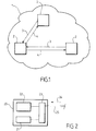
- Figure 1 shows very schematically a communications network 1 that comprises a plurality of network elements 2 interconnected by links not shown.
- the topology, number of network elements and physical layer technology employed for the interconnection may be of any type.
- the term 'network element' encompasses a variety of communicating devices, e.g. terminals, switches, routers, work stations, network management consoles and the like.
- Various automated processes executed by the network elements 2 cause flows of messages 3, 4 to be recurrently exchanged between the interconnected network elements 2. Such processes are typically controlled by operating systems or protocol engines of various types.
- recurrent flows of messages may be generated in accordance with:
- a monitoring process that may be implemented in the network of Fig. 1 is based on the monitoring of at least one flow of messages that arrives at a network element 2 over time and/or that is transmitted by the network element 2 over time.
- the monitoring process operates as follows:
- the monitoring process is based on the assumption that flows of messages generated by protocol engines are expected to occur at an approximately constant rate or at a rather small number of different rates. This assumption stems from the observation that protocol engines are typically implemented with preset protocol parameters such as timeouts, refresh periods and the like, which cause the protocol processes to execute on a steady time basis.
- the monitoring process is also based on the assumption that small fluctuations in the time of arrival or time of transmission of messages are acceptable and indeed expected due to transient phenomena in individual network elements, such as traffic load variations, CPU load variations, buffer occupation variations and the like. Therefore such small fluctuations are not to be construed as abnormal states of network elements.
- the process aims at detecting phenomena that occur over a long period of time compared to the inter-arrival times of the messages, e.g. long-term monotonous evolution or divergence of the message rate, long-term wandering evolution of the message rate and other similar phenomena likely to become a threat for the proper functioning of the communications network.
- the time scales involved in the process may be vary to a large extent, depending on the specifics of the system to be monitored.
- the monitoring process is implemented at several levels that operate on different time scales.
- the monitoring process may be executed by a computer-implemented monitoring module disposed in a network element that receives or transmits the flow of messages or in a separate device, e.g. a network management system connected to the network elements.
- a computer-implemented monitoring module disposed in a network element that receives or transmits the flow of messages or in a separate device, e.g. a network management system connected to the network elements.
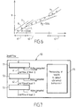
- FIG. 2 is a functional representation of a network element 20 that includes a monitoring module 21 to execute such a monitoring process.
- Network element 20 includes a protocol engine 22, e.g. OSPF routing engine, which sends and receives protocol messages through a communication module 23.
- Communication module 23 is connected to further network elements by physical links 25 and employs a protocol stack for communicating the protocol messages, for example a TCP/IP stack or other.
- Monitoring module 21 cooperates with protocol engine 22 and/or communication module 23 to detect an incoming flow of messages 24 in accordance with predefined criteria and takes the detected time of arrival of the messages as an input for computing the modelized, i.e. estimated rates of the messages over time.
- the flow of messages consists of Link State Advertisements (LSA) addressed to the network element 20 in accordance with an OSPF routing protocol.
- LSA Link State Advertisements
- the consecutive messages of the flow that are detected at the network element 20 are represented by points P n , where n is a positive integer that denotes the rank of the message in the flow (assuming FIFO), which is shown on the ordinate axis y.
- the abscissae x represent the time of arrival of the messages.
- a computational model is employed to predict a time window.
- the model in the example illustrated uses five parameters:
- the critical points P 0 and P 0 are initially identical to P 0 .
- the line U 0 denotes the early boundary computed as a function of critical point P 0 and parameter ⁇ , as shown by arrow 30.
- the line L 0 denotes the late boundary computed as a function of critical point P 0 and parameter T, as shown by arrow 31.
- Boundaries U n and L n define the predicted time window for the n+1-th message to be received.
- the time window can also be referred to as a 'tube' due to its representation in the graphics.
- Figure 3 illustrates a message P 1 than arrived within the time window defined by U 0 and L 0 .
- Message P 1 does not cause the rate ⁇ to be updated.
- Figure 3 illustrates a subsequent message P 2 than arrived within the time window defined by U 1 and L 4 .
- Message P 2 does not cause the rate ⁇ to be updated either.
- each message arrived within the time window may cause an update of one of the critical points so as to narrow down the time window for subsequent messages.
- FIG 4 the case where a subsequent message arrives later than the predicted time window is illustrated by message P3, which is beyond line L 2 , i.e. out of the 'tube'.
- the parameter ⁇ is updated to reflect a new rate of arrival of the messages, which is computed as a function of the actual time of arrival of message P 3 .
- the initial rate and the new rate are stored to serve for detection of anomalies. The process then reinitializes from point P3.
- FIG 5 the case where a subsequent message arrives later than the predicted time window is illustrated by message P4, which is beyond line U 3 , i.e. out of the 'tube'.
- the parameter ⁇ is updated to reflect a new rate of arrival of the messages, which is computed as a function of the actual time of arrival of message P 4 .
- the initial rate and the new rate are stored to serve for detection of anomalies. The process then reinitializes from point P 4 .
- figures 4 and 5 depict two different sequences of messages for the sake of illustration.
- Figure 6 shows the outlook of the flow of messages and corresponding tube resulting from applying the above computational model over time.
- the flow of messages appears as a sequence of consecutive periods 41, 42, 43 each with a given constant rate of arrival.
- the third period corresponds to the same rate as the first period. This may represent a healthy system where two operations take place alternatively and involve a different rate of messages.
- the modeled rate follows a monotonous i.e. diverging evolution over a certain period of time, an alarm may be raised.
- FIG 7 there is shown a second embodiment of a monitoring module 50 that include several consecutive levels 51, 52, 53.
- the rate computation module of first level 51 operates exactly as described above in reference of figure 3 to 6 .
- it produces a filtered flow of the messages that includes only detected messages of the input flow that cause the modeled rate to be updated, i.e. constraint-breaking messages.
- the output filtered flow shown by arrow 61 comprises a smaller number of messages with a larger inter-arrival interval.
- Filtered flow 61 serves as the input flow for the rate computation module of second level 52, which operates in the same manner.
- module of second level 52 makes it possible to observe the flow of messages over a larger time scale, still with very limited computational costs, to detect signs of unhealthy phenomena, e.g. divergence or wandering.
- Any number of consecutive rate computation levels can be implemented in the same manner to provide monitoring over increasingly large time scales, e.g. minutes, hours, days, months or years.
- the results produced by the first and final level are the most significant.
- the first level curve stability directly describes the stability of the system.
- the last level curve will show if the system is divergent compared to theoretical models, i.e. assumptions mentioned above.
- Figures 8 to 11 illustrate an example of a diverging system in which the rate of messages is monotonously decreasing over a large period time, i.e. about 80,000 seconds.
- Figures 9 , 10 and 11 show the corresponding evolution of the modelized rates as computed by the first level rate computation module 51, second level rate computation module 52 and third level rate computation module 53 over the same period of time. In the divergent situation depicted, all levels consistently show a reduction of the rate over time. However, it is readily seen that the higher the level of the rate computation module, the lower the number of changes experienced by the modelized rate of messages. In addition, the higher the level of the rate computation module is, the more monotonous the evolution of the rate. Namely in figure 11 , almost all changes of the modelized rate consist of a decrease, whereas changes in both directions can be observed in almost equal numbers in figure 9 . This decreasing trend would be even more monotonous in a fourth or fifth level rate computation module (not shown).
- the third level module makes it possible to detect a clear decreasing trend already at 30,000 s or before, whereas the output of the first level module can be interpreted as a noisy signal without any clear trend.
- the decision module 55 triggers an alarm as soon as the output of the third or fourth level rate computation module shows 15 changes in the same direction out of the last 20 changes of the computed rate.
- the above described processes make it possible to detect rate change events in a flow of messages over one or more time scales and at a rather low computational cost.
- the detected events can serve as an input for post-processing steps intended to detect or confirm the occurrence of specific situations within the network element and/or network.
- post processing may involve a number of mathematical methods, e.g. linear regression, polynomial curve fitting and the like.
- control units or modules could be e.g. hardware means like e.g. an ASIC, or a combination of hardware and software means, e.g. an ASIC and an FPGA, or at least one microprocessor and at least one memory with software modules located therein.
- a network management system can be a hardware device, for example a personal computer, a workstation, an Internet appliance, or other general purpose or specific purpose communications device.
- a software program running on this system performs network management functions to control the network elements.
Landscapes
- Engineering & Computer Science (AREA)
- Computer Networks & Wireless Communication (AREA)
- Signal Processing (AREA)
- Mathematical Analysis (AREA)
- Algebra (AREA)
- General Physics & Mathematics (AREA)
- Physics & Mathematics (AREA)
- Mathematical Optimization (AREA)
- Mathematical Physics (AREA)
- Probability & Statistics with Applications (AREA)
- Pure & Applied Mathematics (AREA)
- Data Exchanges In Wide-Area Networks (AREA)
- Computer And Data Communications (AREA)
- Communication Control (AREA)
Abstract
detecting a flow of messages at an interface of the communication device,
recording a sequence of message events (P) over time, wherein a message event comprises a date of a detected message of the flow,
computing a modelized rate of the messages over time as a function of the sequence of message events (P),
and detecting a sequence of rate change events over time, wherein a rate change event comprises an updated value of the modelized rate of the messages. The method repeatedly performs the steps of predicting a time-window (U, L) for the date of a subsequent message event (P) and, if the date of the subsequent message event is out of the predicted time-window, detecting a rate change event.
Description
- The invention relates to the technical field of monitoring of communication devices, in particular communications networks and network elements thereof.
- Communications networks have grown more and more complex in terms of architecture and also in terms of implemented processes, protocols and services. The increasing complexity poses a challenge to network operators in charge of ensuring faultless operations.
- Some studies about detection of anomalies in communications systems focus on failures, interruption of service or bad configuration that crash the network. However, reactive management methods aiming at resolving operating problems once they arise are less and less adapted to large interconnected systems where recovery from a crash would involve huge amounts of time and resources.
- In an embodiment, the invention provides a method for monitoring a communication device, comprising:
- detecting a flow of messages at an interface of the communication device,
- recording a sequence of message events over time, wherein a message event comprises a date of a detected message of the flow,
- computing a modelized rate of the messages over time as a function of the sequence of message events,
- detecting a sequence of rate change events over time, wherein a rate change event comprises an updated value of the modelized rate of the messages.
- The method can be implemented with a flow of incoming messages received by the communication device from its environment. The method can also be implemented with a flow of messages transmitted by the communication device to its environment.
- According to embodiments, such a method can comprise one or more of the features below.
- In embodiments the method further comprises detecting an abnormal state of the communication device as a function of the sequence of rate change events.
- In embodiments the abnormal state is detected in response to a monotonous evolution of the modelized rate over a long period of time, which hints at a diverging behavior of the device. In embodiments the abnormal state is detected as a function of a number of different modelized rates that have been obtained over time, e.g. when that number becomes higher than a given threshold, thus hinting at a long-term instability of the communications device.
- The computation of the modelized rate of the messages and subsequent detection of rate change events over time can be done with a number of mathematical models, e.g. by calculating a linear regression function of the message events over a sliding time window. More refined statistical correlations could be computed as well, although computational cost should generally be kept sufficiently low for a real time implementation of the method to be possible.
- In embodiments the steps of computing a modelized rate of the messages over time and detecting a sequence of rate change events over time comprises repeatedly performing the steps of:
- predicting a time-window for the date of a subsequent message event of the sequence of message events as a function of past message events of the sequence of message events and a current modelized rate of the messages,
- if the date of the subsequent message event of the sequence of message events is out of the predicted time-window, detecting a rate change event and updating the modelized rate as a function of the date of the subsequent message event.
- In embodiments, the updating of the modelized rate comprises:
- computing an actual rate of the messages as a function of the detected date of the subsequent message event of the sequence (i.e. subsequent message of the flow) and the date of an earlier message event of the sequence, and
- taking the actual rate as the new current modelized rate.
- In embodiments, the repeated steps further comprise:
- if the detected date of the subsequent message event is within the predicted time-window, updating the time-window as a function of detected date of the subsequent message event so as to narrow down the time-window.
- In embodiments, the updating of the time-window comprises:
- computing an actual rate of the messages as a function of the detected date of the subsequent message event of the sequence, and
- advancing a latest boundary of the time-window if the actual rate is above the current modelized rate and delaying an earliest boundary of the time window if the actual rate is below the current modelized rate.
- In embodiments, at least one of an earliest boundary and a latest boundary of the time-window is computed as a function of the rank of the subsequent message event in the sequence of message events divided by the current modelized rate.
- In embodiments, an earliest boundary of the time-window is computed as a function of a positive parameter representing a maximum number of messages of the flow that may arrive simultaneously at the communication device in a normal state of the communication device.
- In embodiments, a latest boundary of the time-window is computed as a function of a positive parameter representing a maximum period of time during which no message of the flow may be detected at the communication device in a normal state of the communication device.
- Such monitoring operations can be implemented over different time scales, depending on underlying parameters that influence operations the communication device, e.g. timers, refresh parameters, time out parameters of protocol engines and the like. The method can be implemented a multiple consecutive levels to provide a respective monitoring over increasingly long time scales.
- In corresponding embodiments, the steps of computing a modelized rate of the messages over time and detecting a sequence of rate change events over time constitute a monitoring operation at a first level, and the method further comprises:
- filtering the sequence of message events as a function of the rate change events detected during the first-level monitoring operation, and
- performing again said steps of computing a current modelized rate of the messages over time and detecting a sequence of rate change events over time by taking the filtered sequence of message events as an input instead of the sequence of message events.
- In embodiments, the step of filtering the sequence of message events retains only message events that caused detection of a rate change event.
- In embodiments, the method further comprises one or more further monitoring operations at consecutive levels, each further monitoring operation comprising: filtering the sequence of message events taken as an input for the monitoring operation at the previous level so as to retain only message events that caused a rate change event to be detected during the monitoring operation at the previous level,
performing again the steps of computing a current modelized rate of the messages over time and detecting a sequence of rate change events over time by taking the filtered sequence of message events as an input. - Any number of monitoring levels can be provided in this manner, e.g. up to five consecutive levels. In embodiments, the detecting of an abnormal evolution of the communication device is performed as a function of the sequence of the modelized rates over time computed during the monitoring operation at one or more levels. In embodiments, the monitoring operation at a highest level provides the main input for detecting the abnormal behavior, e.g. as a long-term divergence of a process occurring within the communications system.
- The flow of messages that serves to implement the monitoring method can be defined in several ways, e.g. as a function of one or more parameters selected among protocol, message type, LANA number, source address, destination address. In embodiments, the flow of messages is made up of messages generated in accordance with a predefmed protocol, e.g. a routing protocol or a network management protocol.
- Messages exchanged by routing engines are of peculiar relevance for the monitoring of in IP networks since they are responsible for maintaining a consistent picture of the network topology among distant network elements. Especially link-state routing protocols such as Open Shortest Path First (OSPF) and its derivatives involve recurrent flows of messages between routers that are supposed to follow an overall steady rate.
- In an embodiment, the invention provides a computer program comprising executable code that causes a computer to perform all the steps of the above- described monitoring methods when executed.
- Aspects of the invention are based on the idea of monitoring and detecting malicious or hidden anomalies that may only become apparent over a long period of time by exploiting a memory of the past evolution of a flow of messages.
- Aspects of the invention are based on the idea of proactively detecting hidden and malicious issues that may or will become a threat for the communications system.
- Aspects of the invention are based on the idea of providing monitoring methods having very light computational requirements and suitable for real-time monitoring of communication devices and networks.
- These and other aspects of the invention will be apparent from and elucidated with reference to the embodiments described hereinafter, by way of example, with reference to the drawings.
-
Figure 1 is a functional representation of a communications network in which monitoring methods can be used to detect anomalies over time. -
Figure 2 is a functional representation of a network element comprising a monitoring module. -
Figures 3 to 5 are graphics showing the arrival of consecutive messages of a flow over time and calculation steps for determining corresponding modelized rates. -
Figure 6 is a graphic showing a sequence of modelized rates over time that may be obtained in an embodiment. -
Figure 7 is a functional representation of a multi-level monitoring device. -
Figures 8 to 11 illustrate an example of a flow of messages having a monotonously decreasing rate over a large period time and the modelized rates computed at several consecutive levels. -
Figure 1 shows very schematically acommunications network 1 that comprises a plurality ofnetwork elements 2 interconnected by links not shown. The topology, number of network elements and physical layer technology employed for the interconnection may be of any type. The term 'network element' encompasses a variety of communicating devices, e.g. terminals, switches, routers, work stations, network management consoles and the like. Various automated processes executed by thenetwork elements 2 cause flows ofmessages interconnected network elements 2. Such processes are typically controlled by operating systems or protocol engines of various types. - For example, recurrent flows of messages may be generated in accordance with:
- routing protocols, e.g. link-state routing protocols like OSPF, to refresh adjacencies between nodes or update network topology,
- signaling protocols, e.g. RSVP and the like, to refresh or update MPLS tunnels,
- network management protocols, e.g. SNMP, to collect reports from management agents,
- alarms generated by the network.
- A monitoring process that may be implemented in the network of
Fig. 1 is based on the monitoring of at least one flow of messages that arrives at anetwork element 2 over time and/or that is transmitted by thenetwork element 2 over time. The monitoring process operates as follows: - The monitoring is initialized with initial parameters defining an initial modelized rate, e.g. rate of arrival or rate of transmission, and a time window prediction model. For example, the modelized rate can be initialized at a preset value or at a measured value, i.e. an actual rate of messages measured before the monitoring process actually begins, e.g. measured over two or more messages already arrived or transmitted.
- The time window prediction model is employed to compute a time window for each subsequent message of the flow, representing a period of time in which reception or transmission of the subsequent message is expected to occur. The modelized rate represents an average rate at which the messages of the flow are currently expected to be sent or received.
- As long as subsequent messages occur within the predicted time windows, operations in the network element are deemed normal. The time windows represent acceptable ranges of fluctuation of the messages in time with respect to the modelized rate.
- When a subsequent message occurs out of the corresponding time window, the actual date of the message serves to update the modelized rate. Preferably, the message is also recorded and marked as a special event for the purpose of further monitoring steps.
- The process continues with the updated value of the modelized rate, i.e. a rate estimated in accordance with a given computation model.
- The values of the modelized rate that are consecutively obtained over time are recorded and processed to detect an abnormal state of the network element or group of network elements involved in the monitored flow of messages.
- The monitoring process is based on the assumption that flows of messages generated by protocol engines are expected to occur at an approximately constant rate or at a rather small number of different rates. This assumption stems from the observation that protocol engines are typically implemented with preset protocol parameters such as timeouts, refresh periods and the like, which cause the protocol processes to execute on a steady time basis.
- The monitoring process is also based on the assumption that small fluctuations in the time of arrival or time of transmission of messages are acceptable and indeed expected due to transient phenomena in individual network elements, such as traffic load variations, CPU load variations, buffer occupation variations and the like. Therefore such small fluctuations are not to be construed as abnormal states of network elements. By contrast, the process aims at detecting phenomena that occur over a long period of time compared to the inter-arrival times of the messages, e.g. long-term monotonous evolution or divergence of the message rate, long-term wandering evolution of the message rate and other similar phenomena likely to become a threat for the proper functioning of the communications network.
- The time scales involved in the process may be vary to a large extent, depending on the specifics of the system to be monitored. Preferably, the monitoring process is implemented at several levels that operate on different time scales.
- The monitoring process may be executed by a computer-implemented monitoring module disposed in a network element that receives or transmits the flow of messages or in a separate device, e.g. a network management system connected to the network elements.
-
Figure 2 is a functional representation of anetwork element 20 that includes amonitoring module 21 to execute such a monitoring process.Network element 20 includes aprotocol engine 22, e.g. OSPF routing engine, which sends and receives protocol messages through acommunication module 23.Communication module 23 is connected to further network elements byphysical links 25 and employs a protocol stack for communicating the protocol messages, for example a TCP/IP stack or other.Monitoring module 21 cooperates withprotocol engine 22 and/orcommunication module 23 to detect an incoming flow ofmessages 24 in accordance with predefined criteria and takes the detected time of arrival of the messages as an input for computing the modelized, i.e. estimated rates of the messages over time. - With reference to
figures 3 to 5 , an embodiment of the monitoring process executed by monitoringmodule 21 will now be described in further details. For the sake of illustration, the flow of messages consists of Link State Advertisements (LSA) addressed to thenetwork element 20 in accordance with an OSPF routing protocol. - In
figures 3 to 5 , the consecutive messages of the flow that are detected at thenetwork element 20 are represented by points Pn, where n is a positive integer that denotes the rank of the message in the flow (assuming FIFO), which is shown on the ordinate axis y. The abscissae x represent the time of arrival of the messages. With this representation, the flow is a non-decreasing sequence (Xn), with X0 = 0 by convention and where Xn is the time of arrival of the n-th message of the flow. The n-th message of the flow is denoted:
- For each subsequent message, a computational model is employed to predict a time window. The model in the example illustrated uses five parameters:
- p=tan(a) denotes the current arrival rate of the messages. This parameter is initialized at a positive value at the beginning of the algorithm and updated every time a subsequent message arrives out of the predicted time window.
- T is a positive parameter that serves to define a latest boundary of the time window, also referred to as Lower constraint Ln. The quantity ρ T schematically represents the number of messages that can be lost simultaneously.
- σ is a positive parameter that serves to define an earliest boundary of the time window, also referred to as Upper constraint Un. The quantity σ schematically represents the number of messages that can arrive simultaneously at the network element.
-
P represents the past message that arrived after the last update of ρ and that lies the closest to the latest boundary of the time window, i.e. the closest to the Lower constraint curve Ln. This point is referred to as upper critical message and serves to update the Upper constraint Un whenever it is updated. - P represents the past message that arrived after the last update of ρ and that lies the closest to the earliest boundary of the time window, i.e. the closest to the Upper constraint curve Un. This point is referred to as lower critical message and serves to update the Lower constraint Ln whenever it is updated.
- Referring to
Figure 3 , P0 and α=Arctan(ρ) show the initial state of the model. The critical pointsP 0 and P 0 are initially identical to P0. The line U0 denotes the early boundary computed as a function of critical pointP 0 and parameter σ, as shown byarrow 30. The line L0 denotes the late boundary computed as a function of critical point P 0 and parameter T, as shown by arrow 31. Boundaries Un and Ln define the predicted time window for the n+1-th message to be received. At any step, the boundaries Un and Ln are defined as linear functions of time with slope ρ=tan(α). As a consequence the time window can also be referred to as a 'tube' due to its representation in the graphics. -
Figure 3 illustrates a message P1 than arrived within the time window defined by U0 and L0. Message P1 does not cause the rate ρ to be updated.Figure 3 illustrates a subsequent message P2 than arrived within the time window defined by U1 and L4. Message P2 does not cause the rate ρ to be updated either. However each message arrived within the time window may cause an update of one of the critical points so as to narrow down the time window for subsequent messages. - More precisely, when the subsequent message arrives at a later time than the time predicted by tracing a line with slope ρ from the current upper critical point, the message becomes the new upper critical point. This illustrated by point P1 and line 32 in
Figure 3 . Conversely, when the subsequent message arrives at an earlier time than the time predicted by tracing a line with slope ρ from the current lower critical point, the message becomes the new critical point. This illustrated by point P2 and line 32 inFigure 3 . At each message, the upper and lower boundaries are updated as a function of the updated critical points, as shown byarrows 33 and 34. - Turning now to
figure 4 , the case where a subsequent message arrives later than the predicted time window is illustrated by message P3, which is beyond line L2, i.e. out of the 'tube'. In this case, the parameter ρ is updated to reflect a new rate of arrival of the messages, which is computed as a function of the actual time of arrival of message P3. As shown, the new rate of arrival is the slope of the line joining the constraint-breaking message P3 with the current upper critical point, here P1=P 1. The initial rate and the new rate are stored to serve for detection of anomalies. The process then reinitializes from point P3. - Turning now to
figure 5 , the case where a subsequent message arrives later than the predicted time window is illustrated by message P4, which is beyond line U3, i.e. out of the 'tube'. In this case, the parameter ρ is updated to reflect a new rate of arrival of the messages, which is computed as a function of the actual time of arrival of message P4. As shown, the new rate of arrival is the slope of the line joining the constraint-breaking message P4 with the current lower critical point, here P3=P 3. The initial rate and the new rate are stored to serve for detection of anomalies. The process then reinitializes from point P4. It should be noted thatfigures 4 and5 depict two different sequences of messages for the sake of illustration. -
Figure 6 shows the outlook of the flow of messages and corresponding tube resulting from applying the above computational model over time. Namely, the flow of messages appears as a sequence ofconsecutive periods - The above-described process makes it possible to monitor one or more flow of messages in real time to detect anomalies. Indeed the computational cost of the process is very limited. Pseudo-code for implementing the above-described process is appended in Table 1.
- Turning to
figure 7 , there is shown a second embodiment of amonitoring module 50 that include severalconsecutive levels first level 51 operates exactly as described above in reference offigure 3 to 6 . In addition, it produces a filtered flow of the messages that includes only detected messages of the input flow that cause the modeled rate to be updated, i.e. constraint-breaking messages. As a consequence the output filtered flow shown byarrow 61 comprises a smaller number of messages with a larger inter-arrival interval. - Filtered
flow 61 serves as the input flow for the rate computation module ofsecond level 52, which operates in the same manner. As a consequence, module ofsecond level 52 makes it possible to observe the flow of messages over a larger time scale, still with very limited computational costs, to detect signs of unhealthy phenomena, e.g. divergence or wandering. - Any number of consecutive rate computation levels can be implemented in the same manner to provide monitoring over increasingly large time scales, e.g. minutes, hours, days, months or years.
- The results produced by the first and final level are the most significant. The first level curve stability directly describes the stability of the system. The last level curve will show if the system is divergent compared to theoretical models, i.e. assumptions mentioned above. These results make it possible to observe in real-time the symptoms of hidden/malicious behavior of control flow by using these results as "health indicators".
-
Figures 8 to 11 illustrate an example of a diverging system in which the rate of messages is monotonously decreasing over a large period time, i.e. about 80,000 seconds.Figure 8 shows the flow of messages, i.e. the cumulative number of messages received by the node being monitored from time = 0 to time = 80,000. -
Figures 9 ,10 and 11 show the corresponding evolution of the modelized rates as computed by the first levelrate computation module 51, second levelrate computation module 52 and third levelrate computation module 53 over the same period of time. In the divergent situation depicted, all levels consistently show a reduction of the rate over time. However, it is readily seen that the higher the level of the rate computation module, the lower the number of changes experienced by the modelized rate of messages. In addition, the higher the level of the rate computation module is, the more monotonous the evolution of the rate. Namely infigure 11 , almost all changes of the modelized rate consist of a decrease, whereas changes in both directions can be observed in almost equal numbers infigure 9 . This decreasing trend would be even more monotonous in a fourth or fifth level rate computation module (not shown). As a consequence, in this example, the third level module makes it possible to detect a clear decreasing trend already at 30,000 s or before, whereas the output of the first level module can be interpreted as a noisy signal without any clear trend. In an embodiment, the decision module 55 triggers an alarm as soon as the output of the third or fourth level rate computation module shows 15 changes in the same direction out of the last 20 changes of the computed rate. - The above described processes make it possible to detect rate change events in a flow of messages over one or more time scales and at a rather low computational cost. The detected events can serve as an input for post-processing steps intended to detect or confirm the occurrence of specific situations within the network element and/or network. Such post processing may involve a number of mathematical methods, e.g. linear regression, polynomial curve fitting and the like.
- Elements such as the control units or modules could be e.g. hardware means like e.g. an ASIC, or a combination of hardware and software means, e.g. an ASIC and an FPGA, or at least one microprocessor and at least one memory with software modules located therein.
- A network management system can be a hardware device, for example a personal computer, a workstation, an Internet appliance, or other general purpose or specific purpose communications device. A software program running on this system performs network management functions to control the network elements.
- The invention is not limited to the described embodiments. The appended claims are to be construed as embodying all modification and alternative constructions that may be occurred to one skilled in the art, which fairly fall within the basic teaching here, set forth.
- The use of the verb "to comprise" or "to include" and its conjugations does not exclude the presence of elements or steps other than those stated in a claim. Furthermore, the use of the article "a" or "an" preceding an element or step does not exclude the presence of a plurality of such elements or steps.
- In the claims, any reference signs placed between parentheses shall not be construed as limiting the scope of the claims.

Claims (18)
- A method for monitoring a communication device (2, 20), comprising:detecting a flow of messages (3, 4, 24) at an interface (23) of the communication device,recording a sequence of message events over time, wherein a message event comprises a date of a detected message of the flow,computing a modelized rate (p) of the messages over time as a function of the sequence of message events,detecting a sequence of rate change events over time, wherein a rate change event comprises an updated value of the modelized rate of the messages.
- A method in accordance with claim 1, wherein said steps of computing a modelized rate of the messages over time and detecting a sequence of rate change events over time comprises repeatedly performing the steps of:predicting a time-window (U, L) for the date of a subsequent message event (P) of the sequence of message events as a function of past message events of the sequence of message events and a current modelized rate (p) of the messages,if the date of the subsequent message event of the sequence of message events is out of the predicted time-window, detecting a rate change event and updating the modelized rate as a function of the date of the subsequent message event.
- A method in accordance with claim 2, wherein the updating of the modelized rate comprises:computing an actual rate of the messages as a function of the date of the subsequent message event and the date of an earlier message event of the sequence of message events, andtaking the actual rate as the new current modelized rate.
- A method in accordance with claim 2 or 3, wherein the repeated steps further comprise:if the detected date of the subsequent message is within the predicted time-window (U, L), updating the time-window as a function of detected date of the subsequent message event so as to narrow down the time-window.
- A method in accordance with claim 4, wherein the updating of the time-window comprises:computing an actual rate of the messages as a function of the detected date of the subsequent message event of the sequence, andadvancing a latest boundary (L) of the time-window if the actual rate is above the current modelized rate and delaying an earliest boundary (U) of the time window if the actual rate is below the current modelized rate.
- A method in accordance with any one of claims 2 to 5, wherein at least one of an earliest boundary and a latest boundary of the time-window is computed as a function of the rank (y) of the subsequent message event in the sequence of message events divided by the current modelized rate (p).
- A method in accordance with any one of claims 2 to 6, wherein an earliest boundary (U) of the time-window is computed as a function of a positive parameter (σ) representing a maximum number of messages of the flow that may arrive simultaneously at the communication device in a normal state of the communication device.
- A method in accordance with any one of claims 2 to 7, wherein a latest boundary (L) of the time-window is computed as a function of a positive parameter (T) representing a maximum period of time during which no message of the flow may be detected at the communication device in a normal state of the communication device.
- A method in accordance with any one of claims 1 to 8, wherein said steps of computing a modelized rate of the messages over time and detecting a sequence of rate change events over time constitute a monitoring operation at a first level (51), the method further comprising:filtering the sequence of message events as a function of the rate change events detected during the first-level monitoring operation (51), andperforming again said steps of computing a current modelized rate of the messages over time and detecting a sequence of rate change events over time by taking the filtered sequence of message events (61) as an input instead of the sequence of message events.
- A method in accordance with claim 9 taken in combination with any one of claims 2 to 8, wherein the step of filtering the sequence of message events retains only message events that caused detection of a rate change event.
- A method in accordance with claim 10, further comprising one or more further monitoring operations at consecutive levels (53), each further monitoring operation comprising:filtering the sequence of message events taken as an input for the monitoring operation at the previous level (52) so as to retain only message events that caused a rate change event to be detected during the monitoring operation at the previous level,performing again the steps of computing a current modelized rate of the messages over time and detecting a sequence of rate change events over time by taking the filtered sequence of message events (62) as an input.
- A method in accordance with claim 11, comprising monitoring operations at five consecutive levels or less.
- A method in accordance with any one of claims 1 to 12, further comprising detecting an abnormal state of the communication device as a function of the sequence of rate change events.
- A method in accordance with any one of claims 10 to 12, further comprising detecting an abnormal state of the communication device as a function the rate change events detected during the monitoring operation at one or more levels.
- A method in accordance with any one of claims 10 to 12, further comprising detecting an abnormal state of the communication device as a function of the sequence of rate change events detected during the monitoring operation at a highest level.
- A method in accordance with any one of claims 1 to 15, wherein the flow of messages is made up of messages generated in accordance with a predefined protocol.
- A method in accordance with claim 16, wherein the predefined protocol is one of a routing protocol and a network management protocol.
- A computer program comprising executable code that causes a computer to perform all the steps of a method in accordance with any one of claims 1 to 17 when executed.
Priority Applications (2)
| Application Number | Priority Date | Filing Date | Title |
|---|---|---|---|
| EP12160397.1A EP2642692B1 (en) | 2012-03-20 | 2012-03-20 | Monitoring of a communication device over time |
| PCT/EP2013/055283 WO2013139680A2 (en) | 2012-03-20 | 2013-03-14 | Monitoring of a communication device over time |
Applications Claiming Priority (1)
| Application Number | Priority Date | Filing Date | Title |
|---|---|---|---|
| EP12160397.1A EP2642692B1 (en) | 2012-03-20 | 2012-03-20 | Monitoring of a communication device over time |
Publications (2)
| Publication Number | Publication Date |
|---|---|
| EP2642692A1 true EP2642692A1 (en) | 2013-09-25 |
| EP2642692B1 EP2642692B1 (en) | 2016-03-16 |
Family
ID=47901086
Family Applications (1)
| Application Number | Title | Priority Date | Filing Date |
|---|---|---|---|
| EP12160397.1A Active EP2642692B1 (en) | 2012-03-20 | 2012-03-20 | Monitoring of a communication device over time |
Country Status (2)
| Country | Link |
|---|---|
| EP (1) | EP2642692B1 (en) |
| WO (1) | WO2013139680A2 (en) |
Cited By (1)
| Publication number | Priority date | Publication date | Assignee | Title |
|---|---|---|---|---|
| CN113660237A (en) * | 2021-08-10 | 2021-11-16 | 和中通信科技有限公司 | Industrial Internet data flow abnormity detection method based on dynamic sliding window, memory and processor |
Citations (2)
| Publication number | Priority date | Publication date | Assignee | Title |
|---|---|---|---|---|
| EP1244248A1 (en) * | 2001-03-21 | 2002-09-25 | Lucent Technologies Inc. | Method and apparatus for efficient reactive monitoring |
| US20110078302A1 (en) * | 2009-09-30 | 2011-03-31 | Dehaan Michael Paul | Systems and methods for detecting network conditions based on derivatives of event trending |
-
2012
- 2012-03-20 EP EP12160397.1A patent/EP2642692B1/en active Active
-
2013
- 2013-03-14 WO PCT/EP2013/055283 patent/WO2013139680A2/en not_active Ceased
Patent Citations (2)
| Publication number | Priority date | Publication date | Assignee | Title |
|---|---|---|---|---|
| EP1244248A1 (en) * | 2001-03-21 | 2002-09-25 | Lucent Technologies Inc. | Method and apparatus for efficient reactive monitoring |
| US20110078302A1 (en) * | 2009-09-30 | 2011-03-31 | Dehaan Michael Paul | Systems and methods for detecting network conditions based on derivatives of event trending |
Non-Patent Citations (2)
| Title |
|---|
| DESHPANDE S ET AL: "A Statistical Approach to Anomaly Detection in Interdomain Routing", BROADBAND COMMUNICATIONS, NETWORKS AND SYSTEMS, 2006. BROADNETS 2006. 3RD INTERNATIONAL CONFERENCE ON, IEEE, PISCATAWAY, NJ, USA, 1 October 2006 (2006-10-01), pages 1 - 10, XP031155948, ISBN: 978-1-4244-0424-7 * |
| THOTTAN M ET AL: "Anomaly detection in IP networks", IEEE TRANSACTIONS ON SIGNAL PROCESSING IEEE USA, vol. 51, no. 8, August 2003 (2003-08-01), pages 2191 - 2204, XP002681630, ISSN: 1053-587X * |
Cited By (2)
| Publication number | Priority date | Publication date | Assignee | Title |
|---|---|---|---|---|
| CN113660237A (en) * | 2021-08-10 | 2021-11-16 | 和中通信科技有限公司 | Industrial Internet data flow abnormity detection method based on dynamic sliding window, memory and processor |
| CN113660237B (en) * | 2021-08-10 | 2023-04-07 | 和中通信科技有限公司 | Industrial Internet data flow abnormity detection method based on dynamic sliding window, memory and processor |
Also Published As
| Publication number | Publication date |
|---|---|
| WO2013139680A2 (en) | 2013-09-26 |
| WO2013139680A3 (en) | 2013-11-14 |
| EP2642692B1 (en) | 2016-03-16 |
Similar Documents
| Publication | Publication Date | Title |
|---|---|---|
| US11134126B2 (en) | Adaptive routing of branch traffic in software-defined wide area network (SDWAN) deployments | |
| EP3439241B1 (en) | Using machine learning to monitor link quality and predict link faults | |
| US12058010B2 (en) | Adaptive stress testing of SD-WAN tunnels for what-if scenario model training | |
| US9774522B2 (en) | Triggering reroutes using early learning machine-based prediction of failures | |
| US11240122B2 (en) | Event-triggered machine learning for rare event forecasting in a software defined wide area Network (SD-WAN) | |
| US9794145B2 (en) | Scheduling predictive models for machine learning systems | |
| US11381471B2 (en) | System and method for predicting and handling short-term overflow | |
| US11695682B2 (en) | Optimizing Border Gateway Protocol (BGP) traffic using reinforcement learning | |
| EP3661133A1 (en) | Delay-based transmission path control method, network controller and system | |
| US20050243729A1 (en) | Method and apparatus for automating and scaling active probing-based IP network performance monitoring and diagnosis | |
| CN111147287A (en) | A network simulation method and system in an SDN scenario | |
| US20200382414A1 (en) | ENSURING BACKUP PATH PERFORMANCE FOR PREDICTIVE ROUTING IN SD-WANs | |
| US20190149440A1 (en) | Traffic analytics service for telemetry routers and monitoring systems | |
| CN113938407A (en) | Method and device for fault detection of data center network based on in-band network telemetry system | |
| CN104270277A (en) | Alarming information processing method and alarming information processing device | |
| CN111651859B (en) | Method and device for evaluating elastic performance of communication satellite constellation system | |
| US11811644B2 (en) | Distributed predictive routing using lightweight state tracking | |
| EP3264634A1 (en) | Automatically detecting an error in a communication and automatically determining a source of the error | |
| EP2629453A1 (en) | Method, apparatus and system for setting a size of an event correlation time window | |
| US20170295080A1 (en) | Monitoring connections for data communications | |
| EP2642692B1 (en) | Monitoring of a communication device over time | |
| US20200336395A1 (en) | Identification of candidate problem network entities | |
| US11985069B2 (en) | Auto-detection of application failures for forecasting network path performance | |
| US10439941B2 (en) | Determining switch load values for switches | |
| Musunuru et al. | Optimizing Hot Standby Redundancy Using AI for Network Traffic Balancing and Failover Management |
Legal Events
| Date | Code | Title | Description |
|---|---|---|---|
| PUAI | Public reference made under article 153(3) epc to a published international application that has entered the european phase |
Free format text: ORIGINAL CODE: 0009012 |
|
| 17P | Request for examination filed |
Effective date: 20130201 |
|
| AK | Designated contracting states |
Kind code of ref document: A1 Designated state(s): AL AT BE BG CH CY CZ DE DK EE ES FI FR GB GR HR HU IE IS IT LI LT LU LV MC MK MT NL NO PL PT RO RS SE SI SK SM TR |
|
| AX | Request for extension of the european patent |
Extension state: BA ME |
|
| 17Q | First examination report despatched |
Effective date: 20130913 |
|
| RBV | Designated contracting states (corrected) |
Designated state(s): AL AT BE BG CH CY CZ DE DK EE ES FI FR GB GR HR HU IE IS IT LI LT LU LV MC MK MT NL NO PL PT RO RS SE SI SK SM TR |
|
| RAP1 | Party data changed (applicant data changed or rights of an application transferred) |
Owner name: INRIA - INSTITUT NATIONAL DE RECHERCHE EN INFORMAT Owner name: ALCATEL LUCENT |
|
| GRAP | Despatch of communication of intention to grant a patent |
Free format text: ORIGINAL CODE: EPIDOSNIGR1 |
|
| INTG | Intention to grant announced |
Effective date: 20151102 |
|
| GRAS | Grant fee paid |
Free format text: ORIGINAL CODE: EPIDOSNIGR3 |
|
| GRAA | (expected) grant |
Free format text: ORIGINAL CODE: 0009210 |
|
| AK | Designated contracting states |
Kind code of ref document: B1 Designated state(s): AL AT BE BG CH CY CZ DE DK EE ES FI FR GB GR HR HU IE IS IT LI LT LU LV MC MK MT NL NO PL PT RO RS SE SI SK SM TR |
|
| REG | Reference to a national code |
Ref country code: GB Ref legal event code: FG4D |
|
| REG | Reference to a national code |
Ref country code: CH Ref legal event code: EP |
|
| REG | Reference to a national code |
Ref country code: IE Ref legal event code: FG4D |
|
| REG | Reference to a national code |
Ref country code: AT Ref legal event code: REF Ref document number: 782027 Country of ref document: AT Kind code of ref document: T Effective date: 20160415 |
|
| REG | Reference to a national code |
Ref country code: DE Ref legal event code: R096 Ref document number: 602012015569 Country of ref document: DE |
|
| REG | Reference to a national code |
Ref country code: FR Ref legal event code: PLFP Year of fee payment: 5 |
|
| REG | Reference to a national code |
Ref country code: NL Ref legal event code: MP Effective date: 20160316 |
|
| REG | Reference to a national code |
Ref country code: LT Ref legal event code: MG4D |
|
| PG25 | Lapsed in a contracting state [announced via postgrant information from national office to epo] |
Ref country code: GR Free format text: LAPSE BECAUSE OF FAILURE TO SUBMIT A TRANSLATION OF THE DESCRIPTION OR TO PAY THE FEE WITHIN THE PRESCRIBED TIME-LIMIT Effective date: 20160617 Ref country code: FI Free format text: LAPSE BECAUSE OF FAILURE TO SUBMIT A TRANSLATION OF THE DESCRIPTION OR TO PAY THE FEE WITHIN THE PRESCRIBED TIME-LIMIT Effective date: 20160316 Ref country code: NO Free format text: LAPSE BECAUSE OF FAILURE TO SUBMIT A TRANSLATION OF THE DESCRIPTION OR TO PAY THE FEE WITHIN THE PRESCRIBED TIME-LIMIT Effective date: 20160616 Ref country code: HR Free format text: LAPSE BECAUSE OF FAILURE TO SUBMIT A TRANSLATION OF THE DESCRIPTION OR TO PAY THE FEE WITHIN THE PRESCRIBED TIME-LIMIT Effective date: 20160316 |
|
| REG | Reference to a national code |
Ref country code: AT Ref legal event code: MK05 Ref document number: 782027 Country of ref document: AT Kind code of ref document: T Effective date: 20160316 |
|
| PG25 | Lapsed in a contracting state [announced via postgrant information from national office to epo] |
Ref country code: RS Free format text: LAPSE BECAUSE OF FAILURE TO SUBMIT A TRANSLATION OF THE DESCRIPTION OR TO PAY THE FEE WITHIN THE PRESCRIBED TIME-LIMIT Effective date: 20160316 Ref country code: LT Free format text: LAPSE BECAUSE OF FAILURE TO SUBMIT A TRANSLATION OF THE DESCRIPTION OR TO PAY THE FEE WITHIN THE PRESCRIBED TIME-LIMIT Effective date: 20160316 Ref country code: BE Free format text: LAPSE BECAUSE OF NON-PAYMENT OF DUE FEES Effective date: 20160331 Ref country code: NL Free format text: LAPSE BECAUSE OF FAILURE TO SUBMIT A TRANSLATION OF THE DESCRIPTION OR TO PAY THE FEE WITHIN THE PRESCRIBED TIME-LIMIT Effective date: 20160316 Ref country code: LV Free format text: LAPSE BECAUSE OF FAILURE TO SUBMIT A TRANSLATION OF THE DESCRIPTION OR TO PAY THE FEE WITHIN THE PRESCRIBED TIME-LIMIT Effective date: 20160316 Ref country code: SE Free format text: LAPSE BECAUSE OF FAILURE TO SUBMIT A TRANSLATION OF THE DESCRIPTION OR TO PAY THE FEE WITHIN THE PRESCRIBED TIME-LIMIT Effective date: 20160316 |
|
| PG25 | Lapsed in a contracting state [announced via postgrant information from national office to epo] |
Ref country code: EE Free format text: LAPSE BECAUSE OF FAILURE TO SUBMIT A TRANSLATION OF THE DESCRIPTION OR TO PAY THE FEE WITHIN THE PRESCRIBED TIME-LIMIT Effective date: 20160316 Ref country code: IS Free format text: LAPSE BECAUSE OF FAILURE TO SUBMIT A TRANSLATION OF THE DESCRIPTION OR TO PAY THE FEE WITHIN THE PRESCRIBED TIME-LIMIT Effective date: 20160716 Ref country code: PL Free format text: LAPSE BECAUSE OF FAILURE TO SUBMIT A TRANSLATION OF THE DESCRIPTION OR TO PAY THE FEE WITHIN THE PRESCRIBED TIME-LIMIT Effective date: 20160316 |
|
| REG | Reference to a national code |
Ref country code: CH Ref legal event code: PL |
|
| PG25 | Lapsed in a contracting state [announced via postgrant information from national office to epo] |
Ref country code: RO Free format text: LAPSE BECAUSE OF FAILURE TO SUBMIT A TRANSLATION OF THE DESCRIPTION OR TO PAY THE FEE WITHIN THE PRESCRIBED TIME-LIMIT Effective date: 20160316 Ref country code: CZ Free format text: LAPSE BECAUSE OF FAILURE TO SUBMIT A TRANSLATION OF THE DESCRIPTION OR TO PAY THE FEE WITHIN THE PRESCRIBED TIME-LIMIT Effective date: 20160316 Ref country code: ES Free format text: LAPSE BECAUSE OF FAILURE TO SUBMIT A TRANSLATION OF THE DESCRIPTION OR TO PAY THE FEE WITHIN THE PRESCRIBED TIME-LIMIT Effective date: 20160316 Ref country code: PT Free format text: LAPSE BECAUSE OF FAILURE TO SUBMIT A TRANSLATION OF THE DESCRIPTION OR TO PAY THE FEE WITHIN THE PRESCRIBED TIME-LIMIT Effective date: 20160718 Ref country code: AT Free format text: LAPSE BECAUSE OF FAILURE TO SUBMIT A TRANSLATION OF THE DESCRIPTION OR TO PAY THE FEE WITHIN THE PRESCRIBED TIME-LIMIT Effective date: 20160316 Ref country code: SM Free format text: LAPSE BECAUSE OF FAILURE TO SUBMIT A TRANSLATION OF THE DESCRIPTION OR TO PAY THE FEE WITHIN THE PRESCRIBED TIME-LIMIT Effective date: 20160316 Ref country code: SK Free format text: LAPSE BECAUSE OF FAILURE TO SUBMIT A TRANSLATION OF THE DESCRIPTION OR TO PAY THE FEE WITHIN THE PRESCRIBED TIME-LIMIT Effective date: 20160316 |
|
| REG | Reference to a national code |
Ref country code: DE Ref legal event code: R097 Ref document number: 602012015569 Country of ref document: DE |
|
| REG | Reference to a national code |
Ref country code: IE Ref legal event code: MM4A |
|
| PG25 | Lapsed in a contracting state [announced via postgrant information from national office to epo] |
Ref country code: BE Free format text: LAPSE BECAUSE OF FAILURE TO SUBMIT A TRANSLATION OF THE DESCRIPTION OR TO PAY THE FEE WITHIN THE PRESCRIBED TIME-LIMIT Effective date: 20160316 Ref country code: IT Free format text: LAPSE BECAUSE OF FAILURE TO SUBMIT A TRANSLATION OF THE DESCRIPTION OR TO PAY THE FEE WITHIN THE PRESCRIBED TIME-LIMIT Effective date: 20160316 |
|
| PLBE | No opposition filed within time limit |
Free format text: ORIGINAL CODE: 0009261 |
|
| STAA | Information on the status of an ep patent application or granted ep patent |
Free format text: STATUS: NO OPPOSITION FILED WITHIN TIME LIMIT |
|
| PG25 | Lapsed in a contracting state [announced via postgrant information from national office to epo] |
Ref country code: LI Free format text: LAPSE BECAUSE OF NON-PAYMENT OF DUE FEES Effective date: 20160331 Ref country code: IE Free format text: LAPSE BECAUSE OF NON-PAYMENT OF DUE FEES Effective date: 20160320 Ref country code: DK Free format text: LAPSE BECAUSE OF FAILURE TO SUBMIT A TRANSLATION OF THE DESCRIPTION OR TO PAY THE FEE WITHIN THE PRESCRIBED TIME-LIMIT Effective date: 20160316 Ref country code: CH Free format text: LAPSE BECAUSE OF NON-PAYMENT OF DUE FEES Effective date: 20160331 |
|
| 26N | No opposition filed |
Effective date: 20161219 |
|
| PG25 | Lapsed in a contracting state [announced via postgrant information from national office to epo] |
Ref country code: BG Free format text: LAPSE BECAUSE OF FAILURE TO SUBMIT A TRANSLATION OF THE DESCRIPTION OR TO PAY THE FEE WITHIN THE PRESCRIBED TIME-LIMIT Effective date: 20160616 |
|
| REG | Reference to a national code |
Ref country code: FR Ref legal event code: PLFP Year of fee payment: 6 |
|
| PG25 | Lapsed in a contracting state [announced via postgrant information from national office to epo] |
Ref country code: SI Free format text: LAPSE BECAUSE OF FAILURE TO SUBMIT A TRANSLATION OF THE DESCRIPTION OR TO PAY THE FEE WITHIN THE PRESCRIBED TIME-LIMIT Effective date: 20160316 |
|
| PG25 | Lapsed in a contracting state [announced via postgrant information from national office to epo] |
Ref country code: MT Free format text: LAPSE BECAUSE OF FAILURE TO SUBMIT A TRANSLATION OF THE DESCRIPTION OR TO PAY THE FEE WITHIN THE PRESCRIBED TIME-LIMIT Effective date: 20160316 |
|
| REG | Reference to a national code |
Ref country code: FR Ref legal event code: PLFP Year of fee payment: 7 |
|
| PG25 | Lapsed in a contracting state [announced via postgrant information from national office to epo] |
Ref country code: HU Free format text: LAPSE BECAUSE OF FAILURE TO SUBMIT A TRANSLATION OF THE DESCRIPTION OR TO PAY THE FEE WITHIN THE PRESCRIBED TIME-LIMIT; INVALID AB INITIO Effective date: 20120320 Ref country code: CY Free format text: LAPSE BECAUSE OF FAILURE TO SUBMIT A TRANSLATION OF THE DESCRIPTION OR TO PAY THE FEE WITHIN THE PRESCRIBED TIME-LIMIT Effective date: 20160316 |
|
| PG25 | Lapsed in a contracting state [announced via postgrant information from national office to epo] |
Ref country code: MK Free format text: LAPSE BECAUSE OF FAILURE TO SUBMIT A TRANSLATION OF THE DESCRIPTION OR TO PAY THE FEE WITHIN THE PRESCRIBED TIME-LIMIT Effective date: 20160316 Ref country code: LU Free format text: LAPSE BECAUSE OF NON-PAYMENT OF DUE FEES Effective date: 20160320 Ref country code: MC Free format text: LAPSE BECAUSE OF FAILURE TO SUBMIT A TRANSLATION OF THE DESCRIPTION OR TO PAY THE FEE WITHIN THE PRESCRIBED TIME-LIMIT Effective date: 20160316 Ref country code: TR Free format text: LAPSE BECAUSE OF FAILURE TO SUBMIT A TRANSLATION OF THE DESCRIPTION OR TO PAY THE FEE WITHIN THE PRESCRIBED TIME-LIMIT Effective date: 20160316 Ref country code: MT Free format text: LAPSE BECAUSE OF FAILURE TO SUBMIT A TRANSLATION OF THE DESCRIPTION OR TO PAY THE FEE WITHIN THE PRESCRIBED TIME-LIMIT Effective date: 20160331 |
|
| PG25 | Lapsed in a contracting state [announced via postgrant information from national office to epo] |
Ref country code: AL Free format text: LAPSE BECAUSE OF FAILURE TO SUBMIT A TRANSLATION OF THE DESCRIPTION OR TO PAY THE FEE WITHIN THE PRESCRIBED TIME-LIMIT Effective date: 20160316 |
|
| REG | Reference to a national code |
Ref country code: DE Ref legal event code: R079 Ref document number: 602012015569 Country of ref document: DE Free format text: PREVIOUS MAIN CLASS: H04L0012240000 Ipc: H04L0041000000 |
|
| PGFP | Annual fee paid to national office [announced via postgrant information from national office to epo] |
Ref country code: GB Payment date: 20260323 Year of fee payment: 15 |
|
| PGFP | Annual fee paid to national office [announced via postgrant information from national office to epo] |
Ref country code: DE Payment date: 20260313 Year of fee payment: 15 |
|
| PGFP | Annual fee paid to national office [announced via postgrant information from national office to epo] |
Ref country code: FR Payment date: 20260330 Year of fee payment: 15 |