EP2642284B1 - Automatic ultrasonic detection device for rails - Google Patents
Automatic ultrasonic detection device for rails Download PDFInfo
- Publication number
- EP2642284B1 EP2642284B1 EP10859711.3A EP10859711A EP2642284B1 EP 2642284 B1 EP2642284 B1 EP 2642284B1 EP 10859711 A EP10859711 A EP 10859711A EP 2642284 B1 EP2642284 B1 EP 2642284B1
- Authority
- EP
- European Patent Office
- Prior art keywords
- installation
- rails
- housing
- engaged
- detection device
- Prior art date
- Legal status (The legal status is an assumption and is not a legal conclusion. Google has not performed a legal analysis and makes no representation as to the accuracy of the status listed.)
- Active
Links
Images




Classifications
-
- G—PHYSICS
- G01—MEASURING; TESTING
- G01N—INVESTIGATING OR ANALYSING MATERIALS BY DETERMINING THEIR CHEMICAL OR PHYSICAL PROPERTIES
- G01N29/00—Investigating or analysing materials by the use of ultrasonic, sonic or infrasonic waves; Visualisation of the interior of objects by transmitting ultrasonic or sonic waves through the object
- G01N29/22—Details, e.g. general constructional or apparatus details
- G01N29/26—Arrangements for orientation or scanning by relative movement of the head and the sensor
- G01N29/265—Arrangements for orientation or scanning by relative movement of the head and the sensor by moving the sensor relative to a stationary material
-
- G—PHYSICS
- G01—MEASURING; TESTING
- G01N—INVESTIGATING OR ANALYSING MATERIALS BY DETERMINING THEIR CHEMICAL OR PHYSICAL PROPERTIES
- G01N29/00—Investigating or analysing materials by the use of ultrasonic, sonic or infrasonic waves; Visualisation of the interior of objects by transmitting ultrasonic or sonic waves through the object
- G01N29/04—Analysing solids
- G01N29/043—Analysing solids in the interior, e.g. by shear waves
-
- G—PHYSICS
- G01—MEASURING; TESTING
- G01N—INVESTIGATING OR ANALYSING MATERIALS BY DETERMINING THEIR CHEMICAL OR PHYSICAL PROPERTIES
- G01N29/00—Investigating or analysing materials by the use of ultrasonic, sonic or infrasonic waves; Visualisation of the interior of objects by transmitting ultrasonic or sonic waves through the object
- G01N29/22—Details, e.g. general constructional or apparatus details
- G01N29/225—Supports, positioning or alignment in moving situation
-
- G—PHYSICS
- G01—MEASURING; TESTING
- G01N—INVESTIGATING OR ANALYSING MATERIALS BY DETERMINING THEIR CHEMICAL OR PHYSICAL PROPERTIES
- G01N2291/00—Indexing codes associated with group G01N29/00
- G01N2291/26—Scanned objects
- G01N2291/262—Linear objects
- G01N2291/2623—Rails; Railroads
-
- G—PHYSICS
- G01—MEASURING; TESTING
- G01N—INVESTIGATING OR ANALYSING MATERIALS BY DETERMINING THEIR CHEMICAL OR PHYSICAL PROPERTIES
- G01N2291/00—Indexing codes associated with group G01N29/00
- G01N2291/26—Scanned objects
- G01N2291/267—Welds
- G01N2291/2675—Seam, butt welding
Definitions
- the present invention relates to an automatic ultrasonic detection device for rails, and in particular to an automatic ultrasonic detection device for rails which makes it possible to inspect any cracks in a welded portion connecting neighboring rails as it automatically operates along the rails and to maintain a parked state between the rails when the welded portion is not inspected.
- the rail for trains is generally manufactured in a long shape by a rolling mill, and the manufactured rail is cut with a length of 20-25m, and the cut rails are installed through a rail installation procedure for the train to run along the rails.
- the inspection of the cracks at the welded portions of the rails is generally performed during the nights when the trains don't run.
- a worker rides on a vehicle which runs along the lines and inspects the occurrence of the cracks using a probe at the welded portions while he moves.
- a known railroad track inspection car is described for example in US-A-4468966 .
- Another known railway track inspection apparatus is described in GB-A-2314110 .
- the inspection vehicle In accordance with the conventional inspection method in which the cracks at the welded portions are inspected while the worker moves along the rails on an inspection vehicle, the inspection vehicle must be stored in a garage so as not to interfere with the operations of the trains which are scheduled to run at the day time, which consequently makes problems.
- the present invention is made to improve the above mentioned problems encountered in the conventional art and other problems. It is an object of the present invention to provide an automatic ultrasonic detection device for rails which has features in that costs for workers can be saved because workers are not needed for the sake of inspections of the cracks of the welded portions connecting neighboring rails in such way to inspect the cracks and transfer data on the cracks while a detection device runs in an unmanned way along the rails installed at each line.
- an automatic ultrasonic detection device for rails which can operate with the aid of a driving force obtained by way of a self-charging method by providing a solar cell at the top.
- an automatic ultrasonic detection device for rails comprising a body part; a wheel part installed at both sides of the body part; an operation part which is installed in the body part and activates the wheel part; and a driving force transfer part transferring a driving force to the operation part.
- the body part comprises a plate shaped body which is spaced apart from the ground; a housing which is installed at the top of the body and is divided by a partition and is formed of first and second installation compartments formed at front and rear ends for installing the operation part and the driving force transfer part, and a third installation compartment formed between the first and second installation compartments for the installation of an ultrasonic probe; and a cover member covering the first, second and third installation compartments of the housing.
- the body part further comprises a support part supported by the rails.
- the support part comprises a screw shaft which is provided in each of the first and second installation compartments formed in the housing of the body part, each screw shaft having a first driven gear at its center portion and threads each formed in different directions at both sides about its center portion; a slide member which is thread fixed at both sides of each screw shaft and has a long groove in a longitudinal direction, the housing including a protrusion which is engaged to the long groove; a guide roller which is fixedly engaged at an outer circumferential surface of an end portion of each slide member; and for each screw shaft a first motor to the motor shaft of which is fixedly engaged a driving gear engaged with the first driven gear.
- the scan part comprises a guide pipe installed in a pair at both sides of an inner surface of the third installation compartment and having a cut-away hole formed at its lower side; a rack which is engaged at an inner side of the guide pipe and protrudes from the outer side of the housing, and a scan member is provided at an end portion of the rack positioned at the outer side of the housing; and a second motor which is positioned in the cut-away holed formed at the lower side of the guide pipe and has a motor shaft to which a pinion engaged with the rack is fixedly engaged.
- the wheel part comprises a front wheel shaft which protrudes in both side directions after it passes through the first installation compartment formed in the housing of the body part and has a first cooperating gear for a position in the first installation compartment; a first sprocket segment installed at an end portion of both sides of the front wheel shaft; a rear wheel shaft which protrudes in both side directions after it passes through a second installation compartment formed in the housing of the body part and has a second cooperating gear for an installation in the second installation compartment; a second sprocket segment installed at an end portion of both sides of the rear wheel shaft; and an endless track connecting the first sprocket segment and the second sprocket segment.
- a frame is provided at an outer side portion of each of the first and second sprocket segments, and at the top and lower portions of the frame are provided a plurality of assistant rollers supporting the inner side surfaces of the endless track.
- the operation part comprises first and second driving shafts which are provided in the first and second installation compartments of the body part as they are perpendicular to the top of each of the front wheel shaft and the rear wheel shaft of the wheel part and which have second and third driven gears engaged with the first and second cooperating gears; and first and second driven bevel gears which are provided at the first and second driving shafts and are spaced apart from the second and third driven gears.
- the driving force transfer part comprises third and fourth motors which are installed in the first and second installation compartments of the body part; and first and second driving bevel gears which are fixedly engaged to the motor shafts of the third and fourth motors and are engaged with the first and second driven bevel gears provided in the first and second driving shafts of the operation part.
- a mounting hole is formed at an end portion of the slide member, and an elastic member is mounted in the mounting hole, and a ball is mounted at a front side of the elastic member, and a fixing plate is configured to cover the mounting hole of the slide member and to fixedly engage for the ball to protruded outwards.
- the body part further comprises a solar power generation part
- the solar power generation part comprises a solar cell plate provided at the top of the cover member provided at the top of the housing of the body; a storage battery which is installed in both the first and second installation compartments of the housing or is installed in either the first installation compartment or the second installation compartment; and a charging module which is installed in both the first and second installation compartments of the housing or is installed in either the first installation compartment or the second installation compartment.
- the body of the body part is prolonged in forward and backward directions, and a slope plate is installed at the top of the prolonged body.
- the present invention has effects in that costs for workers can be saved because workers are not needed for the sake of inspections of the cracks of the welded portions connecting neighboring rails in such way to inspect the cracks and transfer data on the cracks while a detection device runs in an unmanned way along the rails installed at each line.
- the present invention makes it possible not to interfere with the operations of the trains which run along the lines in such a way that the detection device is parked on the rails installed to correspond to the lines when the detection device does not inspect the cracks of the welded portions of the rails.
- the present invention makes it possible to inspect the cracks in such a way that an inspection device runs in safe without departing from the lines when inspecting the cracks in the welded portion by providing a support part which is installed at both sides and front and rear sides of a body for the purpose of supporting the inner sides of the rails.
- the automatic ultrasonic detection device for rails can operate in safe without any interferences in such a way that a probe part is configured to be contractible from the body and is positioned at a welded portion of the rails, and an ultrasonic fixing member is drawn and inspects the cracks and returns to its original position after finishing the inspections.
- the automatic ultrasonic detection device for rails can operate with the aid of a driving force obtained by way of a self-charging method by providing a solar cell at the top.
- Figure 1 is a perspective view illustrating an automatic ultrasonic detection device for rails according to the present invention.
- Figure 2 is a cross sectional view illustrating an automatic ultrasonic detection device for rails according to the present invention.
- Figure 3 is a plane view illustrating an automatic ultrasonic detection device for rails according to the present invention.
- Figure 4 is a view illustrating a scan part of the present invention.
- Figure 5 is a view illustrating a wheel part of the present invention.
- Figure 6 is a view illustrating an operation part and a driving force transfer part of the present invention.
- Figure 7 is a view illustrating a support part of the present invention.
- the automatic ultrasonic detection device 100 for rails comprises a body part 110 spaced apart from the ground.
- the body part 110 comprises a plate-shaped body 112, and a the top of the body 112 is provided a rectangular housing 114.
- the housing 114 is partitioned into pieces by a plurality of partitions, thus forming first, second and third installation compartments 114a, 114b and 114c.
- cover member 116 covering the tops of the first, second and third installation compartments 114a, 114b and 114c formed in the housing 114.
- an ultrasonic probe (not shown).
- a scan part 210 scanning the welded portions connecting neighboring rails R.
- the scan part 210 is provided in such a way to correspond to the inner surface of the third installation compartment 114c, a cut-away hole 212a being formed at its lower side, and a guide pipe 212 is fixed at the housing 114.
- a rack 214 which is inserted in the inner side of the guide tube 212, one side of the rack being protruded from the outer side of the housing 114 and being movably engaged.
- a scan member 220 configured to scan the welded portions connecting the neighboring rails R.
- a second motor 218 to the motor shaft of which is engaged a pinion 216 engaged with the rack 214 by way of the cut-away hole 212a formed at the lower side of the guide pipe 212.
- the pinion 216 fixedly engaged at the motor shaft rotates by the operation of the second motor 218, and at the same time the rack 214 draws toward the outer side of the housing 114, and the scan member 220 provided at the end portion of the rack 214 approaches the welded portion connecting the neighboring rails R or comes into contact with the same.
- the scan member 220 comes into contact with the welded portion ultrasonic waves are emitted, thus scanning the welded portion.
- wheel part 310 for the sake of operation as it is installed at both sides of the body part 110.
- the wheel part 310 comprises a front wheel shaft 312 which passes through the first installation compartment 114a of the housing 114 in the widthwise direction, both sides of the front wheel shaft being exposed to the outside.
- the front wheel shaft 312 comprises a first cooperating gear 314.
- a first sprocket segment 316 At this time, at the end portions of both sides of the front wheel shaft 313 is provided a first sprocket segment 316.
- a rear wheel shaft 320 corresponding to the front wheel shaft 312, and at the rear wheel shaft 320 is provided a second cooperating gear 322, and at the end portions of both sides of the rear wheel shaft 320 is provided a second sprocket segment 324.
- an endless track 330 connects the first sprocket segment 316 and the second sprocket segment 324, respectively.
- each of the first and second sprocket segments 316 and 324 is provided a frame 340 supporting the same, and at the upper and lower sides of the frame 340 are provided a plurality of assistant rollers 342 supporting the inner side of the endless track 330.
- the operation part 410 is provided in the first and second installation compartments 114a and 114b of the housing 114 for the purpose of operating the front wheel shaft 312 and the rear wheel shaft 320.
- the operation part 410 comprises a first driving shaft 412 which is installed in the first installation compartment 114a and is positioned at the top of the front wheel shaft 312 and is installed perpendicular to the front wheel shaft 312.
- a second driven gear 414 engaged with the first cooperating gear 314.
- a second driven gear 414 is fixedly engaged with the first driving shaft 412 and is spaced apart from the second driven gear 414.
- the operation part 410 comprises a second driving shaft 422 which is installed in the second installation compartment 114b and is positioned at the top of the rear wheel shaft 320 and is installed perpendicular to the rear wheel shaft 320.
- a third driven gear 424 engaged with the second cooperating gear 322.
- a second driven bevel gear 426 is spaced apart from the third driven gear 424 and is fixedly engaged with the second driving shaft 422.
- the second and third driven gears 414 and 424 of the first and second driving shafts 412 and 422 rotate, and at the same time the first and second cooperating gears 314 and 333 engaged with the second and third driven gears 414 and 424 rotate, and the front and rear wheel shafts 312 and 320 rotate, so the automatic ultrasonic detection device 100 for rails moves back and forth.
- a driving transfer part 510 is provided in the first and second installation compartments 114a and 114b of the housing 114 of the body part 110 for transferring driving force for the operation part 410 to stop.
- the driving force transfer part 510 comprises a third motor 512 which is installed in the first installation compartment 114a of the housing 114 and to which a first driving bevel gear 514 engaged with the first driven bevel gear 414, at the motor shaft of which the first driving shaft 412 is provided, is fixedly engaged, for thereby transferring driving force.
- a fourth motor 522 to which a second driving bevel gear 524 engaged with the second driven bevel gear 424, at the motor shaft of which is installed the second driving shaft 422, is fixedly engaged, for thereby transferring driving force.
- the first and second driving gears 514 and 524 provided at the motor shaft rotate, and the first and second driven bevel gears 416 and 426 engaged with the first and second driving bevel gears 514 and 524 rotate, and the first and second driving shafts 412 and 422 rotate, and the front wheel shaft 312 and the rear wheel shaft 320 rotate by means of the rotations of the first and second driving shafts 412 and 422.
- a support part 610 which is supported by the inner side of the rail R for the automatic ultrasonic detection device 100 for rails to run in safe.
- the support part 610 is installed in a pair disposed opposite at both sides of the first installation compartment 114a of the housing 114, and in the second installation compartment 114b, it is installed corresponding to the support part 610 installed in the first installation compartment 114a.
- the support part 610 is provided in each of the first and second installation compartments 114a and 114b of the housing 114, and at the center is provided at a third driven gear 614.
- the support part 610 comprises a screw shaft 612 with threads being opposite about the center.
- a slide member 616 is thread engaged at both sides of the screw shaft 612 and is fixedly engaged for itself to protrude to the outside of the housing 114 and has a long groove 616a in an outer circumference direction.
- a protrusion 617 is provided in the housing 114 for the purpose of preventing rotation of the side member 616 when it slides as it is engaged to the long groove 616a formed at the outer circumferential surface of the slide member 616.
- a guide roller 618 which is engaged to an outer circumferential surface of the end portion of the slide member 61 and is supported by the rail R.
- first motor 620 at the motor shaft of which is fixedly engaged the driving gear 622 engaging with the first driven gear 614 provided at the center of the screw shaft 612.
- a mounting hole 616b At an end portion of the slide member 616 is provided a mounting hole 616b, and an elastic member 630 is mounted in the mounting hole 616b, and at a front side of the elastic member 630 is mounted a ball 632.
- a fixing pin 634 which covers the mounting hole 616b of the slide member 616 and is fixed at the slide member 616 by a fixing means such as a bolt, etc. for the ball 632 to expose to the outside.
- the slide member 616 draws from the housing 114, and as soon as the guide roller 618 comes into contact with the rail R, the ball 632 operates as it contacts with the inner side surface of the rail R, so it can run with a certain interval from the rail R, and when passing past the welded portion of the rails R, the ball 632 pressurizes the elastic member 630 and inserts the same into the mounting hole 616b. After it passed, it returns to its original position with the aid of the elastic member 630, so the ball 632 can always maintain a contact state with the rail R .
- a solar power generation part 710 by which is generated an electric power for thereby operating the automatic ultrasonic detection device 100 for rails.
- the solar power generation part 710 comprises a solar cell plate 712 generating electric power as solar light is incident on the top of the cover member 116 for thereby generating electric current on the basis of photoelectro motive force.
- a storage battery 714 is provided in both the first and second installation compartments 114a and 114b of the housing 114 or in at least of the first and second installation compartments 114a and 114b for thereby charging current which generates on the basis of photo-electro motive force as solar light is incident on the solar cell plate 12.
- a charging module 716 which has features in that when solar light is incident on the solar cell plate 712, the current generates on the basis of photoelectro motive force, and when the generating current reaches a storage limit during the charge of the storage battery 714, it is detected, and the current generating from the solar cell plate 712 is prevented from inputting in the storage battery 714.
- the electric power supplied to the automatic ultrasonic detection device 100 for rails is used for the sake of self-power generation with solar light and at the same time it is supplied.
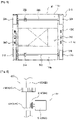
- Figure 8 is a plane view illustrating an operation relationship of an automatic ultrasonic detection device for rails of the present invention while showing a state that a support part is supported as it comes into contact with a welded portion.
- Figure 9 is a view illustrating an operation relationship of an automatic ultrasonic detection device for rails of the present invention while showing a state that a support part is supported as it comes into contact with a welded portion.
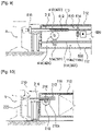
- Figure 10 is a view illustrating an operation relationship of an automatic ultrasonic detection device for rails of the present invention while showing a state that a scan member is drawn to a welding part of a rail.
- the fourth motor 620 of the support part 610 starts operating in a state that it is positioned on the line of the rails R, the screw shaft 612 rotates, and the slide member 616 engaged to both sides of the screw shaft 612 draws toward the outer side of the housing 114, and the guide roller 618 and the ball 62 come into contact with the side portion of the rail R.
- the first and second cooperating gears 413 and 322 engaged with the second and third driven gears 414 and 424 rotate, so the front wheel shaft 312 and the rear wheel shaft 320 rotate.
- the operation direction of the automatic ultrasonic detection device 100 for rails is determined depending on the rotation directions of the third and fourth motors 512 and 522 of the driving force transfer part 510.
- the automatic ultrasonic detection device 100 for rails runs on the lines between the rails R.
- the automatic ultrasonic detection device 100 for rails when the scan part 220 is positioned at the side of the welded portion of the neighboring rails R, the automatic ultrasonic detection device 100 for rails stops.
- ultrasonic waves are emitted, and scan is performed, and the scanned data are transmitted to the central control center through the probe.
- the automatic ultrasonic detection device 100 for rails moves to the next welded portion of the rails R, and starts scanning the welded portion in the same manner as the above.
- the welded portions connecting the neighboring rails R are inspected by the above described repeated operations, and a necessary maintenance work is performed, so the train can run in safe.
- the automatic ultrasonic detection device 100 for rails generally runs at the night time when the trains don't run, and at the day time when the trains run, the automatic ultrasonic detection device 100 for tails remains stopped between the rails R.
- the automatic ultrasonic detection device 100 for rails is configured to generate electricity using solar light when being parked, and the thusly generated electricity is charged in the storage battery 714, and the automatic ultrasonic detection device 100 for rails can run at the night day using the charged electricity so as to inspect the welded portion connecting the neighboring rails R.
- Figure 11 is a view illustrating an automatic ultrasonic detection device for rails according to another embodiment of the present invention.
- the front and rear ends of the body 112 are prolonged, and a slope plate 120 is installed at the top of the prolonged body 112.
- the slope plate 120 is provided at the front and rear ends of the body 112, it is possible to substantially reduce the air resistance generating when the trains pass by in a state that the automatic ultrasonic detection device 100 for rails remains stopped between the rails R, thus preventing the movements of the same, which results in the preventions of part damages.
- the present invention relates to an automatic ultrasonic detection device for rails, and in particular to an automatic ultrasonic detection device for rails which makes it possible to inspect any cracks in a welded portion connecting neighboring rails as it automatically operates along the rails and to maintain a parked state between the rails when the welded portion is not inspected.
Landscapes
- Physics & Mathematics (AREA)
- Health & Medical Sciences (AREA)
- Life Sciences & Earth Sciences (AREA)
- Chemical & Material Sciences (AREA)
- Analytical Chemistry (AREA)
- Biochemistry (AREA)
- General Health & Medical Sciences (AREA)
- General Physics & Mathematics (AREA)
- Immunology (AREA)
- Pathology (AREA)
- Acoustics & Sound (AREA)
- Investigating Or Analyzing Materials By The Use Of Ultrasonic Waves (AREA)
Description
- The present invention relates to an automatic ultrasonic detection device for rails, and in particular to an automatic ultrasonic detection device for rails which makes it possible to inspect any cracks in a welded portion connecting neighboring rails as it automatically operates along the rails and to maintain a parked state between the rails when the welded portion is not inspected.
- The rail for trains is generally manufactured in a long shape by a rolling mill, and the manufactured rail is cut with a length of 20-25m, and the cut rails are installed through a rail installation procedure for the train to run along the rails.
- At this time, when the rails are installed, a plurality of rails are connected by welding the neighboring rails, so the rails can be extended endlessly for the trail to run along the rails.
- When the rains repeatedly run along the rails, cracks may occur at the welded portions connecting the neighboring rails due to repeated stresses.
- So, it is necessary to frequently inspect the cracks in the connection portion connecting the neighboring installed rails, namely, the welded portions for the purpose of checking the cracks. If a cracked portion is inspected, the cracked portion is repaired through a maintenance work for the trains to run in safe.
- In addition, the inspection of the cracks at the welded portions of the rails is generally performed during the nights when the trains don't run.
- As a method for inspecting the welded portions between the rails, a worker rides on a vehicle which runs along the lines and inspects the occurrence of the cracks using a probe at the welded portions while he moves. A known railroad track inspection car is described for example in
US-A-4468966 . Another known railway track inspection apparatus is described inGB-A-2314110 - According to the conventional inspection method in which the cracks at the welded portions are inspected while the worker moves along the rails on an inspection vehicle, the inspection vehicle must be stored in a garage so as not to interfere with the operations of the trains which are scheduled to run at the day time, which consequently makes problems.
- In addition, the cracks are inspected by the worker while he moves along the lines on the inspection vehicle, more workers are needed, and more work time are inevitably consumed.
- Accordingly, the present invention is made to improve the above mentioned problems encountered in the conventional art and other problems. It is an object of the present invention to provide an automatic ultrasonic detection device for rails which has features in that costs for workers can be saved because workers are not needed for the sake of inspections of the cracks of the welded portions connecting neighboring rails in such way to inspect the cracks and transfer data on the cracks while a detection device runs in an unmanned way along the rails installed at each line.
- It is another object of the present invention to provide an automatic ultrasonic detection device for rails which makes it possible not to interfere with the operations of the trains which run along the lines in such a way that the detection device is parked on the rails installed to correspond to the lines when the detection device does not inspect the cracks of the welded portions of the rails.
- It is further another object of the present invention to provide an automatic ultrasonic detection device for rails which makes it possible to inspect the cracks in such a way that an inspection device runs in safe without departing from the lines when inspecting the cracks in the welded portion by providing a support part which is installed at both sides and front and rear sides of a body for the purpose of supporting the inner sides of the rails.
- It is further another object of the present invention to provide an automatic ultrasonic detection device for rails which can operate in safe without any interferences in such a way that a probe part is configured to be contractible from the body and is positioned at a welded portion of the rails, and an ultrasonic fixing member is drawn and inspects the cracks and returns to its original position after finishing the inspections.
- Meanwhile, it is further another object of the present invention to provide an automatic ultrasonic detection device for rails which can operate with the aid of a driving force obtained by way of a self-charging method by providing a solar cell at the top.
- To achieve the above objects, there is provided an automatic ultrasonic detection device for rails, comprising a body part; a wheel part installed at both sides of the body part; an operation part which is installed in the body part and activates the wheel part; and a driving force transfer part transferring a driving force to the operation part.
- Here, the body part comprises a plate shaped body which is spaced apart from the ground; a housing which is installed at the top of the body and is divided by a partition and is formed of first and second installation compartments formed at front and rear ends for installing the operation part and the driving force transfer part, and a third installation compartment formed between the first and second installation compartments for the installation of an ultrasonic probe; and a cover member covering the first, second and third installation compartments of the housing. The body part further comprises a support part supported by the rails. The support part comprises a screw shaft which is provided in each of the first and second installation compartments formed in the housing of the body part, each screw shaft having a first driven gear at its center portion and threads each formed in different directions at both sides about its center portion; a slide member which is thread fixed at both sides of each screw shaft and has a long groove in a longitudinal direction, the housing including a protrusion which is engaged to the long groove; a guide roller which is fixedly engaged at an outer circumferential surface of an end portion of each slide member; and for each screw shaft a first motor to the motor shaft of which is fixedly engaged a driving gear engaged with the first driven gear.
- In addition, in the third installation compartment is provided a scan part scanning a welded portion connecting rails.
- Here, the scan part comprises a guide pipe installed in a pair at both sides of an inner surface of the third installation compartment and having a cut-away hole formed at its lower side; a rack which is engaged at an inner side of the guide pipe and protrudes from the outer side of the housing, and a scan member is provided at an end portion of the rack positioned at the outer side of the housing; and a second motor which is positioned in the cut-away holed formed at the lower side of the guide pipe and has a motor shaft to which a pinion engaged with the rack is fixedly engaged.
- In addition, the wheel part comprises a front wheel shaft which protrudes in both side directions after it passes through the first installation compartment formed in the housing of the body part and has a first cooperating gear for a position in the first installation compartment; a first sprocket segment installed at an end portion of both sides of the front wheel shaft; a rear wheel shaft which protrudes in both side directions after it passes through a second installation compartment formed in the housing of the body part and has a second cooperating gear for an installation in the second installation compartment; a second sprocket segment installed at an end portion of both sides of the rear wheel shaft; and an endless track connecting the first sprocket segment and the second sprocket segment.
- Here, a frame is provided at an outer side portion of each of the first and second sprocket segments, and at the top and lower portions of the frame are provided a plurality of assistant rollers supporting the inner side surfaces of the endless track.
- In addition, the operation part comprises first and second driving shafts which are provided in the first and second installation compartments of the body part as they are perpendicular to the top of each of the front wheel shaft and the rear wheel shaft of the wheel part and which have second and third driven gears engaged with the first and second cooperating gears; and first and second driven bevel gears which are provided at the first and second driving shafts and are spaced apart from the second and third driven gears.
- In addition, the driving force transfer part comprises third and fourth motors which are installed in the first and second installation compartments of the body part; and first and second driving bevel gears which are fixedly engaged to the motor shafts of the third and fourth motors and are engaged with the first and second driven bevel gears provided in the first and second driving shafts of the operation part.
- In addition, a mounting hole is formed at an end portion of the slide member, and an elastic member is mounted in the mounting hole, and a ball is mounted at a front side of the elastic member, and a fixing plate is configured to cover the mounting hole of the slide member and to fixedly engage for the ball to protruded outwards.
- In addition, the body part further comprises a solar power generation part, and the solar power generation part comprises a solar cell plate provided at the top of the cover member provided at the top of the housing of the body; a storage battery which is installed in both the first and second installation compartments of the housing or is installed in either the first installation compartment or the second installation compartment; and a charging module which is installed in both the first and second installation compartments of the housing or is installed in either the first installation compartment or the second installation compartment.
- In addition, the body of the body part is prolonged in forward and backward directions, and a slope plate is installed at the top of the prolonged body.
- The present invention has effects in that costs for workers can be saved because workers are not needed for the sake of inspections of the cracks of the welded portions connecting neighboring rails in such way to inspect the cracks and transfer data on the cracks while a detection device runs in an unmanned way along the rails installed at each line.
- In addition, the present invention makes it possible not to interfere with the operations of the trains which run along the lines in such a way that the detection device is parked on the rails installed to correspond to the lines when the detection device does not inspect the cracks of the welded portions of the rails.
- In addition, the present invention makes it possible to inspect the cracks in such a way that an inspection device runs in safe without departing from the lines when inspecting the cracks in the welded portion by providing a support part which is installed at both sides and front and rear sides of a body for the purpose of supporting the inner sides of the rails.
- In addition, the automatic ultrasonic detection device for rails can operate in safe without any interferences in such a way that a probe part is configured to be contractible from the body and is positioned at a welded portion of the rails, and an ultrasonic fixing member is drawn and inspects the cracks and returns to its original position after finishing the inspections.
- Meanwhile, the automatic ultrasonic detection device for rails can operate with the aid of a driving force obtained by way of a self-charging method by providing a solar cell at the top.
-
-
Figure 1 is a perspective view illustrating an automatic ultrasonic detection device for rails according to the present invention. -
Figure 2 is a cross sectional view illustrating an automatic ultrasonic detection device for rails according to the present invention. -
Figure 3 is a plane view illustrating an automatic ultrasonic detection device for rails according to the present invention. -
Figure 4 is a view illustrating a scan part of the present invention. -
Figure 5 is a view illustrating a wheel part of the present invention. -
Figure 6 is a view illustrating an operation part and a driving force transfer part of the present invention. -
Figure 7 is a view illustrating a support part of the present invention. -
Figure 8 is a plane view illustrating an operation relationship of an automatic ultrasonic detection device for rails of the present invention while showing a state that a support part is supported as it comes into contact with a welded portion. -
Figure 9 is a view illustrating an operation relationship of an automatic ultrasonic detection device for rails of the present invention while showing a state that a support part is supported as it comes into contact with a welded portion. -
Figure 10 is a view illustrating an operation relationship of an automatic ultrasonic detection device for rails of the present invention while showing a state that a scan member is drawn to a welding part of a rail. -
Figure 11 is a view illustrating an automatic ultrasonic detection device for rails according to another embodiment of the present invention. - The automatic ultrasonic detection device for rails will be described according to a preferred embodiment of the present invention with reference to the accompanying drawings.
-
Figure 1 is a perspective view illustrating an automatic ultrasonic detection device for rails according to the present invention.Figure 2 is a cross sectional view illustrating an automatic ultrasonic detection device for rails according to the present invention.Figure 3 is a plane view illustrating an automatic ultrasonic detection device for rails according to the present invention.Figure 4 is a view illustrating a scan part of the present invention.Figure 5 is a view illustrating a wheel part of the present invention.Figure 6 is a view illustrating an operation part and a driving force transfer part of the present invention.Figure 7 is a view illustrating a support part of the present invention. - As shown in
Figures 1 to 7 , the automaticultrasonic detection device 100 for rails according to the present invention comprises abody part 110 spaced apart from the ground. - Here, the
body part 110 comprises a plate-shaped body 112, and a the top of thebody 112 is provided arectangular housing 114. - At this time, the
housing 114 is partitioned into pieces by a plurality of partitions, thus forming first, second andthird installation compartments - There is provided a
cover member 116 covering the tops of the first, second andthird installation compartments housing 114. - At the center portion of the
housing 114, namely, in thethird installation compartment 114c formed between the first andsecond installation compartments - In the
third installation compartment 114c of thehousing 114 is provided ascan part 210 scanning the welded portions connecting neighboring rails R. - Here, the
scan part 210 is provided in such a way to correspond to the inner surface of thethird installation compartment 114c, a cut-awayhole 212a being formed at its lower side, and aguide pipe 212 is fixed at thehousing 114. - At this time, there is provided a
rack 214 which is inserted in the inner side of theguide tube 212, one side of the rack being protruded from the outer side of thehousing 114 and being movably engaged. At the end portion of therack 214 which is protruded from the outer side of thehousing 114 is provided ascan member 220 configured to scan the welded portions connecting the neighboring rails R. - There is further provided a
second motor 218 to the motor shaft of which is engaged apinion 216 engaged with therack 214 by way of the cut-awayhole 212a formed at the lower side of theguide pipe 212. - Therefore, the
pinion 216 fixedly engaged at the motor shaft rotates by the operation of thesecond motor 218, and at the same time therack 214 draws toward the outer side of thehousing 114, and thescan member 220 provided at the end portion of therack 214 approaches the welded portion connecting the neighboring rails R or comes into contact with the same. At the time thescan member 220 comes into contact with the welded portion, ultrasonic waves are emitted, thus scanning the welded portion. - There is provided a
wheel part 310 for the sake of operation as it is installed at both sides of thebody part 110. - Here, the
wheel part 310 comprises afront wheel shaft 312 which passes through thefirst installation compartment 114a of thehousing 114 in the widthwise direction, both sides of the front wheel shaft being exposed to the outside. Thefront wheel shaft 312 comprises a first cooperatinggear 314. - At this time, at the end portions of both sides of the front wheel shaft 313 is provided a
first sprocket segment 316. - In the
second installation compartment 114b of thehousing 114 is provided arear wheel shaft 320 corresponding to thefront wheel shaft 312, and at therear wheel shaft 320 is provided a second cooperatinggear 322, and at the end portions of both sides of therear wheel shaft 320 is provided asecond sprocket segment 324. - At this time, an
endless track 330 connects thefirst sprocket segment 316 and thesecond sprocket segment 324, respectively. - At one side surface of each of the first and
second sprocket segments frame 340 supporting the same, and at the upper and lower sides of theframe 340 are provided a plurality ofassistant rollers 342 supporting the inner side of theendless track 330. - The
operation part 410 is provided in the first andsecond installation compartments housing 114 for the purpose of operating thefront wheel shaft 312 and therear wheel shaft 320. - Here, the
operation part 410 comprises afirst driving shaft 412 which is installed in thefirst installation compartment 114a and is positioned at the top of thefront wheel shaft 312 and is installed perpendicular to thefront wheel shaft 312. At thefirst driving shaft 412 is provided a second drivengear 414 engaged with the first cooperatinggear 314. A second drivengear 414 is fixedly engaged with thefirst driving shaft 412 and is spaced apart from the second drivengear 414. - The
operation part 410 comprises asecond driving shaft 422 which is installed in thesecond installation compartment 114b and is positioned at the top of therear wheel shaft 320 and is installed perpendicular to therear wheel shaft 320. At thesecond driving shaft 422 is provided a third drivengear 424 engaged with the second cooperatinggear 322. A second drivenbevel gear 426 is spaced apart from the third drivengear 424 and is fixedly engaged with thesecond driving shaft 422. - Therefore, as the first and
second driving shafts gears second driving shafts gears 314 and 333 engaged with the second and third drivengears rear wheel shafts ultrasonic detection device 100 for rails moves back and forth. - A driving
transfer part 510 is provided in the first andsecond installation compartments housing 114 of thebody part 110 for transferring driving force for theoperation part 410 to stop. - Here, the driving
force transfer part 510 comprises athird motor 512 which is installed in thefirst installation compartment 114a of thehousing 114 and to which a firstdriving bevel gear 514 engaged with the first drivenbevel gear 414, at the motor shaft of which thefirst driving shaft 412 is provided, is fixedly engaged, for thereby transferring driving force. - In the
second installation compartment 114b of thehousing 114 is installed afourth motor 522 to which a seconddriving bevel gear 524 engaged with the second drivenbevel gear 424, at the motor shaft of which is installed thesecond driving shaft 422, is fixedly engaged, for thereby transferring driving force. - As the third and
fourth motors bevel gears driving bevel gears second driving shafts front wheel shaft 312 and therear wheel shaft 320 rotate by means of the rotations of the first andsecond driving shafts - In the first and
second installation compartment housing 114 is provided asupport part 610 which is supported by the inner side of the rail R for the automaticultrasonic detection device 100 for rails to run in safe. - At this time, the
support part 610 is installed in a pair disposed opposite at both sides of thefirst installation compartment 114a of thehousing 114, and in thesecond installation compartment 114b, it is installed corresponding to thesupport part 610 installed in thefirst installation compartment 114a. - The
support part 610 is provided in each of the first andsecond installation compartments housing 114, and at the center is provided at a third drivengear 614. Thesupport part 610 comprises ascrew shaft 612 with threads being opposite about the center. - A
slide member 616 is thread engaged at both sides of thescrew shaft 612 and is fixedly engaged for itself to protrude to the outside of thehousing 114 and has along groove 616a in an outer circumference direction. - A
protrusion 617 is provided in thehousing 114 for the purpose of preventing rotation of theside member 616 when it slides as it is engaged to thelong groove 616a formed at the outer circumferential surface of theslide member 616. - There is provided a
guide roller 618 which is engaged to an outer circumferential surface of the end portion of the slide member 61 and is supported by the rail R. - There is provided a
first motor 620 at the motor shaft of which is fixedly engaged thedriving gear 622 engaging with the first drivengear 614 provided at the center of thescrew shaft 612. - In the above described constructions, as the
screw shaft 612 rotates upon the operation of thefirst motor 620, the slide member 615 slides, and theslide member 616 is drawn during the operation of the automaticultrasonic detection device 100 for rails, and it runs in a state that theguide roller 618 comes into contact with the rail R and runs in safe with a constant interval from the rail R. - At an end portion of the
slide member 616 is provided a mountinghole 616b, and anelastic member 630 is mounted in the mountinghole 616b, and at a front side of theelastic member 630 is mounted aball 632. - There is provided a
fixing pin 634 which covers the mountinghole 616b of theslide member 616 and is fixed at theslide member 616 by a fixing means such as a bolt, etc. for theball 632 to expose to the outside. - During the operation of the automatic
ultrasonic detection device 100 for rails, theslide member 616 draws from thehousing 114, and as soon as theguide roller 618 comes into contact with the rail R, theball 632 operates as it contacts with the inner side surface of the rail R, so it can run with a certain interval from the rail R, and when passing past the welded portion of the rails R, theball 632 pressurizes theelastic member 630 and inserts the same into the mountinghole 616b. After it passed, it returns to its original position with the aid of theelastic member 630, so theball 632 can always maintain a contact state with the rail R . - In the
body part 110 is provided a solarpower generation part 710 by which is generated an electric power for thereby operating the automaticultrasonic detection device 100 for rails. - The solar
power generation part 710 comprises asolar cell plate 712 generating electric power as solar light is incident on the top of thecover member 116 for thereby generating electric current on the basis of photoelectro motive force. - A
storage battery 714 is provided in both the first andsecond installation compartments housing 114 or in at least of the first andsecond installation compartments - In addition, there is provided a
charging module 716 which has features in that when solar light is incident on thesolar cell plate 712, the current generates on the basis of photoelectro motive force, and when the generating current reaches a storage limit during the charge of thestorage battery 714, it is detected, and the current generating from thesolar cell plate 712 is prevented from inputting in thestorage battery 714. - Therefore, the electric power supplied to the automatic
ultrasonic detection device 100 for rails is used for the sake of self-power generation with solar light and at the same time it is supplied. - The operations of the automatic ultrasonic detection device for rails according to the present invention will be described.
-
Figure 8 is a plane view illustrating an operation relationship of an automatic ultrasonic detection device for rails of the present invention while showing a state that a support part is supported as it comes into contact with a welded portion.Figure 9 is a view illustrating an operation relationship of an automatic ultrasonic detection device for rails of the present invention while showing a state that a support part is supported as it comes into contact with a welded portion.Figure 10 is a view illustrating an operation relationship of an automatic ultrasonic detection device for rails of the present invention while showing a state that a scan member is drawn to a welding part of a rail. - As shown therein, in the automatic
ultrasonic detection device 100 for rails according to the present invention, when thefourth motor 620 of thesupport part 610 starts operating in a state that it is positioned on the line of the rails R, thescrew shaft 612 rotates, and theslide member 616 engaged to both sides of thescrew shaft 612 draws toward the outer side of thehousing 114, and theguide roller 618 and the ball 62 come into contact with the side portion of the rail R. - In this state, when the third and
fourth motors force transfer part 510 provided in the first andsecond installation compartments housing 114 are operated, the first and seconddriving bevel gears fourth motors bevel gears driving bevel gears second driving shafts - As the first and
second shafts gears 413 and 322 engaged with the second and third drivengears front wheel shaft 312 and therear wheel shaft 320 rotate. - As the
front wheel shaft 312 and therear wheel shaft 320 rotate, the first andsecond sprocket segments endless track 330 connecting the first andsecond sprocket segments - At this time, the operation direction of the automatic
ultrasonic detection device 100 for rails is determined depending on the rotation directions of the third andfourth motors force transfer part 510. - Through the above described operations, the automatic
ultrasonic detection device 100 for rails runs on the lines between the rails R. - As the automatic
ultrasonic detection device 100 for rails, when thescan part 220 is positioned at the side of the welded portion of the neighboring rails R, the automaticultrasonic detection device 100 for rails stops. - After the automatic
ultrasonic detection device 100 for rails stops, when thefirst motor 218 of thescan part 210 provided in thethird installation compartment 114c of thehousing 114 is activated, thepinion 216 fixedly engaged to the motor shaft of thesecond motor 218 rotates, and therack 214 is drawn to the outside of thehousing 114, so thescan member 220 approaches and comes into contact with the welded portion of the rails R, - After the
scan part 220 is positioned close to the welded portion of the rails R, ultrasonic waves are emitted, and scan is performed, and the scanned data are transmitted to the central control center through the probe. - The method for emitting ultrasonic waves to the welded portion of the rails R and scanning it and the method for transmitting the scanned data to the central control center are known arts, so the detailed descriptions thereof will be omitted.
- After the scan work on the welded portion of the rails R is finished, when the
second motor 218 is operated in the reverse direction, thepinion 216 rotates in the reverse direction, and therack 214 is forced to insert in the inner side of thehousing 114, so thescan member 220 departs from the welded portion of the rails R. - In this state, the automatic
ultrasonic detection device 100 for rails moves to the next welded portion of the rails R, and starts scanning the welded portion in the same manner as the above. - The welded portions connecting the neighboring rails R are inspected by the above described repeated operations, and a necessary maintenance work is performed, so the train can run in safe.
- The automatic
ultrasonic detection device 100 for rails generally runs at the night time when the trains don't run, and at the day time when the trains run, the automaticultrasonic detection device 100 for tails remains stopped between the rails R. - At this time, in a state that the automatic
ultrasonic detection device 100 for rails is stopped between the rails R, a safely fixed state is obtained, so the automaticultrasonic detection device 100 for rails does not agitate from the strong air generating when the train passes by. - In addition, the automatic
ultrasonic detection device 100 for rails is configured to generate electricity using solar light when being parked, and the thusly generated electricity is charged in thestorage battery 714, and the automaticultrasonic detection device 100 for rails can run at the night day using the charged electricity so as to inspect the welded portion connecting the neighboring rails R. -
Figure 11 is a view illustrating an automatic ultrasonic detection device for rails according to another embodiment of the present invention. - As shown therein, the front and rear ends of the
body 112 are prolonged, and a slope plate 120 is installed at the top of theprolonged body 112. - The operations of the automatic ultrasonic detection device for rails according to the present invention are same as the earlier described operations, so the descriptions thereof will be omitted.
- However, since the slope plate 120 is provided at the front and rear ends of the
body 112, it is possible to substantially reduce the air resistance generating when the trains pass by in a state that the automaticultrasonic detection device 100 for rails remains stopped between the rails R, thus preventing the movements of the same, which results in the preventions of part damages. - As the present invention may be embodied in several forms without departing from the essential characteristics thereof, it should also be understood that the above-described examples are not limited by any of the details of the foregoing description, unless otherwise specified, but rather should be construed broadly within its scope as defined in the appended claims, and therefore all changes and modifications that fall within the meets and bounds of the claims are therefore intended to be embraced by the appended claims
- The present invention relates to an automatic ultrasonic detection device for rails, and in particular to an automatic ultrasonic detection device for rails which makes it possible to inspect any cracks in a welded portion connecting neighboring rails as it automatically operates along the rails and to maintain a parked state between the rails when the welded portion is not inspected.
Claims (10)
- An automatic ultrasonic detection device (100) for rails, comprising:a body part (110);a wheel part (310) installed at both sides of the body part (110);an operation part (410) which is installed in the body part (110) and activates the wheel part (310); anda driving force transfer part (510) transferring a driving force to the operation part (410);characterized in that the automatic ultrasonic detection device (100) comprises:a plate shaped body (112) which is spaced apart from the ground;a housing (114) which is installed at the top of the body (112) and is divided by a partition and is formed of first and second installation compartments (114a, 114b) formed at front and rear ends for installing the operation part (410) and the driving force transfer part (510), and a third installation compartment (114c) formed between the first and second installation compartments (114a, 114b);an ultrasonic probe installed in said third installation compartment (114c);a cover member (116) covering the first, second and third installation compartments (114a, 114b, 114c) of the housing (114);the body part (110) further comprising a support part (610) supported by the rails, wherein the support part (610) comprises:a screw shaft (612) which is provided in each of the first and second installation compartments (114a, 114b) formed in the housing (114) of the body part (110), each screw shaft (612) having a first driven gear (614) at its center portion and threads each formed in different directions at both sides about its center portion;a slide member (616) which is thread fixed at both sides of each screw shaft (612) and has a long groove (616a) in a longitudinal direction, the housing (114) including a protrusion (617) which is engaged to the long groove (616a);a guide roller (618) which is fixedly engaged at an outer circumferential surface of an end portion of each slide member 616; and for each screw shaft (612) a first motor (620) to the motor shaft of which is fixedly engaged a driving gear (622) engaged with the first driven gear (614).
- The device of claim 1, where in the third installation compartment (114c) is provided a scan part (210) scanning a welded portion connecting rails.
- The device of claim 2, wherein the scan part (210) comprises:a guide pipe (212) installed in a pair at both sides of an inner surface of the third installation compartment (114c) and having a cut-away hole (212a) formed at its lower side;a rack (214) which is engaged at an inner side of the guide pipe (212) and protrudes from the outer side of the housing (114), and a scan member (220) is provided at an end portion of the rack (214) positioned at the outer side of the housing (114); anda second motor (218) which is positioned in the cut-away hole (212a) formed at the lower side of the guide pipe (212) and has a motor shaft to which a pinion (216) engaged with the rack (214) is fixedly engaged.
- The device of claim 1, wherein the wheel part (310) comprises:a front wheel shaft (312) which protrudes in both side directions after it passes through the first installation compartment (114a) formed in the housing (114) of the body part (110) and has a first cooperating gear (314) for a position in the first installation compartment (114a);a first sprocket segment (316) installed at an end portion of both sides of the front wheel shaft (312);a rear wheel shaft (320) which protrudes in both side directions after it passes through a second installation compartment (114b) formed in the housing (114) of the body part (110) and has a second cooperating gear (322) for an installation in the second installation compartment (114b);a second sprocket segment (324) installed at an end portion of both sides of the rear wheel shaft (320); andan endless track (330) connecting the first sprocket segment (316) and the second sprocket segment (324).
- The device of claim 4, wherein a frame (340) is provided at an outer side portion of each of the first and second sprocket segments (316, 324), and at the top and lower portions of the frame (340) are provided a plurality of assistant rollers (342) supporting the inner side surfaces of the endless track (330).
- The device of claim 1, wherein the operation part (410) comprises:first and second driving shafts (412, 422) which are provided in the first and second installation compartments (114a, 114b) of the body part (110) as they are perpendicular to the top of each of the front wheel shaft (312) and the rear wheel shaft (320) of the wheel part (310) and which have second and third driven gears (414, 424) engaged with the first and second cooperating gears (314, 322); andfirst and second driven bevel gears (416, 426) which are provided at the first and second driving shafts (412, 422) and are spaced apart from the second and third driven gears (414, 424).
- The device of claim 1, wherein the driving force transfer part (510) comprises:third and fourth motors (512, 522) which are installed in the first and second installation compartments (114a, 114b) of the body part (110); andfirst and second driving bevel gears (514, 524) which are fixedly engaged to the motor shafts of the third and fourth motors (512, 522) and are engaged with the first and second driven bevel gears (416, 426) provided in the first and second driving shafts (412, 422) of the operation part (410).
- The device of claim 1, wherein a mounting hole (616b) is formed at an end portion of the slide member (616), and an elastic member (630) is mounted in the mounting hole (616b), and a ball (632) is mounted at a front side of the elastic member (630), and a fixing plate (634) is configured to cover the mounting hole (616b) of the slide member (616) and to fixedly engage for the ball (632) to protruded outwards.
- The device of claim 8, wherein the body part (110) further comprises a solar power generation part (710), and the solar power generation part (710) comprises:a solar cell plate (712) provided at the top of the cover member (116) provided at the top of the housing (114) of the body part (110);a storage battery (714) which is installed in both the first and second installation compartments (114a, 114b) of the housing (114) or is installed in either the first installation compartment (114a) or the second installation compartment (114b); anda charging module (716) which is installed in both the first and second installation compartments (114a, 114b) of the housing (114) or is installed in either the first installation compartment (114a) or the second installation compartment (114b).
- The device of claim 1, wherein the body (112) of the body part (110) is prolonged in forward and backward directions, and a slope plate (120) is installed at the top of the prolonged body (112).
Applications Claiming Priority (2)
| Application Number | Priority Date | Filing Date | Title |
|---|---|---|---|
| KR1020100115112A KR101196826B1 (en) | 2010-11-18 | 2010-11-18 | A automatic supersonic detection device for railroad rail |
| PCT/KR2010/009171 WO2012067302A1 (en) | 2010-11-18 | 2010-12-21 | Automatic ultrasonic detection device for rails |
Publications (3)
| Publication Number | Publication Date |
|---|---|
| EP2642284A1 EP2642284A1 (en) | 2013-09-25 |
| EP2642284A4 EP2642284A4 (en) | 2018-01-10 |
| EP2642284B1 true EP2642284B1 (en) | 2022-10-26 |
Family
ID=46084204
Family Applications (1)
| Application Number | Title | Priority Date | Filing Date |
|---|---|---|---|
| EP10859711.3A Active EP2642284B1 (en) | 2010-11-18 | 2010-12-21 | Automatic ultrasonic detection device for rails |
Country Status (4)
| Country | Link |
|---|---|
| EP (1) | EP2642284B1 (en) |
| KR (1) | KR101196826B1 (en) |
| ES (1) | ES2932982T3 (en) |
| WO (1) | WO2012067302A1 (en) |
Families Citing this family (9)
| Publication number | Priority date | Publication date | Assignee | Title |
|---|---|---|---|---|
| CN104155363B (en) * | 2014-08-11 | 2017-01-18 | 绵阳创智机电科技有限公司 | Multifunctional rail welding line flaw detection scanning device |
| KR101499477B1 (en) * | 2014-10-31 | 2015-03-18 | 대한검사기술(주) | A automatic ultrasonic scanner |
| WO2018152569A1 (en) * | 2017-02-22 | 2018-08-30 | Rodney Friend | Methods and instrumentation for detection of transverse rolling contact fatigue rail defects within head-hardened rail |
| CN108680588A (en) * | 2018-05-14 | 2018-10-19 | 合肥聚能电物理高技术开发有限公司 | CFETR vacuum chamber beforehand research part longitudinal seam automatic flaw detection positioning devices |
| CN111693607A (en) * | 2020-06-09 | 2020-09-22 | 湖南铁道职业技术学院 | Device suitable for railway rails automated inspection |
| CN112903825A (en) * | 2021-01-19 | 2021-06-04 | 昆明论道机械制造有限公司 | Detection equipment capable of rapidly detecting rail surface cracks and detection method thereof |
| CN114034773B (en) * | 2021-11-02 | 2022-06-10 | 嘉兴市磁海无损检测设备制造有限公司 | Workpiece flaw detection device capable of intelligently tracing data and flaw detection method thereof |
| JP7655284B2 (en) * | 2022-07-15 | 2025-04-02 | Jfeスチール株式会社 | Rail flaw detection equipment |
| CN116087219B (en) * | 2023-03-06 | 2023-06-13 | 长沙方圆回转支承有限公司 | Slewing bearing flaw detection device |
Family Cites Families (11)
| Publication number | Priority date | Publication date | Assignee | Title |
|---|---|---|---|---|
| US4468966A (en) * | 1982-09-01 | 1984-09-04 | Jackson Jordan, Inc. | Railroad track inspection car |
| JP3217192B2 (en) * | 1993-07-05 | 2001-10-09 | 太平工業株式会社 | Rail flaw detector |
| JPH0989848A (en) * | 1995-09-26 | 1997-04-04 | Hokkaido Riyokaku Tetsudo Kk | Ultrasonic rail inspection system |
| GB9612198D0 (en) * | 1996-06-11 | 1996-08-14 | Bicc Plc | Railway track inspection car |
| CH690851A5 (en) | 1996-11-25 | 2001-02-15 | Speno Internat S A | Apparatus for measuring internal defects of a rail by ultrasound. |
| JP4041566B2 (en) * | 1997-11-10 | 2008-01-30 | 株式会社トキメック | Orbit inspection device |
| JP3665920B2 (en) | 1998-01-06 | 2005-06-29 | バブコック日立株式会社 | Remote nondestructive inspection equipment |
| JP2006017480A (en) * | 2004-06-30 | 2006-01-19 | Sumitomo Metal Ind Ltd | Trackless steel pipe inspection system |
| KR100698546B1 (en) | 2005-10-24 | 2007-03-22 | 한국철도공사 | Rail broken position check device |
| KR100904120B1 (en) * | 2007-11-06 | 2009-06-24 | 현대제철 주식회사 | Rail test equipment for railway |
| EP2096433A1 (en) * | 2008-02-26 | 2009-09-02 | Siemens Aktiengesellschaft | Device for non-destructive materials testing of a test specimen with ultrasonic waves |
-
2010
- 2010-11-18 KR KR1020100115112A patent/KR101196826B1/en not_active Expired - Fee Related
- 2010-12-21 WO PCT/KR2010/009171 patent/WO2012067302A1/en not_active Ceased
- 2010-12-21 EP EP10859711.3A patent/EP2642284B1/en active Active
- 2010-12-21 ES ES10859711T patent/ES2932982T3/en active Active
Also Published As
| Publication number | Publication date |
|---|---|
| KR101196826B1 (en) | 2012-11-01 |
| WO2012067302A1 (en) | 2012-05-24 |
| KR20120053805A (en) | 2012-05-29 |
| EP2642284A4 (en) | 2018-01-10 |
| ES2932982T3 (en) | 2023-01-30 |
| EP2642284A1 (en) | 2013-09-25 |
Similar Documents
| Publication | Publication Date | Title |
|---|---|---|
| EP2642284A1 (en) | Automatic ultrasonic detection device for rails | |
| CN107617616B (en) | Cleaning device and photovoltaic array | |
| CN205762538U (en) | Cleaning device and photovoltaic array | |
| CN108321866B (en) | Autonomous charging device for mobile robot | |
| CN113092494B (en) | Inspection robot and intelligent detection method for train tunnel structure diseases | |
| CN211034131U (en) | Roller butt-joint type automatic guide transport vehicle | |
| US11465653B2 (en) | Unmanned rail vehicle | |
| KR102020116B1 (en) | Guide device for moving of charging cable and electric vehicle charging system comprising the same | |
| CN110549997B (en) | Clean system is changed to power station battery | |
| CN104791579A (en) | Pipeline robot | |
| CN108301658A (en) | A kind of composite type stereo garage | |
| KR101241305B1 (en) | Device for bridge inspection moving type | |
| DE102008005552A1 (en) | Battery change station | |
| KR101447653B1 (en) | Access device for electric vehicle charging | |
| KR20120094251A (en) | Railroad for tube transporting system | |
| CN216299279U (en) | Robot reverse hanging type guide rail | |
| KR101837200B1 (en) | Guide way type electric charging system | |
| CN205387129U (en) | Steel wire cable says driving | |
| CN216783521U (en) | Steel rail flaw detection assembly and steel rail flaw detection vehicle | |
| CN208939894U (en) | A system device for automatic cross-line photovoltaic panel cleaning and defect detection | |
| JP2017149262A (en) | Omniwheel assembly, inspection device, and inspection system | |
| CN114152625B (en) | Deformation and leakage monitoring device for subway tunnel | |
| EP3766723A1 (en) | Charging unit and battery-change station | |
| CN215057905U (en) | Tower barrel convenient to transport and strong in wind resistance for wind power generation | |
| CN224145919U (en) | Electricity-exchanging positioning device and electricity-exchanging system |
Legal Events
| Date | Code | Title | Description |
|---|---|---|---|
| PUAI | Public reference made under article 153(3) epc to a published international application that has entered the european phase |
Free format text: ORIGINAL CODE: 0009012 |
|
| 17P | Request for examination filed |
Effective date: 20130524 |
|
| AK | Designated contracting states |
Kind code of ref document: A1 Designated state(s): AL AT BE BG CH CY CZ DE DK EE ES FI FR GB GR HR HU IE IS IT LI LT LU LV MC MK MT NL NO PL PT RO RS SE SI SK SM TR |
|
| DAX | Request for extension of the european patent (deleted) | ||
| RA4 | Supplementary search report drawn up and despatched (corrected) |
Effective date: 20171212 |
|
| RIC1 | Information provided on ipc code assigned before grant |
Ipc: G01N 29/04 20060101ALI20171206BHEP Ipc: G01N 29/22 20060101ALI20171206BHEP Ipc: G01N 29/265 20060101ALI20171206BHEP Ipc: G01N 29/09 20060101AFI20171206BHEP |
|
| STAA | Information on the status of an ep patent application or granted ep patent |
Free format text: STATUS: EXAMINATION IS IN PROGRESS |
|
| 17Q | First examination report despatched |
Effective date: 20210528 |
|
| GRAP | Despatch of communication of intention to grant a patent |
Free format text: ORIGINAL CODE: EPIDOSNIGR1 |
|
| STAA | Information on the status of an ep patent application or granted ep patent |
Free format text: STATUS: GRANT OF PATENT IS INTENDED |
|
| INTG | Intention to grant announced |
Effective date: 20220511 |
|
| GRAS | Grant fee paid |
Free format text: ORIGINAL CODE: EPIDOSNIGR3 |
|
| GRAA | (expected) grant |
Free format text: ORIGINAL CODE: 0009210 |
|
| STAA | Information on the status of an ep patent application or granted ep patent |
Free format text: STATUS: THE PATENT HAS BEEN GRANTED |
|
| RIN1 | Information on inventor provided before grant (corrected) |
Inventor name: JOYCE, ROB, DWYER Inventor name: SEO, SUNG-IL Inventor name: KWON, TAE-SOO Inventor name: MUN, HYUNG-SUK |
|
| AK | Designated contracting states |
Kind code of ref document: B1 Designated state(s): AL AT BE BG CH CY CZ DE DK EE ES FI FR GB GR HR HU IE IS IT LI LT LU LV MC MK MT NL NO PL PT RO RS SE SI SK SM TR |
|
| REG | Reference to a national code |
Ref country code: GB Ref legal event code: FG4D |
|
| REG | Reference to a national code |
Ref country code: CH Ref legal event code: EP |
|
| REG | Reference to a national code |
Ref country code: AT Ref legal event code: REF Ref document number: 1527371 Country of ref document: AT Kind code of ref document: T Effective date: 20221115 |
|
| REG | Reference to a national code |
Ref country code: DE Ref legal event code: R096 Ref document number: 602010068538 Country of ref document: DE |
|
| REG | Reference to a national code |
Ref country code: IE Ref legal event code: FG4D |
|
| REG | Reference to a national code |
Ref country code: ES Ref legal event code: FG2A Ref document number: 2932982 Country of ref document: ES Kind code of ref document: T3 Effective date: 20230130 |
|
| REG | Reference to a national code |
Ref country code: LT Ref legal event code: MG9D |
|
| REG | Reference to a national code |
Ref country code: NL Ref legal event code: MP Effective date: 20221026 |
|
| REG | Reference to a national code |
Ref country code: AT Ref legal event code: MK05 Ref document number: 1527371 Country of ref document: AT Kind code of ref document: T Effective date: 20221026 |
|
| PG25 | Lapsed in a contracting state [announced via postgrant information from national office to epo] |
Ref country code: NL Free format text: LAPSE BECAUSE OF FAILURE TO SUBMIT A TRANSLATION OF THE DESCRIPTION OR TO PAY THE FEE WITHIN THE PRESCRIBED TIME-LIMIT Effective date: 20221026 |
|
| PG25 | Lapsed in a contracting state [announced via postgrant information from national office to epo] |
Ref country code: SE Free format text: LAPSE BECAUSE OF FAILURE TO SUBMIT A TRANSLATION OF THE DESCRIPTION OR TO PAY THE FEE WITHIN THE PRESCRIBED TIME-LIMIT Effective date: 20221026 Ref country code: PT Free format text: LAPSE BECAUSE OF FAILURE TO SUBMIT A TRANSLATION OF THE DESCRIPTION OR TO PAY THE FEE WITHIN THE PRESCRIBED TIME-LIMIT Effective date: 20230227 Ref country code: NO Free format text: LAPSE BECAUSE OF FAILURE TO SUBMIT A TRANSLATION OF THE DESCRIPTION OR TO PAY THE FEE WITHIN THE PRESCRIBED TIME-LIMIT Effective date: 20230126 Ref country code: LT Free format text: LAPSE BECAUSE OF FAILURE TO SUBMIT A TRANSLATION OF THE DESCRIPTION OR TO PAY THE FEE WITHIN THE PRESCRIBED TIME-LIMIT Effective date: 20221026 Ref country code: FI Free format text: LAPSE BECAUSE OF FAILURE TO SUBMIT A TRANSLATION OF THE DESCRIPTION OR TO PAY THE FEE WITHIN THE PRESCRIBED TIME-LIMIT Effective date: 20221026 Ref country code: AT Free format text: LAPSE BECAUSE OF FAILURE TO SUBMIT A TRANSLATION OF THE DESCRIPTION OR TO PAY THE FEE WITHIN THE PRESCRIBED TIME-LIMIT Effective date: 20221026 |
|
| PG25 | Lapsed in a contracting state [announced via postgrant information from national office to epo] |
Ref country code: RS Free format text: LAPSE BECAUSE OF FAILURE TO SUBMIT A TRANSLATION OF THE DESCRIPTION OR TO PAY THE FEE WITHIN THE PRESCRIBED TIME-LIMIT Effective date: 20221026 Ref country code: PL Free format text: LAPSE BECAUSE OF FAILURE TO SUBMIT A TRANSLATION OF THE DESCRIPTION OR TO PAY THE FEE WITHIN THE PRESCRIBED TIME-LIMIT Effective date: 20221026 Ref country code: LV Free format text: LAPSE BECAUSE OF FAILURE TO SUBMIT A TRANSLATION OF THE DESCRIPTION OR TO PAY THE FEE WITHIN THE PRESCRIBED TIME-LIMIT Effective date: 20221026 Ref country code: IS Free format text: LAPSE BECAUSE OF FAILURE TO SUBMIT A TRANSLATION OF THE DESCRIPTION OR TO PAY THE FEE WITHIN THE PRESCRIBED TIME-LIMIT Effective date: 20230226 Ref country code: HR Free format text: LAPSE BECAUSE OF FAILURE TO SUBMIT A TRANSLATION OF THE DESCRIPTION OR TO PAY THE FEE WITHIN THE PRESCRIBED TIME-LIMIT Effective date: 20221026 Ref country code: GR Free format text: LAPSE BECAUSE OF FAILURE TO SUBMIT A TRANSLATION OF THE DESCRIPTION OR TO PAY THE FEE WITHIN THE PRESCRIBED TIME-LIMIT Effective date: 20230127 |
|
| REG | Reference to a national code |
Ref country code: DE Ref legal event code: R097 Ref document number: 602010068538 Country of ref document: DE |
|
| PG25 | Lapsed in a contracting state [announced via postgrant information from national office to epo] |
Ref country code: SM Free format text: LAPSE BECAUSE OF FAILURE TO SUBMIT A TRANSLATION OF THE DESCRIPTION OR TO PAY THE FEE WITHIN THE PRESCRIBED TIME-LIMIT Effective date: 20221026 Ref country code: RO Free format text: LAPSE BECAUSE OF FAILURE TO SUBMIT A TRANSLATION OF THE DESCRIPTION OR TO PAY THE FEE WITHIN THE PRESCRIBED TIME-LIMIT Effective date: 20221026 Ref country code: EE Free format text: LAPSE BECAUSE OF FAILURE TO SUBMIT A TRANSLATION OF THE DESCRIPTION OR TO PAY THE FEE WITHIN THE PRESCRIBED TIME-LIMIT Effective date: 20221026 Ref country code: DK Free format text: LAPSE BECAUSE OF FAILURE TO SUBMIT A TRANSLATION OF THE DESCRIPTION OR TO PAY THE FEE WITHIN THE PRESCRIBED TIME-LIMIT Effective date: 20221026 Ref country code: CZ Free format text: LAPSE BECAUSE OF FAILURE TO SUBMIT A TRANSLATION OF THE DESCRIPTION OR TO PAY THE FEE WITHIN THE PRESCRIBED TIME-LIMIT Effective date: 20221026 |
|
| REG | Reference to a national code |
Ref country code: CH Ref legal event code: PL |
|
| REG | Reference to a national code |
Ref country code: BE Ref legal event code: MM Effective date: 20221231 |
|
| PG25 | Lapsed in a contracting state [announced via postgrant information from national office to epo] |
Ref country code: SK Free format text: LAPSE BECAUSE OF FAILURE TO SUBMIT A TRANSLATION OF THE DESCRIPTION OR TO PAY THE FEE WITHIN THE PRESCRIBED TIME-LIMIT Effective date: 20221026 Ref country code: LU Free format text: LAPSE BECAUSE OF NON-PAYMENT OF DUE FEES Effective date: 20221221 Ref country code: AL Free format text: LAPSE BECAUSE OF FAILURE TO SUBMIT A TRANSLATION OF THE DESCRIPTION OR TO PAY THE FEE WITHIN THE PRESCRIBED TIME-LIMIT Effective date: 20221026 |
|
| PLBE | No opposition filed within time limit |
Free format text: ORIGINAL CODE: 0009261 |
|
| STAA | Information on the status of an ep patent application or granted ep patent |
Free format text: STATUS: NO OPPOSITION FILED WITHIN TIME LIMIT |
|
| GBPC | Gb: european patent ceased through non-payment of renewal fee |
Effective date: 20230126 |
|
| 26N | No opposition filed |
Effective date: 20230727 |
|
| PG25 | Lapsed in a contracting state [announced via postgrant information from national office to epo] |
Ref country code: LI Free format text: LAPSE BECAUSE OF NON-PAYMENT OF DUE FEES Effective date: 20221231 Ref country code: IE Free format text: LAPSE BECAUSE OF NON-PAYMENT OF DUE FEES Effective date: 20221221 Ref country code: GB Free format text: LAPSE BECAUSE OF NON-PAYMENT OF DUE FEES Effective date: 20230126 Ref country code: CH Free format text: LAPSE BECAUSE OF NON-PAYMENT OF DUE FEES Effective date: 20221231 |
|
| PG25 | Lapsed in a contracting state [announced via postgrant information from national office to epo] |
Ref country code: SI Free format text: LAPSE BECAUSE OF FAILURE TO SUBMIT A TRANSLATION OF THE DESCRIPTION OR TO PAY THE FEE WITHIN THE PRESCRIBED TIME-LIMIT Effective date: 20221026 Ref country code: BE Free format text: LAPSE BECAUSE OF NON-PAYMENT OF DUE FEES Effective date: 20221231 |
|
| PG25 | Lapsed in a contracting state [announced via postgrant information from national office to epo] |
Ref country code: HU Free format text: LAPSE BECAUSE OF FAILURE TO SUBMIT A TRANSLATION OF THE DESCRIPTION OR TO PAY THE FEE WITHIN THE PRESCRIBED TIME-LIMIT; INVALID AB INITIO Effective date: 20101221 |
|
| PG25 | Lapsed in a contracting state [announced via postgrant information from national office to epo] |
Ref country code: CY Free format text: LAPSE BECAUSE OF FAILURE TO SUBMIT A TRANSLATION OF THE DESCRIPTION OR TO PAY THE FEE WITHIN THE PRESCRIBED TIME-LIMIT Effective date: 20221026 |
|
| PG25 | Lapsed in a contracting state [announced via postgrant information from national office to epo] |
Ref country code: MK Free format text: LAPSE BECAUSE OF FAILURE TO SUBMIT A TRANSLATION OF THE DESCRIPTION OR TO PAY THE FEE WITHIN THE PRESCRIBED TIME-LIMIT Effective date: 20221026 Ref country code: IT Free format text: LAPSE BECAUSE OF FAILURE TO SUBMIT A TRANSLATION OF THE DESCRIPTION OR TO PAY THE FEE WITHIN THE PRESCRIBED TIME-LIMIT Effective date: 20221026 |
|
| PG25 | Lapsed in a contracting state [announced via postgrant information from national office to epo] |
Ref country code: MC Free format text: LAPSE BECAUSE OF FAILURE TO SUBMIT A TRANSLATION OF THE DESCRIPTION OR TO PAY THE FEE WITHIN THE PRESCRIBED TIME-LIMIT Effective date: 20221026 |
|
| PG25 | Lapsed in a contracting state [announced via postgrant information from national office to epo] |
Ref country code: TR Free format text: LAPSE BECAUSE OF FAILURE TO SUBMIT A TRANSLATION OF THE DESCRIPTION OR TO PAY THE FEE WITHIN THE PRESCRIBED TIME-LIMIT Effective date: 20221026 Ref country code: MC Free format text: LAPSE BECAUSE OF FAILURE TO SUBMIT A TRANSLATION OF THE DESCRIPTION OR TO PAY THE FEE WITHIN THE PRESCRIBED TIME-LIMIT Effective date: 20221026 |
|
| PG25 | Lapsed in a contracting state [announced via postgrant information from national office to epo] |
Ref country code: BG Free format text: LAPSE BECAUSE OF FAILURE TO SUBMIT A TRANSLATION OF THE DESCRIPTION OR TO PAY THE FEE WITHIN THE PRESCRIBED TIME-LIMIT Effective date: 20221026 |
|
| PG25 | Lapsed in a contracting state [announced via postgrant information from national office to epo] |
Ref country code: MT Free format text: LAPSE BECAUSE OF FAILURE TO SUBMIT A TRANSLATION OF THE DESCRIPTION OR TO PAY THE FEE WITHIN THE PRESCRIBED TIME-LIMIT Effective date: 20221026 |
|
| PGFP | Annual fee paid to national office [announced via postgrant information from national office to epo] |
Ref country code: DE Payment date: 20241029 Year of fee payment: 15 |
|
| PGFP | Annual fee paid to national office [announced via postgrant information from national office to epo] |
Ref country code: FR Payment date: 20241008 Year of fee payment: 15 |
|
| PGFP | Annual fee paid to national office [announced via postgrant information from national office to epo] |
Ref country code: ES Payment date: 20250115 Year of fee payment: 15 |