EP2642226A2 - Refrigeration appliance, in particular for household use, comprising a beverage dispensing device - Google Patents
Refrigeration appliance, in particular for household use, comprising a beverage dispensing device Download PDFInfo
- Publication number
- EP2642226A2 EP2642226A2 EP13158667.9A EP13158667A EP2642226A2 EP 2642226 A2 EP2642226 A2 EP 2642226A2 EP 13158667 A EP13158667 A EP 13158667A EP 2642226 A2 EP2642226 A2 EP 2642226A2
- Authority
- EP
- European Patent Office
- Prior art keywords
- refrigeration appliance
- valve
- actuator element
- beverage
- coupling
- Prior art date
- Legal status (The legal status is an assumption and is not a legal conclusion. Google has not performed a legal analysis and makes no representation as to the accuracy of the status listed.)
- Granted
Links
Images


Classifications
-
- F—MECHANICAL ENGINEERING; LIGHTING; HEATING; WEAPONS; BLASTING
- F25—REFRIGERATION OR COOLING; COMBINED HEATING AND REFRIGERATION SYSTEMS; HEAT PUMP SYSTEMS; MANUFACTURE OR STORAGE OF ICE; LIQUEFACTION SOLIDIFICATION OF GASES
- F25D—REFRIGERATORS; COLD ROOMS; ICE-BOXES; COOLING OR FREEZING APPARATUS NOT OTHERWISE PROVIDED FOR
- F25D23/00—General constructional features
- F25D23/12—Arrangements of compartments additional to cooling compartments; Combinations of refrigerators with other equipment, e.g. stove
- F25D23/126—Water cooler
Definitions
- the present invention relates to a refrigeration appliance, in particular for household use, comprising a beverage dispensing device according to the preamble of claim 1.
- the present invention also relates to an associated beverage dispensing device.
- a refrigeration appliance in particular for household use, of the type comprising a structure with at least one compartment formed therein for food preservation.
- Refrigeration appliances known in the art typically comprise two compartments which are kept at different temperatures, thus providing at least two different food preservation states, in particular a refrigerator compartment suitable for preserving fresh food at a temperature between 0°C and 10°C and a freezer compartment suitable for preserving frozen food at a temperature between -15°C and -30°C; such refrigeration appliances are commonly referred to by those skilled in the art of household refrigeration as “double-door” or “combined” refrigerators, depending on the relative position of the two compartments.
- double-door refrigeration appliance
- the freezer compartment is arranged above the refrigerator compartment, whereas in a “combined” refrigeration appliance the freezer compartment is located at the bottom.
- a refrigeration appliance in particular for household use, may include a device for dispensing a beverage outside said refrigeration appliance.
- Refrigeration appliances with such features have been common for decades in the USA; actually, the refrigeration appliances widespread on the American market are equipped with beverage dispensing devices capable of dispensing not only refrigerated water, but also ice and, in some cases, refrigerated soft drinks.
- said beverage dispensing device comprises:
- valve is so positioned as to protrude both inside and outside the refrigeration appliance, and said actuator element is operated from the outside of the refrigeration appliance by a user wanting the beverage to exit the valve.
- valve is associated (whether directly or indirectly, e.g. by means of suitable ducts) with a reservoir located inside a compartment of the refrigeration appliance, in particular said reservoir being typically positioned in a refrigerator compartment; it is however clear that the valve may also be associated (in this case as well, either directly or indirectly, e.g. by means of suitable ducts or pipes) with the water main.
- a recess is usually present where the beverage dispensing valve or the ducts associated therewith come out; in said recess, the user can insert and/or lay a container suitable for receiving the dispensed beverage, e.g. a glass.
- the refrigeration appliances known in the art are designed in a manner such that securing the actuator element associated with the valve into the structure, in particular into the door structure, is an extremely difficult task.
- said actuator element must be hinged to the structure or to the door of the refrigeration appliance in the proximity of the valve, so that the latter can be operated in order to dispense the beverage; it is apparent that, for the valve to be operated correctly, these operations must be carried out with great precision and accuracy.
- the actuator element can only be mounted to the structure or door of the refrigeration appliance and can only be properly positioned in the proximity of the valve by using a special tool; it is apparent that this contributes to increasing the difficulties and costs incurred for manufacturing prior-art refrigeration appliances.
- a refrigeration appliance in particular for household use, which comprises a beverage dispensing device, and an associated beverage dispensing device, which are adapted to overcome the above-described drawbacks , thus proving particularly efficient and economical.
- the present invention provides a refrigeration appliance, in particular for household use, which comprises a beverage dispensing device, and an associated beverage dispensing device, which incorporate the features set out in the appended claims, which are intended to be an integral part of the present description.
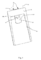
- FIG. 1 shows a schematic sectional view of a refrigeration appliance, in particular for household use, in accordance with the present invention, designated as a whole by reference numeral 1.
- Said refrigeration appliance 1 comprises a structure 2 with at least one compartment 3, 4 formed therein for food preservation, said structure 2 comprising at least one door 3P, 4P for closing said at least one compartment 3, 4.
- the structure 2 generally referred to herein is meant to also include at least one door 3P, 4P, since said at least one door 3P, 4P is a part of the structure 2.
- said at least one compartment 3, 4 comprises:
- the refrigeration appliance 1 shown in Fig. 1 is a "combined" one, in that the freezer compartment 4 is located under the refrigerator compartment 3; it is however clear that the refrigeration appliance 1 according to the present invention may be of a different type as well.
- Fig. 1 shows rather thick walls of the structure 2, to indicate the presence of a layer of thermally insulating material; normally, the thickness of the insulating material depends on the type of cell (i.e. on the cell's operating temperatures) and, of course, on the type of insulating material in use; this is common and well known to those skilled in the art.
- the refrigeration appliance 1 comprises a beverage dispensing device, designated as a whole by reference numeral 10, said device 10 comprising:
- said valve 11 is positioned in such a way as to extend through said at least one door 3P, 4P of the refrigeration appliance 1; it is however clear that the valve 11 may also be positioned in such a way as to cross the structure 2 at different points, other than said at least one door 3P, 4P.
- valve 11 preferably also acts as a duct for dispensing the beverage outside the refrigeration appliance 1, in particular by transporting the beverage to a recess 30 formed in the structure 2 of the refrigeration appliance 1, in particular on said at least one door 3P, 4P.
- said valve 11 may be associated with other parts of the structure 2, or with a suitable duct (not shown in the drawings) for conducting the beverage outside the refrigeration appliance 1 and into said recess 30.
- valve 11 is preferably associated with a reservoir 5 arranged inside the refrigeration appliance 1, in particular within the refrigerator compartment 3; it is however clear that the valve 11 may also be associated, whether directly or indirectly, to a drinking water distribution main (not shown in the drawings).
- said actuator element 12 is of the type that can be operated via a thrust exerted by a user wanting the beverage to exit the valve 11 (e.g. said thrust being exerted by means of a container, designated by reference C in Fig. 1 ).
- the refrigeration appliance 1 comprises a coupling element 20 for connecting the actuator element 12 to the structure 2 of the refrigeration appliance 1.
- the special provision of the coupling element 20 according to the present invention allows to provide a refrigeration appliance 1, in particular for household use, which allows to simplify the steps of coupling the actuator element 12 to the structure 2 of the refrigeration appliance 1, so that said coupling steps can be carried out with the utmost precision and accuracy.
- the coupling element 20 allows to provide a refrigeration appliance 1, in particular for household use, which is so designed as to reduce any discomfort and waste of resources when mounting and securing the actuator element 12, while also significantly lowering the costs incurred for manufacturing the whole refrigeration appliance 1.
- the coupling element 20 does not necessarily require the use of a special tool for mounting the actuator element 12 outside the structure 2 (e.g. to a door 3P, 4P of said structure 2) of the refrigeration appliance 1, or for properly coupling it to the valve 11.
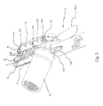
- the coupling element 20 is shown in more detail in Figures 2 and 3 , said figures respectively representing a view ( Fig. 2 ) wherein said coupling element 20 is associated with the structure 2, and a view ( Fig. 3 ) wherein it is associated with both the structure 2 and the actuator element 12.
- the coupling element 20 comprises a first end 21 having first connection means 21C to allow the coupling of said first end 21 to first fitting means 6 present on the structure 2 of the refrigeration appliance 1.
- Said first fitting means 6 are associated with an inner wall 7I of the structure 2.
- said first fitting means 6 are provided on at least one wing 8 associated with said inner wall 7I of said structure 2.
- Said first connection means comprise at least one first pin 21C, and said first fitting means comprise at least one first hole 6, said at least one first pin 21C being adapted to be inserted into said at least one first hole 6.
- first connection means 21C and first fitting means 6 may also be made otherwise; for example, in an alternative embodiment (not shown in the drawings), said first connection means 21C may be so designed as to comprise at least one first hole at the first end 21 of the coupling element 20, and said first fitting means 6 may be so designed as to comprise at least one first pin on said structure 2, in particular on an inner wall 7I of said structure 2, said at least one first hole being adapted to receive said at least one first pin.
- the coupling element 20 comprises a second end 22 having second connection means 22C to allow the coupling of said second end 22 to second fitting means 13 present on at least one junction portion 12G of the actuator element 12.
- said second connection means comprise at least one second pin 22C
- said second fitting means comprise at least one second hole 13, said at least one second pin 22C being adapted to be inserted into said at least one second hole 13.
- said second connection means 22C and said second fitting means 13 are possible as well; for example, in an alternative embodiment (not shown in the drawings) said second connection means 22C comprise at least one second hole and said second fitting means 13 comprise at least one second pin, said at least one second hole being adapted to receive said at least one second pin.
- said coupling element 20 has substantially the shape of a ladder, in particular (as can be seen especially in Fig. 2 ) said coupling element 20 comprising a pair of longitudinal ribs 20A joined together by at least one cross member 20B.
- each one of said ribs 20A comprises a first end 21 equipped with first connection means 21C and a second end 22 equipped with second connection means 22C.
- the actuator element 12 comprises at least one connecting portion 12P, in particular said connecting portion 12P being preferably formed with a substantially C-shaped profile adapted to receive the second end 22 of the rib 20A.
- the actuator element 12 comprises a pair of connecting portions 12P, each connecting portion 12P being preferably formed with a substantially C-shaped profile adapted to receive a second end 22 of the rib 20A.
- said particular "ladder-like" shape allows to facilitate the coupling of the coupling element 20 to the structure 2 of the refrigeration appliance 1 and to the actuator element 12, while also making the structure of said coupling element 20 lighter.
- the actuator element 12 also comprises a first portion 12A adapted to receive a thrust for obtaining the actuation of the valve 11; preferably, said first portion 12A of the actuator element 12 has a curved shape to ensure optimal coupling to the outer shape of a container C, e.g. a glass.
- a container C e.g. a glass.
- the actuator element 12 comprises a second portion 12B adapted to abut against a wall 11P of the valve 11, so as to actuate said valve 11 in response to a thrust exerted on the first portion 12A; furthermore, said second portion 12B is preferably formed to encircle at least one portion of said valve 11, in particular a terminal part of said valve 11.
- Fig. 4 is a perspective view of the refrigeration appliance 1.
- the refrigeration appliance 1 comprises a recess (designated as a whole by reference numeral 30) into which the valve 11 comes out for dispensing the beverage; said recess 30 is formed on an outer wall 7E of the structure 2, in particular an outer wall 7E of said at least one door 3P, 4P.
- first fitting means 6 and/ or said at least one wing 8 are associated with the inner wall 7I above said recess 30.
- the provision of the coupling element 20 according to the present invention allows both to facilitate the mounting of the actuator element 12 to said inner wall 7I above said recess 30 and to obtain an actuator element 12 having a longer lever arm.
- the lever arm is longer, in fact, there is no corresponding increase in the length of the arm of the actuator element 12; as a consequence, the second fitting means 13 of the actuator element 12 are not moved farther away from the aperture in the recess 30, thus not hindering the installation of said actuator element 12.
- the increased lever arm of the actuator element 12 allows the valve 11 to be operated by means of a smaller rotation of the actuator element 12 about said first fitting means 6 and first connection means 21C and, as a result, to obtain a shorter stroke of the end of the actuator element 12 in the recess 30.
- the coupling element 20 also acts as a guide for properly positioning the actuator element 12, since a user or an operator only has to:
- the junction portion 12G of the actuator element 12 substantially covers at least one half of the body of the coupling element 20. This ensures a strong coupling, with no flexure in the junction area between the actuator element 12 and the coupling element 20; at the same time, in order to prevent any problems of insertion between said actuator element 12 and coupling element 20, which might arise when the overlapping guided section becomes excessively long, the junction portion 12G preferably covers more than two thirds of the body of the coupling element 20.
- the coupling element 20 comprises a plurality of cross members 20B, and said junction portion 12G of the actuator element 12 is so designed as to substantially arrive at a lower cross member 20B when the actuator element 12 is associated with the coupling element (it must be pointed out that, in this context, the term "lower cross member 20B"refers to the position taken by the cross member 20B in an operating condition of the coupling element 20, i.e. in a situation in which the coupling element 20 is secured to the structure 2 of the refrigeration appliance 1).
- each cross member 20B confers adequate strength on the coupling element 20, while those sections of the coupling element 20 which do not include a cross member 20B advantageously give flexibility to the coupling element 20, thus allowing the ribs 20A to flex, in particular when the junction portion 12G of the actuator element 12 must slide over the coupling element 20, in particular by pressing down the protruding pins 22C.
- the cross members 20B are present on at least one half of the length of the coupling element 20, so as to give the latter adequate strength.
- the special provision of the coupling element 20 according to the present invention allows to provide a refrigeration appliance 1, in particular for household use, which allows to simplify the steps of coupling the actuator element 12 both to the structure 2 of the refrigeration appliance 1 and to the beverage dispensing valve 11.
- the provision of the coupling element 20 ensures high precision and accuracy during said coupling steps.
- Another advantage of the present invention is that the coupling element 20 according to the present invention allows to reduce any discomfort and waste of resources when mounting and securing the actuator element 12, while also significantly lowering the costs incurred for manufacturing the whole refrigeration appliance 1.
- a further advantage of the present invention is that, thanks to the coupling element 20 according to the present invention, it is not necessary to use a special tool for mounting the actuator element 12 outside the structure 2 or the door 3P, 4P of the refrigeration appliance 1 and for properly coupling it to the valve 11.
- the particular "ladder-like" shape of the coupling element 20 makes it easier to couple it to the structure 2 of the refrigeration appliance 1 and to the actuator element 12, while also making the structure of said coupling element 20 lighter.
Landscapes
- Engineering & Computer Science (AREA)
- Chemical & Material Sciences (AREA)
- Combustion & Propulsion (AREA)
- Physics & Mathematics (AREA)
- Mechanical Engineering (AREA)
- Thermal Sciences (AREA)
- General Engineering & Computer Science (AREA)
- Devices That Are Associated With Refrigeration Equipment (AREA)
- Apparatus For Making Beverages (AREA)
Abstract
- a valve (11) for dispensing said beverage, said valve (11) being located in such a position as to extend through a portion of the structure (2) of the refrigeration appliance (1) and to dispense said beverage outside said structure (2);
- an actuator element located outside the refrigeration appliance (1), said actuator element (12) being connected to the structure (2) of the refrigeration appliance (1) and being associated with said valve (11) to actuate it in order to dispense the beverage.
Description
- The present invention relates to a refrigeration appliance, in particular for household use, comprising a beverage dispensing device according to the preamble of
claim 1. - The present invention also relates to an associated beverage dispensing device.
- Reference will be prevalently made in the following description to a refrigeration appliance for household use, even though the present invention is not strictly limited to such an appliance.
- It is known in the art a refrigeration appliance, in particular for household use, of the type comprising a structure with at least one compartment formed therein for food preservation.
- Refrigeration appliances known in the art typically comprise two compartments which are kept at different temperatures, thus providing at least two different food preservation states, in particular a refrigerator compartment suitable for preserving fresh food at a temperature between 0°C and 10°C and a freezer compartment suitable for preserving frozen food at a temperature between -15°C and -30°C; such refrigeration appliances are commonly referred to by those skilled in the art of household refrigeration as "double-door" or "combined" refrigerators, depending on the relative position of the two compartments. In a "double-door" refrigeration appliance, the freezer compartment is arranged above the refrigerator compartment, whereas in a "combined" refrigeration appliance the freezer compartment is located at the bottom.
- It is also known in the art that a refrigeration appliance, in particular for household use, may include a device for dispensing a beverage outside said refrigeration appliance.
- Refrigeration appliances with such features have been common for decades in the USA; actually, the refrigeration appliances widespread on the American market are equipped with beverage dispensing devices capable of dispensing not only refrigerated water, but also ice and, in some cases, refrigerated soft drinks.
- In Europe, refrigeration appliances equipped with a beverage dispensing device have begun to catch on in quite recent times. It must be pointed out that the European market demands rather different products from those sold in the United States, i.e. products being much less bulky (60 or 70 cm wide) and usually dispensing refrigerated water only; moreover, such products must not be too expensive and therefore must use simple but effective technical solutions.
- Typically, said beverage dispensing device comprises:
- a beverage dispensing valve, said valve being so positioned as to extend through a portion of the structure of the refrigeration appliance, in particular of the door of said refrigeration appliance, and to dispense the beverage outside the structure;
- an actuator element located outside the refrigeration appliance, said actuator element being pivoted to the structure of the refrigeration appliance and being associated with said valve to actuate it in order to dispense the beverage.
- As a consequence, the valve is so positioned as to protrude both inside and outside the refrigeration appliance, and said actuator element is operated from the outside of the refrigeration appliance by a user wanting the beverage to exit the valve.
- Usually said valve is associated (whether directly or indirectly, e.g. by means of suitable ducts) with a reservoir located inside a compartment of the refrigeration appliance, in particular said reservoir being typically positioned in a refrigerator compartment; it is however clear that the valve may also be associated (in this case as well, either directly or indirectly, e.g. by means of suitable ducts or pipes) with the water main.
- Furthermore, on the external portion of the refrigeration appliance a recess is usually present where the beverage dispensing valve or the ducts associated therewith come out; in said recess, the user can insert and/or lay a container suitable for receiving the dispensed beverage, e.g. a glass.
- It has however been noticed that the refrigeration appliances currently known in the art suffer from a few drawbacks, which are essentially due to the particular position and construction of the beverage dispensing device, particularly of the beverage dispensing valve and of the associated actuator element.
- In particular, the refrigeration appliances known in the art are designed in a manner such that securing the actuator element associated with the valve into the structure, in particular into the door structure, is an extremely difficult task.
- In fact, said actuator element must be hinged to the structure or to the door of the refrigeration appliance in the proximity of the valve, so that the latter can be operated in order to dispense the beverage; it is apparent that, for the valve to be operated correctly, these operations must be carried out with great precision and accuracy.
- Moreover, such operations are made even more difficult by the fact that they are normally carried out when all other elements of the refrigeration appliance have already been assembled and installed; in such a condition, the operator is compelled to work from the outside of the structure or door, with only minimal room and visibility.
- It should be noted that the difficulties encountered when mounting and securing the actuator element increase with the length of the arm of the actuator element.
- It is clear that such difficulties inevitably imply much discomfort and waste of resources when assembling the refrigeration appliance, which of course adversely affect the costs incurred for manufacturing said refrigeration appliance.
- In addition, in the refrigeration appliances known in the art it is often the case that the actuator element can only be mounted to the structure or door of the refrigeration appliance and can only be properly positioned in the proximity of the valve by using a special tool; it is apparent that this contributes to increasing the difficulties and costs incurred for manufacturing prior-art refrigeration appliances.
- In this frame, it is the main object of the present invention to provide a refrigeration appliance, in particular for household use, which comprises a beverage dispensing device, and an associated beverage dispensing device, which are adapted to overcome the above-described drawbacks , thus proving particularly efficient and economical.
- In particular, it is one object of the present invention to provide a refrigeration appliance, in particular for household use, which is so designed that the steps required for securing the actuator element to the structure or to the door can be carried out in a simpler manner, while at the same time ensuring high precision and accuracy.
- It is another object of the present invention to provide a refrigeration appliance, in particular for household use, which is so designed as to reduce any discomfort and waste of resources when mounting and securing the actuator element for the beverage dispensing function, while also significantly lowering the costs incurred for manufacturing the whole refrigeration appliance.
- It is a further object of the present invention to provide a refrigeration appliance, in particular for household use, which is so designed as to not necessarily require the use of a special tool for mounting the actuator element outside the structure or door of the refrigeration appliance, or for properly coupling it to the beverage dispensing valve.
- To achieve said objects, the present invention provides a refrigeration appliance, in particular for household use, which comprises a beverage dispensing device, and an associated beverage dispensing device, which incorporate the features set out in the appended claims, which are intended to be an integral part of the present description.
- Further objects, features and advantages of the present invention will become apparent from the following detailed description and from the annexed drawings, which are supplied by way of non-limiting example, wherein:
-
Fig. 1 is a sectional side view of a refrigeration appliance according to the present invention; -
Figs. 2 and3 are perspective views of a component of the refrigeration appliance according to the present invention; -
Fig. 4 is a perspective view of a portion of the refrigeration appliance according to the present invention. - Said description and said drawings are to be considered as non-limiting examples.
- Referring now to the annexed drawings,
Fig. 1 shows a schematic sectional view of a refrigeration appliance, in particular for household use, in accordance with the present invention, designated as a whole byreference numeral 1. - Said
refrigeration appliance 1 comprises astructure 2 with at least onecompartment structure 2 comprising at least onedoor compartment - It must be pointed out that, for the purposes of the present invention, the
structure 2 generally referred to herein is meant to also include at least onedoor door structure 2. - Preferably, said at least one
compartment - a
refrigerator compartment 3, in particular suitable for preserving fresh food at a temperature between 0°C and 10°C, and adapted to be closed by afirst door 3P, - a
freezer compartment 4, in particular suitable for preserving frozen food at a temperature between -15°C and -30°C, and adapted to be closed by asecond door 4P. - It should be noted that the
refrigeration appliance 1 shown inFig. 1 is a "combined" one, in that thefreezer compartment 4 is located under therefrigerator compartment 3; it is however clear that therefrigeration appliance 1 according to the present invention may be of a different type as well. - Also,
Fig. 1 shows rather thick walls of thestructure 2, to indicate the presence of a layer of thermally insulating material; normally, the thickness of the insulating material depends on the type of cell (i.e. on the cell's operating temperatures) and, of course, on the type of insulating material in use; this is common and well known to those skilled in the art. - The
refrigeration appliance 1 comprises a beverage dispensing device, designated as a whole byreference numeral 10, saiddevice 10 comprising: - a
valve 11 for dispensing said beverage, saidvalve 11 being located in such a position as to extend through a portion of thestructure 2 of therefrigeration appliance 1 and to dispense said beverage outside saidstructure 2; - an
actuator element 12 located outside therefrigeration appliance 1, saidactuator element 12 being connected to thestructure 2 of therefrigeration appliance 1 and being associated with saidvalve 11 to actuate it in order to dispense the beverage. - Preferably, said
valve 11 is positioned in such a way as to extend through said at least onedoor refrigeration appliance 1; it is however clear that thevalve 11 may also be positioned in such a way as to cross thestructure 2 at different points, other than said at least onedoor - Furthermore, in the example of embodiment shown in
Fig. 1 thevalve 11 according to the present invention preferably also acts as a duct for dispensing the beverage outside therefrigeration appliance 1, in particular by transporting the beverage to arecess 30 formed in thestructure 2 of therefrigeration appliance 1, in particular on said at least onedoor valve 11 may be associated with other parts of thestructure 2, or with a suitable duct (not shown in the drawings) for conducting the beverage outside therefrigeration appliance 1 and into saidrecess 30. - The
valve 11 according to the present invention (and according to the example of embodiment shown inFig. 1 ) is preferably associated with areservoir 5 arranged inside therefrigeration appliance 1, in particular within therefrigerator compartment 3; it is however clear that thevalve 11 may also be associated, whether directly or indirectly, to a drinking water distribution main (not shown in the drawings). - Preferably, said
actuator element 12 is of the type that can be operated via a thrust exerted by a user wanting the beverage to exit the valve 11 (e.g. said thrust being exerted by means of a container, designated by reference C inFig. 1 ). - In accordance with the present invention, the
refrigeration appliance 1 comprises acoupling element 20 for connecting theactuator element 12 to thestructure 2 of therefrigeration appliance 1. - The special provision of the
coupling element 20 according to the present invention allows to provide arefrigeration appliance 1, in particular for household use, which allows to simplify the steps of coupling theactuator element 12 to thestructure 2 of therefrigeration appliance 1, so that said coupling steps can be carried out with the utmost precision and accuracy. - It is therefore apparent that the
coupling element 20 according to the present invention allows to provide arefrigeration appliance 1, in particular for household use, which is so designed as to reduce any discomfort and waste of resources when mounting and securing theactuator element 12, while also significantly lowering the costs incurred for manufacturing thewhole refrigeration appliance 1. - In addition, the
coupling element 20 according to the present invention does not necessarily require the use of a special tool for mounting theactuator element 12 outside the structure 2 (e.g. to adoor refrigeration appliance 1, or for properly coupling it to thevalve 11. - The
coupling element 20 is shown in more detail inFigures 2 and3 , said figures respectively representing a view (Fig. 2 ) wherein saidcoupling element 20 is associated with thestructure 2, and a view (Fig. 3 ) wherein it is associated with both thestructure 2 and theactuator element 12. - As can be observed in said figures, the
coupling element 20 comprises afirst end 21 having first connection means 21C to allow the coupling of saidfirst end 21 to first fitting means 6 present on thestructure 2 of therefrigeration appliance 1. - Said first fitting means 6 are associated with an inner wall 7I of the
structure 2. - In a preferred embodiment, said first fitting means 6 are provided on at least one
wing 8 associated with said inner wall 7I of saidstructure 2. - Said first connection means comprise at least one
first pin 21C, and said first fitting means comprise at least onefirst hole 6, said at least onefirst pin 21C being adapted to be inserted into said at least onefirst hole 6. - It is clear that said first connection means 21C and first fitting means 6 may also be made otherwise; for example, in an alternative embodiment (not shown in the drawings), said first connection means 21C may be so designed as to comprise at least one first hole at the
first end 21 of thecoupling element 20, and saidfirst fitting means 6 may be so designed as to comprise at least one first pin on saidstructure 2, in particular on an inner wall 7I of saidstructure 2, said at least one first hole being adapted to receive said at least one first pin. - In addition, the
coupling element 20 comprises asecond end 22 having second connection means 22C to allow the coupling of saidsecond end 22 to second fitting means 13 present on at least onejunction portion 12G of theactuator element 12. - In particular, said second connection means comprise at least one
second pin 22C, and said second fitting means comprise at least onesecond hole 13, said at least onesecond pin 22C being adapted to be inserted into said at least onesecond hole 13. - Also as concerns said second connection means 22C and said second fitting means 13, it is clear that different embodiments other than those shown in the annexed drawings are possible as well; for example, in an alternative embodiment (not shown in the drawings) said second connection means 22C comprise at least one second hole and said
second fitting means 13 comprise at least one second pin, said at least one second hole being adapted to receive said at least one second pin. - In a preferred embodiment, said
coupling element 20 has substantially the shape of a ladder, in particular (as can be seen especially inFig. 2 ) saidcoupling element 20 comprising a pair oflongitudinal ribs 20A joined together by at least onecross member 20B. - In this embodiment, each one of said
ribs 20A comprises afirst end 21 equipped with first connection means 21C and asecond end 22 equipped with second connection means 22C. - Preferably, the
actuator element 12 comprises at least one connecting portion 12P, in particular said connecting portion 12P being preferably formed with a substantially C-shaped profile adapted to receive thesecond end 22 of therib 20A. - With particular reference to the case wherein the
coupling element 20 has substantially the shape of a ladder, theactuator element 12 comprises a pair of connecting portions 12P, each connecting portion 12P being preferably formed with a substantially C-shaped profile adapted to receive asecond end 22 of therib 20A. - It is also clear that, especially in the case wherein the
coupling element 20 is substantially "ladder-shaped": - the first fitting means 6 are formed on a pair of
wings 8 associated with said inner wall 7I, in particular eachwing 8 comprising afirst hole 6 adapted to receive afirst pin 21C of thefirst end 21 of eachrib 20A; - the second fitting means 13 are formed on said pair of
junction portions 12G of theactuator element 12, in particular eachjunction portion 12G comprising asecond hole 13 adapted to receive asecond pin 22C of thesecond end 22 of eachrib 20A. - As a result, said particular "ladder-like" shape allows to facilitate the coupling of the
coupling element 20 to thestructure 2 of therefrigeration appliance 1 and to theactuator element 12, while also making the structure of saidcoupling element 20 lighter. - Preferably, the
actuator element 12 also comprises afirst portion 12A adapted to receive a thrust for obtaining the actuation of thevalve 11; preferably, saidfirst portion 12A of theactuator element 12 has a curved shape to ensure optimal coupling to the outer shape of a container C, e.g. a glass. - As can be seen especially in
Fig. 3 , theactuator element 12 comprises asecond portion 12B adapted to abut against awall 11P of thevalve 11, so as to actuate saidvalve 11 in response to a thrust exerted on thefirst portion 12A; furthermore, saidsecond portion 12B is preferably formed to encircle at least one portion of saidvalve 11, in particular a terminal part of saidvalve 11. -
Fig. 4 is a perspective view of therefrigeration appliance 1. - As can be seen in
Figures 1 and4 , therefrigeration appliance 1 according to the present invention comprises a recess (designated as a whole by reference numeral 30) into which thevalve 11 comes out for dispensing the beverage; saidrecess 30 is formed on anouter wall 7E of thestructure 2, in particular anouter wall 7E of said at least onedoor - In this drawing one can also see that the first fitting means 6 and/ or said at least one
wing 8 are associated with the inner wall 7I above saidrecess 30. - As a result, as can be seen especially in
Figures 3 and4 , one can understand that the provision of thecoupling element 20 according to the present invention allows both to facilitate the mounting of theactuator element 12 to said inner wall 7I above saidrecess 30 and to obtain anactuator element 12 having a longer lever arm. Although the lever arm is longer, in fact, there is no corresponding increase in the length of the arm of theactuator element 12; as a consequence, the second fitting means 13 of theactuator element 12 are not moved farther away from the aperture in therecess 30, thus not hindering the installation of saidactuator element 12. - The increased lever arm of the
actuator element 12 allows thevalve 11 to be operated by means of a smaller rotation of theactuator element 12 about said first fitting means 6 and first connection means 21C and, as a result, to obtain a shorter stroke of the end of theactuator element 12 in therecess 30. - It is apparent that such a provision turns out to be particularly advantageous in cases wherein the depth of the
recess 30 is small, i.e. whenever the depth of therecess 30 is not such as to allow for ample movements of theactuator element 12 about a pivot constituted by the first fitting means 6 and the first connection means 21C. - Furthermore, the
coupling element 20 according to the present invention also acts as a guide for properly positioning theactuator element 12, since a user or an operator only has to: - engage the
junction portion 12G of theactuator element 12 with thecoupling element 20; - push the
actuator element 12 upwards until theactuator element 12 is secured to the coupling element 20 (which is preferably achieved by coupling the second connection means 22C of thejunction portion 12G of thecoupling element 20 to the second fitting means 13 of the actuator element 12). - In a preferred embodiment, the
junction portion 12G of theactuator element 12 substantially covers at least one half of the body of thecoupling element 20. This ensures a strong coupling, with no flexure in the junction area between theactuator element 12 and thecoupling element 20; at the same time, in order to prevent any problems of insertion between saidactuator element 12 andcoupling element 20, which might arise when the overlapping guided section becomes excessively long, thejunction portion 12G preferably covers more than two thirds of the body of thecoupling element 20. - In a further preferred embodiment, the
coupling element 20 comprises a plurality ofcross members 20B, and saidjunction portion 12G of theactuator element 12 is so designed as to substantially arrive at alower cross member 20B when theactuator element 12 is associated with the coupling element (it must be pointed out that, in this context, the term "lower cross member 20B"refers to the position taken by thecross member 20B in an operating condition of thecoupling element 20, i.e. in a situation in which thecoupling element 20 is secured to thestructure 2 of the refrigeration appliance 1). - This shape of the
coupling element 20 proves to be particularly effective, in that eachcross member 20B confers adequate strength on thecoupling element 20, while those sections of thecoupling element 20 which do not include across member 20B advantageously give flexibility to thecoupling element 20, thus allowing theribs 20A to flex, in particular when thejunction portion 12G of theactuator element 12 must slide over thecoupling element 20, in particular by pressing down the protruding pins 22C. Advantageously, thecross members 20B are present on at least one half of the length of thecoupling element 20, so as to give the latter adequate strength. - The features and advantages of a refrigeration appliance, in particular for household use, and of an associated beverage dispensing device according to the present invention are apparent from the above description.
- In fact, the special provision of the
coupling element 20 according to the present invention allows to provide arefrigeration appliance 1, in particular for household use, which allows to simplify the steps of coupling theactuator element 12 both to thestructure 2 of therefrigeration appliance 1 and to thebeverage dispensing valve 11. - In addition, the provision of the
coupling element 20 ensures high precision and accuracy during said coupling steps. - Another advantage of the present invention is that the
coupling element 20 according to the present invention allows to reduce any discomfort and waste of resources when mounting and securing theactuator element 12, while also significantly lowering the costs incurred for manufacturing thewhole refrigeration appliance 1. - A further advantage of the present invention is that, thanks to the
coupling element 20 according to the present invention, it is not necessary to use a special tool for mounting theactuator element 12 outside thestructure 2 or thedoor refrigeration appliance 1 and for properly coupling it to thevalve 11. - Furthermore, the particular "ladder-like" shape of the
coupling element 20 makes it easier to couple it to thestructure 2 of therefrigeration appliance 1 and to theactuator element 12, while also making the structure of saidcoupling element 20 lighter. - It is however clear that many changes may be made to the refrigeration appliance, in particular for household use, and to the associated beverage dispensing device according to the present invention, and that in its practical implementation the various components may have different shapes and arrangements or be replaced with other technically equivalent elements without departing from the novelty spirit of the inventive idea.
- It can therefore be easily understood that the present invention is not limited to the above-described refrigeration appliance, in particular for household use, and to the associated beverage dispensing device, but may be subject to many modifications, improvements or replacements of equivalent parts and elements without departing from the inventive idea, as clearly specified in the following claims.
Claims (15)
- A refrigeration appliance (1), in particular for household use, comprising a structure (2) with at least one compartment (3, 4) formed therein for food preservation, and a beverage dispensing device (10), said device (10) comprising:- a valve (11) for dispensing said beverage, said valve (11) being located in such a position as to extend through a portion of the structure (2) of the refrigeration appliance (1) and to dispense said beverage outside said structure (2);- an actuator element (12) located outside the refrigeration appliance (1), said actuator element (12) being connected to the structure (2) of the refrigeration appliance (1) and being associated with said valve (11) to actuate it in order to dispense the beverage,
said refrigeration appliance (1) being characterized in that it comprises a coupling element (20) for connecting the actuator element (12) to the structure (2) of the refrigeration appliance (1). - A refrigeration appliance (1) as claimed in claim 1, characterized in that said coupling element (20) comprises:- a first end (21) having first connection means (21C) to allow the coupling of said first end (21) to first fitting means (6) present on the structure (2) of the refrigeration appliance (1);- a second end (22) having second connection means (22C) to allow the coupling of said second end (22) to second fitting means (13) present on at least one junction portion (12G) of the actuator element (12).
- A refrigeration appliance (1) as claimed in claim 2, characterized in that said first connection means comprise at least one first pin (21C) and said first fitting means comprise at least one first hole (6), said at least one first pin (21C) being adapted to fit into said at least one first hole (6).
- A refrigeration appliance (1) as claimed in claim 2, characterized in that said second connection means comprise at least one second pin (22C) and said second fitting means comprise at least one second hole (13), said at least one second pin (22C) being adapted to fit into said at least one second hole (13).
- A refrigeration appliance (1) as claimed in one or more of claims 2 to 4, characterized in that said first fitting means (6) are associated with an inner wall (7I) of the structure (2), in particular said first fitting means (6) being formed on at least one wing (8) associated with said inner wall (7I).
- A refrigeration appliance (1) as claimed in one or more of the preceding claims, characterized in that said coupling element (20) has substantially the shape of a ladder, said coupling element (20) comprising a pair of longitudinal ribs (20A) joined together by at least one cross member (20B).
- A refrigeration appliance (1) as claimed in claim 6, characterized in that each one of said ribs (20A) comprises a first end (21) equipped with first connection means (21C) and a second end (22) equipped with second connection means (22C).
- A refrigeration appliance (1) as claimed in one or more of the preceding claims, characterized in that said actuator element (12) comprises at least one connecting portion (12P), in particular formed with a substantially C-shaped profile, for receiving a second end (22) of the rib (20A).
- A refrigeration appliance (1) as claimed in one or more of the preceding claims, characterized in that said actuator element (12) comprises a first portion (12A) adapted to receive a thrust for obtaining the actuation of the valve (11), in particular said first portion (12A) having a curved shape for optimal coupling to the outer shape of a container (C).
- A refrigeration appliance (1) as claimed in claim 9, characterized in that said actuator element (12) comprises a second portion (12B) adapted to abut against a wall (11P) of the valve (11), so as to actuate said valve (11) in response to a thrust exerted on the first portion (12A).
- A refrigeration appliance (1) as claimed in claim 10, characterized in that said second portion (12B) is formed to encircle at least one portion of said valve (11), in particular a terminal part of said valve (11).
- A refrigeration appliance (1) as claimed in one or more of the preceding claims, characterized in that it comprises a recess (30) into which the valve (11) comes out for dispensing the beverage.
- A refrigeration appliance (1) as claimed in claim 12, characterized in that said recess (30) is formed on an outer wall (7E) of the structure (2), in particular an outer wall (7E) of said at least one door (3P, 4P).
- A refrigeration appliance (1) as claimed in one or more of the preceding claims, characterized in that said valve (11) is located in such a position as to extend through at least one door (3P, 4P) of the refrigeration appliance (1), in particular said valve (11) being associated with a reservoir (5) located within the refrigeration appliance (1), in particular within a refrigerator compartment (3).
- A coupling element (20) of a beverage dispensing device (10) as claimed in one or more of the preceding claims 1 to 14.
Applications Claiming Priority (1)
| Application Number | Priority Date | Filing Date | Title |
|---|---|---|---|
| IT000248A ITTO20120248A1 (en) | 2012-03-19 | 2012-03-19 | REFRIGERATION APPLIANCE, PARTICULARLY FOR HOUSEHOLD USE, INCLUDING A DEVICE FOR DELIVERING A DRINK |
Publications (3)
| Publication Number | Publication Date |
|---|---|
| EP2642226A2 true EP2642226A2 (en) | 2013-09-25 |
| EP2642226A3 EP2642226A3 (en) | 2013-11-20 |
| EP2642226B1 EP2642226B1 (en) | 2020-09-30 |
Family
ID=46548724
Family Applications (1)
| Application Number | Title | Priority Date | Filing Date |
|---|---|---|---|
| EP13158667.9A Active EP2642226B1 (en) | 2012-03-19 | 2013-03-11 | Refrigeration appliance, in particular for household use, comprising a beverage dispensing device |
Country Status (2)
| Country | Link |
|---|---|
| EP (1) | EP2642226B1 (en) |
| IT (1) | ITTO20120248A1 (en) |
Family Cites Families (6)
| Publication number | Priority date | Publication date | Assignee | Title |
|---|---|---|---|---|
| US4102660A (en) * | 1976-08-26 | 1978-07-25 | Whirlpool Corporation | Ice guide for refrigerator with external ice service |
| KR19990060081A (en) * | 1997-12-31 | 1999-07-26 | 윤종용 | Dispenser Damper in Refrigerator |
| KR100620370B1 (en) * | 1999-12-11 | 2006-09-06 | 삼성전자주식회사 | Refrigerator dispenser |
| TWI398399B (en) * | 2005-09-13 | 2013-06-11 | Lesaffre & Cie | Vanne de dosage comprenant un conduit interne fixe et un manchon externe mobile |
| KR100820818B1 (en) * | 2006-11-13 | 2008-04-11 | 엘지전자 주식회사 | Dispensing device and refrigerator using the same |
| US9581382B2 (en) * | 2009-06-22 | 2017-02-28 | Samsung Electronics Co., Ltd. | Lever for dispenser and refrigerator having the same |
-
2012
- 2012-03-19 IT IT000248A patent/ITTO20120248A1/en unknown
-
2013
- 2013-03-11 EP EP13158667.9A patent/EP2642226B1/en active Active
Non-Patent Citations (1)
| Title |
|---|
| None |
Also Published As
| Publication number | Publication date |
|---|---|
| EP2642226B1 (en) | 2020-09-30 |
| ITTO20120248A1 (en) | 2013-09-20 |
| EP2642226A3 (en) | 2013-11-20 |
Similar Documents
| Publication | Publication Date | Title |
|---|---|---|
| KR101401690B1 (en) | A mounting structure of a door-handle for refrigerator | |
| US11280541B2 (en) | Door end closure assembly with integrated user interface | |
| EP2846117B1 (en) | Refrigerator | |
| US7765645B2 (en) | Refrigerator | |
| EP3851777B1 (en) | Refrigerator | |
| US10502477B2 (en) | Refrigerator appliance | |
| US20090179539A1 (en) | Refrigerator door stop | |
| EP3690362B1 (en) | Refrigerator | |
| CN107110595A (en) | The door component of refrigerator and refrigerator | |
| EP2869007B1 (en) | Refrigerator | |
| CN102235790A (en) | Door handle and refrigerator having the same | |
| EP2933405A1 (en) | Door handle and refrigerator having the same | |
| CN102472562B (en) | Basket assembly for a refrigerator | |
| KR100825410B1 (en) | Handle structure for refrigerator | |
| EP3008409B1 (en) | Refrigerator | |
| EP2642226B1 (en) | Refrigeration appliance, in particular for household use, comprising a beverage dispensing device | |
| WO2003018945A1 (en) | A hinge | |
| EP2641864B1 (en) | Beverage dispensing valve, in particular for a household refrigeration appliance | |
| EP2645029B1 (en) | Refrigerating appliance, in particular for household use, comprising a device for distributing a beverage | |
| EP2641865A2 (en) | Beverage dispensing valve, in particular for a household refrigeration appliance | |
| EP2645027B1 (en) | Refrigeration appliance, in particular for household use, comprising a beverage dispensing device, and method of assembly thereof | |
| EP2917663B1 (en) | Domestic refrigeration device comprising a cooling air duct and a closure element integrated therein | |
| KR100612102B1 (en) | Ice outlet on the refrigerator | |
| KR102795654B1 (en) | Ice maker | |
| KR20090038729A (en) | Sliding door of refrigerator |
Legal Events
| Date | Code | Title | Description |
|---|---|---|---|
| PUAI | Public reference made under article 153(3) epc to a published international application that has entered the european phase |
Free format text: ORIGINAL CODE: 0009012 |
|
| AK | Designated contracting states |
Kind code of ref document: A2 Designated state(s): AL AT BE BG CH CY CZ DE DK EE ES FI FR GB GR HR HU IE IS IT LI LT LU LV MC MK MT NL NO PL PT RO RS SE SI SK SM TR |
|
| AX | Request for extension of the european patent |
Extension state: BA ME |
|
| PUAL | Search report despatched |
Free format text: ORIGINAL CODE: 0009013 |
|
| AK | Designated contracting states |
Kind code of ref document: A3 Designated state(s): AL AT BE BG CH CY CZ DE DK EE ES FI FR GB GR HR HU IE IS IT LI LT LU LV MC MK MT NL NO PL PT RO RS SE SI SK SM TR |
|
| AX | Request for extension of the european patent |
Extension state: BA ME |
|
| RIC1 | Information provided on ipc code assigned before grant |
Ipc: F25D 23/12 20060101AFI20131017BHEP |
|
| 17P | Request for examination filed |
Effective date: 20140506 |
|
| RBV | Designated contracting states (corrected) |
Designated state(s): AL AT BE BG CH CY CZ DE DK EE ES FI FR GB GR HR HU IE IS IT LI LT LU LV MC MK MT NL NO PL PT RO RS SE SI SK SM TR |
|
| RAP1 | Party data changed (applicant data changed or rights of an application transferred) |
Owner name: WHIRLPOOL EMEA S.P.A |
|
| STAA | Information on the status of an ep patent application or granted ep patent |
Free format text: STATUS: EXAMINATION IS IN PROGRESS |
|
| 17Q | First examination report despatched |
Effective date: 20180515 |
|
| GRAP | Despatch of communication of intention to grant a patent |
Free format text: ORIGINAL CODE: EPIDOSNIGR1 |
|
| STAA | Information on the status of an ep patent application or granted ep patent |
Free format text: STATUS: GRANT OF PATENT IS INTENDED |
|
| INTG | Intention to grant announced |
Effective date: 20200710 |
|
| GRAS | Grant fee paid |
Free format text: ORIGINAL CODE: EPIDOSNIGR3 |
|
| GRAA | (expected) grant |
Free format text: ORIGINAL CODE: 0009210 |
|
| STAA | Information on the status of an ep patent application or granted ep patent |
Free format text: STATUS: THE PATENT HAS BEEN GRANTED |
|
| AK | Designated contracting states |
Kind code of ref document: B1 Designated state(s): AL AT BE BG CH CY CZ DE DK EE ES FI FR GB GR HR HU IE IS IT LI LT LU LV MC MK MT NL NO PL PT RO RS SE SI SK SM TR |
|
| REG | Reference to a national code |
Ref country code: CH Ref legal event code: EP Ref country code: GB Ref legal event code: FG4D |
|
| REG | Reference to a national code |
Ref country code: AT Ref legal event code: REF Ref document number: 1319216 Country of ref document: AT Kind code of ref document: T Effective date: 20201015 |
|
| REG | Reference to a national code |
Ref country code: DE Ref legal event code: R096 Ref document number: 602013072868 Country of ref document: DE |
|
| REG | Reference to a national code |
Ref country code: IE Ref legal event code: FG4D |
|
| PG25 | Lapsed in a contracting state [announced via postgrant information from national office to epo] |
Ref country code: GR Free format text: LAPSE BECAUSE OF FAILURE TO SUBMIT A TRANSLATION OF THE DESCRIPTION OR TO PAY THE FEE WITHIN THE PRESCRIBED TIME-LIMIT Effective date: 20201231 Ref country code: BG Free format text: LAPSE BECAUSE OF FAILURE TO SUBMIT A TRANSLATION OF THE DESCRIPTION OR TO PAY THE FEE WITHIN THE PRESCRIBED TIME-LIMIT Effective date: 20201230 Ref country code: NO Free format text: LAPSE BECAUSE OF FAILURE TO SUBMIT A TRANSLATION OF THE DESCRIPTION OR TO PAY THE FEE WITHIN THE PRESCRIBED TIME-LIMIT Effective date: 20201230 Ref country code: FI Free format text: LAPSE BECAUSE OF FAILURE TO SUBMIT A TRANSLATION OF THE DESCRIPTION OR TO PAY THE FEE WITHIN THE PRESCRIBED TIME-LIMIT Effective date: 20200930 Ref country code: SE Free format text: LAPSE BECAUSE OF FAILURE TO SUBMIT A TRANSLATION OF THE DESCRIPTION OR TO PAY THE FEE WITHIN THE PRESCRIBED TIME-LIMIT Effective date: 20200930 Ref country code: HR Free format text: LAPSE BECAUSE OF FAILURE TO SUBMIT A TRANSLATION OF THE DESCRIPTION OR TO PAY THE FEE WITHIN THE PRESCRIBED TIME-LIMIT Effective date: 20200930 |
|
| REG | Reference to a national code |
Ref country code: AT Ref legal event code: MK05 Ref document number: 1319216 Country of ref document: AT Kind code of ref document: T Effective date: 20200930 |
|
| PG25 | Lapsed in a contracting state [announced via postgrant information from national office to epo] |
Ref country code: LV Free format text: LAPSE BECAUSE OF FAILURE TO SUBMIT A TRANSLATION OF THE DESCRIPTION OR TO PAY THE FEE WITHIN THE PRESCRIBED TIME-LIMIT Effective date: 20200930 Ref country code: RS Free format text: LAPSE BECAUSE OF FAILURE TO SUBMIT A TRANSLATION OF THE DESCRIPTION OR TO PAY THE FEE WITHIN THE PRESCRIBED TIME-LIMIT Effective date: 20200930 |
|
| REG | Reference to a national code |
Ref country code: NL Ref legal event code: MP Effective date: 20200930 |
|
| REG | Reference to a national code |
Ref country code: LT Ref legal event code: MG4D |
|
| PG25 | Lapsed in a contracting state [announced via postgrant information from national office to epo] |
Ref country code: LT Free format text: LAPSE BECAUSE OF FAILURE TO SUBMIT A TRANSLATION OF THE DESCRIPTION OR TO PAY THE FEE WITHIN THE PRESCRIBED TIME-LIMIT Effective date: 20200930 Ref country code: NL Free format text: LAPSE BECAUSE OF FAILURE TO SUBMIT A TRANSLATION OF THE DESCRIPTION OR TO PAY THE FEE WITHIN THE PRESCRIBED TIME-LIMIT Effective date: 20200930 Ref country code: PT Free format text: LAPSE BECAUSE OF FAILURE TO SUBMIT A TRANSLATION OF THE DESCRIPTION OR TO PAY THE FEE WITHIN THE PRESCRIBED TIME-LIMIT Effective date: 20210201 Ref country code: RO Free format text: LAPSE BECAUSE OF FAILURE TO SUBMIT A TRANSLATION OF THE DESCRIPTION OR TO PAY THE FEE WITHIN THE PRESCRIBED TIME-LIMIT Effective date: 20200930 Ref country code: SM Free format text: LAPSE BECAUSE OF FAILURE TO SUBMIT A TRANSLATION OF THE DESCRIPTION OR TO PAY THE FEE WITHIN THE PRESCRIBED TIME-LIMIT Effective date: 20200930 Ref country code: EE Free format text: LAPSE BECAUSE OF FAILURE TO SUBMIT A TRANSLATION OF THE DESCRIPTION OR TO PAY THE FEE WITHIN THE PRESCRIBED TIME-LIMIT Effective date: 20200930 Ref country code: CZ Free format text: LAPSE BECAUSE OF FAILURE TO SUBMIT A TRANSLATION OF THE DESCRIPTION OR TO PAY THE FEE WITHIN THE PRESCRIBED TIME-LIMIT Effective date: 20200930 |
|
| PG25 | Lapsed in a contracting state [announced via postgrant information from national office to epo] |
Ref country code: AL Free format text: LAPSE BECAUSE OF FAILURE TO SUBMIT A TRANSLATION OF THE DESCRIPTION OR TO PAY THE FEE WITHIN THE PRESCRIBED TIME-LIMIT Effective date: 20200930 Ref country code: AT Free format text: LAPSE BECAUSE OF FAILURE TO SUBMIT A TRANSLATION OF THE DESCRIPTION OR TO PAY THE FEE WITHIN THE PRESCRIBED TIME-LIMIT Effective date: 20200930 Ref country code: ES Free format text: LAPSE BECAUSE OF FAILURE TO SUBMIT A TRANSLATION OF THE DESCRIPTION OR TO PAY THE FEE WITHIN THE PRESCRIBED TIME-LIMIT Effective date: 20200930 Ref country code: PL Free format text: LAPSE BECAUSE OF FAILURE TO SUBMIT A TRANSLATION OF THE DESCRIPTION OR TO PAY THE FEE WITHIN THE PRESCRIBED TIME-LIMIT Effective date: 20200930 Ref country code: IS Free format text: LAPSE BECAUSE OF FAILURE TO SUBMIT A TRANSLATION OF THE DESCRIPTION OR TO PAY THE FEE WITHIN THE PRESCRIBED TIME-LIMIT Effective date: 20210130 |
|
| PG25 | Lapsed in a contracting state [announced via postgrant information from national office to epo] |
Ref country code: SK Free format text: LAPSE BECAUSE OF FAILURE TO SUBMIT A TRANSLATION OF THE DESCRIPTION OR TO PAY THE FEE WITHIN THE PRESCRIBED TIME-LIMIT Effective date: 20200930 |
|
| REG | Reference to a national code |
Ref country code: DE Ref legal event code: R097 Ref document number: 602013072868 Country of ref document: DE |
|
| PLBE | No opposition filed within time limit |
Free format text: ORIGINAL CODE: 0009261 |
|
| STAA | Information on the status of an ep patent application or granted ep patent |
Free format text: STATUS: NO OPPOSITION FILED WITHIN TIME LIMIT |
|
| PG25 | Lapsed in a contracting state [announced via postgrant information from national office to epo] |
Ref country code: DK Free format text: LAPSE BECAUSE OF FAILURE TO SUBMIT A TRANSLATION OF THE DESCRIPTION OR TO PAY THE FEE WITHIN THE PRESCRIBED TIME-LIMIT Effective date: 20200930 |
|
| 26N | No opposition filed |
Effective date: 20210701 |
|
| PG25 | Lapsed in a contracting state [announced via postgrant information from national office to epo] |
Ref country code: MC Free format text: LAPSE BECAUSE OF FAILURE TO SUBMIT A TRANSLATION OF THE DESCRIPTION OR TO PAY THE FEE WITHIN THE PRESCRIBED TIME-LIMIT Effective date: 20200930 |
|
| REG | Reference to a national code |
Ref country code: CH Ref legal event code: PL |
|
| PG25 | Lapsed in a contracting state [announced via postgrant information from national office to epo] |
Ref country code: SI Free format text: LAPSE BECAUSE OF FAILURE TO SUBMIT A TRANSLATION OF THE DESCRIPTION OR TO PAY THE FEE WITHIN THE PRESCRIBED TIME-LIMIT Effective date: 20200930 |
|
| REG | Reference to a national code |
Ref country code: BE Ref legal event code: MM Effective date: 20210331 |
|
| PG25 | Lapsed in a contracting state [announced via postgrant information from national office to epo] |
Ref country code: IE Free format text: LAPSE BECAUSE OF NON-PAYMENT OF DUE FEES Effective date: 20210311 Ref country code: CH Free format text: LAPSE BECAUSE OF NON-PAYMENT OF DUE FEES Effective date: 20210331 Ref country code: LU Free format text: LAPSE BECAUSE OF NON-PAYMENT OF DUE FEES Effective date: 20210311 Ref country code: LI Free format text: LAPSE BECAUSE OF NON-PAYMENT OF DUE FEES Effective date: 20210331 |
|
| PGFP | Annual fee paid to national office [announced via postgrant information from national office to epo] |
Ref country code: GB Payment date: 20220120 Year of fee payment: 10 |
|
| PG25 | Lapsed in a contracting state [announced via postgrant information from national office to epo] |
Ref country code: IS Free format text: LAPSE BECAUSE OF FAILURE TO SUBMIT A TRANSLATION OF THE DESCRIPTION OR TO PAY THE FEE WITHIN THE PRESCRIBED TIME-LIMIT Effective date: 20210130 |
|
| PGFP | Annual fee paid to national office [announced via postgrant information from national office to epo] |
Ref country code: IT Payment date: 20220210 Year of fee payment: 10 Ref country code: FR Payment date: 20220118 Year of fee payment: 10 |
|
| PG25 | Lapsed in a contracting state [announced via postgrant information from national office to epo] |
Ref country code: BE Free format text: LAPSE BECAUSE OF NON-PAYMENT OF DUE FEES Effective date: 20210331 |
|
| PG25 | Lapsed in a contracting state [announced via postgrant information from national office to epo] |
Ref country code: HU Free format text: LAPSE BECAUSE OF FAILURE TO SUBMIT A TRANSLATION OF THE DESCRIPTION OR TO PAY THE FEE WITHIN THE PRESCRIBED TIME-LIMIT; INVALID AB INITIO Effective date: 20130311 |
|
| P01 | Opt-out of the competence of the unified patent court (upc) registered |
Effective date: 20230523 |
|
| PG25 | Lapsed in a contracting state [announced via postgrant information from national office to epo] |
Ref country code: CY Free format text: LAPSE BECAUSE OF FAILURE TO SUBMIT A TRANSLATION OF THE DESCRIPTION OR TO PAY THE FEE WITHIN THE PRESCRIBED TIME-LIMIT Effective date: 20200930 |
|
| REG | Reference to a national code |
Ref country code: DE Ref legal event code: R081 Ref document number: 602013072868 Country of ref document: DE Owner name: WHIRLPOOL EMEA S.R.L., IT Free format text: FORMER OWNER: WHIRLPOOL EMEA S.P.A, PERO, IT |
|
| GBPC | Gb: european patent ceased through non-payment of renewal fee |
Effective date: 20230311 |
|
| PG25 | Lapsed in a contracting state [announced via postgrant information from national office to epo] |
Ref country code: GB Free format text: LAPSE BECAUSE OF NON-PAYMENT OF DUE FEES Effective date: 20230311 |
|
| PG25 | Lapsed in a contracting state [announced via postgrant information from national office to epo] |
Ref country code: GB Free format text: LAPSE BECAUSE OF NON-PAYMENT OF DUE FEES Effective date: 20230311 Ref country code: FR Free format text: LAPSE BECAUSE OF NON-PAYMENT OF DUE FEES Effective date: 20230331 |
|
| PG25 | Lapsed in a contracting state [announced via postgrant information from national office to epo] |
Ref country code: MK Free format text: LAPSE BECAUSE OF FAILURE TO SUBMIT A TRANSLATION OF THE DESCRIPTION OR TO PAY THE FEE WITHIN THE PRESCRIBED TIME-LIMIT Effective date: 20200930 Ref country code: IT Free format text: LAPSE BECAUSE OF NON-PAYMENT OF DUE FEES Effective date: 20230311 |
|
| PG25 | Lapsed in a contracting state [announced via postgrant information from national office to epo] |
Ref country code: MT Free format text: LAPSE BECAUSE OF FAILURE TO SUBMIT A TRANSLATION OF THE DESCRIPTION OR TO PAY THE FEE WITHIN THE PRESCRIBED TIME-LIMIT Effective date: 20200930 |
|
| PG25 | Lapsed in a contracting state [announced via postgrant information from national office to epo] |
Ref country code: TR Free format text: LAPSE BECAUSE OF FAILURE TO SUBMIT A TRANSLATION OF THE DESCRIPTION OR TO PAY THE FEE WITHIN THE PRESCRIBED TIME-LIMIT Effective date: 20200930 |
|
| PGFP | Annual fee paid to national office [announced via postgrant information from national office to epo] |
Ref country code: DE Payment date: 20260320 Year of fee payment: 14 |