EP2642199A1 - Circulating fluidized bed boiler - Google Patents
Circulating fluidized bed boiler Download PDFInfo
- Publication number
- EP2642199A1 EP2642199A1 EP12160406.0A EP12160406A EP2642199A1 EP 2642199 A1 EP2642199 A1 EP 2642199A1 EP 12160406 A EP12160406 A EP 12160406A EP 2642199 A1 EP2642199 A1 EP 2642199A1
- Authority
- EP
- European Patent Office
- Prior art keywords
- heat transfer
- boiler
- vertical
- chamber
- transfer surface
- Prior art date
- Legal status (The legal status is an assumption and is not a legal conclusion. Google has not performed a legal analysis and makes no representation as to the accuracy of the status listed.)
- Granted
Links
Images
Classifications
-
- F—MECHANICAL ENGINEERING; LIGHTING; HEATING; WEAPONS; BLASTING
- F23—COMBUSTION APPARATUS; COMBUSTION PROCESSES
- F23C—METHODS OR APPARATUS FOR COMBUSTION USING FLUID FUEL OR SOLID FUEL SUSPENDED IN A CARRIER GAS OR AIR
- F23C10/00—Fluidised bed combustion apparatus
- F23C10/02—Fluidised bed combustion apparatus with means specially adapted for achieving or promoting a circulating movement of particles within the bed or for a recirculation of particles entrained from the bed
- F23C10/04—Fluidised bed combustion apparatus with means specially adapted for achieving or promoting a circulating movement of particles within the bed or for a recirculation of particles entrained from the bed the particles being circulated to a section, e.g. a heat-exchange section or a return duct, at least partially shielded from the combustion zone, before being reintroduced into the combustion zone
- F23C10/08—Fluidised bed combustion apparatus with means specially adapted for achieving or promoting a circulating movement of particles within the bed or for a recirculation of particles entrained from the bed the particles being circulated to a section, e.g. a heat-exchange section or a return duct, at least partially shielded from the combustion zone, before being reintroduced into the combustion zone characterised by the arrangement of separation apparatus, e.g. cyclones, for separating particles from the flue gases
- F23C10/10—Fluidised bed combustion apparatus with means specially adapted for achieving or promoting a circulating movement of particles within the bed or for a recirculation of particles entrained from the bed the particles being circulated to a section, e.g. a heat-exchange section or a return duct, at least partially shielded from the combustion zone, before being reintroduced into the combustion zone characterised by the arrangement of separation apparatus, e.g. cyclones, for separating particles from the flue gases the separation apparatus being located outside the combustion chamber
-
- F—MECHANICAL ENGINEERING; LIGHTING; HEATING; WEAPONS; BLASTING
- F22—STEAM GENERATION
- F22B—METHODS OF STEAM GENERATION; STEAM BOILERS
- F22B21/00—Water-tube boilers of vertical or steeply-inclined type, i.e. the water-tube sets being arranged vertically or substantially vertically
- F22B21/22—Water-tube boilers of vertical or steeply-inclined type, i.e. the water-tube sets being arranged vertically or substantially vertically built-up from water tubes of form other than straight or substantially straight
- F22B21/30—Water-tube boilers of vertical or steeply-inclined type, i.e. the water-tube sets being arranged vertically or substantially vertically built-up from water tubes of form other than straight or substantially straight bent in U-loop form
-
- F—MECHANICAL ENGINEERING; LIGHTING; HEATING; WEAPONS; BLASTING
- F22—STEAM GENERATION
- F22B—METHODS OF STEAM GENERATION; STEAM BOILERS
- F22B21/00—Water-tube boilers of vertical or steeply-inclined type, i.e. the water-tube sets being arranged vertically or substantially vertically
- F22B21/40—Water-tube boilers of vertical or steeply-inclined type, i.e. the water-tube sets being arranged vertically or substantially vertically built-up from water tubes arranged in a comparatively long vertical shaft, i.e. tower boilers
-
- F—MECHANICAL ENGINEERING; LIGHTING; HEATING; WEAPONS; BLASTING
- F22—STEAM GENERATION
- F22B—METHODS OF STEAM GENERATION; STEAM BOILERS
- F22B31/00—Modifications of boiler construction, or of tube systems, dependent on installation of combustion apparatus; Arrangements or dispositions of combustion apparatus
- F22B31/0007—Modifications of boiler construction, or of tube systems, dependent on installation of combustion apparatus; Arrangements or dispositions of combustion apparatus with combustion in a fluidized bed
- F22B31/0015—Modifications of boiler construction, or of tube systems, dependent on installation of combustion apparatus; Arrangements or dispositions of combustion apparatus with combustion in a fluidized bed for boilers of the water tube type
-
- F—MECHANICAL ENGINEERING; LIGHTING; HEATING; WEAPONS; BLASTING
- F22—STEAM GENERATION
- F22B—METHODS OF STEAM GENERATION; STEAM BOILERS
- F22B37/00—Component parts or details of steam boilers
- F22B37/02—Component parts or details of steam boilers applicable to more than one kind or type of steam boiler
- F22B37/48—Devices or arrangements for removing water, minerals or sludge from boilers ; Arrangement of cleaning apparatus in boilers; Combinations thereof with boilers
- F22B37/50—Devices or arrangements for removing water, minerals or sludge from boilers ; Arrangement of cleaning apparatus in boilers; Combinations thereof with boilers for draining or expelling water
-
- F—MECHANICAL ENGINEERING; LIGHTING; HEATING; WEAPONS; BLASTING
- F23—COMBUSTION APPARATUS; COMBUSTION PROCESSES
- F23M—CASINGS, LININGS, WALLS OR DOORS SPECIALLY ADAPTED FOR COMBUSTION CHAMBERS, e.g. FIREBRIDGES; DEVICES FOR DEFLECTING AIR, FLAMES OR COMBUSTION PRODUCTS IN COMBUSTION CHAMBERS; SAFETY ARRANGEMENTS SPECIALLY ADAPTED FOR COMBUSTION APPARATUS; DETAILS OF COMBUSTION CHAMBERS, NOT OTHERWISE PROVIDED FOR
- F23M5/00—Casings; Linings; Walls
- F23M5/08—Cooling thereof; Tube walls
-
- F—MECHANICAL ENGINEERING; LIGHTING; HEATING; WEAPONS; BLASTING
- F23—COMBUSTION APPARATUS; COMBUSTION PROCESSES
- F23C—METHODS OR APPARATUS FOR COMBUSTION USING FLUID FUEL OR SOLID FUEL SUSPENDED IN A CARRIER GAS OR AIR
- F23C2206/00—Fluidised bed combustion
- F23C2206/10—Circulating fluidised bed
Definitions
- the present invention is related to a circulating fluidized bed (CFB) boiler, including a reactor where the solid particles are fluidized and where chemical reactions and/or combustion reactions can take place.
- the circulating fluidized regime enhances the mixing of particles along with potential exothermic or endothermic chemical reactions.
- the furnace of a conventional fluidized bed boiler is defined by four external side walls, a bottom and a roof and potentially inner walls to ensure the sealing with the outside if multiple fluidizing grates are used. All the walls constitute an ash-tight enclosure in which the solid particles including the fuel material are fluidized.
- Air is introduced into the furnace to fluidize the solid particles and also brings the needed oxygen for combustion.
- Two air streams can be used.
- Primary air is mostly used to fluidize the particles, flows through the fluidizing grate which constitutes the bottom of the furnace.
- Secondary air is the additional air required for a complete combustion and is introduced through several ports located over the external side walls and/or inner walls if the bottom part of the furnace comprises a dual fluidizing grate and whose shape can be described like a pant leg.
- the furnace enclosure is usually made of gastight panels formed with finned tubes.
- the heat released from the combustion of fuel is transferred to water or steam flowing inside the tubes and also allowing the tubes to be cooled.
- the overall surface of the furnace enclosure cannot match the total heat released from the combustion and additional surfaces have to be implemented either in the furnace and/or potentially in external devices of the furnace that are supplied with the solid particles escaping the furnace and collected by the cyclones before returning to the furnace.
- Increasing the height of the furnace may be also considered but this solution is not cost-effective and can result in mechanical problems or worst performances.
- Wing walls or U-shaped panels can be implemented for increasing the heating surface in the furnace.
- Wing walls are usually made of panels with totally or partly finned tubes and are laid out in a vertical area.
- a header is usually located at the top of the wing and a header is usually located at the bottom of the wing.
- the panels cross the vertical side wall of furnace with a gastight connection which prevents any displacement of panels over the crossing zone with the side wall.
- the panels also cross the roof where a vertical displacement due to the thermal expansion is allowed via the expansion joint.
- a U-shaped panel is made of two panels with or without finned tubes that are laid out in a vertical plan and are connected at one of their extremities by tubes for ensuring a continuous path for the fluid.
- the fluid inside the tubes flows down through the first panel and flows up through the second panel after being returned into the bottom of the U shape.
- a U-shaped panel is usually not drainable due to the location of the headers which are at the top of panel.
- the inlet and outlet headers can be located above the roof so that the tip of the U-shaped panel is free to displace in all the horizontal directions.
- a fluidizing regime can lead to vibrations of the U-shaped panel which leads to mechanical failures.
- the magnitude of the displacement is linked to the height of the U-panel so that the risk of failure due to vibration increases with the height of U-shaped panel.
- an object of the present invention is to provide a circulating fluidized bed boiler as to solve the above-described problems.
- a circulating fluidized bed boiler comprising a combustion chamber comprising:
- Every vertical chamber is preferably made of gastight panels formed with finned tubes and every second heat transfer surface can be made of tube panels.
- Each second heat transfer surface is preferably U-shaped.
- the combustion chamber being defined by side walls, a roof and a bottom
- the first heat transfer surfaces can extend from the bottom or from inclined walls joining the bottom and the second heat transfer surfaces can extend from the roof of the combustion chamber.
- the second heat transfer surfaces could alternatively extend from an upper part of the side walls.
- Every U-shaped second heat transfer surface can comprise two vertical parts that are fixed at its lower extremity to a chamber.
- Each U-shaped second heat transfer surface can extend downwards at least 40% of the height of the combustion chamber, and preferably between 40 and 70% of the height of the combustion chamber. This high extension rate is made possible thanks to the specific heat transfer structure according to the invention.
- Every second heat transfer surface can pass through the chamber.
- the part of the second heat transfer surface that is located inside the chamber preferably comprises at least one bended portion.
- the second heat transfer surface can be made of tube panels, the tubes entering and leaving the vertical chamber in a direction parallel to a vertical axis of symmetry of the second heat transfer surface (for instance the longitudinal axe in the case the horizontal cross-section of the vertical chamber is a rectangle), and the tubes can have a first bended portion on one side of the axis of symmetry followed by a second bended portion on the other side of the axis of symmetry.
- the horizontal cross-section of the vertical chamber can be a polygon (for instance a rectangle) or a circle.
- Each second heat transfer surface can comprise a bottle for draining the condensates during the start-up of the boiler.
- Figure 1 illustrates a fluidized bed reactor having an exemplary structure according to the present invention.
- the main parts of the boiler 1 are the furnace 2 and the particle separators 3.
- the furnace 2 is defined by side walls 4, a bottom 5 and a roof 6.
- the furnace 2 is provided with ports for feeding fuel and other bed material, e.g. sand and limestone.
- the bottom 5 of the furnace 2 is provided with means for supplying air for fluidizing the bed material.
- the lower portion of the furnace 2 is also provided with ducts for supplying secondary air.
- Ash and bed material are discharged together with the fluidizing air and flue gases through ducts to the separators 3, where most part of the solid material is separated from the flue gases and returned through a return pipe to the lower portion of the furnace 2.
- the side walls 4 of the furnace can be formed of tube panels consisting of finned tubes not shown in detail in the figure.
- the energy released from the combustion of fuel is used for vaporizing the water flowing in the tubes of the side walls 4.
- the walls of the chambers 7 are made of tube panels, the tubes of which are joined to feed pipes below the furnace and to header pipes above the furnace.
- Inside the chambers 7 there are preferably means for supplying secondary air and fuel to the center part of the furnace 2.
- the chambers 7 can be spaced away from the side walls 4 and arranged separately within the furnace 2, for the furnace volume to be free for the particles to move even in the proximity of said chambers 7.
- the chambers 7 can extend from the bottom 5 of the furnace 2, or, as illustrated in figure 1 , can extend from an inclined wall of a pant-leg configuration, i.e. a configuration in which inclined walls extend upwards the bottom 5.
- the pant-leg design is typical for higher capacity boilers because it allows for better secondary air penetration, maintaining good air-coal mixing as well as efficient combustion.
- the pant-leg structured CFB boiler features two separated legs with solid particles fluidized by independent primary air supplies.
- the possible shapes of the chambers 7 are illustrated in figure 3 .
- the cross-section of the chambers can be a rectangle, a circle or a polygon.
- the furnace 2 further includes U-shaped panels 8 made of tubes and which are heating or superheating surfaces.
- the panels 8 are supported by headers located above the roof 6.
- the bottoms of the panels 8 are fixed to the chambers 7. This fixation makes it possible to prevent horizontal displacements of the bottom part of the panels 8.
- every U-shaped panel 8 can be constituted of two L-shaped parts that are each fixed at a wall of a chamber 7.
- the free space inside the box can be used for implementing a bottle 10 to drain the condensates during the start-up of the boiler.
- a drain pipe 11 is fitted to the bottom of the bottle 10 to evacuate the condensates ( Figure 4 ).
- the tubes of the panel 8 can be bended inside the box to make up for the difference of thermal expansion between the chamber 7 and the panel 8.
- the tubes can enter and leave the chamber in a direction parallel to the longitudinal axe of the rectangle, the tubes having a first bended portion on one side of the longitudinal axe followed by a second bended portion on the other side of the longitudinal axe.
- the tubes can have an inlet portion that is parallel to the longitudinal axe of the rectangle, followed by a first bended portion deflecting from the longitudinal axe on one side (for instance on the left-hand side), followed by a second bended portion deflecting from the longitudinal axe on the other side (on the right-hand side), followed by an outlet portion that is parallel to the longitudinal axe of the rectangle.
- the inlet portion and the first bended portion can be located in one half length of the rectangle whereas the second bended portion and the outlet portion can be located in the other half length of the rectangle.
- every panel 8 is connected to a chamber 7 along with a dual grate design.
- panels 8 connected to chambers 7 alternate with panels 9 which are not connected to a chamber ( Figure 7 ).
Landscapes
- Engineering & Computer Science (AREA)
- Mechanical Engineering (AREA)
- General Engineering & Computer Science (AREA)
- Chemical & Material Sciences (AREA)
- Combustion & Propulsion (AREA)
- Physics & Mathematics (AREA)
- Thermal Sciences (AREA)
- Fluidized-Bed Combustion And Resonant Combustion (AREA)
Abstract
- first heat transfer surfaces (7) forming at least one vertical chamber extending from a lower part (5) of the combustion chamber (2), and
- second heat transfer surfaces (8) having an inlet part and an outlet part which extend both from an upper part (6) of the combustion chamber (2), said second heat transfer surfaces (8) being fixed to vertical chambers (7).
Description
- The present invention is related to a circulating fluidized bed (CFB) boiler, including a reactor where the solid particles are fluidized and where chemical reactions and/or combustion reactions can take place. The circulating fluidized regime enhances the mixing of particles along with potential exothermic or endothermic chemical reactions.
- The furnace of a conventional fluidized bed boiler is defined by four external side walls, a bottom and a roof and potentially inner walls to ensure the sealing with the outside if multiple fluidizing grates are used. All the walls constitute an ash-tight enclosure in which the solid particles including the fuel material are fluidized.
- Air is introduced into the furnace to fluidize the solid particles and also brings the needed oxygen for combustion. Two air streams can be used. Primary air is mostly used to fluidize the particles, flows through the fluidizing grate which constitutes the bottom of the furnace. Secondary air is the additional air required for a complete combustion and is introduced through several ports located over the external side walls and/or inner walls if the bottom part of the furnace comprises a dual fluidizing grate and whose shape can be described like a pant leg.
- The furnace enclosure is usually made of gastight panels formed with finned tubes. The heat released from the combustion of fuel is transferred to water or steam flowing inside the tubes and also allowing the tubes to be cooled. When increasing the capacity of the boiler, the overall surface of the furnace enclosure cannot match the total heat released from the combustion and additional surfaces have to be implemented either in the furnace and/or potentially in external devices of the furnace that are supplied with the solid particles escaping the furnace and collected by the cyclones before returning to the furnace. Increasing the height of the furnace may be also considered but this solution is not cost-effective and can result in mechanical problems or worst performances.
- Wing walls or U-shaped panels can be implemented for increasing the heating surface in the furnace. Wing walls are usually made of panels with totally or partly finned tubes and are laid out in a vertical area. A header is usually located at the top of the wing and a header is usually located at the bottom of the wing. The panels cross the vertical side wall of furnace with a gastight connection which prevents any displacement of panels over the crossing zone with the side wall. The panels also cross the roof where a vertical displacement due to the thermal expansion is allowed via the expansion joint.
- A U-shaped panel is made of two panels with or without finned tubes that are laid out in a vertical plan and are connected at one of their extremities by tubes for ensuring a continuous path for the fluid. The fluid inside the tubes flows down through the first panel and flows up through the second panel after being returned into the bottom of the U shape. A U-shaped panel is usually not drainable due to the location of the headers which are at the top of panel. When using a U-shaped panel in the CFB furnace the inlet and outlet headers can be located above the roof so that the tip of the U-shaped panel is free to displace in all the horizontal directions. A fluidizing regime can lead to vibrations of the U-shaped panel which leads to mechanical failures. The magnitude of the displacement is linked to the height of the U-panel so that the risk of failure due to vibration increases with the height of U-shaped panel.
- Thus, an object of the present invention is to provide a circulating fluidized bed boiler as to solve the above-described problems.
- The object mentioned above is accomplished by a circulating fluidized bed boiler comprising a combustion chamber comprising:
- first heat transfer surfaces forming at least one vertical chamber extending from a lower part of the combustion chamber, and
- second heat transfer surfaces having an inlet part and an outlet part which extend both from an upper part of the combustion chamber, said second heat transfer surfaces being fixed to vertical chambers.
- Every vertical chamber is preferably made of gastight panels formed with finned tubes and every second heat transfer surface can be made of tube panels.
- Each second heat transfer surface is preferably U-shaped.
- The combustion chamber being defined by side walls, a roof and a bottom, the first heat transfer surfaces can extend from the bottom or from inclined walls joining the bottom and the second heat transfer surfaces can extend from the roof of the combustion chamber. The second heat transfer surfaces could alternatively extend from an upper part of the side walls.
- Every U-shaped second heat transfer surface can comprise two vertical parts that are fixed at its lower extremity to a chamber.
- Each U-shaped second heat transfer surface can extend downwards at least 40% of the height of the combustion chamber, and preferably between 40 and 70% of the height of the combustion chamber. This high extension rate is made possible thanks to the specific heat transfer structure according to the invention.
- Several second heat transfer surfaces can be fixed to the same vertical chamber.
- Every second heat transfer surface can pass through the chamber.
- The part of the second heat transfer surface that is located inside the chamber preferably comprises at least one bended portion.
- The second heat transfer surface can be made of tube panels, the tubes entering and leaving the vertical chamber in a direction parallel to a vertical axis of symmetry of the second heat transfer surface (for instance the longitudinal axe in the case the horizontal cross-section of the vertical chamber is a rectangle), and the tubes can have a first bended portion on one side of the axis of symmetry followed by a second bended portion on the other side of the axis of symmetry.
- The horizontal cross-section of the vertical chamber can be a polygon (for instance a rectangle) or a circle.
- Each second heat transfer surface can comprise a bottle for draining the condensates during the start-up of the boiler.
- Other features and advantages of the invention will become apparent from the following description, and with reference to the accompanying drawings, in which:
-
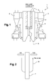
Figure 1 is a vertical, cross-sectional view of a circulating fluidized bed boiler of the invention, -
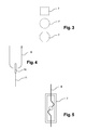
Figure 2 is a partial vertical section view of the boiler, -
Figure 3 is a partial horizontal section view of the boiler, -
Figure 4 is a partial vertical section view of the boiler, -
Figure 5 is a partial horizontal section view of the boiler -
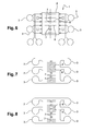
Figure 6 is a partial horizontal section view of a first embodiment, -
Figure 7 is a partial horizontal section view of a second embodiment, and -
Figure 8 is a partial horizontal section view of a third embodiment. -
Figure 1 illustrates a fluidized bed reactor having an exemplary structure according to the present invention. The main parts of theboiler 1 are thefurnace 2 and theparticle separators 3. Thefurnace 2 is defined byside walls 4, abottom 5 and aroof 6. Thefurnace 2 is provided with ports for feeding fuel and other bed material, e.g. sand and limestone. Thebottom 5 of thefurnace 2 is provided with means for supplying air for fluidizing the bed material. The lower portion of thefurnace 2 is also provided with ducts for supplying secondary air. - By means of the air deliveries to the
boiler 1 the combustion of fuel is maintained. Ash and bed material are discharged together with the fluidizing air and flue gases through ducts to theseparators 3, where most part of the solid material is separated from the flue gases and returned through a return pipe to the lower portion of thefurnace 2. - The
side walls 4 of the furnace can be formed of tube panels consisting of finned tubes not shown in detail in the figure. The energy released from the combustion of fuel is used for vaporizing the water flowing in the tubes of theside walls 4. - Inside the furnace there are
chambers 7, for instance gas-tight chambers, made of tube walls extending from thebottom 5 of thefurnace 2 to the top thereof. The walls of thechambers 7 are made of tube panels, the tubes of which are joined to feed pipes below the furnace and to header pipes above the furnace. Inside thechambers 7 there are preferably means for supplying secondary air and fuel to the center part of thefurnace 2. Thechambers 7 can be spaced away from theside walls 4 and arranged separately within thefurnace 2, for the furnace volume to be free for the particles to move even in the proximity ofsaid chambers 7. - The
chambers 7 can extend from thebottom 5 of thefurnace 2, or, as illustrated infigure 1 , can extend from an inclined wall of a pant-leg configuration, i.e. a configuration in which inclined walls extend upwards thebottom 5. The pant-leg design is typical for higher capacity boilers because it allows for better secondary air penetration, maintaining good air-coal mixing as well as efficient combustion. The pant-leg structured CFB boiler features two separated legs with solid particles fluidized by independent primary air supplies. - The possible shapes of the
chambers 7 are illustrated infigure 3 . The cross-section of the chambers can be a rectangle, a circle or a polygon. - The
furnace 2 further includesU-shaped panels 8 made of tubes and which are heating or superheating surfaces. Thepanels 8 are supported by headers located above theroof 6. In addition, the bottoms of thepanels 8 are fixed to thechambers 7. This fixation makes it possible to prevent horizontal displacements of the bottom part of thepanels 8. - As illustrated in
Figure 2 , everyU-shaped panel 8 can be constituted of two L-shaped parts that are each fixed at a wall of achamber 7. - The free space inside the box can be used for implementing a
bottle 10 to drain the condensates during the start-up of the boiler. Adrain pipe 11 is fitted to the bottom of thebottle 10 to evacuate the condensates (Figure 4 ). - As the
U-shaped panel 8 is fixed to thechamber 7 over two different zones, the tubes of thepanel 8 can be bended inside the box to make up for the difference of thermal expansion between thechamber 7 and thepanel 8. As illustrated inFigure 5 , the tubes can enter and leave the chamber in a direction parallel to the longitudinal axe of the rectangle, the tubes having a first bended portion on one side of the longitudinal axe followed by a second bended portion on the other side of the longitudinal axe. For instance, the tubes can have an inlet portion that is parallel to the longitudinal axe of the rectangle, followed by a first bended portion deflecting from the longitudinal axe on one side (for instance on the left-hand side), followed by a second bended portion deflecting from the longitudinal axe on the other side (on the right-hand side), followed by an outlet portion that is parallel to the longitudinal axe of the rectangle. The inlet portion and the first bended portion can be located in one half length of the rectangle whereas the second bended portion and the outlet portion can be located in the other half length of the rectangle. -
Figure 6 - illustrates a first embodiment of the
boiler 1. In this embodiment, everypanel 8 is connected to achamber 7 along with a dual grate design. - According to a second embodiment,
panels 8 connected tochambers 7 alternate with panels 9 which are not connected to a chamber (Figure 7 ). - As illustrated in
Figure 8 , and according to a third embodiment,several panels 8 are connected to eachchamber 7.
Claims (12)
- A circulating fluidized bed boiler (1) comprising a combustion chamber (2), characterized in that the combustion chamber (2) comprises:- first heat transfer surfaces (7) forming at least one vertical chamber extending from a lower part (5) of the combustion chamber (2), and- second heat transfer surfaces (8) having an inlet part and an outlet part which extend both from an upper part (6) of the combustion chamber (2), said second heat transfer surfaces (8) being fixed to vertical chambers (7).
- A boiler (1) according to claim 1, characterized in that every vertical chamber (7) is made of gastight panels formed with finned tubes and in that every second heat transfer surface (8) is made of tube panels.
- A boiler (1) according to claim 1 or 2, characterized in that each second heat transfer surface (8) is U-shaped.
- A boiler (1) according to any of claim 1 to 3, characterized in that the combustion chamber (2) is defined by side walls (4), a roof (6) and a bottom (5), and in that the first heat transfer surfaces (7) extend from the bottom (5) or from inclined walls joining the bottom (5) and in that the second heat transfer surfaces (8) extend from the roof (6) of the combustion chamber (2).
- A boiler (1) according to claim 3 or 4, characterized in that every U-shaped second heat transfer surface (8) comprises two vertical parts that are fixed at its lower extremity to a vertical chamber (7).
- A boiler (1) according to any of claim 3 to 5, characterized in that each U-shaped second heat transfer surface (8) extends downwards at least 40% of the height of the combustion chamber (2).
- A boiler (1) according to any of claim 1 to 6, characterized in that several second heat transfer surfaces (8) are fixed to the same vertical chamber (7).
- A boiler (1) according to any of claim 1 to 7, characterized in that every second heat transfer surface (8) passes through the vertical chamber (7).
- A boiler (1) according to claim 8, characterized in that the part of the second heat transfer surface (8) that is located inside the vertical chamber (7) comprises at least one bended portion.
- A boiler (1) according to claim 9, characterized in that second heat
transfer surface (8) is made of tube panels, the tubes entering and leaving the vertical chamber (7) in a direction parallel to a vertical axis of symmetry of the second heat transfer surface and in that the tubes have a first bended portion on one side of the axis of symmetry followed by a second bended portion on the other side of the axis of symmetry. - A boiler (1) according to claim 10, characterized in that the horizontal
cross-section of the vertical chamber (7) is a polygon or a circle. - A boiler (1) according to any of claim 1 to 11, characterized in that
every second heat transfer surface (8) comprises a bottle (10) for draining the condensates during the start-up of the boiler (1).
Priority Applications (12)
| Application Number | Priority Date | Filing Date | Title |
|---|---|---|---|
| RS20170918A RS56360B1 (en) | 2012-03-20 | 2012-03-20 | Circulating fluidized bed boiler |
| EP12160406.0A EP2642199B1 (en) | 2012-03-20 | 2012-03-20 | Circulating fluidized bed boiler |
| ES12160406.0T ES2637364T3 (en) | 2012-03-20 | 2012-03-20 | Circulating fluidized bed boiler |
| HUE12160406A HUE036292T2 (en) | 2012-03-20 | 2012-03-20 | Circulating fluidized bed boiler |
| PL12160406T PL2642199T3 (en) | 2012-03-20 | 2012-03-20 | Circulating fluidized bed boiler |
| MX2014010477A MX350268B (en) | 2012-03-20 | 2013-03-19 | Circulating fluidized bed boiler. |
| CN201380015451.6A CN104204666B (en) | 2012-03-20 | 2013-03-19 | Cfbb |
| KR1020147029016A KR102052140B1 (en) | 2012-03-20 | 2013-03-19 | Circulating fluidized bed boiler |
| IN7826DEN2014 IN2014DN07826A (en) | 2012-03-20 | 2013-03-19 | |
| PCT/IB2013/052166 WO2013140332A1 (en) | 2012-03-20 | 2013-03-19 | Circulating fluidized bed boiler |
| ZA2014/06404A ZA201406404B (en) | 2012-03-20 | 2014-09-01 | Circulating fluidized bed boiler |
| HRP20171409TT HRP20171409T1 (en) | 2012-03-20 | 2017-09-18 | Circulating fluidized bed boiler |
Applications Claiming Priority (1)
| Application Number | Priority Date | Filing Date | Title |
|---|---|---|---|
| EP12160406.0A EP2642199B1 (en) | 2012-03-20 | 2012-03-20 | Circulating fluidized bed boiler |
Publications (2)
| Publication Number | Publication Date |
|---|---|
| EP2642199A1 true EP2642199A1 (en) | 2013-09-25 |
| EP2642199B1 EP2642199B1 (en) | 2017-06-21 |
Family
ID=48325805
Family Applications (1)
| Application Number | Title | Priority Date | Filing Date |
|---|---|---|---|
| EP12160406.0A Active EP2642199B1 (en) | 2012-03-20 | 2012-03-20 | Circulating fluidized bed boiler |
Country Status (12)
| Country | Link |
|---|---|
| EP (1) | EP2642199B1 (en) |
| KR (1) | KR102052140B1 (en) |
| CN (1) | CN104204666B (en) |
| ES (1) | ES2637364T3 (en) |
| HR (1) | HRP20171409T1 (en) |
| HU (1) | HUE036292T2 (en) |
| IN (1) | IN2014DN07826A (en) |
| MX (1) | MX350268B (en) |
| PL (1) | PL2642199T3 (en) |
| RS (1) | RS56360B1 (en) |
| WO (1) | WO2013140332A1 (en) |
| ZA (1) | ZA201406404B (en) |
Cited By (2)
| Publication number | Priority date | Publication date | Assignee | Title |
|---|---|---|---|---|
| CN104848230A (en) * | 2015-05-31 | 2015-08-19 | 北京四维天拓技术有限公司 | Cyclone incinerator |
| CN114811576A (en) * | 2022-05-03 | 2022-07-29 | 浙江大学 | Large-scale CFB double-hearth boiler communication equipment |
Families Citing this family (2)
| Publication number | Priority date | Publication date | Assignee | Title |
|---|---|---|---|---|
| CN104728856B (en) * | 2013-12-20 | 2017-03-01 | 中国科学院工程热物理研究所 | Interdigitated electrode structure water-cooled column and the burner hearth with this water-cooled column |
| CN106402848B (en) * | 2016-12-05 | 2018-08-14 | 大连科林能源工程技术开发有限公司 | A kind of low dust-laden hot wind generating system of coalification industry environment-friendly type large capacity high temperature and pressure |
Citations (4)
| Publication number | Priority date | Publication date | Assignee | Title |
|---|---|---|---|---|
| WO1992011499A1 (en) * | 1990-12-21 | 1992-07-09 | A. Ahlstrom Corporation | Method and apparatus for controlling temperature in a circulating fluidized bed reactor |
| US6470833B1 (en) * | 1998-11-20 | 2002-10-29 | Foster Wheeler Energia Oy | Method and apparatus in a fluidized bed reactor |
| US20060124077A1 (en) * | 2002-11-22 | 2006-06-15 | Gerhard Weissinger | Continuous steam generator with circulating atmospheric fluidised-bed combustion |
| US20090084293A1 (en) * | 2005-04-26 | 2009-04-02 | Jean-Xavier Morin | Double Wall Extension |
Family Cites Families (2)
| Publication number | Priority date | Publication date | Assignee | Title |
|---|---|---|---|---|
| FR2837561B1 (en) * | 2002-03-25 | 2004-05-21 | Alstom Switzerland Ltd | FLUIDIZED BED BOILER FIREPLACE COMPRISING TWO FLOORS SEPARATED BY A CRACK |
| CN101818894B (en) * | 2010-04-29 | 2011-10-26 | 清华大学 | Circulating fluidized bed boiler |
-
2012
- 2012-03-20 ES ES12160406.0T patent/ES2637364T3/en active Active
- 2012-03-20 PL PL12160406T patent/PL2642199T3/en unknown
- 2012-03-20 RS RS20170918A patent/RS56360B1/en unknown
- 2012-03-20 HU HUE12160406A patent/HUE036292T2/en unknown
- 2012-03-20 EP EP12160406.0A patent/EP2642199B1/en active Active
-
2013
- 2013-03-19 IN IN7826DEN2014 patent/IN2014DN07826A/en unknown
- 2013-03-19 KR KR1020147029016A patent/KR102052140B1/en not_active Expired - Fee Related
- 2013-03-19 WO PCT/IB2013/052166 patent/WO2013140332A1/en not_active Ceased
- 2013-03-19 CN CN201380015451.6A patent/CN104204666B/en not_active Expired - Fee Related
- 2013-03-19 MX MX2014010477A patent/MX350268B/en active IP Right Grant
-
2014
- 2014-09-01 ZA ZA2014/06404A patent/ZA201406404B/en unknown
-
2017
- 2017-09-18 HR HRP20171409TT patent/HRP20171409T1/en unknown
Patent Citations (4)
| Publication number | Priority date | Publication date | Assignee | Title |
|---|---|---|---|---|
| WO1992011499A1 (en) * | 1990-12-21 | 1992-07-09 | A. Ahlstrom Corporation | Method and apparatus for controlling temperature in a circulating fluidized bed reactor |
| US6470833B1 (en) * | 1998-11-20 | 2002-10-29 | Foster Wheeler Energia Oy | Method and apparatus in a fluidized bed reactor |
| US20060124077A1 (en) * | 2002-11-22 | 2006-06-15 | Gerhard Weissinger | Continuous steam generator with circulating atmospheric fluidised-bed combustion |
| US20090084293A1 (en) * | 2005-04-26 | 2009-04-02 | Jean-Xavier Morin | Double Wall Extension |
Cited By (3)
| Publication number | Priority date | Publication date | Assignee | Title |
|---|---|---|---|---|
| CN104848230A (en) * | 2015-05-31 | 2015-08-19 | 北京四维天拓技术有限公司 | Cyclone incinerator |
| CN104848230B (en) * | 2015-05-31 | 2017-01-25 | 北京四维天拓技术有限公司 | Cyclone incinerator |
| CN114811576A (en) * | 2022-05-03 | 2022-07-29 | 浙江大学 | Large-scale CFB double-hearth boiler communication equipment |
Also Published As
| Publication number | Publication date |
|---|---|
| ES2637364T3 (en) | 2017-10-13 |
| WO2013140332A1 (en) | 2013-09-26 |
| EP2642199B1 (en) | 2017-06-21 |
| IN2014DN07826A (en) | 2015-05-15 |
| KR20140138298A (en) | 2014-12-03 |
| HRP20171409T1 (en) | 2017-11-03 |
| KR102052140B1 (en) | 2019-12-05 |
| PL2642199T3 (en) | 2017-11-30 |
| RS56360B1 (en) | 2017-12-29 |
| ZA201406404B (en) | 2016-08-31 |
| MX350268B (en) | 2017-08-31 |
| MX2014010477A (en) | 2015-04-08 |
| HUE036292T2 (en) | 2018-06-28 |
| CN104204666A (en) | 2014-12-10 |
| CN104204666B (en) | 2017-10-24 |
Similar Documents
| Publication | Publication Date | Title |
|---|---|---|
| KR101485477B1 (en) | Circulating fluidized bed boiler having two external heat exchanger for hot solids flow | |
| CN215982516U (en) | Wall of ring-sealed heat exchanger | |
| EP2642199B1 (en) | Circulating fluidized bed boiler | |
| KR101147722B1 (en) | Evaporator surface structure of a circulating fluidized bed boiler and a circulating fluidized bed boiler with such an evaporator surface structure | |
| EP1141626B1 (en) | Fluidized bed reactor | |
| KR101728273B1 (en) | A fluidized bed boiler | |
| PL173605B1 (en) | Method of and apparatus for starting a circulating fluidized bed system | |
| EP2884169B1 (en) | Fluidized bed apparatus | |
| CN100396991C (en) | Continuous Steam Generator with Circulating Atmospheric Fluidized Bed Combustion | |
| US20160356488A1 (en) | Fluidized Bed Apparatus and its Components | |
| EP2884163B1 (en) | Fluidized bed apparatus with a fluidized bed heat exchanger | |
| RU2495712C2 (en) | Boiling bed reactor | |
| CN116685805B (en) | Circulating fluidized bed boiler | |
| EP2539635A1 (en) | Fluidized bed reactor arrangement | |
| EP2884172A1 (en) | Fluidized bed syphon | |
| EP2884170A1 (en) | Fluidized bed apparatus | |
| EP2884164A1 (en) | Fluidized bed heat exchanger | |
| CN103168199A (en) | Wall construction for a boiler arrangement | |
| EP3054215B1 (en) | Fluidized bed heat exchanger | |
| JPH03102101A (en) | Fluid bed steam generator including steam cooling cyclone separator | |
| EP2884165A1 (en) | Fluidized bed heat exchanger | |
| EP2884168A1 (en) | Fluidized bed apparatus and mounting components | |
| EP2884167A1 (en) | Fluidized bed apparatus |
Legal Events
| Date | Code | Title | Description |
|---|---|---|---|
| PUAI | Public reference made under article 153(3) epc to a published international application that has entered the european phase |
Free format text: ORIGINAL CODE: 0009012 |
|
| AK | Designated contracting states |
Kind code of ref document: A1 Designated state(s): AL AT BE BG CH CY CZ DE DK EE ES FI FR GB GR HR HU IE IS IT LI LT LU LV MC MK MT NL NO PL PT RO RS SE SI SK SM TR |
|
| AX | Request for extension of the european patent |
Extension state: BA ME |
|
| 17P | Request for examination filed |
Effective date: 20131024 |
|
| RBV | Designated contracting states (corrected) |
Designated state(s): AL AT BE BG CH CY CZ DE DK EE ES FI FR GB GR HR HU IE IS IT LI LT LU LV MC MK MT NL NO PL PT RO RS SE SI SK SM TR |
|
| RAX | Requested extension states of the european patent have changed |
Extension state: ME Extension state: BA Payment date: 20140521 |
|
| RAP1 | Party data changed (applicant data changed or rights of an application transferred) |
Owner name: GENERAL ELECTRIC TECHNOLOGY GMBH |
|
| GRAP | Despatch of communication of intention to grant a patent |
Free format text: ORIGINAL CODE: EPIDOSNIGR1 |
|
| INTG | Intention to grant announced |
Effective date: 20161222 |
|
| GRAS | Grant fee paid |
Free format text: ORIGINAL CODE: EPIDOSNIGR3 |
|
| GRAJ | Information related to disapproval of communication of intention to grant by the applicant or resumption of examination proceedings by the epo deleted |
Free format text: ORIGINAL CODE: EPIDOSDIGR1 |
|
| GRAL | Information related to payment of fee for publishing/printing deleted |
Free format text: ORIGINAL CODE: EPIDOSDIGR3 |
|
| GRAR | Information related to intention to grant a patent recorded |
Free format text: ORIGINAL CODE: EPIDOSNIGR71 |
|
| INTC | Intention to grant announced (deleted) | ||
| GRAA | (expected) grant |
Free format text: ORIGINAL CODE: 0009210 |
|
| AK | Designated contracting states |
Kind code of ref document: B1 Designated state(s): AL AT BE BG CH CY CZ DE DK EE ES FI FR GB GR HR HU IE IS IT LI LT LU LV MC MK MT NL NO PL PT RO RS SE SI SK SM TR |
|
| AX | Request for extension of the european patent |
Extension state: BA |
|
| INTG | Intention to grant announced |
Effective date: 20170512 |
|
| REG | Reference to a national code |
Ref country code: GB Ref legal event code: FG4D |
|
| REG | Reference to a national code |
Ref country code: CH Ref legal event code: EP |
|
| REG | Reference to a national code |
Ref country code: IE Ref legal event code: FG4D |
|
| REG | Reference to a national code |
Ref country code: AT Ref legal event code: REF Ref document number: 903299 Country of ref document: AT Kind code of ref document: T Effective date: 20170715 |
|
| REG | Reference to a national code |
Ref country code: DE Ref legal event code: R096 Ref document number: 602012033619 Country of ref document: DE |
|
| REG | Reference to a national code |
Ref country code: RO Ref legal event code: EPE |
|
| REG | Reference to a national code |
Ref country code: HR Ref legal event code: TUEP Ref document number: P20171409 Country of ref document: HR |
|
| REG | Reference to a national code |
Ref country code: ES Ref legal event code: FG2A Ref document number: 2637364 Country of ref document: ES Kind code of ref document: T3 Effective date: 20171013 |
|
| REG | Reference to a national code |
Ref country code: NL Ref legal event code: MP Effective date: 20170621 |
|
| PG25 | Lapsed in a contracting state [announced via postgrant information from national office to epo] |
Ref country code: FI Free format text: LAPSE BECAUSE OF FAILURE TO SUBMIT A TRANSLATION OF THE DESCRIPTION OR TO PAY THE FEE WITHIN THE PRESCRIBED TIME-LIMIT Effective date: 20170621 Ref country code: NO Free format text: LAPSE BECAUSE OF FAILURE TO SUBMIT A TRANSLATION OF THE DESCRIPTION OR TO PAY THE FEE WITHIN THE PRESCRIBED TIME-LIMIT Effective date: 20170921 Ref country code: GR Free format text: LAPSE BECAUSE OF FAILURE TO SUBMIT A TRANSLATION OF THE DESCRIPTION OR TO PAY THE FEE WITHIN THE PRESCRIBED TIME-LIMIT Effective date: 20170922 Ref country code: LT Free format text: LAPSE BECAUSE OF FAILURE TO SUBMIT A TRANSLATION OF THE DESCRIPTION OR TO PAY THE FEE WITHIN THE PRESCRIBED TIME-LIMIT Effective date: 20170621 |
|
| REG | Reference to a national code |
Ref country code: HR Ref legal event code: T1PR Ref document number: P20171409 Country of ref document: HR |
|
| REG | Reference to a national code |
Ref country code: LT Ref legal event code: MG4D |
|
| REG | Reference to a national code |
Ref country code: AT Ref legal event code: MK05 Ref document number: 903299 Country of ref document: AT Kind code of ref document: T Effective date: 20170621 |
|
| PG25 | Lapsed in a contracting state [announced via postgrant information from national office to epo] |
Ref country code: LV Free format text: LAPSE BECAUSE OF FAILURE TO SUBMIT A TRANSLATION OF THE DESCRIPTION OR TO PAY THE FEE WITHIN THE PRESCRIBED TIME-LIMIT Effective date: 20170621 Ref country code: BG Free format text: LAPSE BECAUSE OF FAILURE TO SUBMIT A TRANSLATION OF THE DESCRIPTION OR TO PAY THE FEE WITHIN THE PRESCRIBED TIME-LIMIT Effective date: 20170921 Ref country code: NL Free format text: LAPSE BECAUSE OF FAILURE TO SUBMIT A TRANSLATION OF THE DESCRIPTION OR TO PAY THE FEE WITHIN THE PRESCRIBED TIME-LIMIT Effective date: 20170621 Ref country code: SE Free format text: LAPSE BECAUSE OF FAILURE TO SUBMIT A TRANSLATION OF THE DESCRIPTION OR TO PAY THE FEE WITHIN THE PRESCRIBED TIME-LIMIT Effective date: 20170621 |
|
| PG25 | Lapsed in a contracting state [announced via postgrant information from national office to epo] |
Ref country code: AT Free format text: LAPSE BECAUSE OF FAILURE TO SUBMIT A TRANSLATION OF THE DESCRIPTION OR TO PAY THE FEE WITHIN THE PRESCRIBED TIME-LIMIT Effective date: 20170621 Ref country code: CZ Free format text: LAPSE BECAUSE OF FAILURE TO SUBMIT A TRANSLATION OF THE DESCRIPTION OR TO PAY THE FEE WITHIN THE PRESCRIBED TIME-LIMIT Effective date: 20170621 Ref country code: EE Free format text: LAPSE BECAUSE OF FAILURE TO SUBMIT A TRANSLATION OF THE DESCRIPTION OR TO PAY THE FEE WITHIN THE PRESCRIBED TIME-LIMIT Effective date: 20170621 Ref country code: SK Free format text: LAPSE BECAUSE OF FAILURE TO SUBMIT A TRANSLATION OF THE DESCRIPTION OR TO PAY THE FEE WITHIN THE PRESCRIBED TIME-LIMIT Effective date: 20170621 |
|
| PG25 | Lapsed in a contracting state [announced via postgrant information from national office to epo] |
Ref country code: IS Free format text: LAPSE BECAUSE OF FAILURE TO SUBMIT A TRANSLATION OF THE DESCRIPTION OR TO PAY THE FEE WITHIN THE PRESCRIBED TIME-LIMIT Effective date: 20171021 Ref country code: IT Free format text: LAPSE BECAUSE OF FAILURE TO SUBMIT A TRANSLATION OF THE DESCRIPTION OR TO PAY THE FEE WITHIN THE PRESCRIBED TIME-LIMIT Effective date: 20170621 Ref country code: SM Free format text: LAPSE BECAUSE OF FAILURE TO SUBMIT A TRANSLATION OF THE DESCRIPTION OR TO PAY THE FEE WITHIN THE PRESCRIBED TIME-LIMIT Effective date: 20170621 |
|
| REG | Reference to a national code |
Ref country code: DE Ref legal event code: R097 Ref document number: 602012033619 Country of ref document: DE |
|
| PLBE | No opposition filed within time limit |
Free format text: ORIGINAL CODE: 0009261 |
|
| STAA | Information on the status of an ep patent application or granted ep patent |
Free format text: STATUS: NO OPPOSITION FILED WITHIN TIME LIMIT |
|
| PG25 | Lapsed in a contracting state [announced via postgrant information from national office to epo] |
Ref country code: DK Free format text: LAPSE BECAUSE OF FAILURE TO SUBMIT A TRANSLATION OF THE DESCRIPTION OR TO PAY THE FEE WITHIN THE PRESCRIBED TIME-LIMIT Effective date: 20170621 |
|
| 26N | No opposition filed |
Effective date: 20180322 |
|
| REG | Reference to a national code |
Ref country code: HU Ref legal event code: AG4A Ref document number: E036292 Country of ref document: HU |
|
| PG25 | Lapsed in a contracting state [announced via postgrant information from national office to epo] |
Ref country code: SI Free format text: LAPSE BECAUSE OF FAILURE TO SUBMIT A TRANSLATION OF THE DESCRIPTION OR TO PAY THE FEE WITHIN THE PRESCRIBED TIME-LIMIT Effective date: 20170621 |
|
| REG | Reference to a national code |
Ref country code: HR Ref legal event code: PBON Ref document number: P20171409 Country of ref document: HR Effective date: 20180320 |
|
| REG | Reference to a national code |
Ref country code: DE Ref legal event code: R119 Ref document number: 602012033619 Country of ref document: DE |
|
| REG | Reference to a national code |
Ref country code: CH Ref legal event code: PL |
|
| GBPC | Gb: european patent ceased through non-payment of renewal fee |
Effective date: 20180320 |
|
| PG25 | Lapsed in a contracting state [announced via postgrant information from national office to epo] |
Ref country code: MC Free format text: LAPSE BECAUSE OF FAILURE TO SUBMIT A TRANSLATION OF THE DESCRIPTION OR TO PAY THE FEE WITHIN THE PRESCRIBED TIME-LIMIT Effective date: 20170621 Ref country code: RS Free format text: LAPSE BECAUSE OF NON-PAYMENT OF DUE FEES Effective date: 20180924 |
|
| REG | Reference to a national code |
Ref country code: BE Ref legal event code: MM Effective date: 20180331 |
|
| REG | Reference to a national code |
Ref country code: IE Ref legal event code: MM4A |
|
| PG25 | Lapsed in a contracting state [announced via postgrant information from national office to epo] |
Ref country code: LU Free format text: LAPSE BECAUSE OF NON-PAYMENT OF DUE FEES Effective date: 20180320 |
|
| PG25 | Lapsed in a contracting state [announced via postgrant information from national office to epo] |
Ref country code: IE Free format text: LAPSE BECAUSE OF NON-PAYMENT OF DUE FEES Effective date: 20180320 Ref country code: RO Free format text: LAPSE BECAUSE OF NON-PAYMENT OF DUE FEES Effective date: 20170621 Ref country code: DE Free format text: LAPSE BECAUSE OF NON-PAYMENT OF DUE FEES Effective date: 20181002 Ref country code: HU Free format text: LAPSE BECAUSE OF NON-PAYMENT OF DUE FEES Effective date: 20180321 |
|
| PG25 | Lapsed in a contracting state [announced via postgrant information from national office to epo] |
Ref country code: BE Free format text: LAPSE BECAUSE OF NON-PAYMENT OF DUE FEES Effective date: 20180331 Ref country code: CH Free format text: LAPSE BECAUSE OF NON-PAYMENT OF DUE FEES Effective date: 20180331 Ref country code: LI Free format text: LAPSE BECAUSE OF NON-PAYMENT OF DUE FEES Effective date: 20180331 Ref country code: GB Free format text: LAPSE BECAUSE OF NON-PAYMENT OF DUE FEES Effective date: 20180320 Ref country code: HR Free format text: LAPSE BECAUSE OF NON-PAYMENT OF DUE FEES Effective date: 20180320 |
|
| PG25 | Lapsed in a contracting state [announced via postgrant information from national office to epo] |
Ref country code: FR Free format text: LAPSE BECAUSE OF NON-PAYMENT OF DUE FEES Effective date: 20180331 |
|
| REG | Reference to a national code |
Ref country code: ES Ref legal event code: FD2A Effective date: 20190903 |
|
| PG25 | Lapsed in a contracting state [announced via postgrant information from national office to epo] |
Ref country code: ES Free format text: LAPSE BECAUSE OF NON-PAYMENT OF DUE FEES Effective date: 20180321 |
|
| PG25 | Lapsed in a contracting state [announced via postgrant information from national office to epo] |
Ref country code: MT Free format text: LAPSE BECAUSE OF NON-PAYMENT OF DUE FEES Effective date: 20180320 |
|
| PGFP | Annual fee paid to national office [announced via postgrant information from national office to epo] |
Ref country code: PL Payment date: 20200220 Year of fee payment: 9 |
|
| PG25 | Lapsed in a contracting state [announced via postgrant information from national office to epo] |
Ref country code: PT Free format text: LAPSE BECAUSE OF FAILURE TO SUBMIT A TRANSLATION OF THE DESCRIPTION OR TO PAY THE FEE WITHIN THE PRESCRIBED TIME-LIMIT Effective date: 20170621 |
|
| PG25 | Lapsed in a contracting state [announced via postgrant information from national office to epo] |
Ref country code: CY Free format text: LAPSE BECAUSE OF FAILURE TO SUBMIT A TRANSLATION OF THE DESCRIPTION OR TO PAY THE FEE WITHIN THE PRESCRIBED TIME-LIMIT Effective date: 20170621 Ref country code: MK Free format text: LAPSE BECAUSE OF NON-PAYMENT OF DUE FEES Effective date: 20170621 |
|
| PG25 | Lapsed in a contracting state [announced via postgrant information from national office to epo] |
Ref country code: AL Free format text: LAPSE BECAUSE OF FAILURE TO SUBMIT A TRANSLATION OF THE DESCRIPTION OR TO PAY THE FEE WITHIN THE PRESCRIBED TIME-LIMIT Effective date: 20170621 |
|
| PGFP | Annual fee paid to national office [announced via postgrant information from national office to epo] |
Ref country code: TR Payment date: 20210224 Year of fee payment: 10 |
|
| PG25 | Lapsed in a contracting state [announced via postgrant information from national office to epo] |
Ref country code: PL Free format text: LAPSE BECAUSE OF NON-PAYMENT OF DUE FEES Effective date: 20210320 |
|
| P01 | Opt-out of the competence of the unified patent court (upc) registered |
Effective date: 20230523 |