EP2642163A1 - Power transmission device for electric vehicle and production method therefor - Google Patents
Power transmission device for electric vehicle and production method therefor Download PDFInfo
- Publication number
- EP2642163A1 EP2642163A1 EP11840976.2A EP11840976A EP2642163A1 EP 2642163 A1 EP2642163 A1 EP 2642163A1 EP 11840976 A EP11840976 A EP 11840976A EP 2642163 A1 EP2642163 A1 EP 2642163A1
- Authority
- EP
- European Patent Office
- Prior art keywords
- brush
- cover
- power transmission
- axis
- sliding contact
- Prior art date
- Legal status (The legal status is an assumption and is not a legal conclusion. Google has not performed a legal analysis and makes no representation as to the accuracy of the status listed.)
- Granted
Links
Images





Classifications
-
- H—ELECTRICITY
- H02—GENERATION; CONVERSION OR DISTRIBUTION OF ELECTRIC POWER
- H02K—DYNAMO-ELECTRIC MACHINES
- H02K15/00—Processes or apparatus specially adapted for manufacturing, assembling, maintaining or repairing of dynamo-electric machines
-
- B—PERFORMING OPERATIONS; TRANSPORTING
- B60—VEHICLES IN GENERAL
- B60L—PROPULSION OF ELECTRICALLY-PROPELLED VEHICLES; SUPPLYING ELECTRIC POWER FOR AUXILIARY EQUIPMENT OF ELECTRICALLY-PROPELLED VEHICLES; ELECTRODYNAMIC BRAKE SYSTEMS FOR VEHICLES IN GENERAL; MAGNETIC SUSPENSION OR LEVITATION FOR VEHICLES; MONITORING OPERATING VARIABLES OF ELECTRICALLY-PROPELLED VEHICLES; ELECTRIC SAFETY DEVICES FOR ELECTRICALLY-PROPELLED VEHICLES
- B60L50/00—Electric propulsion with power supplied within the vehicle
- B60L50/50—Electric propulsion with power supplied within the vehicle using propulsion power supplied by batteries or fuel cells
- B60L50/51—Electric propulsion with power supplied within the vehicle using propulsion power supplied by batteries or fuel cells characterised by AC-motors
-
- B—PERFORMING OPERATIONS; TRANSPORTING
- B60—VEHICLES IN GENERAL
- B60L—PROPULSION OF ELECTRICALLY-PROPELLED VEHICLES; SUPPLYING ELECTRIC POWER FOR AUXILIARY EQUIPMENT OF ELECTRICALLY-PROPELLED VEHICLES; ELECTRODYNAMIC BRAKE SYSTEMS FOR VEHICLES IN GENERAL; MAGNETIC SUSPENSION OR LEVITATION FOR VEHICLES; MONITORING OPERATING VARIABLES OF ELECTRICALLY-PROPELLED VEHICLES; ELECTRIC SAFETY DEVICES FOR ELECTRICALLY-PROPELLED VEHICLES
- B60L7/00—Electrodynamic brake systems for vehicles in general
- B60L7/10—Dynamic electric regenerative braking
- B60L7/14—Dynamic electric regenerative braking for vehicles propelled by AC motors
-
- H—ELECTRICITY
- H02—GENERATION; CONVERSION OR DISTRIBUTION OF ELECTRIC POWER
- H02K—DYNAMO-ELECTRIC MACHINES
- H02K11/00—Structural association of dynamo-electric machines with electric components or with devices for shielding, monitoring or protection
- H02K11/40—Structural association with grounding devices
-
- H—ELECTRICITY
- H02—GENERATION; CONVERSION OR DISTRIBUTION OF ELECTRIC POWER
- H02K—DYNAMO-ELECTRIC MACHINES
- H02K13/00—Structural associations of current collectors with motors or generators, e.g. brush mounting plates or connections to windings; Disposition of current collectors in motors or generators; Arrangements for improving commutation
- H02K13/003—Structural associations of slip-rings
-
- H—ELECTRICITY
- H02—GENERATION; CONVERSION OR DISTRIBUTION OF ELECTRIC POWER
- H02K—DYNAMO-ELECTRIC MACHINES
- H02K5/00—Casings; Enclosures; Supports
- H02K5/04—Casings or enclosures characterised by the shape, form or construction thereof
- H02K5/14—Means for supporting or protecting brushes or brush holders
- H02K5/143—Means for supporting or protecting brushes or brush holders for cooperation with commutators
- H02K5/148—Slidably supported brushes
-
- H—ELECTRICITY
- H02—GENERATION; CONVERSION OR DISTRIBUTION OF ELECTRIC POWER
- H02K—DYNAMO-ELECTRIC MACHINES
- H02K5/00—Casings; Enclosures; Supports
- H02K5/04—Casings or enclosures characterised by the shape, form or construction thereof
- H02K5/15—Mounting arrangements for bearing-shields or end plates
-
- B—PERFORMING OPERATIONS; TRANSPORTING
- B60—VEHICLES IN GENERAL
- B60L—PROPULSION OF ELECTRICALLY-PROPELLED VEHICLES; SUPPLYING ELECTRIC POWER FOR AUXILIARY EQUIPMENT OF ELECTRICALLY-PROPELLED VEHICLES; ELECTRODYNAMIC BRAKE SYSTEMS FOR VEHICLES IN GENERAL; MAGNETIC SUSPENSION OR LEVITATION FOR VEHICLES; MONITORING OPERATING VARIABLES OF ELECTRICALLY-PROPELLED VEHICLES; ELECTRIC SAFETY DEVICES FOR ELECTRICALLY-PROPELLED VEHICLES
- B60L2220/00—Electrical machine types; Structures or applications thereof
- B60L2220/10—Electrical machine types
- B60L2220/14—Synchronous machines
-
- B—PERFORMING OPERATIONS; TRANSPORTING
- B60—VEHICLES IN GENERAL
- B60L—PROPULSION OF ELECTRICALLY-PROPELLED VEHICLES; SUPPLYING ELECTRIC POWER FOR AUXILIARY EQUIPMENT OF ELECTRICALLY-PROPELLED VEHICLES; ELECTRODYNAMIC BRAKE SYSTEMS FOR VEHICLES IN GENERAL; MAGNETIC SUSPENSION OR LEVITATION FOR VEHICLES; MONITORING OPERATING VARIABLES OF ELECTRICALLY-PROPELLED VEHICLES; ELECTRIC SAFETY DEVICES FOR ELECTRICALLY-PROPELLED VEHICLES
- B60L2240/00—Control parameters of input or output; Target parameters
- B60L2240/10—Vehicle control parameters
- B60L2240/12—Speed
-
- B—PERFORMING OPERATIONS; TRANSPORTING
- B60—VEHICLES IN GENERAL
- B60L—PROPULSION OF ELECTRICALLY-PROPELLED VEHICLES; SUPPLYING ELECTRIC POWER FOR AUXILIARY EQUIPMENT OF ELECTRICALLY-PROPELLED VEHICLES; ELECTRODYNAMIC BRAKE SYSTEMS FOR VEHICLES IN GENERAL; MAGNETIC SUSPENSION OR LEVITATION FOR VEHICLES; MONITORING OPERATING VARIABLES OF ELECTRICALLY-PROPELLED VEHICLES; ELECTRIC SAFETY DEVICES FOR ELECTRICALLY-PROPELLED VEHICLES
- B60L2270/00—Problem solutions or means not otherwise provided for
- B60L2270/10—Emission reduction
- B60L2270/14—Emission reduction of noise
- B60L2270/147—Emission reduction of noise electro magnetic [EMI]
-
- H—ELECTRICITY
- H01—ELECTRIC ELEMENTS
- H01R—ELECTRICALLY-CONDUCTIVE CONNECTIONS; STRUCTURAL ASSOCIATIONS OF A PLURALITY OF MUTUALLY-INSULATED ELECTRICAL CONNECTING ELEMENTS; COUPLING DEVICES; CURRENT COLLECTORS
- H01R43/00—Apparatus or processes specially adapted for manufacturing, assembling, maintaining, or repairing of line connectors or current collectors or for joining electric conductors
- H01R43/12—Manufacture of brushes
-
- H—ELECTRICITY
- H02—GENERATION; CONVERSION OR DISTRIBUTION OF ELECTRIC POWER
- H02K—DYNAMO-ELECTRIC MACHINES
- H02K2205/00—Specific aspects not provided for in the other groups of this subclass relating to casings, enclosures, supports
- H02K2205/06—Machines characterised by means for keeping the brushes in a retracted position during assembly
-
- H—ELECTRICITY
- H02—GENERATION; CONVERSION OR DISTRIBUTION OF ELECTRIC POWER
- H02K—DYNAMO-ELECTRIC MACHINES
- H02K7/00—Arrangements for handling mechanical energy structurally associated with dynamo-electric machines, e.g. structural association with mechanical driving motors or auxiliary dynamo-electric machines
- H02K7/10—Structural association with clutches, brakes, gears, pulleys or mechanical starters
- H02K7/116—Structural association with clutches, brakes, gears, pulleys or mechanical starters with gears
-
- Y—GENERAL TAGGING OF NEW TECHNOLOGICAL DEVELOPMENTS; GENERAL TAGGING OF CROSS-SECTIONAL TECHNOLOGIES SPANNING OVER SEVERAL SECTIONS OF THE IPC; TECHNICAL SUBJECTS COVERED BY FORMER USPC CROSS-REFERENCE ART COLLECTIONS [XRACs] AND DIGESTS
- Y02—TECHNOLOGIES OR APPLICATIONS FOR MITIGATION OR ADAPTATION AGAINST CLIMATE CHANGE
- Y02T—CLIMATE CHANGE MITIGATION TECHNOLOGIES RELATED TO TRANSPORTATION
- Y02T10/00—Road transport of goods or passengers
- Y02T10/60—Other road transportation technologies with climate change mitigation effect
- Y02T10/64—Electric machine technologies in electromobility
-
- Y—GENERAL TAGGING OF NEW TECHNOLOGICAL DEVELOPMENTS; GENERAL TAGGING OF CROSS-SECTIONAL TECHNOLOGIES SPANNING OVER SEVERAL SECTIONS OF THE IPC; TECHNICAL SUBJECTS COVERED BY FORMER USPC CROSS-REFERENCE ART COLLECTIONS [XRACs] AND DIGESTS
- Y02—TECHNOLOGIES OR APPLICATIONS FOR MITIGATION OR ADAPTATION AGAINST CLIMATE CHANGE
- Y02T—CLIMATE CHANGE MITIGATION TECHNOLOGIES RELATED TO TRANSPORTATION
- Y02T10/00—Road transport of goods or passengers
- Y02T10/60—Other road transportation technologies with climate change mitigation effect
- Y02T10/70—Energy storage systems for electromobility, e.g. batteries
-
- Y—GENERAL TAGGING OF NEW TECHNOLOGICAL DEVELOPMENTS; GENERAL TAGGING OF CROSS-SECTIONAL TECHNOLOGIES SPANNING OVER SEVERAL SECTIONS OF THE IPC; TECHNICAL SUBJECTS COVERED BY FORMER USPC CROSS-REFERENCE ART COLLECTIONS [XRACs] AND DIGESTS
- Y02—TECHNOLOGIES OR APPLICATIONS FOR MITIGATION OR ADAPTATION AGAINST CLIMATE CHANGE
- Y02T—CLIMATE CHANGE MITIGATION TECHNOLOGIES RELATED TO TRANSPORTATION
- Y02T90/00—Enabling technologies or technologies with a potential or indirect contribution to GHG emissions mitigation
- Y02T90/10—Technologies relating to charging of electric vehicles
- Y02T90/16—Information or communication technologies improving the operation of electric vehicles
-
- Y—GENERAL TAGGING OF NEW TECHNOLOGICAL DEVELOPMENTS; GENERAL TAGGING OF CROSS-SECTIONAL TECHNOLOGIES SPANNING OVER SEVERAL SECTIONS OF THE IPC; TECHNICAL SUBJECTS COVERED BY FORMER USPC CROSS-REFERENCE ART COLLECTIONS [XRACs] AND DIGESTS
- Y10—TECHNICAL SUBJECTS COVERED BY FORMER USPC
- Y10T—TECHNICAL SUBJECTS COVERED BY FORMER US CLASSIFICATION
- Y10T29/00—Metal working
- Y10T29/49—Method of mechanical manufacture
- Y10T29/49002—Electrical device making
- Y10T29/49009—Dynamoelectric machine
Definitions
- the present invention relates to a power transmission deice for an electrically driven vehicle such as electric vehicle and a manufacturing method therefore, in which measures for suppression of high-frequency noise from an inverter are taken.
- the present invention has been made focusing on the above problems, and has the object to provide a power transmission device for an electrically driven vehicle and manufacturing method therefore, to prevent forgetting removal of the brush protective jig for protecting brush contacts when assembling a sliding contact brush contact, while improving workability at the time of slide brush installation and ensuring the radio noise reduction performance.
- the power transmission device for an electrically driven vehicle is provided with a power transmission mechanism, sliding contact brush, brush case cover, and brush protective jig.
- the power transmission mechanism is interposed between a motor shaft of a motor which is driven by an inverter and drive wheels, and is comprised of a case element, axis element, and power transmission element.
- the sliding contact brush is disposed on the axis end of the axis element, with one end thereof being maintained in contact with the axis end while the other end being grounded to a vehicle body.
- the brush case cover is mounted on a cover mount portion that encloses the axis end of the case element describe above and opens to form thereby a brush chamber accommodating the sliding contact brush.
- the brush protective jig is attached to cover the brush contact during assembly of the sliding contact brush to the axis end, and the brush protective jig or fixture is configured to have such a length by which, when mounting the brush case cover to the cover mount portion, the brush case cover would interfere with the brush case cover when the brush protective jig remains in an attached state.
- a power transmission mechanism which is interposed between a motor shaft of a motor driven by an inverter and drive wheels and having a case element, axis element, and power transmission element, wherein a process to assemble a sliding contact brush, a process to remove a brush protective jig, and a process to mount a brush case cover.
- the sliding contact brush is installed or assembled at the axis end position of the axis element with one end maintained contact with the axis end while the other end electrically grounded with respect to vehicle body.
- a brush protective jig is removed which is attached to cover the brush contact when installing the sliding contact brush to the axis end, and is configured to provide such a length by which, without being removed, the brush protective jig would conflict with the brush case cover.
- the brush case forming a brush chamber that accommodates the sliding contact brush is mounted to the cover mounting portion which encloses the axis end portion of the axis element in the case element and opens.
- the brush protective jig when assembling the sliding contact brush to the axis end of the axis element, the brush protective jig is attached over the brush contact of the sliding contact brush. Further, when mounting the brush case cover to the cover mounting portion, if the brush protective jig remains in an attached state, then the brush protective jig conflicts with the brush case cover. Therefore, unless the brush protective jig is removed, the brush case cover cannot be mounted to the cover mount portion so that the brush protective jig will be prevented from being forgotten to be removed or detached. Further, the brush protective jig is configured to have such an axial length to conflict with the brush case cover when the brush case cover is being mounted to the cover mount portion.
- the axial length of brush protective jig is set greater than the axial length of the sliding contact brush. Therefore, during attaching process to the sliding contact brush, the brush protective jig may be easily grasped and easy attachment or removal thereof to improve workability. As a result, during the time of installation or assembly of the sliding contact brush, while improving the workability, removal of brush protective jig for protecting the brush contact will be avoided to be forgotten, and performance regarding radio noise reduction will be secured.
- Fig. 1 is a schematic diagram showing an overall structure of a power transmission device for an electric vehicle (an example of power transmission device for an electrically driven vehicle). Overall structure or configuration is now described based on Fig. 1 .
- the power transmission device in the first embodiment for an electric vehicle is provided with a motor 1, an inverter 2, reduction gear mechanism 3 (power transmission mechanism), a power transmission coupling unit 4, and a sliding contact brush earth structure 5.
- the motor 1 is provided with a motor housing 1 a, motor shaft 1 b rotatably mounted on the motor housing 1 a, rotors 1 c fixed to motor shaft 1 b, stator 1 e with motor coils 1d wounded.
- a synchronous motor of embedded magnets is used and the rotor 1c has permanent magnet embedded therein.
- the inverter 2 is connected to motor coil 1 d of motor 1 via a three phase alternating current cable 6 while connected to a second battery 7 via a DC power cable 8.
- This inverter 2 has a function as a high-frequency controller for changing the direction of the current by the switching element. In a drive mode, DC current from the secondary battery 7 is converted to three-phase alternating current to the motor 1 while, at a regeneration, the three-phase AC from motor 1 will be converted to DC to the secondary battery 7.
- the reduction gear mechanism 3 is interposed between motor shaft 1 b and drive wheels 9, 9, and is a power transmission mechanism having a case element, shaft element and power transmission element.
- a gear case 3a accommodating the shaft element and power transmission element serves as the case element.
- As the shaft element an input shaft 3b, countershaft 3c, and output shafts 3d, 3d are included.
- the power transmission mechanism comprised of a gear train is provided with an input gear 3e, first counter gear 3f, second counter gear 3g, drive gear 3h, and differential gear 31.
- the power transmission coupling portion 4 is provided in a power transmission pathway from motor shaft 1 b to drive wheels 9, 9, and represents a resistance body imparting an electric resistance downstream of motor shaft 1 b.
- spline fitting portion 4a, coupling portions 4b, 4c, gear meshing portion 4d, 4e, and the like may be used as being previously provided in the power transmission pathway of the reduction gear mechanism 3 for imparting electric resistance.
- the spline fitting portion 4a is a portion at which motor shaft 1 b and input shaft 3b are connected via spline.
- the coupling portion 4b, 4b presents a coupling portion between output shafts 3d,3d of gear reduction mechanism 3 and drive shaft 3d', 3d' to drive wheels 9,9.
- the gear meshing portion 4d represents a meshing portion between input gear 3e and first counter gear 3f
- the gear meshing portion 4e is a meshing portion between second counter gear 3g and drive gear 3h.
- the sliding contact brush ground structure 5 is a structure which connects electrically the position in the power transmission pathway at downstream of power transmission coupling portion 4 (spline fitting portion 4a, gear meshing portion 4d) as a resistance body with a vehicle body 10.
- This sliding contact brush ground structure 5 is provided with brush contact 5a, 5a, spring 5d, 5d, leads 5e, 5e, gear case 3a, and connecting line 5b.
- the brush contact 5a, 5a slides with the shaft end 3c' of countershaft 3c of reduction gear mechanism at the urging force of spring 5d, 5d.
- the lead 5e, 5e connects electrically brush contact 5a, 5a and gear case 3a.
- the connecting line 5b connects electrically gear case 3a and vehicle body 10.
- Fig. 1 , 11, 11 denote left and right suspensions, 12 denotes a breather hole.
- Figs. 2-4 show the setup portion of the sliding contact brush assembly 25 in a power transmission device for an electric vehicle in the first embodiment.
- Figs. 2-4 show the configuration of a setup portion of sliding contact brush assembly 25 is described..
- the countershaft 3c is rotatably supported on gear case 3a via ball bearing 13, and first counter gear 3f (see Fig. 1 ) is fitted by spline on the inner position of the bal bearing 13.
- first counter gear 3f (see Fig. 1 ) is fitted by spline on the inner position of the bal bearing 13.
- an oil seal 14 At the outside position of ball bearing 13 is provided an oil seal 14 on gear case 3a.
- a stopper 15 and a pair of brush contacts 5a, 5a are provided which represent an electrical connection position CP of the sliding contact brush assembly 25 in the electric power transmission pathway.
- the stopper 15 is provided, as shown in Figs. 2 and 3 , on shaft end 3c' at the step position located on the rear side of the pair of contact position of the brush contacts 5a, 5a.
- This stopper 15 is of collar member intended, when mounting the brush case cover 16 to cover mounting portion 19, to prevent the protective cover 20 (brush protective jig) from being pushed in a attached state as shown in Fig. 3 .
- brush case cover 16 As shown in Fig. 4 , shaft end 3c 'of the countershaft 3c is covered by the brush case cover 16. As shown in Fig. 3 , brush case cover 1 is mounted to cover mounting portion 19 enclosing the shaft end 3c' of gear case 3a to open via bolt 18. By mounting and fixing the brush case cover 16, as shown in Fig. 2 , a brush chamber 17 is formed in communication with interior chamber 3j of gear case 3a. Further, brush case cover 16 is formed with a breather hole 12 disposed on brush chamber 17, as shown in Fig. 4 .
- the pair of brush contact 5a, 5a has a slip ring surface formed by a cylindrical surface of shaft end 3c' of countershaft 3c.
- the brush contact 5a,5a are provided by pair within two receiving holes of brush holder 5c of insulating material with springs 5a, 5a and thus contact pressure may be held by springs 5d,5d. with maintaining contact with shaft end 3c' of countershaft 3c.
- the brush holder 5c has a case fixing plate 21 which is fixed to a case extension 3a' extending from gear case 3a via bolt 22.
- a pair of brush contacts 5a, 5a are disposed while maintaining contact with shaft end 3c' of the countershaft 3c.
- a pair of brush contacts 5a, 5a rest on spring seat 5f, 5f via spring 5d, 5d, and lead 5e,ed is connected to this spring seat 5f, 5f.
- the end of lead 5e, 5e is connected, as shown in Fig. 3 , to ground plate 23 provided with brush holder 5c by soldering.
- ground plate 23 is fixed to gear case 3a via screw 24.
- Figs. 5 and 6 respectively show a state in which the protective cover 20 is attached to the sliding contact brush assembly 25 in a power transmission device for an electric vehicle in the first embodiment.
- the following describes the slide structure of the protective cover 20 and the sliding contact brush assembly 25.
- the sliding contact brush assembly 25 is provided with brush holder 5c, lead 5e, 5e, case fixing plate 21, and ground plate 23, and is structured as a pre-assembled unit. Inside the brush holder 5c, as described above, brush contact 5a, 5a, spring 5d, 5d, and spring seat 5f, 5f are housed.
- the brush holder 5c comprises a pair of grooves 26, 26 extending axially at lower position of the surfaces of both sides sandwiching the end surfaces from which brush contact 5a, 5a projects.
- the protective cover 20 has a pair of slide pawls 27, 27 extending parallel to each other to engage with the pair of parallel slide grooves of brush holder 5c when mounting to brush holder 5c.
- Figs. 7-9 show a configuration of a protective cover 20 of the power transmission device for an electric vehicle in the first embodiment. The following describes the configuration of the protective cover 20.
- the protective cover 20 is provided with a main cover portion 28 covering the brush contact 5a, 5a, a pair of sub-cover portion 29 and 29 rising from both sides of the main cover portion, a pair of slide craws formed on the end portion of the sub-cover portion 29, 29.
- the feature of the protective cover resides in that, as shown in Fig. 8 , it is symmetrical with respect to an axial symmetry axis L1 as well as with respect to a symmetry axis L2 , a orthogonal direction relative to the axis.
- Figs. 10 and 11 show the axial dimensions of the setup portion of sliding contact brush in the power transmission device for an electric vehicle.
- the setting of axial dimension of the protective cover 2 is described.
- the protective cover 20 is a protective jig that is mounted or attached over the brush contacts 5a, 5a when assembling the brush assembly 25 to shaft end 3c '.
- the axial length L of the protective cover 20 is set to the length in such a way that, when mounting the brush case cover 1 to cover mounting portion 19, the protective cover would interfere with the brush case cover 16 when mounted to the mounting portion 19 if remained in the mounted state.
- a comparative example is set in which the electrical contact position of sliding contact brush is located at motor shaft and earthing is made or grounded to the vehicle body at the position of the electrical connection of the motor shaft .
- V1 motor side voltage
- Z8 earth resistance
- ZR upstream resistance
- the motor shaft may be grounded to the vehicle body, the position of grounding is at motor shaft.
- the inverter i.e., source of noise generation
- the distance between the source of noise generation (inverter) and the position of electrical contact for earthing (motor shaft) is short, and the upstream resistance ZR will be smaller. Therefore, reduction of output voltage V2 is of small margin, noise propagation occurs downstream in the drive shaft direction.
- a power transmission coupling portion 4 is provided in a power transmission path extending from the motor shaft 1 b to the drive wheels 9,9.
- the sliding contact brush ground structure 5 is electrically connected to vehicle body 10. Further, the positional relationship between power transmission coupling portion 4 and sliding contact brush ground structure 5 is such that the power transmission coupling portion 4 (resistance body) is provided downstream of motor shaft 1 b, and the position further downstream of the power transmission coupling portion 4 is set as the electrical connection position CP of sliding contact brush ground structure 5.
- the upstream side resistance ZR representing the upstream resistance of the electrical connection position CP of sliding contact brush ground structure 5 becomes larger, and as apparent from equation (1) described above, the output voltage V2 can be reduced. Therefore, the output voltage, V2 exiting downstream from the electrical connection position CP of sliding contact brush ground structure 5 is attenuated, and the noise propagated from upstream to downstream in the power transmission path is reduced.
- a power transmission coupling portion 4 is provided, and at the position further downstream of the power transmission coupling portion, an electrical connection position CP of sliding contact brush ground structure 5 is configured to be set. Consequently, it is possible, in an electric vehicle equipped with an inverter 2 as a source of noise, to reduce high-frequency noise emitted to the outside.
- the electrical coupling position P of the sliding contact brush structure 5 is set by brush contact 5a, 5a that slidably contacts the shaft end 3c' of countershaft 3. Therefore, it is necessary to ensure that brush contact 5a, 5a will be operable stably as the electrical contact position CP of sliding contact brush ground structure 5 as well. Now, the setup operation of sliding contact brush to the reduction gear mechanism 3 reflecting this will be described.
- brush contact 5a, 5a is set to slidably contact the shaft end 3c' of countershaft 3c separated by seal by oil seal 14 from the first counter gear 3e.
- the setup position of brush contact 5a, 5a is located from lubricating oil stirred in the gear chamber 3j of gear reduction mechanism 3.
- a stable contact resistance due to brush contact 5a, 5a may be maintained.
- wear particles generated through contact of brush contact 5a, 5a may be prevented from intruding the gear chamber 3j of gear reduction mechanism 3.
- the position of brush contact 5a, 5a is set at the shaft end 3c' projecting from gear case 3a of gear reduction mechanism 3.
- shaft end 3c' is covered, brush case cover 16 forming brush chamber 17 in communication with gear chamber 3j of reduction gear mechanism 3 is fixed to gear case 3a, and breather hold 12 is provided in the brush case cover 16 to be disposed on brush chamber 17. That is, both the gear chamber 3j of reduction gear mechanism 3j and brush chamber 17 setting up the brush contact 5a, 5a are communicated with the outside through breather hole 12, so that the difference between the gear chamber 3j and brush chamber 17 is suppressed to generate. Therefore, when the internal pressure of the reduction gear mechanism 3j is increased, lubricating oil in the gear chamber 3j may be prevented from leaking to brush chamber 17 through oil seal 14.
- the power transmission mechanism in the first embodiment is a reduction gear mechanism 3 having an input shaft 3b, countershaft 3c, output shaft 3d, 3d, gear train 3e,3f, and gear train 3g, 3h where the electrical coupling position CP of sliding contact brush ground structure is set at the position of shaft end 3c' of countershaft 3c. That is, spline fitting portion 4a and gear meshing portion 4d are provided upstream of the electrical coupling position CP of sliding contact brush ground structure 5, and the upstream side resistance ZR is secured by these two power transmission coupling portion 4. Therefore, by ensuring large upstream side resistance ZR, out of noise propagation directing from upstream to downstream in the power transmission path, the noise propagation towards the output shaft 3d, 3d downstream of countershaft 3c may be effectively reduced.
- sliding contact brush assembly 25 is fitted to protective cover 20. Further, sliding contact brush assembly 25 fitted with protective cover 20 is positioned, as shown in Fig. 15 , at the position of shaft end 3c' of countershaft 3c.
- sliding contact brush assembly 25 is fastened to gear case 3a.
- sliding contact brush assembly 25 is grounded to earth to gear case 3a.
- protective cover 20 is attached over brush contact 5a, 5a of the sliding contact brush assembly 25. Further, when mounting brush case cover 16 to cover mounting portion 19, if the protective cover 20 remains to be attached, then as shown in Fig. 18 , protective cover 20 interferes with brush case cover 16. Therefore, unless the protective cover 20 is removed, installation or mounting to the cover mounting portion 19 of brush case cover 16 is not possible so that protective cover 20 is prevented from being forgotten to be removed.
- the protective cover 20 is configured to have an axial length L by which, when mounting brush case cover 16 to cover mounting portion 19, the protective cover would interfere with brush case cover 16.
- the axial length of protective cover 20 will be longer than the axial length l of the sliding contact brush assembly 25. Therefore, at the fitting operation to brush holder 5c, the protective cover 20 may be easily grasped by hand, which makes the fitting and removal of protective cover 20 easier with improved workability.
- a structure is adopted in which a pair of slide grooves 26, 26 are provided on the brush holder 5c, while a pair of slide pawls 27, 27 are provided in the protective cover 20.
- the protective cover 20 is configured of symmetrical structure. This configuration allows, when mounting protective cover 20 to brush holder 5c, regardless of the orientation of the protective cover 20, mounting is possible on either orientation. Therefore, when mounting protective cover 20 to brush holder 5c, workability is not only improved by the attachment of protective cover 20 without considering the orientation of protective cover 20, but along with improvement in workability, risk of damage of tip of protective cover 20 and adhesion of foreign objects and the like will be reduced.
- a power transmission mechanism (reduction gear mechanism 3) interposed between a motor shaft 1 b of motor 1 driven by an inverter 2 and drive wheels 9,9 and having a case element (gear case 3a), axis element (countershaft 3c and the like) and power transmission element (first counter gear 3f and the like), a sliding contact brush (sliding contact brush assembly 25) mounted on the axis end (shaft end 3c') of the axis element (countershaft 3c) with one end contacted to the axis end (shaft end 3c') while with the other end electrically grounded to a vehicle body 10, a brush case cover 16 mounted to a cover mounting portion 19 that encloses the axis end (shaft end 3c') of axis element (countershaft 3c) in the case element (gear case 3a) and opens, and forming a brush chamber 17 accommodating the sliding contact brush (sliding contact brush assembly 25), and a brush protective jig (protective cover) fitted or attached on
- the axis end (shaft end 3c') of the axis element (countershaft 3c) is provided with a stopper 15 at the rearward position from the abutment position of the brush contact 5a, 5a, which prevents the brush protective jig (protective cover 20) from being pushed in an attached state when mounting the brush case cover 16 to the cover mounting portion 19 ( Fig.3 ).
- a stopper 15 at mounting of brush case cover 16 by preventing brush case cover 16 from being pushed in a state in which the brush protective jig (protective cover 20) remains in the attached state so that the removal of protective cover 20 may securely be prevented from being forgotten.
- the brush contact 5a,5a is provided in brush holder 5c that is disposed, when fixed to the case element (gear case 3a), with maintaining contact to the axis end (shaft end 3') of the shaft element (countershaft 3c), and the brush holder 5c is provided with a pair of parallel slide grooves 26, 26 extending axially from both side surfaces sandwiching the end face from which brush contact 5a, 5a projects.
- the brush protective jig (protective cover 20) is provided with a pair of parallel slide pawls 27, 27 to be engaged with a parallel slide grooves 26, 26 provided with the brush holder 5c, when mounted to the brush holder 5c ( Fig.6 ).
- the brush protective jig is configured to be a protective cover 20 provided with a main cover portion 28 to cover the brush contact 5a, 5a, a pair of sub-cover portions 29,29 extending from both sides of the main cover portion 28, and a pair of parallel slide pawls 27, 27 formed in the end portion of the pair of sub-cover portions 29, 29, wherein the protective cover 20 is configured to have a left-right symmetrical structure having a axial symmetry axis L1 and a lateral symmetry axis L2 perpendicular to the axis ( Fig. 8 ).
- the concrete structure is not limited to this first embodiment, but unless the essence or sprit of the present invention related to each claim is not departed, design change and addition are allowed.
- a power transmission mechanism an example of the reduction gear mechanism 3 by two-step-reduction is shown.
- a gear reduction mechanism of other than the two-step-reduction may be employed.
- a gear change mechanism using a planetary gear may be also employed.
- a belt type continuous transmission or troidal type continuous transmission may be examples.
- the power transmission device includes a case element, axis element and power transmission element, such power transmission mechanism is to be included in the present invention.
- the brush protective jig is configured in protective cover 20 provided with a main cover portion 28, a sub-cover portion 29, 29, and slide pawls 27, 27, for example,
- the specific configuration is not limited to the structure in the first embodiment, but various design changes may be available.
- the protective cover 20 as brush protective jig may be mounted or attached when assembling the sliding contact brush assembly 25 to shaft end 3c', or may be intended to be attached to the sliding contact brush assembly 25 in advance.
- the invention may be applicable to an electrically driven vehicle with an inverter and motor as source of noise generation.
- a power transmission device for an electrically driven vehicle includes: a reduction gear mechanism (3); a slide contact brush assembly (25); a brush case cover (16); and a protective cover (20).
- the reduction gear mechanism (3) is interposed between a motor (1) driven by an inverter (2) and drive wheels (9,9).
- the slide contact brush assembly (25) is provided at the position of a shaft end (3c') of a countershaft (3c).
- the brush case cover (16) is mounted to a cover mounting portion (19).
- the protective cover (20) is mounted so as to cover brush contacts (5a, 5a) when the slide contact brush assembly (25) is assembled to the shaft end (3c').
- the protective cover (20) is set to have the axial length (L) interfering with the brush case cover (16), when the brush case cover (16) is mounted to the cover mounting portion (19) in a state where the protective cover (20) is installed.
Landscapes
- Engineering & Computer Science (AREA)
- Power Engineering (AREA)
- Transportation (AREA)
- Mechanical Engineering (AREA)
- Life Sciences & Earth Sciences (AREA)
- Sustainable Development (AREA)
- Sustainable Energy (AREA)
- Manufacturing & Machinery (AREA)
- Electric Propulsion And Braking For Vehicles (AREA)
- Motor Or Generator Frames (AREA)
- General Details Of Gearings (AREA)
Abstract
Description
- The present invention relates to a power transmission deice for an electrically driven vehicle such as electric vehicle and a manufacturing method therefore, in which measures for suppression of high-frequency noise from an inverter are taken.
- In an electrically driven vehicle having an electric motor provided at least as driving source for travel, it is known that a high-frequency noise (also referred to as "radio noise") from an inverter as a source of generation, which controls the motor is emitted to the outside with the motor drive system used as antenna, thereby adversely affecting the radio receiver.
- As countermeasure, such a conventional device is known where a slide brush which is electrically connected to a vehicle body is mounted to a motor shaft driven by an inverter at a location opposite to a power transmission mechanism with respect to a rotor (for example, see Patent Document 1).
- However, in the conventional device, when installing the sliding contact brush, the resistance of the sliding contact brush will change when touched by grease or foreign matter on the hand. The sliding contact for grounding brushes is of low resistance and must be avoided that the resistance value would change. Therefore, it is contemplated to assemble or mount with a brush protective jig or fixture attached for protecting brush contacts. However, when mounting the case cover while the fixture for protecting the brush contacts is forgotten to be removed. However, when a case cover is attached while forgetting to remove the brush protective jig, brush contacts remain protected without being grounded. Moreover, there is a problem that, when had been covered after the cover is that no longer can be left as it is without being aware that it is not connected to ground, to reduce radio noise.
- The present invention has been made focusing on the above problems, and has the object to provide a power transmission device for an electrically driven vehicle and manufacturing method therefore, to prevent forgetting removal of the brush protective jig for protecting brush contacts when assembling a sliding contact brush contact, while improving workability at the time of slide brush installation and ensuring the radio noise reduction performance.
- According to the invention, the object is solved by the features of the main claim. The sub-claims contain further preferred developments of the invention.
- In order to achieve the object identified above, the power transmission device for an electrically driven vehicle according to the present invention is provided with a power transmission mechanism, sliding contact brush, brush case cover, and brush protective jig.
The power transmission mechanism is interposed between a motor shaft of a motor which is driven by an inverter and drive wheels, and is comprised of a case element, axis element, and power transmission element.
The sliding contact brush is disposed on the axis end of the axis element, with one end thereof being maintained in contact with the axis end while the other end being grounded to a vehicle body.
The brush case cover is mounted on a cover mount portion that encloses the axis end of the case element describe above and opens to form thereby a brush chamber accommodating the sliding contact brush.
The brush protective jig is attached to cover the brush contact during assembly of the sliding contact brush to the axis end, and the brush protective jig or fixture is configured to have such a length by which, when mounting the brush case cover to the cover mount portion, the brush case cover would interfere with the brush case cover when the brush protective jig remains in an attached state.
To achieve the object described above, in the manufacturing method of a power transmission device for an electrically driven vehicle according to the present invention, a power transmission mechanism is provided which is interposed between a motor shaft of a motor driven by an inverter and drive wheels and having a case element, axis element, and power transmission element, wherein a process to assemble a sliding contact brush, a process to remove a brush protective jig, and a process to mount a brush case cover.
In the process to install or assembly the sliding contact brush, the sliding contact brush is installed or assembled at the axis end position of the axis element with one end maintained contact with the axis end while the other end electrically grounded with respect to vehicle body.
In the process to remove the brush protective jig, a brush protective jig is removed which is attached to cover the brush contact when installing the sliding contact brush to the axis end, and is configured to provide such a length by which, without being removed, the brush protective jig would conflict with the brush case cover.
In the process to mount the brush case cover, the brush case forming a brush chamber that accommodates the sliding contact brush is mounted to the cover mounting portion which encloses the axis end portion of the axis element in the case element and opens. - Thus, when assembling the sliding contact brush to the axis end of the axis element, the brush protective jig is attached over the brush contact of the sliding contact brush. Further, when mounting the brush case cover to the cover mounting portion, if the brush protective jig remains in an attached state, then the brush protective jig conflicts with the brush case cover. Therefore, unless the brush protective jig is removed, the brush case cover cannot be mounted to the cover mount portion so that the brush protective jig will be prevented from being forgotten to be removed or detached.
Further, the brush protective jig is configured to have such an axial length to conflict with the brush case cover when the brush case cover is being mounted to the cover mount portion. Stated another way, the axial length of brush protective jig is set greater than the axial length of the sliding contact brush. Therefore, during attaching process to the sliding contact brush, the brush protective jig may be easily grasped and easy attachment or removal thereof to improve workability.
As a result, during the time of installation or assembly of the sliding contact brush, while improving the workability, removal of brush protective jig for protecting the brush contact will be avoided to be forgotten, and performance regarding radio noise reduction will be secured. -
-
Fig. 1 is an overall schematic diagram showing a power transmission device for an electric vehicle (example of power transmission device for an electrically driven vehicle). -
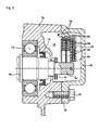
Fig. 2 is a cross-sectional view of essential parts showing the area in which the sliding contact brush assembly is located in the power transmission device of an electric vehicle in the first embodiment.. -
Fig. 3 is a perspective view of essential parts showing an assembled state of the sliding contact brush assembly with the protective jig being attached in the power transmission device for an electric vehicle in the first embodiment.. -
Fig. 4 is a perspective view of essential parts showing a final assembly state in which the location of the sliding contact brush assembly is covered in a power transmission device for an electric vehicle in the first embodiment. -
Fig. 5 is a perspective view showing a state in which protective cover is attached on the sliding contact brush assembly in the power transmission device for an electric vehicle in the first embodiment. -
Fig. 6 is a front view of a state in which sliding contact brush assembly is attached with a protective cover in the power transmission device for an electric vehicle in the first embodiment. -
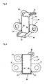
Fig. 7 is a perspective view of the protective cover in the power transmission device for an electric vehicle in the first embodiment. -
Fig. 8 is a plan view showing a protective cover in the power transmission device for an electric vehicle in the first embodiment. -
Fig. 9 is a cross-sectional view of protective cover along D-D inFig. 8 in a power transmission device for an electric vehicle. -
Fig. 10 is a diagram explaining an axial length in a final assembly state in which the location of the sliding contact brush assembly is covered by a brush case cover in the power transmission device for an electric vehicle in the first embodiment and explaining -
Fig. 11 is a diagram showing a relationship with respect to the axial length by which, through interposition of protective cover, the location of sliding contact brush assembly may not be covered by brush case cover in a power transmission device for an electric vehicle. -
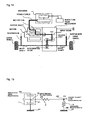
Fig. 12 is a schematic diagram showing a transmission path of high-frequency noise from a source of motor controlling inverter when no noise suppression is pursued in the power transmission device for an electric vehicle. -
Fig. 13 is a noise transmission circuit diagram showing a transmission circuit of high-frequency noise in a power transmission device for an electric vehicle. -
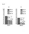
Fig. 14 denote comparative characteristics diagrams showing the comparison of noise level at preset locations of sliding contact brush in a power transmission device for an electric vehicle at the vehicle speed of 5km/h (a) and at the vehicle speed of 40 km/h (b). -
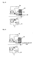
Fig. 15 shows an operative explanation diagram illustrating the assembly operation of the sliding contact brush assembly in a state in which a protective cover is attached in a power transmission device for an electric vehicle. -
Fig. 16 shows an operative explanation diagram illustrating the removal operation of the protective cover after the sliding contact brush assembly has been assembled in a power transmission device for an electric vehicle. -
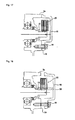
Fig. 17 shows an operative explanation diagram illustrating attaching operation of brush case caver in which the assembled sliding contact brush assembly is covered by the brush case cover in a power transmission device for an electric vehicle. -
Fig 18 shows an operative explanation diagram illustrating inability to mount a brush case cover when the brush cover has the protective cover attached. - In the following, description is made of the best mode realizing the power transmission device according to the present invention with reference to the first embodiment shown in the figures.
- First, the configuration will be described.
-
Fig. 1 is a schematic diagram showing an overall structure of a power transmission device for an electric vehicle (an example of power transmission device for an electrically driven vehicle). Overall structure or configuration is now described based onFig. 1 . - As shown in
Fig. 1 , the power transmission device in the first embodiment for an electric vehicle is provided with a motor 1, an inverter 2, reduction gear mechanism 3 (power transmission mechanism), a power transmission coupling unit 4, and a sliding contact brush earth structure 5. - The motor 1 is provided with a
motor housing 1 a, motor shaft 1 b rotatably mounted on themotor housing 1 a,rotors 1 c fixed to motor shaft 1 b, stator 1 e withmotor coils 1d wounded. As this motor 1, a synchronous motor of embedded magnets is used and therotor 1c has permanent magnet embedded therein. - The inverter 2 is connected to
motor coil 1 d of motor 1 via a three phase alternating current cable 6 while connected to a second battery 7 via a DC power cable 8. This inverter 2 has a function as a high-frequency controller for changing the direction of the current by the switching element. In a drive mode, DC current from the secondary battery 7 is converted to three-phase alternating current to the motor 1 while, at a regeneration, the three-phase AC from motor 1 will be converted to DC to the secondary battery 7. - The reduction gear mechanism 3 is interposed between motor shaft 1 b and drive wheels 9, 9, and is a power transmission mechanism having a case element, shaft element and power transmission element. A
gear case 3a accommodating the shaft element and power transmission element serves as the case element. As the shaft element, aninput shaft 3b,countershaft 3c, andoutput shafts first counter gear 3f, second counter gear 3g,drive gear 3h, and differential gear 31. - The power transmission coupling portion 4 is provided in a power transmission pathway from motor shaft 1 b to drive wheels 9, 9, and represents a resistance body imparting an electric resistance downstream of motor shaft 1 b. As this power transmission coupling 4, spline
fitting portion 4a,coupling portions 4b, 4c, gear meshing portion 4d, 4e, and the like may be used as being previously provided in the power transmission pathway of the reduction gear mechanism 3 for imparting electric resistance. The splinefitting portion 4a is a portion at which motor shaft 1 b andinput shaft 3b are connected via spline. Thecoupling portion output shafts shaft 3d', 3d' to drive wheels 9,9. The gear meshing portion 4d represents a meshing portion between input gear 3e andfirst counter gear 3f, and the gear meshing portion 4e is a meshing portion between second counter gear 3g and drivegear 3h. - The sliding contact brush ground structure 5 is a structure which connects electrically the position in the power transmission pathway at downstream of power transmission coupling portion 4 (spline
fitting portion 4a, gear meshing portion 4d) as a resistance body with avehicle body 10. This sliding contact brush ground structure 5 is provided withbrush contact spring gear case 3a, and connectingline 5b. Thebrush contact shaft end 3c' ofcountershaft 3c of reduction gear mechanism at the urging force ofspring lead brush contact gear case 3a. The connectingline 5b connects electricallygear case 3a andvehicle body 10. InFig. 1 ,11, 11 denote left and right suspensions, 12 denotes a breather hole. -
Figs. 2-4 show the setup portion of the slidingcontact brush assembly 25 in a power transmission device for an electric vehicle in the first embodiment. Hereinafter, on the basis ofFigs. 2-4 , the configuration of a setup portion of slidingcontact brush assembly 25 is described.. - As shown in
Fig. 2 , thecountershaft 3c is rotatably supported ongear case 3a viaball bearing 13, andfirst counter gear 3f (seeFig. 1 ) is fitted by spline on the inner position of thebal bearing 13. At the outside position ofball bearing 13 is provided anoil seal 14 ongear case 3a. Moreover, at the position ofshaft end 3c' (axis end) ofcountershaft 3c (shaft portion), which projects fromgear case 3a, astopper 15 and a pair ofbrush contacts contact brush assembly 25 in the electric power transmission pathway. - The
stopper 15 is provided, as shown inFigs. 2 and3 , onshaft end 3c' at the step position located on the rear side of the pair of contact position of thebrush contacts stopper 15 is of collar member intended, when mounting the brush case cover 16 to cover mountingportion 19, to prevent the protective cover 20 (brush protective jig) from being pushed in a attached state as shown inFig. 3 . - As shown in
Fig. 4 ,shaft end 3c 'of thecountershaft 3c is covered by thebrush case cover 16. As shown inFig. 3 , brush case cover 1 is mounted to cover mountingportion 19 enclosing theshaft end 3c' ofgear case 3a to open viabolt 18. By mounting and fixing thebrush case cover 16, as shown inFig. 2 , abrush chamber 17 is formed in communication withinterior chamber 3j ofgear case 3a. Further, brush case cover 16 is formed with abreather hole 12 disposed onbrush chamber 17, as shown inFig. 4 . - The pair of
brush contact shaft end 3c' ofcountershaft 3c. Thebrush contact brush holder 5c of insulating material withsprings springs 5d,5d. with maintaining contact withshaft end 3c' ofcountershaft 3c. - As shown in
Fig. 3 , thebrush holder 5c has acase fixing plate 21 which is fixed to acase extension 3a' extending fromgear case 3a viabolt 22. By fixation ofbrush holder 5c bybolt 22 to case, a pair ofbrush contacts shaft end 3c' of thecountershaft 3c. - Description of the configuration of the electrical connection of the pair of
brush contacts gear case 3a is now described. A pair ofbrush contacts spring seat spring spring seat Fig. 3 , to groundplate 23 provided withbrush holder 5c by soldering. Moreover,ground plate 23 is fixed to gearcase 3a viascrew 24. Through this configuration, a pair of contacts are connected electrically to gearcase 3a. -
Figs. 5 and 6 respectively show a state in which theprotective cover 20 is attached to the slidingcontact brush assembly 25 in a power transmission device for an electric vehicle in the first embodiment. The following describes the slide structure of theprotective cover 20 and the slidingcontact brush assembly 25. - As shown in
Figs. 5 and 6 , the slidingcontact brush assembly 25 is provided withbrush holder 5c, lead 5e, 5e,case fixing plate 21, andground plate 23, and is structured as a pre-assembled unit. Inside thebrush holder 5c, as described above,brush contact spring spring seat - As shown in
Figs. 5 and 6 , thebrush holder 5c comprises a pair ofgrooves brush contact - The
protective cover 20 has a pair ofslide pawls brush holder 5c when mounting to brushholder 5c. -
Figs. 7-9 show a configuration of aprotective cover 20 of the power transmission device for an electric vehicle in the first embodiment. The following describes the configuration of theprotective cover 20. - The
protective cover 20 is provided with amain cover portion 28 covering thebrush contact sub-cover portion sub-cover portion Fig. 8 , it is symmetrical with respect to an axial symmetry axis L1 as well as with respect to a symmetry axis L2 , a orthogonal direction relative to the axis. -
Figs. 10 and 11 show the axial dimensions of the setup portion of sliding contact brush in the power transmission device for an electric vehicle. Hereinafter, the setting of axial dimension of the protective cover 2 is described. - The
protective cover 20 is a protective jig that is mounted or attached over thebrush contacts brush assembly 25 to shaft end 3c '. The axial length L of theprotective cover 20 is set to the length in such a way that, when mounting the brush case cover 1 to cover mountingportion 19, the protective cover would interfere with the brush case cover 16 when mounted to the mountingportion 19 if remained in the mounted state. - That is, as shown in
Fig.10 , the internal clearance F is represented by the formula;: Internal clearance F = cover depth G + stopper depth H
Therefore, as shown inFig.11 , if, between the axial length L of protective cover 20 (=length of protective cover) and internal clearance F, the following relationship is established;,
length of protective cover L > internal clearance F
then, the length of protective cover represents a length by which interference with brush case cover 16 takes place when the protective cover remains attached during installation.
Further, sinceslide brush assembly 25 is accommodated inbrush chamber 17 without interference with slidingcontact brush assembly 25, when considering to include an axial length l of sliding contact brush assembly 25 (=length of brush), the following relationship is established. - The operation is now described.
First, a description of the "principle of generation of high-frequency noise and problems of comparative example". Subsequently, the operation in the power transmission for an electrically driven vehicle of the first embodiment is described separately in the order of "operation of high-frequency noise reduction", "operation of sliding contact brush setup to the reduction gear mechanism", "comparison of noise reduction operation depending on the ground position", "preventive operation to forget removal of protective cover". - Like a hybrid vehicle or an electric vehicle, in an electrically driven vehicle in which an electric motor is provided as part of driving power for travel, it is known that the high-frequency noise emitted from an inverter for controlling the motor can adversely affect the radio receiver or the like due radiation to the outside as motor drive system as antenna.
- The principle of generation of high frequency noise will be described with reference to
Fig. 12 .
In the phase control of an inverter to change the direction of the current through the switching element, since there is a steep rise in waveform of the current (voltage) when turned on, high-frequency clicking noise (= high-frequency noise) occurs. As indicated by the bold arrows inFig. 12 , high-frequency noise generated by the inverter is transmitted to the motor shaft via a power cable and motor coil. It is further propagated from the motor shaft via input gear of reduction unit, countershaft, differential gear, ad drive shaft to the suspension, which is insulated by the drive wheels. The propagation or transmission path as indicated by bold arrows inFig 12 acts as an antenna to emit the high-frequency noise to the outside, thereby causing electromagnetic interference. - By comparison, as described in the prior art described above, a comparative example is set in which the electrical contact position of sliding contact brush is located at motor shaft and earthing is made or grounded to the vehicle body at the position of the electrical connection of the motor shaft .
- First, in order to reduce high-frequency noise from the inverter, it is necessary to reduce the output voltage V2 going out to the drive shaft from the motor (see
Fig. 13 ).
Here, output voltage V2 may be expressed by the equation;
Here, V1: motor side voltage, Z8: earth resistance, ZR: upstream resistance, respectively. - As is apparent from equation (1) above, to reduce the output voltage V2, along with the reduction in the ground resistance ZB due to sliding contact brush and the like, at the upstream side of electrical contact position for earthing, i.e., the upstream resistance ZR on the noise generation side has to be increased.
- In contrast, in the comparative example described above, although the motor shaft may be grounded to the vehicle body, the position of grounding is at motor shaft. Thus, the inverter, i.e., source of noise generation, is close, the distance between the source of noise generation (inverter) and the position of electrical contact for earthing (motor shaft) is short, and the upstream resistance ZR will be smaller. Therefore, reduction of output voltage V2 is of small margin, noise propagation occurs downstream in the drive shaft direction.
- As described above, in the power transmission device for an electric vehicle equipped with an inverter 2 as a source of noise, it is important to secure the large upstream resistance ZR to reduce high-frequency noise emitted to the outside. The following describes the reduction effect of high-frequency noise in a first embodiment reflecting this.
- In a power transmission device for an electric vehicle in the first embodiment, a power transmission coupling portion 4 is provided in a power transmission path extending from the motor shaft 1 b to the drive wheels 9,9. In addition, the sliding contact brush ground structure 5 is electrically connected to
vehicle body 10. Further, the positional relationship between power transmission coupling portion 4 and sliding contact brush ground structure 5 is such that the power transmission coupling portion 4 (resistance body) is provided downstream of motor shaft 1 b, and the position further downstream of the power transmission coupling portion 4 is set as the electrical connection position CP of sliding contact brush ground structure 5. - Therefore, since the electrical connection position CP of sliding contact brush ground structure 5 is located downstream of the motor shaft 1 b and power transmission coupling portion 4, compared with the comparative example in which motor shaft is selected as electrical connection position, such a positional relationship is obtained remote from the inverter, i.e., source of noise generation. In addition, due to power transmission connection portion 4, electric resistance (upstream side resistance ZR) Is provided at upstream position from the electrical connection position CP of the sliding contact brush ground structure 5.
- Therefore, the upstream side resistance ZR representing the upstream resistance of the electrical connection position CP of sliding contact brush ground structure 5 becomes larger, and as apparent from equation (1) described above, the output voltage V2 can be reduced. Therefore, the output voltage, V2 exiting downstream from the electrical connection position CP of sliding contact brush ground structure 5 is attenuated, and the noise propagated from upstream to downstream in the power transmission path is reduced.
- Thus, by reducing the noise propagation from inverter 2 via motor 1 towards the power transmission path,
a noise emission function in which a high-frequency noise will be radiated to outside by an antenna formed byoutput shaft - As described above, in the power transmission device of an electric vehicle in the first embodiment, at downstream position from motor shaft 1 b, a power transmission coupling portion 4 is provided, and at the position further downstream of the power transmission coupling portion, an electrical connection position CP of sliding contact brush ground structure 5 is configured to be set. Consequently, it is possible, in an electric vehicle equipped with an inverter 2 as a source of noise, to reduce high-frequency noise emitted to the outside.
- In the first embodiment, the electrical coupling position P of the sliding contact brush structure 5 is set by
brush contact shaft end 3c' of countershaft 3. Therefore, it is necessary to ensure thatbrush contact - In the sliding contact brush ground structure 5 in the first embodiment,
brush contact shaft end 3c' ofcountershaft 3c separated by seal byoil seal 14 from the first counter gear 3e.
In other words, the setup position ofbrush contact gear chamber 3j of gear reduction mechanism 3.
Thus, by separating from lubricating oil of gear reduction mechanism 3, a stable contact resistance due tobrush contact brush contact gear chamber 3j of gear reduction mechanism 3. - In the first embodiment, the position of
brush contact shaft end 3c' projecting fromgear case 3a of gear reduction mechanism 3. In addition,shaft end 3c' is covered, brush case cover 16 formingbrush chamber 17 in communication withgear chamber 3j of reduction gear mechanism 3 is fixed to gearcase 3a, and breather hold 12 is provided in the brush case cover 16 to be disposed onbrush chamber 17.
That is, both thegear chamber 3j ofreduction gear mechanism 3j andbrush chamber 17 setting up thebrush contact breather hole 12, so that the difference between thegear chamber 3j andbrush chamber 17 is suppressed to generate.
Therefore, when the internal pressure of thereduction gear mechanism 3j is increased, lubricating oil in thegear chamber 3j may be prevented from leaking tobrush chamber 17 throughoil seal 14. - The power transmission mechanism in the first embodiment is a reduction gear mechanism 3 having an
input shaft 3b,countershaft 3c,output shaft gear train 3e,3f, andgear train 3g, 3h where the electrical coupling position CP of sliding contact brush ground structure is set at the position ofshaft end 3c' ofcountershaft 3c.
That is, splinefitting portion 4a and gear meshing portion 4d are provided upstream of the electrical coupling position CP of sliding contact brush ground structure 5, and the upstream side resistance ZR is secured by these two power transmission coupling portion 4.
Therefore, by ensuring large upstream side resistance ZR, out of noise propagation directing from upstream to downstream in the power transmission path, the noise propagation towards theoutput shaft countershaft 3c may be effectively reduced. - When comparing the first embodiment and comparative example, in view of difference in the electrical coupling position CP for grounding or earthing, it is necessary to verify the effectiveness of variation in that position. The following describes the comparison of reduction operation of high-frequency noise depending on the ground position in the first embodiment reflecting this.
- First, in the case of the comparative example of positioning the A portion in
Fig. 1 (opposite from the reduction gear mechanism 3) as ground position, as shown inFig. 14 (a), (b) , high noise level is noticed at both travel speed of 5 km/h and 40 km/h. In particular, during high speed travel, it is likely that the high-frequency noise poses a problem. - By comparison, in the modification example in the first embodiment that positions the B position in
Fig. 1 (shaft end of input shaft) as ground position, as shown in Fig.(a), (b), at both vehicle speed of 5km/h and 40km/h, noise level is lower as compared to the comparative example(Fig. 1A portion). - In the case the first embodiment in which the position C in
Fig. 1 (shaft end of countershaft) is positioned as ground position, as shown inFig. 14(a), (b) , at both travel speeds of 5km/r and 40km/h, noise level is lower than the comparative example(Fig. 1 A) . - In other words, when observing the result of the comparison in
Fig. 14 (a), (b), compared to the noise level in the motor shaft end setup example (Fig. 1A position), the noise level in the input shaft end setup example (Figure 1 B position) is lower. Further, the noise level in countershaft end setup example (Fig. 1 C ) is lower than that in the input shaft end setup example (Fig. 1 B position).
Based on the comparison results, by setting theshaft end 3c' ofcountershaft 3c as ground position, it has been confirmed the reduction in high-frequency noise emitted to the outside. - By looking closer the comparison results, as shown in Fig. 14(d), it has been confirmed that, compared with the noise level in the motor shaft end setup example (
Fig.1A position), the noise level at 5 km/h travel is reduced by Δα dB.
The noise level in the countershaft end setup example (Fig.1C position) in the first embodiment at 5 km/h travel speed is reduced by Δα' dB ( < Δα dB). - As shown in
Fig. 14(b) , compared to the noise level in the motor shaft end setup example (Fig. 1A position), the noise level in the input shaft end setup example (Fig.1 B position) at 40 km/h travel speed, the noise level is reduced by Δβ dB. The noise level in countershaft end setup example in the first embodiment(Fig.1C ) at 40km / h travel speed is reduced by Δβ dB ( < Δβ' dB).
This comparison result confirms that, especially in the first embodiment, during high travel speed, the reduction effect of high-frequency noise emitted to the outside will be effectively reduced. - First of all, on the basis of
Fig.15 through Fig. 17 , the assembly operation of slidingcontact brush assembly 25 and brush case cover 16 is described. - By inserting a pair of
slide pawls protective cover 20 in sliding relationship with 26,26 with respect to a pair ofslide groove brush holder 5c, the slidingcontact brush assembly 25 is fitted toprotective cover 20. Further, slidingcontact brush assembly 25 fitted withprotective cover 20 is positioned, as shown inFig. 15 , at the position ofshaft end 3c' ofcountershaft 3c. By screwing to tightenbolt contact brush assembly 25 is fastened to gearcase 3a. In addition, by screwing to tightenground screw 24, slidingcontact brush assembly 25 is grounded to earth to gearcase 3a. - As described above, after completion of mounting the sliding
contact brush assembly 25 to case and grounding of slidingcontact assembly 25, the protective cover fitted or attached to the slidingcontact brush assembly 25 will be removed by sliding in the direction of the arrow inFig. 16 . Through these operations, installation or assembly of the slidingcontact brush assembly 25 will be complete.
Further, with respect to thecover mounting portion 19 ofgear case 3a, from which theprotective cover 20 has been removed, as shown inFig. 17 , as shown inFig. 17 , after aligning the mounting position ofbrush case cover 16, byscrew tightening bolt 18, the installation or assembly operation of brush case cover 16 is complete. - Thus, when assembling the sliding
contact brush assembly 25 to shaft end 3c' ofcountershaft 3c,protective cover 20 is attached overbrush contact contact brush assembly 25. Further, when mounting brush case cover 16 to cover mountingportion 19, if theprotective cover 20 remains to be attached, then as shown inFig. 18 ,protective cover 20 interferes withbrush case cover 16. Therefore, unless theprotective cover 20 is removed, installation or mounting to thecover mounting portion 19 of brush case cover 16 is not possible so thatprotective cover 20 is prevented from being forgotten to be removed. - Also, the
protective cover 20 is configured to have an axial length L by which, when mounting brush case cover 16 to cover mountingportion 19, the protective cover would interfere withbrush case cover 16. In other words, the axial length ofprotective cover 20 will be longer than the axial length l of the slidingcontact brush assembly 25. Therefore, at the fitting operation to brushholder 5c, theprotective cover 20 may be easily grasped by hand, which makes the fitting and removal ofprotective cover 20 easier with improved workability. - As a result, it is possible to prevent from forgetting the removal of the
protection cover 20 during the work of assembling the slidingcontact brush assembly 25, while improving workability, theprotective cover 20 for protectingbrush contact - In the first embodiment, a configuration was adopted in which
protective cover 20 is not pushed bybrush case cover 18.
With this configuration, when an attempt is made to mount brush case cover 16 withprotection cover 20 remain being attached, by hitting on thestopper 15, protective cover would not be pushed into rearward from the abutment position to thestopper 15, so that brush case cover 16 will be prevented to be mounted.
Therefore, when mountingbrush case cover 16, if theprotective cover 20 remains attached, brush case cover 16 is prevented from being pushed in, the removal ofprotective cover 20 is prevented from being forgotten. - In the first embodiment, a structure is adopted in which a pair of
slide grooves brush holder 5c, while a pair ofslide pawls protective cover 20.
With this configuration, since theprotective cover 20 is slid in the direction of the groove, working operation of mounting and removing of theprotective cover 20 is facilitated. Also, if an attempt is made to mount brush case cover 16 whileprotective cover 20 is being attached, by guiding by slide theprotective cover 20, a reliably abutment onstopper 15 is ensured withoutprotective cover 20 being placed oblique.
Therefore, sliding guide will not only to enhance workability to make removing and mounting operations ofprotective cover 20 easier. In addition, removal ofprotective cover 20 may be reliably prevented from being forgotten. - In the first embodiment, the
protective cover 20 is configured of symmetrical structure.
This configuration allows, when mountingprotective cover 20 to brushholder 5c, regardless of the orientation of theprotective cover 20, mounting is possible on either orientation.
Therefore, when mountingprotective cover 20 to brushholder 5c, workability is not only improved by the attachment ofprotective cover 20 without considering the orientation ofprotective cover 20, but along with improvement in workability, risk of damage of tip ofprotective cover 20 and adhesion of foreign objects and the like will be reduced. - Next, a description of effect will be given.
In the power transmission device for an electric vehicle of the first embodiment, the effects listed below are obtained. - (1) Provided are a power transmission mechanism (reduction gear mechanism 3) interposed between a motor shaft 1 b of motor 1 driven by an inverter 2 and drive wheels 9,9 and having
a case element (gear case 3a), axis element (countershaft 3c and the like) and power transmission element (first counter gear 3f and the like), a sliding contact brush (sliding contact brush assembly 25) mounted on the axis end (shaft end 3c') of the axis element (countershaft 3c) with one end contacted to the axis end (shaft end 3c') while with the other end electrically grounded to avehicle body 10,
a brush case cover 16 mounted to acover mounting portion 19 that encloses the axis end (shaft end 3c') of axis element (countershaft 3c) in the case element (gear case 3a) and opens, and forming abrush chamber 17 accommodating the sliding contact brush (sliding contact brush assembly 25),
and a brush protective jig (protective cover) fitted or attached onbrush contact shaft end 3c') and is configured to have an axial length L by which to contact the brush case cover 16 when mounting the brush case cover 16 to thecover mounting portion 19 in the attached state of the protective jig (Fig. 3 ).
For this reason, when assembling the sliding contact brush (sliding contact brush assembly 25), while workability is improved, the brush protective jig (protective cover 20) protectingbrush contact - (2) The axis end (
shaft end 3c') of the axis element (countershaft 3c) is provided with astopper 15 at the rearward position from the abutment position of thebrush contact Fig.3 ).
Thus, in addition to the effect (1) described above, at mounting ofbrush case cover 16, by preventing brush case cover 16 from being pushed in a state in which the brush protective jig (protective cover 20) remains in the attached state so that the removal ofprotective cover 20 may securely be prevented from being forgotten. - (3) The
brush contact brush holder 5c that is disposed, when fixed to the case element (gear case 3a), with maintaining contact to the axis end (shaft end 3') of the shaft element (countershaft 3c), and thebrush holder 5c is provided with a pair ofparallel slide grooves brush contact parallel slide pawls parallel slide grooves brush holder 5c, when mounted to thebrush holder 5c (Fig.6 ).
Thus, in addition to the effects (1) or (2), mounting and removal operation of the brush protective jig (protective cover 20) will be easy by the slidably guide to achieve the improvement in workability In addition, the removal of brush protective jig (protective cover 20) will be prevented from being forgotten reliably. - (4) The brush protective jig is configured to be a
protective cover 20 provided with amain cover portion 28 to cover thebrush contact sub-cover portions main cover portion 28, and a pair ofparallel slide pawls sub-cover portions protective cover 20 is configured to have a left-right symmetrical structure having a axial symmetry axis L1 and a lateral symmetry axis L2 perpendicular to the axis (Fig. 8 ).
Thus, in addition to the effect (3) described above, when mounting theprotective cover 20 to brushholder 5c, mounting operation without care about the orientation of theprotective cover 20 allows not only improvement in workability, but also reduce the risk of the tip or distal end of the protective cover being damaged or adhesion of foreign matters or the like along with the improvement in workability. - Although the power transmission device for an electric vehicle according to the present invention above has been described with reference to the first embodiment, the concrete structure is not limited to this first embodiment, but unless the essence or sprit of the present invention related to each claim is not departed, design change and addition are allowed.
- In the first embodiment, as a power transmission mechanism, an example of the reduction gear mechanism 3 by two-step-reduction is shown. However, for example, such as one step reduction, three-step-reduction and the like, a gear reduction mechanism of other than the two-step-reduction may be employed. Alternatively, a gear change mechanism using a planetary gear may be also employed. In addition, a belt type continuous transmission or troidal type continuous transmission may be examples. In short, as long as the power transmission device includes a case element, axis element and power transmission element, such power transmission mechanism is to be included in the present invention.
- In the first embodiment, the brush protective jig is configured in
protective cover 20 provided with amain cover portion 28, asub-cover portion pawls protective cover 20 as brush protective jig may be mounted or attached when assembling the slidingcontact brush assembly 25 to shaft end 3c', or may be intended to be attached to the slidingcontact brush assembly 25 in advance. - In the first embodiment, an example is shown as applied to an electric vehicle, application to a hybrid vehicle, fuel cell vehicle and the like is possible. In short, the invention may be applicable to an electrically driven vehicle with an inverter and motor as source of noise generation.
- The present invention claims priority based on a Japanese Patent Application,
2010-257838 - The purpose of the present invention is to ensure reduction performance of radio noise while improving a workability and preventing a brush protective jig for protecting a brush contact from being forgotten to be removed, when assembling a slide contact brush. A power transmission device for an electrically driven vehicle includes: a reduction gear mechanism (3); a slide contact brush assembly (25); a brush case cover (16); and a protective cover (20). The reduction gear mechanism (3) is interposed between a motor (1) driven by an inverter (2) and drive wheels (9,9). The slide contact brush assembly (25) is provided at the position of a shaft end (3c') of a countershaft (3c). The brush case cover (16) is mounted to a cover mounting portion (19). The protective cover (20) is mounted so as to cover brush contacts (5a, 5a) when the slide contact brush assembly (25) is assembled to the shaft end (3c'). The protective cover (20) is set to have the axial length (L) interfering with the brush case cover (16), when the brush case cover (16) is mounted to the cover mounting portion (19) in a state where the protective cover (20) is installed.
Claims (5)
- A power transmission device for an electrically driven vehicle, comprising:a power transmission mechanism interposed between a motor shaft of a motor driven by an inverter and drive wheels, and having a case element, an axis element and a power transmission element,a sliding contact brush mounted on the axis end of the axis element with one end contacted to the axis end while with the other end electrically grounded to a vehicle body,a brush case cover mounted to a cover mounting portion that encloses the axis end of the axis element in the case element and opens, and forming a brush chamber accommodating the sliding contact brush, anda brush protective jig mounted to cover a brush contact when mounting the sliding contact brush to the axis end and is configured to have an axial length by which to contact the brush case cover when mounting the brush case cover to the cover mounting portion in the attached state of the brush protective jig..
- The power transmission device for an electric vehicle claimed in claim 1,wherein
the axis end of the axis element is provided with a stopper at the rearward position from the
abutment position of the brush contact, the stopper preventing the brush protective jig from being pushed in
an attached state of the brush protective jig when mounting the brush case cover to the cover mounting portion. - The power transmission device for an electrically driven vehicle claimed in either claim 1 or 2, wherein
the brush contact is provided in brush holder that is disposed, when fixed to the case element, with maintaining contact to the axis end of the axis element, and the brush holder is provided with a pair of parallel slide grooves extending axially from both side surfaces sandwiching the end face from which brush contact projects, and
the brush protective jig is provided with a pair of parallel slide pawls to be engaged with the parallel slide grooves provided with the brush holder, when mounted to the brush holder - The power transmission device for an electrically driven vehicle claimed in claim 3, wherein
the brush protective jig is configured to be a protective cover provided with a main cover portion to cover the brush contact, a pair of sub-cover portions extending from both sides of the main cover portion, and the pair of parallel slide pawls formed in the end portion of the pair of sub-cover portions, wherein the protective cover is configured to have a left-right symmetrical structure having a axial symmetry axis and a lateral symmetry axis perpendicular to the axis. - A manufacturing method of a power transmission device for an electrically driven vehicle having
a power transmission mechanism interposed between a motor shaft of a motor driven by an inverter and drive wheels, and having a case element, an axis element and a power transmission element, comprising:mounting step for mounting a sliding contact brush on the axis end of the axis element with one end being contacted to the axis end while with the other end electrically grounded to a vehicle body,removing step for removing the brush protective jig covering a brush contact when mounting the sliding contact brush to the axis end, and the axial length of which is set in such a way that, when mounting the brush case cover to the cover mounting portion, the brush protective jig would interfere with the brush case cover; andmounting step for mounting the brush case cover to the cover mounting portion that encloses the axis end of the axis element in the case element and opens, and forming a brush chamber accommodating the sliding contact brush.
Applications Claiming Priority (2)
| Application Number | Priority Date | Filing Date | Title |
|---|---|---|---|
| JP2010257838A JP5573622B2 (en) | 2010-11-18 | 2010-11-18 | Power transmission device for electric vehicle and method for producing power transmission device for electric vehicle |
| PCT/JP2011/072603 WO2012066857A1 (en) | 2010-11-18 | 2011-09-30 | Power transmission device for electric vehicle and production method therefor |
Publications (3)
| Publication Number | Publication Date |
|---|---|
| EP2642163A1 true EP2642163A1 (en) | 2013-09-25 |
| EP2642163A4 EP2642163A4 (en) | 2018-03-28 |
| EP2642163B1 EP2642163B1 (en) | 2019-07-24 |
Family
ID=46083800
Family Applications (1)
| Application Number | Title | Priority Date | Filing Date |
|---|---|---|---|
| EP11840976.2A Active EP2642163B1 (en) | 2010-11-18 | 2011-09-30 | Power transmission device for electric vehicle and production method therefor |
Country Status (5)
| Country | Link |
|---|---|
| US (1) | US9154021B2 (en) |
| EP (1) | EP2642163B1 (en) |
| JP (1) | JP5573622B2 (en) |
| CN (1) | CN103221719B (en) |
| WO (1) | WO2012066857A1 (en) |
Cited By (1)
| Publication number | Priority date | Publication date | Assignee | Title |
|---|---|---|---|---|
| FR3078841A1 (en) * | 2018-03-08 | 2019-09-13 | Valeo Equipements Electriques Moteur | ROTATING ELECTRIC MACHINE HAVING A BROOM HOLDER MOUNTED ON THE CARTER |
Families Citing this family (19)
| Publication number | Priority date | Publication date | Assignee | Title |
|---|---|---|---|---|
| JP6021669B2 (en) * | 2013-02-04 | 2016-11-09 | 株式会社ディスコ | Cutting equipment |
| JP6151536B2 (en) * | 2013-03-08 | 2017-06-21 | 本田技研工業株式会社 | Power transmission device |
| JP6308792B2 (en) * | 2014-02-06 | 2018-04-11 | 愛知機械工業株式会社 | Power transmission mechanism |
| CN204153985U (en) * | 2014-09-19 | 2015-02-11 | 芜湖美的厨卫电器制造有限公司 | There is the electric heater of blowoff valve |
| EP3279515B1 (en) * | 2015-03-31 | 2022-05-04 | Aichi Machine Industry Co., Ltd. | Power transmission device and power output apparatus provided with same |
| DE102016200766A1 (en) * | 2016-01-21 | 2017-07-27 | Bayerische Motoren Werke Aktiengesellschaft | Electric machine |
| JP6607984B2 (en) * | 2018-03-05 | 2019-11-20 | 本田技研工業株式会社 | Power equipment |
| CN108688471A (en) * | 2018-04-13 | 2018-10-23 | 无锡市东鹏金属制品有限公司 | High ferro dynamical system is grounded reflux |
| DE102018206107A1 (en) * | 2018-04-20 | 2019-10-24 | Zf Friedrichshafen Ag | Grounding of a generator |
| DE102018218530A1 (en) * | 2018-10-30 | 2020-04-30 | Zf Friedrichshafen Ag | Brush device for the electrical connection of a first element to a second element, electric machine and drive device |
| DE102018219779A1 (en) * | 2018-11-19 | 2020-05-20 | Zf Friedrichshafen Ag | Sealing device, electric machine and drive device |
| CN111665439B (en) * | 2019-03-05 | 2022-11-22 | 日本电产增成机器装置(浙江)有限公司 | Component for motor test |
| FR3098360B1 (en) * | 2019-07-04 | 2021-06-04 | Renault Sas | DEVICE FOR FIXING AN ANTI-PARASITE BROOM ON A CRANKCASE AND SPEED REDUCER |
| DE102020203162A1 (en) | 2020-03-12 | 2021-09-16 | Zf Friedrichshafen Ag | Arrangement for the electrical grounding of a rotor of an electrical machine with respect to a housing |
| CN113364222B (en) * | 2021-05-17 | 2024-04-16 | 联合汽车电子有限公司 | Grounding device, motor and vehicle |
| EP4661258A4 (en) | 2023-02-01 | 2026-05-06 | Jatco Ltd | UNIT |
| JPWO2024161716A1 (en) | 2023-02-01 | 2024-08-08 | ||
| DE102023118891A1 (en) * | 2023-07-18 | 2025-01-23 | Schaeffler Technologies AG & Co. KG | Electrical contacting device, method for assembling the electrical contacting device, method for assembling a component and establishing an electrical contact between the component and the electrical contacting device and electrical drive device |
| WO2025225254A1 (en) * | 2024-04-25 | 2025-10-30 | トライス株式会社 | Earth brush unit |
Family Cites Families (16)
| Publication number | Priority date | Publication date | Assignee | Title |
|---|---|---|---|---|
| US3267312A (en) * | 1961-09-21 | 1966-08-16 | Gen Motors Corp | Dynamoelectric machine terminal connection |
| US3242362A (en) * | 1963-05-16 | 1966-03-22 | Ford Motor Co | Dynamoelectric machine brush holder assembly |
| JPS6336156A (en) | 1986-07-30 | 1988-02-16 | Toshiba Corp | Electric field measuring instrument for high voltage equipment |
| JPS6336156U (en) * | 1986-08-27 | 1988-03-08 | ||
| US5495134A (en) * | 1993-09-20 | 1996-02-27 | Itt Automotive Electrical Systems Inc. | Dynamoelectric brush holder |
| JP3654312B2 (en) * | 1995-10-19 | 2005-06-02 | 株式会社デンソー | Method of assembling brush assembly of rotating electric machine and brush support jig used at the time |
| JP2000244180A (en) * | 1999-02-22 | 2000-09-08 | Toyota Motor Corp | Electromagnetic noise suppression device for electric vehicles |
| JP2000310296A (en) * | 1999-04-23 | 2000-11-07 | Aisin Aw Co Ltd | Drive for electric vehicles |
| JP3620442B2 (en) * | 2000-12-04 | 2005-02-16 | 株式会社日立製作所 | Vehicle drive assist device |
| JP3661655B2 (en) * | 2002-02-27 | 2005-06-15 | 株式会社デンソー | Brush support jig used for assembly of brush assembly of rotating electric machine and assembly method of brush assembly using the same |
| GB0328386D0 (en) * | 2003-12-06 | 2004-01-14 | Johnson Electric Sa | Brush holder assembly for an electric motor |
| JP2006320129A (en) * | 2005-05-13 | 2006-11-24 | Nissan Motor Co Ltd | Vehicle motor drive device |
| JP2007288840A (en) * | 2006-04-12 | 2007-11-01 | Toyota Motor Corp | Motor with brush |
| JP4860423B2 (en) * | 2006-10-16 | 2012-01-25 | 株式会社ミツバ | Electric motor with reduction mechanism |
| JP2009029326A (en) * | 2007-07-30 | 2009-02-12 | Toyota Motor Corp | vehicle |
| DE102007059555A1 (en) * | 2007-12-11 | 2009-06-18 | Hoffmann & Co. Elektrokohle Ag | Brush assembly for an electric machine, spring and seal assembly for the same, and method of making the same |
-
2010
- 2010-11-18 JP JP2010257838A patent/JP5573622B2/en active Active
-
2011
- 2011-09-30 CN CN201180055834.7A patent/CN103221719B/en active Active
- 2011-09-30 WO PCT/JP2011/072603 patent/WO2012066857A1/en not_active Ceased
- 2011-09-30 EP EP11840976.2A patent/EP2642163B1/en active Active
- 2011-09-30 US US13/988,186 patent/US9154021B2/en active Active
Non-Patent Citations (1)
| Title |
|---|
| See references of WO2012066857A1 * |
Cited By (1)
| Publication number | Priority date | Publication date | Assignee | Title |
|---|---|---|---|---|
| FR3078841A1 (en) * | 2018-03-08 | 2019-09-13 | Valeo Equipements Electriques Moteur | ROTATING ELECTRIC MACHINE HAVING A BROOM HOLDER MOUNTED ON THE CARTER |
Also Published As
| Publication number | Publication date |
|---|---|
| JP5573622B2 (en) | 2014-08-20 |
| EP2642163A4 (en) | 2018-03-28 |
| CN103221719A (en) | 2013-07-24 |
| WO2012066857A1 (en) | 2012-05-24 |
| EP2642163B1 (en) | 2019-07-24 |
| CN103221719B (en) | 2015-11-25 |
| US9154021B2 (en) | 2015-10-06 |
| JP2012110149A (en) | 2012-06-07 |
| US20130241342A1 (en) | 2013-09-19 |
Similar Documents
| Publication | Publication Date | Title |
|---|---|---|
| EP2642163B1 (en) | Power transmission device for electric vehicle and production method therefor | |
| KR20150038694A (en) | Power transmission device for electric vehicle | |
| JP4015120B2 (en) | Power cable holding structure for vehicle and method for assembling power cable assembly for vehicle | |
| EP3789273A1 (en) | Vehicle front structure and vehicle | |
| US8939795B2 (en) | Shield structure of conductor cable and electrically driven vehicle | |
| US20200070756A1 (en) | Electrical device | |
| US9425561B2 (en) | High voltage electrical connector | |
| CN109911028B (en) | Oil pan guards for vehicles | |
| CN110861598A (en) | Electrical installation structure in vehicle | |
| EP2566014B1 (en) | Motor with decelerator and sunroof drive device | |
| CN114270667A (en) | Electric drives and drive assemblies | |
| KR20120097780A (en) | A shielded connector | |
| US8937401B2 (en) | Vehicle with drive system providing reduced emissions | |
| JP6172310B2 (en) | Power transmission device for electric vehicle | |
| EP2557611A1 (en) | High voltage secondary battery with earth member | |
| CN111717133B (en) | Vehicle-mounted device | |
| JP5877463B2 (en) | Shield shell | |
| EP4525573B1 (en) | Systems for molding metal sheet into inverter for improving emc performance | |
| US12604430B2 (en) | Systems for integrating choke into inverter header sub-assembly for improving EMC performance | |
| EP3713054A1 (en) | Motor for vehicle | |
| JP2025122549A (en) | Electric vehicle drive unit | |
| CN118514521A (en) | Electric Vehicles | |
| CN118826573A (en) | Drive unit | |
| JP2013193692A (en) | High voltage apparatus |
Legal Events
| Date | Code | Title | Description |
|---|---|---|---|
| PUAI | Public reference made under article 153(3) epc to a published international application that has entered the european phase |
Free format text: ORIGINAL CODE: 0009012 |
|
| 17P | Request for examination filed |
Effective date: 20130517 |
|
| AK | Designated contracting states |
Kind code of ref document: A1 Designated state(s): AL AT BE BG CH CY CZ DE DK EE ES FI FR GB GR HR HU IE IS IT LI LT LU LV MC MK MT NL NO PL PT RO RS SE SI SK SM TR |
|
| DAX | Request for extension of the european patent (deleted) | ||
| RA4 | Supplementary search report drawn up and despatched (corrected) |
Effective date: 20180228 |
|
| RIC1 | Information provided on ipc code assigned before grant |
Ipc: H01R 39/38 20060101ALI20180222BHEP Ipc: H02K 11/40 20160101ALI20180222BHEP Ipc: B60L 7/14 20060101ALI20180222BHEP Ipc: F16H 57/02 20120101AFI20180222BHEP Ipc: H02K 15/00 20060101ALI20180222BHEP Ipc: H02K 13/00 20060101ALI20180222BHEP Ipc: H02K 7/116 20060101ALI20180222BHEP Ipc: B60L 11/18 20060101ALI20180222BHEP |
|
| STAA | Information on the status of an ep patent application or granted ep patent |
Free format text: STATUS: EXAMINATION IS IN PROGRESS |
|
| 17Q | First examination report despatched |
Effective date: 20181113 |
|
| RIC1 | Information provided on ipc code assigned before grant |
Ipc: H02K 13/00 20060101ALI20180222BHEP Ipc: B60L 7/14 20060101ALI20180222BHEP Ipc: H02K 15/00 20060101ALI20180222BHEP Ipc: H01R 39/38 20060101ALI20180222BHEP Ipc: H02K 7/116 20060101ALI20180222BHEP Ipc: B60L 11/18 20060101ALI20180222BHEP Ipc: H02K 11/40 20160101ALI20180222BHEP Ipc: F16H 57/02 20120101AFI20180222BHEP |
|
| GRAP | Despatch of communication of intention to grant a patent |
Free format text: ORIGINAL CODE: EPIDOSNIGR1 |
|
| STAA | Information on the status of an ep patent application or granted ep patent |
Free format text: STATUS: GRANT OF PATENT IS INTENDED |
|
| RIC1 | Information provided on ipc code assigned before grant |
Ipc: B60L 7/14 20060101ALI20190315BHEP Ipc: H02K 11/40 20160101ALI20190315BHEP Ipc: H02K 15/00 20060101ALI20190315BHEP Ipc: H01R 39/38 20060101ALI20190315BHEP Ipc: H01R 43/12 20060101ALI20190315BHEP Ipc: H02K 5/14 20060101ALI20190315BHEP Ipc: H02K 5/15 20060101ALI20190315BHEP Ipc: H02K 13/00 20060101ALI20190315BHEP Ipc: H02K 7/116 20060101ALI20190315BHEP Ipc: B60L 50/51 20190101ALI20190315BHEP Ipc: F16H 57/02 20120101AFI20190315BHEP |
|
| INTG | Intention to grant announced |
Effective date: 20190405 |
|
| RIN1 | Information on inventor provided before grant (corrected) |
Inventor name: KARIYA, TAKESHI Inventor name: MORIKURA, KIYOSHI Inventor name: HOSHIKA, SEIJI Inventor name: SOEDA, KAZUHIKO |
|
| GRAS | Grant fee paid |
Free format text: ORIGINAL CODE: EPIDOSNIGR3 |
|
| GRAJ | Information related to disapproval of communication of intention to grant by the applicant or resumption of examination proceedings by the epo deleted |
Free format text: ORIGINAL CODE: EPIDOSDIGR1 |
|
| GRAL | Information related to payment of fee for publishing/printing deleted |
Free format text: ORIGINAL CODE: EPIDOSDIGR3 |
|
| STAA | Information on the status of an ep patent application or granted ep patent |
Free format text: STATUS: EXAMINATION IS IN PROGRESS |
|
| GRAR | Information related to intention to grant a patent recorded |
Free format text: ORIGINAL CODE: EPIDOSNIGR71 |
|
| STAA | Information on the status of an ep patent application or granted ep patent |
Free format text: STATUS: GRANT OF PATENT IS INTENDED |
|
| GRAA | (expected) grant |
Free format text: ORIGINAL CODE: 0009210 |
|
| STAA | Information on the status of an ep patent application or granted ep patent |
Free format text: STATUS: THE PATENT HAS BEEN GRANTED |
|
| INTC | Intention to grant announced (deleted) | ||
| AK | Designated contracting states |
Kind code of ref document: B1 Designated state(s): AL AT BE BG CH CY CZ DE DK EE ES FI FR GB GR HR HU IE IS IT LI LT LU LV MC MK MT NL NO PL PT RO RS SE SI SK SM TR |
|
| INTG | Intention to grant announced |
Effective date: 20190617 |
|
| REG | Reference to a national code |
Ref country code: GB Ref legal event code: FG4D |
|
| REG | Reference to a national code |
Ref country code: CH Ref legal event code: EP |
|
| REG | Reference to a national code |
Ref country code: DE Ref legal event code: R096 Ref document number: 602011060782 Country of ref document: DE |
|
| REG | Reference to a national code |
Ref country code: AT Ref legal event code: REF Ref document number: 1158578 Country of ref document: AT Kind code of ref document: T Effective date: 20190815 |
|
| REG | Reference to a national code |
Ref country code: IE Ref legal event code: FG4D |
|
| REG | Reference to a national code |
Ref country code: NL Ref legal event code: MP Effective date: 20190724 |
|
| REG | Reference to a national code |
Ref country code: LT Ref legal event code: MG4D |
|
| REG | Reference to a national code |
Ref country code: AT Ref legal event code: MK05 Ref document number: 1158578 Country of ref document: AT Kind code of ref document: T Effective date: 20190724 |
|
| PG25 | Lapsed in a contracting state [announced via postgrant information from national office to epo] |
Ref country code: NO Free format text: LAPSE BECAUSE OF FAILURE TO SUBMIT A TRANSLATION OF THE DESCRIPTION OR TO PAY THE FEE WITHIN THE PRESCRIBED TIME-LIMIT Effective date: 20191024 Ref country code: BG Free format text: LAPSE BECAUSE OF FAILURE TO SUBMIT A TRANSLATION OF THE DESCRIPTION OR TO PAY THE FEE WITHIN THE PRESCRIBED TIME-LIMIT Effective date: 20191024 Ref country code: AT Free format text: LAPSE BECAUSE OF FAILURE TO SUBMIT A TRANSLATION OF THE DESCRIPTION OR TO PAY THE FEE WITHIN THE PRESCRIBED TIME-LIMIT Effective date: 20190724 Ref country code: SE Free format text: LAPSE BECAUSE OF FAILURE TO SUBMIT A TRANSLATION OF THE DESCRIPTION OR TO PAY THE FEE WITHIN THE PRESCRIBED TIME-LIMIT Effective date: 20190724 Ref country code: FI Free format text: LAPSE BECAUSE OF FAILURE TO SUBMIT A TRANSLATION OF THE DESCRIPTION OR TO PAY THE FEE WITHIN THE PRESCRIBED TIME-LIMIT Effective date: 20190724 Ref country code: HR Free format text: LAPSE BECAUSE OF FAILURE TO SUBMIT A TRANSLATION OF THE DESCRIPTION OR TO PAY THE FEE WITHIN THE PRESCRIBED TIME-LIMIT Effective date: 20190724 Ref country code: LT Free format text: LAPSE BECAUSE OF FAILURE TO SUBMIT A TRANSLATION OF THE DESCRIPTION OR TO PAY THE FEE WITHIN THE PRESCRIBED TIME-LIMIT Effective date: 20190724 Ref country code: PT Free format text: LAPSE BECAUSE OF FAILURE TO SUBMIT A TRANSLATION OF THE DESCRIPTION OR TO PAY THE FEE WITHIN THE PRESCRIBED TIME-LIMIT Effective date: 20191125 Ref country code: NL Free format text: LAPSE BECAUSE OF FAILURE TO SUBMIT A TRANSLATION OF THE DESCRIPTION OR TO PAY THE FEE WITHIN THE PRESCRIBED TIME-LIMIT Effective date: 20190724 |
|
| PG25 | Lapsed in a contracting state [announced via postgrant information from national office to epo] |
Ref country code: ES Free format text: LAPSE BECAUSE OF FAILURE TO SUBMIT A TRANSLATION OF THE DESCRIPTION OR TO PAY THE FEE WITHIN THE PRESCRIBED TIME-LIMIT Effective date: 20190724 Ref country code: GR Free format text: LAPSE BECAUSE OF FAILURE TO SUBMIT A TRANSLATION OF THE DESCRIPTION OR TO PAY THE FEE WITHIN THE PRESCRIBED TIME-LIMIT Effective date: 20191025 Ref country code: RS Free format text: LAPSE BECAUSE OF FAILURE TO SUBMIT A TRANSLATION OF THE DESCRIPTION OR TO PAY THE FEE WITHIN THE PRESCRIBED TIME-LIMIT Effective date: 20190724 Ref country code: LV Free format text: LAPSE BECAUSE OF FAILURE TO SUBMIT A TRANSLATION OF THE DESCRIPTION OR TO PAY THE FEE WITHIN THE PRESCRIBED TIME-LIMIT Effective date: 20190724 Ref country code: AL Free format text: LAPSE BECAUSE OF FAILURE TO SUBMIT A TRANSLATION OF THE DESCRIPTION OR TO PAY THE FEE WITHIN THE PRESCRIBED TIME-LIMIT Effective date: 20190724 Ref country code: IS Free format text: LAPSE BECAUSE OF FAILURE TO SUBMIT A TRANSLATION OF THE DESCRIPTION OR TO PAY THE FEE WITHIN THE PRESCRIBED TIME-LIMIT Effective date: 20191124 |
|
| PG25 | Lapsed in a contracting state [announced via postgrant information from national office to epo] |
Ref country code: TR Free format text: LAPSE BECAUSE OF FAILURE TO SUBMIT A TRANSLATION OF THE DESCRIPTION OR TO PAY THE FEE WITHIN THE PRESCRIBED TIME-LIMIT Effective date: 20190724 |
|
| PG25 | Lapsed in a contracting state [announced via postgrant information from national office to epo] |
Ref country code: PL Free format text: LAPSE BECAUSE OF FAILURE TO SUBMIT A TRANSLATION OF THE DESCRIPTION OR TO PAY THE FEE WITHIN THE PRESCRIBED TIME-LIMIT Effective date: 20190724 Ref country code: RO Free format text: LAPSE BECAUSE OF FAILURE TO SUBMIT A TRANSLATION OF THE DESCRIPTION OR TO PAY THE FEE WITHIN THE PRESCRIBED TIME-LIMIT Effective date: 20190724 Ref country code: IT Free format text: LAPSE BECAUSE OF FAILURE TO SUBMIT A TRANSLATION OF THE DESCRIPTION OR TO PAY THE FEE WITHIN THE PRESCRIBED TIME-LIMIT Effective date: 20190724 Ref country code: DK Free format text: LAPSE BECAUSE OF FAILURE TO SUBMIT A TRANSLATION OF THE DESCRIPTION OR TO PAY THE FEE WITHIN THE PRESCRIBED TIME-LIMIT Effective date: 20190724 Ref country code: EE Free format text: LAPSE BECAUSE OF FAILURE TO SUBMIT A TRANSLATION OF THE DESCRIPTION OR TO PAY THE FEE WITHIN THE PRESCRIBED TIME-LIMIT Effective date: 20190724 |
|
| PG25 | Lapsed in a contracting state [announced via postgrant information from national office to epo] |
Ref country code: CZ Free format text: LAPSE BECAUSE OF FAILURE TO SUBMIT A TRANSLATION OF THE DESCRIPTION OR TO PAY THE FEE WITHIN THE PRESCRIBED TIME-LIMIT Effective date: 20190724 Ref country code: SM Free format text: LAPSE BECAUSE OF FAILURE TO SUBMIT A TRANSLATION OF THE DESCRIPTION OR TO PAY THE FEE WITHIN THE PRESCRIBED TIME-LIMIT Effective date: 20190724 Ref country code: IS Free format text: LAPSE BECAUSE OF FAILURE TO SUBMIT A TRANSLATION OF THE DESCRIPTION OR TO PAY THE FEE WITHIN THE PRESCRIBED TIME-LIMIT Effective date: 20200224 Ref country code: MC Free format text: LAPSE BECAUSE OF FAILURE TO SUBMIT A TRANSLATION OF THE DESCRIPTION OR TO PAY THE FEE WITHIN THE PRESCRIBED TIME-LIMIT Effective date: 20190724 Ref country code: SK Free format text: LAPSE BECAUSE OF FAILURE TO SUBMIT A TRANSLATION OF THE DESCRIPTION OR TO PAY THE FEE WITHIN THE PRESCRIBED TIME-LIMIT Effective date: 20190724 |
|
| REG | Reference to a national code |
Ref country code: CH Ref legal event code: PL |
|
| REG | Reference to a national code |
Ref country code: DE Ref legal event code: R097 Ref document number: 602011060782 Country of ref document: DE |
|
| PLBE | No opposition filed within time limit |
Free format text: ORIGINAL CODE: 0009261 |
|
| STAA | Information on the status of an ep patent application or granted ep patent |
Free format text: STATUS: NO OPPOSITION FILED WITHIN TIME LIMIT |
|
| PG2D | Information on lapse in contracting state deleted |
Ref country code: IS |
|
| PG25 | Lapsed in a contracting state [announced via postgrant information from national office to epo] |
Ref country code: LI Free format text: LAPSE BECAUSE OF NON-PAYMENT OF DUE FEES Effective date: 20190930 Ref country code: CH Free format text: LAPSE BECAUSE OF NON-PAYMENT OF DUE FEES Effective date: 20190930 Ref country code: IE Free format text: LAPSE BECAUSE OF NON-PAYMENT OF DUE FEES Effective date: 20190930 Ref country code: LU Free format text: LAPSE BECAUSE OF NON-PAYMENT OF DUE FEES Effective date: 20190930 |
|
| REG | Reference to a national code |
Ref country code: BE Ref legal event code: MM Effective date: 20190930 |
|
| 26N | No opposition filed |
Effective date: 20200603 |
|
| PG25 | Lapsed in a contracting state [announced via postgrant information from national office to epo] |
Ref country code: SI Free format text: LAPSE BECAUSE OF FAILURE TO SUBMIT A TRANSLATION OF THE DESCRIPTION OR TO PAY THE FEE WITHIN THE PRESCRIBED TIME-LIMIT Effective date: 20190724 Ref country code: BE Free format text: LAPSE BECAUSE OF NON-PAYMENT OF DUE FEES Effective date: 20190930 |
|
| PG25 | Lapsed in a contracting state [announced via postgrant information from national office to epo] |
Ref country code: CY Free format text: LAPSE BECAUSE OF FAILURE TO SUBMIT A TRANSLATION OF THE DESCRIPTION OR TO PAY THE FEE WITHIN THE PRESCRIBED TIME-LIMIT Effective date: 20190724 |
|
| PG25 | Lapsed in a contracting state [announced via postgrant information from national office to epo] |
Ref country code: HU Free format text: LAPSE BECAUSE OF FAILURE TO SUBMIT A TRANSLATION OF THE DESCRIPTION OR TO PAY THE FEE WITHIN THE PRESCRIBED TIME-LIMIT; INVALID AB INITIO Effective date: 20110930 Ref country code: MT Free format text: LAPSE BECAUSE OF FAILURE TO SUBMIT A TRANSLATION OF THE DESCRIPTION OR TO PAY THE FEE WITHIN THE PRESCRIBED TIME-LIMIT Effective date: 20190724 |
|
| PG25 | Lapsed in a contracting state [announced via postgrant information from national office to epo] |
Ref country code: MK Free format text: LAPSE BECAUSE OF FAILURE TO SUBMIT A TRANSLATION OF THE DESCRIPTION OR TO PAY THE FEE WITHIN THE PRESCRIBED TIME-LIMIT Effective date: 20190724 |
|
| PGFP | Annual fee paid to national office [announced via postgrant information from national office to epo] |
Ref country code: DE Payment date: 20250820 Year of fee payment: 15 |
|
| PGFP | Annual fee paid to national office [announced via postgrant information from national office to epo] |
Ref country code: GB Payment date: 20250820 Year of fee payment: 15 |
|
| PGFP | Annual fee paid to national office [announced via postgrant information from national office to epo] |
Ref country code: FR Payment date: 20250820 Year of fee payment: 15 |