EP2642074A1 - Process of repairing a component, a repair tool for a component, and a component - Google Patents
Process of repairing a component, a repair tool for a component, and a component Download PDFInfo
- Publication number
- EP2642074A1 EP2642074A1 EP13159412.9A EP13159412A EP2642074A1 EP 2642074 A1 EP2642074 A1 EP 2642074A1 EP 13159412 A EP13159412 A EP 13159412A EP 2642074 A1 EP2642074 A1 EP 2642074A1
- Authority
- EP
- European Patent Office
- Prior art keywords
- component
- geometry
- region
- partial
- forms
- Prior art date
- Legal status (The legal status is an assumption and is not a legal conclusion. Google has not performed a legal analysis and makes no representation as to the accuracy of the status listed.)
- Granted
Links
Images


Classifications
-
- B—PERFORMING OPERATIONS; TRANSPORTING
- B23—MACHINE TOOLS; METAL-WORKING NOT OTHERWISE PROVIDED FOR
- B23P—METAL-WORKING NOT OTHERWISE PROVIDED FOR; COMBINED OPERATIONS; UNIVERSAL MACHINE TOOLS
- B23P6/00—Restoring or reconditioning objects
- B23P6/002—Repairing turbine components, e.g. moving or stationary blades, rotors
- B23P6/005—Repairing turbine components, e.g. moving or stationary blades, rotors using only replacement pieces of a particular form
-
- F—MECHANICAL ENGINEERING; LIGHTING; HEATING; WEAPONS; BLASTING
- F01—MACHINES OR ENGINES IN GENERAL; ENGINE PLANTS IN GENERAL; STEAM ENGINES
- F01D—NON-POSITIVE DISPLACEMENT MACHINES OR ENGINES, e.g. STEAM TURBINES
- F01D5/00—Blades; Blade-carrying members; Heating, heat-insulating, cooling or antivibration means on the blades or the members
- F01D5/005—Repairing methods or devices
-
- F—MECHANICAL ENGINEERING; LIGHTING; HEATING; WEAPONS; BLASTING
- F01—MACHINES OR ENGINES IN GENERAL; ENGINE PLANTS IN GENERAL; STEAM ENGINES
- F01D—NON-POSITIVE DISPLACEMENT MACHINES OR ENGINES, e.g. STEAM TURBINES
- F01D5/00—Blades; Blade-carrying members; Heating, heat-insulating, cooling or antivibration means on the blades or the members
- F01D5/30—Fixing blades to rotors; Blade roots ; Blade spacers
- F01D5/3007—Fixing blades to rotors; Blade roots ; Blade spacers of axial insertion type
-
- F—MECHANICAL ENGINEERING; LIGHTING; HEATING; WEAPONS; BLASTING
- F05—INDEXING SCHEMES RELATING TO ENGINES OR PUMPS IN VARIOUS SUBCLASSES OF CLASSES F01-F04
- F05D—INDEXING SCHEME FOR ASPECTS RELATING TO NON-POSITIVE-DISPLACEMENT MACHINES OR ENGINES, GAS-TURBINES OR JET-PROPULSION PLANTS
- F05D2230/00—Manufacture
- F05D2230/80—Repairing, retrofitting or upgrading methods
-
- Y—GENERAL TAGGING OF NEW TECHNOLOGICAL DEVELOPMENTS; GENERAL TAGGING OF CROSS-SECTIONAL TECHNOLOGIES SPANNING OVER SEVERAL SECTIONS OF THE IPC; TECHNICAL SUBJECTS COVERED BY FORMER USPC CROSS-REFERENCE ART COLLECTIONS [XRACs] AND DIGESTS
- Y10—TECHNICAL SUBJECTS COVERED BY FORMER USPC
- Y10T—TECHNICAL SUBJECTS COVERED BY FORMER US CLASSIFICATION
- Y10T29/00—Metal working
- Y10T29/49—Method of mechanical manufacture
- Y10T29/49316—Impeller making
- Y10T29/49318—Repairing or disassembling
-
- Y—GENERAL TAGGING OF NEW TECHNOLOGICAL DEVELOPMENTS; GENERAL TAGGING OF CROSS-SECTIONAL TECHNOLOGIES SPANNING OVER SEVERAL SECTIONS OF THE IPC; TECHNICAL SUBJECTS COVERED BY FORMER USPC CROSS-REFERENCE ART COLLECTIONS [XRACs] AND DIGESTS
- Y10—TECHNICAL SUBJECTS COVERED BY FORMER USPC
- Y10T—TECHNICAL SUBJECTS COVERED BY FORMER US CLASSIFICATION
- Y10T29/00—Metal working
- Y10T29/49—Method of mechanical manufacture
- Y10T29/49718—Repairing
-
- Y—GENERAL TAGGING OF NEW TECHNOLOGICAL DEVELOPMENTS; GENERAL TAGGING OF CROSS-SECTIONAL TECHNOLOGIES SPANNING OVER SEVERAL SECTIONS OF THE IPC; TECHNICAL SUBJECTS COVERED BY FORMER USPC CROSS-REFERENCE ART COLLECTIONS [XRACs] AND DIGESTS
- Y10—TECHNICAL SUBJECTS COVERED BY FORMER USPC
- Y10T—TECHNICAL SUBJECTS COVERED BY FORMER US CLASSIFICATION
- Y10T29/00—Metal working
- Y10T29/49—Method of mechanical manufacture
- Y10T29/49718—Repairing
- Y10T29/49721—Repairing with disassembling
- Y10T29/49723—Repairing with disassembling including reconditioning of part
-
- Y—GENERAL TAGGING OF NEW TECHNOLOGICAL DEVELOPMENTS; GENERAL TAGGING OF CROSS-SECTIONAL TECHNOLOGIES SPANNING OVER SEVERAL SECTIONS OF THE IPC; TECHNICAL SUBJECTS COVERED BY FORMER USPC CROSS-REFERENCE ART COLLECTIONS [XRACs] AND DIGESTS
- Y10—TECHNICAL SUBJECTS COVERED BY FORMER USPC
- Y10T—TECHNICAL SUBJECTS COVERED BY FORMER US CLASSIFICATION
- Y10T29/00—Metal working
- Y10T29/49—Method of mechanical manufacture
- Y10T29/49718—Repairing
- Y10T29/49721—Repairing with disassembling
- Y10T29/49723—Repairing with disassembling including reconditioning of part
- Y10T29/49725—Repairing with disassembling including reconditioning of part by shaping
-
- Y—GENERAL TAGGING OF NEW TECHNOLOGICAL DEVELOPMENTS; GENERAL TAGGING OF CROSS-SECTIONAL TECHNOLOGIES SPANNING OVER SEVERAL SECTIONS OF THE IPC; TECHNICAL SUBJECTS COVERED BY FORMER USPC CROSS-REFERENCE ART COLLECTIONS [XRACs] AND DIGESTS
- Y10—TECHNICAL SUBJECTS COVERED BY FORMER USPC
- Y10T—TECHNICAL SUBJECTS COVERED BY FORMER US CLASSIFICATION
- Y10T29/00—Metal working
- Y10T29/49—Method of mechanical manufacture
- Y10T29/49718—Repairing
- Y10T29/49721—Repairing with disassembling
- Y10T29/49723—Repairing with disassembling including reconditioning of part
- Y10T29/49725—Repairing with disassembling including reconditioning of part by shaping
- Y10T29/49726—Removing material
-
- Y—GENERAL TAGGING OF NEW TECHNOLOGICAL DEVELOPMENTS; GENERAL TAGGING OF CROSS-SECTIONAL TECHNOLOGIES SPANNING OVER SEVERAL SECTIONS OF THE IPC; TECHNICAL SUBJECTS COVERED BY FORMER USPC CROSS-REFERENCE ART COLLECTIONS [XRACs] AND DIGESTS
- Y10—TECHNICAL SUBJECTS COVERED BY FORMER USPC
- Y10T—TECHNICAL SUBJECTS COVERED BY FORMER US CLASSIFICATION
- Y10T29/00—Metal working
- Y10T29/49—Method of mechanical manufacture
- Y10T29/49718—Repairing
- Y10T29/49732—Repairing by attaching repair preform, e.g., remaking, restoring, or patching
- Y10T29/49734—Repairing by attaching repair preform, e.g., remaking, restoring, or patching and removing damaged material
-
- Y—GENERAL TAGGING OF NEW TECHNOLOGICAL DEVELOPMENTS; GENERAL TAGGING OF CROSS-SECTIONAL TECHNOLOGIES SPANNING OVER SEVERAL SECTIONS OF THE IPC; TECHNICAL SUBJECTS COVERED BY FORMER USPC CROSS-REFERENCE ART COLLECTIONS [XRACs] AND DIGESTS
- Y10—TECHNICAL SUBJECTS COVERED BY FORMER USPC
- Y10T—TECHNICAL SUBJECTS COVERED BY FORMER US CLASSIFICATION
- Y10T29/00—Metal working
- Y10T29/49—Method of mechanical manufacture
- Y10T29/49718—Repairing
- Y10T29/49748—Repairing by shaping, e.g., bending, extruding, turning, etc.
-
- Y—GENERAL TAGGING OF NEW TECHNOLOGICAL DEVELOPMENTS; GENERAL TAGGING OF CROSS-SECTIONAL TECHNOLOGIES SPANNING OVER SEVERAL SECTIONS OF THE IPC; TECHNICAL SUBJECTS COVERED BY FORMER USPC CROSS-REFERENCE ART COLLECTIONS [XRACs] AND DIGESTS
- Y10—TECHNICAL SUBJECTS COVERED BY FORMER USPC
- Y10T—TECHNICAL SUBJECTS COVERED BY FORMER US CLASSIFICATION
- Y10T29/00—Metal working
- Y10T29/53—Means to assemble or disassemble
- Y10T29/53961—Means to assemble or disassemble with work-holder for assembly
-
- Y—GENERAL TAGGING OF NEW TECHNOLOGICAL DEVELOPMENTS; GENERAL TAGGING OF CROSS-SECTIONAL TECHNOLOGIES SPANNING OVER SEVERAL SECTIONS OF THE IPC; TECHNICAL SUBJECTS COVERED BY FORMER USPC CROSS-REFERENCE ART COLLECTIONS [XRACs] AND DIGESTS
- Y10—TECHNICAL SUBJECTS COVERED BY FORMER USPC
- Y10T—TECHNICAL SUBJECTS COVERED BY FORMER US CLASSIFICATION
- Y10T409/00—Gear cutting, milling, or planing
- Y10T409/30—Milling
- Y10T409/30868—Work support
- Y10T409/309016—Work support with work holder or guide
Definitions
- the present invention is directed to manufactured components and processes of forming, repairing, or otherwise machining manufactured components. More particularly, the present invention relates to components and processes of preparing, forming, repairing, or otherwise machining components.
- turbine rotor assemblies include a rotor wheel to which a plurality of blades are coupled.
- the blades extend radially outward from a platform that extends between an airfoil portion of the blade and a dovetail portion of the blade.
- the dovetail portion of the blade has at least one pair of dovetail tangs that couples the rotor blade to a complimentary dovetail slot in an outer rim of a rotor wheel.
- Dovetail slots in the outer rim of the rotor wheel are sized to receive the dovetail tangs of the dovetail portion of the blade. These blades receive cooling air from a circumferential slot that intersect with the dovetail. Portions of the dovetail slots where the cooling slot intersects can have high stress regions. Mitigating stress can extend the usable fatigue life of the rotor wheel. The stress is caused by a combination of mechanical cyclic loads and thermal cyclic and static loads which can result in the accumulation of strain over time. The stress can be mitigated by complex processes that can include disassembling components for repair, using robotic heads, and/or using five-axis machines. These processes can suffer from drawbacks that they are expensive, are not widely available, involve complex tooling, and result in the rotor wheel being out of service for a long period of time.
- material may be removed in a concentrated stress region using a controlled break edge method.
- This method uses a customized edge grinder to follow the contours of the slot edge. Though the shape and consistency of the edge break helps the part meet the intended service life, this method does not significantly reduce the stress nor remove enough strained material to significantly extend the operating life of the feature.
- a process of repairing a component, a repair tool for a component, and a component that do not suffer from one or more of the above drawbacks would be desirable in the art.
- the invention resides in a process of repairing a component including removing material from a region of the component.
- the removing forms a through-cut in the component, forms a partial-frustoconical geometry in the component, forms a substantially partial-frustoconical geometry in the component, forms a partial-spherical geometry in the component, forms a substantially partial-spherical geometry in the component, forms a partial-elliptical geometry in the component, forms a substantially partial-elliptical geometry in the component, forms a partial-cylindrical geometry in the component, forms a substantially partial-cylindrical geometry in the component, is in a direction substantially perpendicular to a surface of the component, is in a direction substantially inclined with respect to the surface of the component, or a combination thereof.
- the invention resides in a repair tool for a component including a securing mechanism and a cutting portion.
- the cutting portion is configured to remove a region of the component, the region having a partial-frustoconical geometry, a substantially partial-frustoconical geometry, a partial-spherical geometry, a substantially partial-spherical geometry, a partial-elliptical geometry, a substantially partial-elliptical geometry, a partial-cylindrical geometry, a substantially partial-cylindrical geometry, or a combination thereof.
- the invention resides in a component including a region formed by removing material.
- the region is a through-cut, has a partial-frustoconical geometry, has a substantially partial-frustoconical geometry, has a partial-spherical geometry, has a substantially partial-spherical geometry, has a partial-elliptical geometry, has a substantially partial-elliptical geometry, has a partial-cylindrical geometry, has a substantially partial-cylindrical geometry, or a combination thereof.
- Embodiments of the present disclosure permit extended useful life of components, reduce or eliminate crack propagation, permit increased operational performance of turbines, increase resistance to fatigue, or combinations thereof.
- FIG. 1 is a perspective view of portions of a turbine 110 including a rotor wheel 112 and a blade 114 according to an embodiment.
- the turbine 110 includes a plurality of the rotor wheels 112, blades 114, and other turbine components (for example, a compressor, a shaft, vanes, rotor dovetails, and/or other suitable components).
- Fluid such as gas
- enters the turbine 110 for example, through an inlet
- the turbine 110 is operably connected to any suitable load (for example, a generator, another turbine, or combinations thereof) thereby permitting the extraction of energy and/or generation of thrust.
- the turbine is configured for power generation.
- the turbine is an aviation turbine.
- the blades 114 mechanically couple to the rotor wheels 112.
- the blades 114 are positioned within a turbine stage of the turbine 110, thereby exposing the blades 114 to forces such as high temperatures (for example, between about 1000° F and about 2000° F, about 1000° F, about 1250° F, about 1500° F, about 2000° F, or about 3000° F) from hot gases passing through the turbine stage and/or any suitable temperature range (for example, above about 59° F, between about 59° F and about 3000° F, between about 59° F and about 1000° F, between about 59° F and about 1250° F, between about 59° F and about 1500° F, between about 59° F and about 2000° F, or at about 59° F).
- high temperatures for example, between about 1000° F and about 2000° F, about 1000° F, about 1250° F, about 1500° F, about 2000° F, or about 3000° F
- any suitable temperature range for example, above about 59° F, between about
- one or more of the blades 114 includes a platform 116, an airfoil 118 extending from platform 116, and a blade dovetail 122.
- the blade dovetail 122 includes at least one pair of dovetail tangs 124 used for coupling the blade 114 to the rotor wheel 112.
- the rotor wheel 112 includes a dovetail slot 126 corresponding to the blade dovetail 122.
- the rotor wheels 112 are positioned within the turbine stage of the turbine 110 thereby exposing the rotor wheels 112 to forces such as temperatures just below the temperatures of the hot gas path (for example, between about 800° F and about 1250° F, about 800° F, about 1000° F, about 1250° F, about 1500° F, or about 2000° F) and/or any suitable temperature range (for example, above about 59° F, between about 59° F and about 3000° F, between about 59° F and about 1000° F, between about 59° F and about 1250° F, between about 59° F and about 1500° F, between about 59° F and about 2000° F, or at about 59° F).
- the dovetail slot 126 is sized and shaped to receive the blade dovetail 122.
- FIGS. 2 and 3 show embodiments of a repair tool 200 positioned to perform a repair method on a component 202 (such as a turbine component, a compressor component, and/or any other suitable component).
- the repair tool 200 includes a cutting portion 204 for removing material from the component 202 and a positioning mechanism 206 for positioning and operating the tool 200.
- the positioning mechanism 206 is positioned to permit the tool 200 to contact the component 202 (for example, the rotor wheel 112 or a portion of the rotor wheel 112).
- the positioning mechanism 206 includes any suitable features, such as, but not limited to, a stop mechanism 308 (see FIG. 3 ) preventing the cutting from being beyond the predetermined depth, a guide mechanism 208 for directing the cutting along a desired direction or path 212, other suitable features for permitting repeated and precise cutting without complex tools or substantial training of technicians, or a combination thereof.
- the positioning mechanism 206 is capable of being positioned at only one angle, a set of angles, or a range of angles.
- the positioning mechanism 206 permits only linear movement, inclined movement, and/or movement perpendicular to a surface 210 of the component 202 along the path 212.
- the component 202 is capable of being machined/repaired by forming a through-cut 402, as shown in FIG. 4 .
- the term through-cut refers to a removed region that extends from a first surface, such as the surface 210, to a second surface, such as a surface (not shown) opposite the surface 210.
- the positioning mechanism 206 permits only linear movement and/or movement at an incline with respect to the surface 210 of the component 202 along the path 212.
- the component 202 is capable of being machined/repaired by forming a removed region that is an inclined cut 502, a partial-frustoconical region 504, or a combination thereof, as shown in FIG. 5 .
- the amount and position of material removed from the component 202 are based upon the geometry of the cutting portion 204 of the tool 200 and the operation of the tool 200.
- the tool 200 is used in a single-pass removal.
- the amount of material closely coincides with the shape of the cutting portion 204.
- the tool 200 is used in a multiple-pass removal. In this embodiment, the amount of material either closely coincides with the shape of the cutting portion 204 or slightly exceeds the size of the cutting portion 204 due to slight variations between positioning of the tool 200 during each pass.
- the tool 200 removes a region from the component 202 having a maximum width (for example, between about 0.25 inches and about 20 inches, between about 0.50 inches and about 10 inches, greater than about 0.25 inches, greater than about 0.50 inches, greater than about 10 inches, or any suitable range, sub-range, combination, or sub-combination thereof) resulting from inserting the repair tool 200 a predetermined depth.
- the cutting portion 204 of the tool 200 is cylindrical and tapered, frustoconical, elliptical, spherical, tapered, or a combination thereof to remove the portion of the frustoconical shape.
- the cutting portion 204 includes a conical geometry, a spherical geometry, or a combination thereof.
- the region removed is a through-cut, has a partial-frustoconical geometry, has a substantially partial-frustoconical geometry, has a partial-spherical geometry, has a substantially partial-spherical geometry, has a partial-elliptical geometry, has a substantially partial-elliptical geometry, has a partial-cylindrical geometry, has a substantially partial-cylindrical geometry, or a combination thereof.
- the cutting portion 204 is any suitable material. In one embodiment, the cutting portion 204 is a carbide portion or other suitable cutting material. In one embodiment, the cutting portion 204 includes a material harder than the material of the component 202.
- the tool 200 machines/removes a portion of the component 202 corresponding to a stress profile.
- the tool 200 removes a hoop stress region 602, for example, a region of a portion of the component 202 or the entire component 202 subjected to the greatest amount of hoop stress during operation of the component 202.
- the tool 200 removes a radial stress region 604, for example, a region of a portion of the component 202 or the entire component 202 subjected to the greatest amount of radial stress during operation of the component 202.
- the tool 200 machines/removes material to expand from a cylindrical, generally cylindrical, or frustoconical region and forms a substantially partial-frustoconical region 702 having slight variations from being curved.
- the additional material is machined/removed by additional passes by the tool 200.
- the additional removed material corresponds with the hoop stress region 602 and the radial stress region 604 described above with reference to FIG. 6 .
- the component 202 includes an insert 802 having a geometry corresponding to a portion of the component 202.
- the insert 802 has a geometry corresponding with the through-cut 402, for example, an elongate half-moon geometry 804 as shown in FIG. 8 .
- the insert 802 has a geometry corresponding to the inclined cut 502, for example, a narrowing complex geometry 902, and/or to the partial-frustoconical region 504, for example, a complex geometry 904.
- the insert 802 has a geometry corresponding to the substantially partial-frustoconical region 702, for example, a complex geometry 1002 as shown in FIG. 10 .
- the insert 802 includes a combination of any of these geometries.
- the insert 802 is positioned within the through-cut 402 (see FIG. 4 ), the inclined cut 502 (see FIG. 5 ), the partial-frustoconical region (see FIG. 6 ), the substantially partial-frustoconical region 702 (see FIG. 7 ), abutting the hoop stress region 602 (see FIG. 6 ), abutting the radial stress region 604 (see FIG. 6 ), in place of the hoop stress region 602 (see FIG. 6 ), in place of the radial stress region 604 (see FIG. 6 ), or a combination thereof.
- the insert 802 is secured by any suitable mechanism upon being positioned.
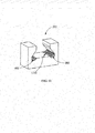
- Suitable mechanisms include, but are not limited to, interference fitting, adhesively securing, a retention mechanism (such as a plug 1102 as shown in FIG. 11 extending from the insert 802 into a groove or other keying region of the component 202), or a combination thereof.
Landscapes
- Engineering & Computer Science (AREA)
- Mechanical Engineering (AREA)
- General Engineering & Computer Science (AREA)
- Turbine Rotor Nozzle Sealing (AREA)
- Structures Of Non-Positive Displacement Pumps (AREA)
- Polishing Bodies And Polishing Tools (AREA)
- Milling Processes (AREA)
Abstract
Description
- The present invention is directed to manufactured components and processes of forming, repairing, or otherwise machining manufactured components. More particularly, the present invention relates to components and processes of preparing, forming, repairing, or otherwise machining components.
- Generally, turbine rotor assemblies include a rotor wheel to which a plurality of blades are coupled. The blades extend radially outward from a platform that extends between an airfoil portion of the blade and a dovetail portion of the blade. The dovetail portion of the blade has at least one pair of dovetail tangs that couples the rotor blade to a complimentary dovetail slot in an outer rim of a rotor wheel.
- Dovetail slots in the outer rim of the rotor wheel are sized to receive the dovetail tangs of the dovetail portion of the blade. These blades receive cooling air from a circumferential slot that intersect with the dovetail. Portions of the dovetail slots where the cooling slot intersects can have high stress regions. Mitigating stress can extend the usable fatigue life of the rotor wheel. The stress is caused by a combination of mechanical cyclic loads and thermal cyclic and static loads which can result in the accumulation of strain over time. The stress can be mitigated by complex processes that can include disassembling components for repair, using robotic heads, and/or using five-axis machines. These processes can suffer from drawbacks that they are expensive, are not widely available, involve complex tooling, and result in the rotor wheel being out of service for a long period of time.
- Other techniques include using a manual grinding operation to remove fatigued material from the dovetail. However, these uncontrolled processes may introduce undesired high stress concentrations into the dovetail, which may result in reducing the component life capability.
- In yet another technique, material may be removed in a concentrated stress region using a controlled break edge method. This method uses a customized edge grinder to follow the contours of the slot edge. Though the shape and consistency of the edge break helps the part meet the intended service life, this method does not significantly reduce the stress nor remove enough strained material to significantly extend the operating life of the feature.
- A process of repairing a component, a repair tool for a component, and a component that do not suffer from one or more of the above drawbacks would be desirable in the art.
- In an first aspect, the invention resides in a process of repairing a component including removing material from a region of the component. The removing forms a through-cut in the component, forms a partial-frustoconical geometry in the component, forms a substantially partial-frustoconical geometry in the component, forms a partial-spherical geometry in the component, forms a substantially partial-spherical geometry in the component, forms a partial-elliptical geometry in the component, forms a substantially partial-elliptical geometry in the component, forms a partial-cylindrical geometry in the component, forms a substantially partial-cylindrical geometry in the component, is in a direction substantially perpendicular to a surface of the component, is in a direction substantially inclined with respect to the surface of the component, or a combination thereof.
- In another aspect, the invention resides in a repair tool for a component including a securing mechanism and a cutting portion. The cutting portion is configured to remove a region of the component, the region having a partial-frustoconical geometry, a substantially partial-frustoconical geometry, a partial-spherical geometry, a substantially partial-spherical geometry, a partial-elliptical geometry, a substantially partial-elliptical geometry, a partial-cylindrical geometry, a substantially partial-cylindrical geometry, or a combination thereof.
- In another aspect, the invention resides in a component including a region formed by removing material. The region is a through-cut, has a partial-frustoconical geometry, has a substantially partial-frustoconical geometry, has a partial-spherical geometry, has a substantially partial-spherical geometry, has a partial-elliptical geometry, has a substantially partial-elliptical geometry, has a partial-cylindrical geometry, has a substantially partial-cylindrical geometry, or a combination thereof.
- Other features and advantages of the present invention will be apparent from the following more detailed description of the preferred embodiment, taken in conjunction with the accompanying drawings which illustrate, by way of example, the principles of the invention.
-
FIG. 1 shows a perspective view of a portion of a turbine including a turbine blade and a turbine rotor wheel. -
FIG. 2 shows a perspective view of a component and a repair tool according to an embodiment of the disclosure. -
FIG. 3 shows a perspective view of a component and a repair tool according to an embodiment of the disclosure. -
FIG. 4 shows a repaired component according to an embodiment of the disclosure. -
FIG. 5 shows a repaired component according to an embodiment of the disclosure. -
FIG. 6 shows a portion of a repaired component according to an embodiment of the disclosure. -
FIG. 7 shows a portion of a repaired component according to an embodiment of the disclosure. -
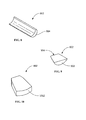
FIG. 8 shows an insert configured for positioning within a component according to an embodiment of the disclosure. -
FIG. 9 shows an insert configured for positioning within a component according to an embodiment of the disclosure. -
FIG. 10 shows an insert configured for positioning within a component according to an embodiment of the disclosure. -
FIG. 11 shows a component with an insert according to an embodiment of the disclosure. - Wherever possible, the same reference numbers will be used throughout the drawings to represent the same parts.
- Provided is a process of repairing a component, a repair tool for a component, and a component. Embodiments of the present disclosure permit extended useful life of components, reduce or eliminate crack propagation, permit increased operational performance of turbines, increase resistance to fatigue, or combinations thereof.
-
FIG. 1 is a perspective view of portions of a turbine 110 including arotor wheel 112 and ablade 114 according to an embodiment. Generally, the turbine 110 includes a plurality of therotor wheels 112,blades 114, and other turbine components (for example, a compressor, a shaft, vanes, rotor dovetails, and/or other suitable components). Fluid (such as gas) enters the turbine 110 (for example, through an inlet) and is channeled (for example, through the vanes) downstream against theblades 114 and through the remaining stages imparting a force on theblades 114 causingrotor wheels 112 to rotate (for example, around the shaft) or vice versa. The turbine 110 is operably connected to any suitable load (for example, a generator, another turbine, or combinations thereof) thereby permitting the extraction of energy and/or generation of thrust. In one embodiment, the turbine is configured for power generation. In another embodiment, the turbine is an aviation turbine. - The
blades 114 mechanically couple to therotor wheels 112. Theblades 114 are positioned within a turbine stage of the turbine 110, thereby exposing theblades 114 to forces such as high temperatures (for example, between about 1000° F and about 2000° F, about 1000° F, about 1250° F, about 1500° F, about 2000° F, or about 3000° F) from hot gases passing through the turbine stage and/or any suitable temperature range (for example, above about 59° F, between about 59° F and about 3000° F, between about 59° F and about 1000° F, between about 59° F and about 1250° F, between about 59° F and about 1500° F, between about 59° F and about 2000° F, or at about 59° F). In one embodiment, one or more of theblades 114 includes aplatform 116, anairfoil 118 extending fromplatform 116, and ablade dovetail 122. Theblade dovetail 122 includes at least one pair ofdovetail tangs 124 used for coupling theblade 114 to therotor wheel 112. - The
rotor wheel 112 includes adovetail slot 126 corresponding to theblade dovetail 122. Therotor wheels 112 are positioned within the turbine stage of the turbine 110 thereby exposing therotor wheels 112 to forces such as temperatures just below the temperatures of the hot gas path (for example, between about 800° F and about 1250° F, about 800° F, about 1000° F, about 1250° F, about 1500° F, or about 2000° F) and/or any suitable temperature range (for example, above about 59° F, between about 59° F and about 3000° F, between about 59° F and about 1000° F, between about 59° F and about 1250° F, between about 59° F and about 1500° F, between about 59° F and about 2000° F, or at about 59° F). Thedovetail slot 126 is sized and shaped to receive theblade dovetail 122. -
FIGS. 2 and 3 show embodiments of arepair tool 200 positioned to perform a repair method on a component 202 (such as a turbine component, a compressor component, and/or any other suitable component). Therepair tool 200 includes acutting portion 204 for removing material from thecomponent 202 and apositioning mechanism 206 for positioning and operating thetool 200. In one embodiment, thepositioning mechanism 206 is positioned to permit thetool 200 to contact the component 202 (for example, therotor wheel 112 or a portion of the rotor wheel 112). Thepositioning mechanism 206 includes any suitable features, such as, but not limited to, a stop mechanism 308 (seeFIG. 3 ) preventing the cutting from being beyond the predetermined depth, aguide mechanism 208 for directing the cutting along a desired direction orpath 212, other suitable features for permitting repeated and precise cutting without complex tools or substantial training of technicians, or a combination thereof. - In one embodiment, the
positioning mechanism 206 is capable of being positioned at only one angle, a set of angles, or a range of angles. For example, as shown inFIG. 2 , in one embodiment, thepositioning mechanism 206 permits only linear movement, inclined movement, and/or movement perpendicular to asurface 210 of thecomponent 202 along thepath 212. In this embodiment, thecomponent 202 is capable of being machined/repaired by forming a through-cut 402, as shown inFIG. 4 . As used herein, the term through-cut refers to a removed region that extends from a first surface, such as thesurface 210, to a second surface, such as a surface (not shown) opposite thesurface 210. - In one embodiment, as shown in
FIG. 3 , thepositioning mechanism 206 permits only linear movement and/or movement at an incline with respect to thesurface 210 of thecomponent 202 along thepath 212. In this embodiment, thecomponent 202 is capable of being machined/repaired by forming a removed region that is aninclined cut 502, a partial-frustoconical region 504, or a combination thereof, as shown inFIG. 5 . - Referring again to
FIGS. 2 and 3 , the amount and position of material removed from thecomponent 202 are based upon the geometry of thecutting portion 204 of thetool 200 and the operation of thetool 200. For example, in one embodiment, thetool 200 is used in a single-pass removal. In this embodiment, the amount of material closely coincides with the shape of thecutting portion 204. In another embodiment, thetool 200 is used in a multiple-pass removal. In this embodiment, the amount of material either closely coincides with the shape of the cuttingportion 204 or slightly exceeds the size of the cuttingportion 204 due to slight variations between positioning of thetool 200 during each pass. - In one embodiment, the
tool 200 removes a region from thecomponent 202 having a maximum width (for example, between about 0.25 inches and about 20 inches, between about 0.50 inches and about 10 inches, greater than about 0.25 inches, greater than about 0.50 inches, greater than about 10 inches, or any suitable range, sub-range, combination, or sub-combination thereof) resulting from inserting the repair tool 200 a predetermined depth. In this embodiment, the cuttingportion 204 of thetool 200 is cylindrical and tapered, frustoconical, elliptical, spherical, tapered, or a combination thereof to remove the portion of the frustoconical shape. In another embodiment, the cuttingportion 204 includes a conical geometry, a spherical geometry, or a combination thereof. In one embodiment, the region removed is a through-cut, has a partial-frustoconical geometry, has a substantially partial-frustoconical geometry, has a partial-spherical geometry, has a substantially partial-spherical geometry, has a partial-elliptical geometry, has a substantially partial-elliptical geometry, has a partial-cylindrical geometry, has a substantially partial-cylindrical geometry, or a combination thereof. - The cutting
portion 204 is any suitable material. In one embodiment, the cuttingportion 204 is a carbide portion or other suitable cutting material. In one embodiment, the cuttingportion 204 includes a material harder than the material of thecomponent 202. - Referring to
FIG. 6 , in one embodiment, thetool 200 machines/removes a portion of thecomponent 202 corresponding to a stress profile. For example, in one embodiment, thetool 200 removes ahoop stress region 602, for example, a region of a portion of thecomponent 202 or theentire component 202 subjected to the greatest amount of hoop stress during operation of thecomponent 202. Additionally or alternatively, in one embodiment, thetool 200 removes aradial stress region 604, for example, a region of a portion of thecomponent 202 or theentire component 202 subjected to the greatest amount of radial stress during operation of thecomponent 202. - Referring to
FIG. 7 , in one embodiment, thetool 200 machines/removes material to expand from a cylindrical, generally cylindrical, or frustoconical region and forms a substantially partial-frustoconical region 702 having slight variations from being curved. In one embodiment, the additional material is machined/removed by additional passes by thetool 200. In a further embodiment, the additional removed material corresponds with thehoop stress region 602 and theradial stress region 604 described above with reference toFIG. 6 . - Referring to
FIGS. 8-10 , in one embodiment, thecomponent 202 includes aninsert 802 having a geometry corresponding to a portion of thecomponent 202. In one embodiment, theinsert 802 has a geometry corresponding with the through-cut 402, for example, an elongate half-moon geometry 804 as shown inFIG. 8 . In one embodiment, as shown inFIG. 9 , theinsert 802 has a geometry corresponding to theinclined cut 502, for example, a narrowingcomplex geometry 902, and/or to the partial-frustoconical region 504, for example, acomplex geometry 904. In one embodiment, theinsert 802 has a geometry corresponding to the substantially partial-frustoconical region 702, for example, acomplex geometry 1002 as shown inFIG. 10 . In further embodiments, theinsert 802 includes a combination of any of these geometries. - In one embodiment, the
insert 802 is positioned within the through-cut 402 (seeFIG. 4 ), the inclined cut 502 (seeFIG. 5 ), the partial-frustoconical region (seeFIG. 6 ), the substantially partial-frustoconical region 702 (seeFIG. 7 ), abutting the hoop stress region 602 (seeFIG. 6 ), abutting the radial stress region 604 (seeFIG. 6 ), in place of the hoop stress region 602 (seeFIG. 6 ), in place of the radial stress region 604 (seeFIG. 6 ), or a combination thereof. Theinsert 802 is secured by any suitable mechanism upon being positioned. Suitable mechanisms include, but are not limited to, interference fitting, adhesively securing, a retention mechanism (such as aplug 1102 as shown inFIG. 11 extending from theinsert 802 into a groove or other keying region of the component 202), or a combination thereof. - While the invention has been described with reference to a preferred embodiment, it will be understood by those skilled in the art that various changes may be made and equivalents may be substituted for elements thereof without departing from the scope of the invention. In addition, many modifications may be made to adapt a particular situation or material to the teachings of the invention without departing from the essential scope thereof. Therefore, it is intended that the invention not be limited to the particular embodiment disclosed as the best mode contemplated for carrying out this invention, but that the invention will include all embodiments falling within the scope of the appended claims.
- Various aspects and embodiments of the present invention are defined by the following numbered clauses:
- 1. A component, comprising:
- a region formed by removing material;
- wherein the region is a through-cut, has a partial-frustoconical geometry, has a substantially partial-frustoconical geometry, has a partial-spherical geometry, has a substantially partial-spherical geometry, has a partial-elliptical geometry, has a substantially partial-elliptical geometry, has a partial-cylindrical geometry, has a substantially partial-cylindrical geometry, or a combination thereof.
- 2. The component of clause 1, wherein the region is at least partially filled with an insert.
- 3. The component of clause 1 or 2, wherein the component is selected from the group consisting of a turbine wheel, a turbine shaft, a turbine vane, a rotor dovetail, and a combination thereof.
- 4. The component of any preceding clause, wherein the region extends in a direction perpendicular to a surface of the component.
- 5. The component of any preceding clause, wherein the region extends at an incline with respect to a surface of the component.
Claims (15)
- A process of repairing a component (202), the process comprising:removing material from a region of the component (202);wherein the removing forms a through-cut in the component, forms a partial-frustoconical geometry in the component, forms a substantially partial-frustoconical geometry in the component (202), forms a substantially partial-spherical geometry in the component (202), forms a substantially partial-elliptical geometry in the component (202), forms a substantially partial-cylindrical geometry in the component (202), is in a direction substantially perpendicular to a surface (210) of the component (202), is in a direction substantially inclined with respect to the surface (210) of the component (202), or a combination thereof.
- The process of claim 1, wherein the removing is a single-pass removal.
- The process of claim 1 or 2, wherein the removing is by a machining action along a substantially linear path.
- The process of any of claims 1 to 3, further comprising positioning an insert (802) at least partially within the region.
- The process of claim 4, wherein the insert (802) is secured to the region by an interference fit, a retention mechanism, or a combination thereof.
- The process of claim 4 or 5, wherein the insert (802) includes an elongate half-moon geometry (804).
- The process of claim 4 or 5, wherein the insert (802) includes a geometry corresponding to the through-cut (402).
- The process of claim 4 or 5, wherein the insert (802) includes a geometry corresponding to the substantially partial-frustoconical geometry.
- The process of any of claims 4 to 8, wherein the positioning of the insert (802) is in place of a radial stress region (604), a hoop stress region (602), or both.
- The process of any preceding claim, wherein the component (202) is selected from the group consisting of a turbine wheel, a turbine shaft, a turbine vane, a rotor dovetail, and a combination thereof.
- The process of any preceding claim, wherein the region is at an incline with respect to a surface (210) of the component (202).
- A repair tool (200) for a component (202), the repair tool comprising:a securing mechanism (206); anda cutting portion (204);wherein the cutting portion (204) is configured to remove a region of the component (202), the region having a substantially partial-frustoconical geometry, a substantially partial-spherical geometry, a substantially partial-elliptical geometry, a substantially partial-cylindrical geometry, or a combination thereof.
- The repair tool of claim 12, wherein the region extends perpendicular to a surface (210) of the component (202).
- The repair tool of claim 12, wherein the region extends at an incline with respect to a surface (210) of the component (202).
- A component, repaired by the method of any of claims 1 to 11.
Applications Claiming Priority (1)
| Application Number | Priority Date | Filing Date | Title |
|---|---|---|---|
| US13/426,031 US8959738B2 (en) | 2012-03-21 | 2012-03-21 | Process of repairing a component, a repair tool for a component, and a component |
Publications (2)
| Publication Number | Publication Date |
|---|---|
| EP2642074A1 true EP2642074A1 (en) | 2013-09-25 |
| EP2642074B1 EP2642074B1 (en) | 2015-09-02 |
Family
ID=47913038
Family Applications (1)
| Application Number | Title | Priority Date | Filing Date |
|---|---|---|---|
| EP13159412.9A Active EP2642074B1 (en) | 2012-03-21 | 2013-03-15 | Process of repairing a component, a repair tool for a component, and a component |
Country Status (5)
| Country | Link |
|---|---|
| US (1) | US8959738B2 (en) |
| EP (1) | EP2642074B1 (en) |
| JP (1) | JP2013193205A (en) |
| CN (1) | CN103321691B (en) |
| RU (1) | RU2013112150A (en) |
Cited By (4)
| Publication number | Priority date | Publication date | Assignee | Title |
|---|---|---|---|---|
| FR3027071A1 (en) * | 2014-10-13 | 2016-04-15 | Snecma | METHOD OF INTERVENTION ON A ROTOR AND ASSOCIATED CLINKER |
| EP3167989A1 (en) * | 2015-11-16 | 2017-05-17 | Siemens Aktiengesellschaft | Milling device and method for carrying out milling inside a groove |
| GB2547291A (en) * | 2015-07-21 | 2017-08-16 | Gen Electric | Method and system for repairing turbomachine dovetail slots |
| EP3301255A1 (en) * | 2016-09-30 | 2018-04-04 | Siemens Aktiengesellschaft | Methods for operating and treating a turbine assembly |
Families Citing this family (10)
| Publication number | Priority date | Publication date | Assignee | Title |
|---|---|---|---|---|
| US8813331B2 (en) | 2011-03-29 | 2014-08-26 | General Electric Company | Process of preparing a turbine rotor wheel, a repair wheel for a turbine rotor wheel, and a turbine rotor wheel |
| CH705377A1 (en) * | 2011-08-09 | 2013-02-15 | Alstom Technology Ltd | A process for reconditioning a rotor of a turbomachine. |
| JP5922370B2 (en) * | 2011-10-20 | 2016-05-24 | 三菱日立パワーシステムズ株式会社 | Rotor blade support structure |
| US10024162B2 (en) * | 2013-03-14 | 2018-07-17 | United Technologies Corporation | Turbine disk fatigue rejuvenation |
| EP2781691A1 (en) * | 2013-03-19 | 2014-09-24 | Alstom Technology Ltd | Method for reconditioning a hot gas path part of a gas turbine |
| JP2017064823A (en) * | 2015-09-29 | 2017-04-06 | 株式会社Ihi | Working apparatus |
| US10005139B2 (en) * | 2015-12-21 | 2018-06-26 | General Electric Company | Portable milling tool with method for turbomachine milling |
| US11098729B2 (en) * | 2016-08-04 | 2021-08-24 | General Electric Company | Gas turbine wheel assembly, method of modifying a compressor wheel, and method of mounting a blade to a gas turbine wheel |
| DE102018208708A1 (en) * | 2018-06-04 | 2019-12-05 | MTU Aero Engines AG | METHOD FOR OVERHAULING A SHAFT WHEEL OF A FLOW MACHINE |
| DE102022202368A1 (en) | 2022-03-10 | 2023-09-14 | Siemens Energy Global GmbH & Co. KG | Groove design of a disk for a turbine blade, rotor and process |
Citations (3)
| Publication number | Priority date | Publication date | Assignee | Title |
|---|---|---|---|---|
| US6238187B1 (en) * | 1999-10-14 | 2001-05-29 | Lsp Technologies, Inc. | Method using laser shock peening to process airfoil weld repairs pertaining to blade cut and weld techniques |
| EP1231010A1 (en) * | 2001-02-08 | 2002-08-14 | Siemens Westinghouse Power Corporation | Transient liquid phase bonding repair for turbine blades and vanes |
| US20030082048A1 (en) * | 2001-10-22 | 2003-05-01 | Jackson Melvin Robert | Airfoils with improved strength and manufacture and repair thereof |
Family Cites Families (31)
| Publication number | Priority date | Publication date | Assignee | Title |
|---|---|---|---|---|
| US4477226A (en) | 1983-05-09 | 1984-10-16 | General Electric Company | Balance for rotating member |
| US5846054A (en) * | 1994-10-06 | 1998-12-08 | General Electric Company | Laser shock peened dovetails for disks and blades |
| US6199746B1 (en) * | 1999-08-02 | 2001-03-13 | General Electric Company | Method for preparing superalloy castings using a metallurgically bonded tapered plug |
| FR2816538B1 (en) * | 2000-11-16 | 2003-01-17 | Snecma Moteurs | PROCESS FOR INCREASING THE LIFETIME OF AUB ATTACHES ON A ROTOR |
| US6551032B1 (en) | 2001-11-07 | 2003-04-22 | General Electric Company | Multi-part dovetail repair broach assembly and methods of use |
| US6676336B2 (en) | 2001-11-13 | 2004-01-13 | General Electric Company | Multi-part dovetail repair broach assembly and methods of use |
| US6837685B2 (en) | 2002-12-13 | 2005-01-04 | General Electric Company | Methods and apparatus for repairing a rotor assembly of a turbine |
| JP4000075B2 (en) * | 2003-02-27 | 2007-10-31 | 株式会社東芝 | Rotor repair method |
| US8122600B2 (en) | 2003-03-03 | 2012-02-28 | United Technologies Corporation | Fan and compressor blade dovetail restoration process |
| US7146725B2 (en) * | 2003-05-06 | 2006-12-12 | Siemens Power Generation, Inc. | Repair of combustion turbine components |
| US6849972B1 (en) | 2003-08-27 | 2005-02-01 | General Electric Company | Generator rotor fretting fatigue crack repair |
| US8573901B2 (en) * | 2003-09-02 | 2013-11-05 | Kennametal Inc. | Assembly for rotating a cutting insert during a turning operation and inserts used therein |
| EP1738059A1 (en) * | 2004-03-15 | 2007-01-03 | Digga Australia Pty Ltd | Rotatable cutting tool |
| US7093360B1 (en) * | 2004-04-06 | 2006-08-22 | Craig Merrill C | Method of removing boiler tubes |
| FR2871399B1 (en) * | 2004-06-15 | 2006-09-22 | Snecma Moteurs Sa | PROCESS FOR REPAIRING A DAWN ELEMENT |
| US7690111B2 (en) * | 2005-04-14 | 2010-04-06 | Mechanical Dynamics And Analysis, Llc | Method and apparatus for repairing turbine rotor |
| US7690896B2 (en) | 2005-05-27 | 2010-04-06 | United Technologies Corporation | Gas turbine disk slots and gas turbine engine using same |
| US20070039176A1 (en) * | 2005-08-01 | 2007-02-22 | Kelly Thomas J | Method for restoring portion of turbine component |
| US20070267109A1 (en) | 2006-05-17 | 2007-11-22 | General Electric Company | High pressure turbine airfoil recovery device and method of heat treatment |
| US7901187B2 (en) * | 2006-06-23 | 2011-03-08 | Siemens Energy, Inc. | Turbine rotor blade groove entry slot lock structure |
| US7858897B2 (en) * | 2006-10-27 | 2010-12-28 | United Technologies Corporation | Insert weld repair |
| US8051565B2 (en) | 2006-12-30 | 2011-11-08 | General Electric Company | Method for increasing fatigue notch capability of airfoils |
| US20090057275A1 (en) * | 2007-08-31 | 2009-03-05 | General Electric Company | Method of Repairing Nickel-Based Alloy Articles |
| US7836594B2 (en) * | 2007-10-16 | 2010-11-23 | United Technologies Corporation | Method for restoring airfoil tip contour |
| US20090142548A1 (en) * | 2007-10-18 | 2009-06-04 | David Bruce Patterson | Air cooled gas turbine components and methods of manufacturing and repairing the same |
| US8182229B2 (en) | 2008-01-14 | 2012-05-22 | General Electric Company | Methods and apparatus to repair a rotor disk for a gas turbine |
| DE102008049055B4 (en) * | 2008-09-26 | 2010-08-05 | Lufthansa Technik Ag | Method for repairing a housing flange of an aircraft engine |
| US8347479B2 (en) * | 2009-08-04 | 2013-01-08 | The United States Of America As Represented By The United States National Aeronautics And Space Administration | Method for repairing cracks in structures |
| US8813331B2 (en) * | 2011-03-29 | 2014-08-26 | General Electric Company | Process of preparing a turbine rotor wheel, a repair wheel for a turbine rotor wheel, and a turbine rotor wheel |
| US20130232792A1 (en) * | 2012-03-12 | 2013-09-12 | General Electric Company | Apparatus and method for servicing turbomachinery components in-situ |
| US20140223709A1 (en) * | 2013-02-08 | 2014-08-14 | General Electric Company | Turbomachine rotor blade milling machine system and method of field repairing a turbomachine rotor blade |
-
2012
- 2012-03-21 US US13/426,031 patent/US8959738B2/en active Active
-
2013
- 2013-03-15 EP EP13159412.9A patent/EP2642074B1/en active Active
- 2013-03-19 JP JP2013055846A patent/JP2013193205A/en active Pending
- 2013-03-20 RU RU2013112150/02A patent/RU2013112150A/en not_active Application Discontinuation
- 2013-03-21 CN CN201310092311.0A patent/CN103321691B/en active Active
Patent Citations (3)
| Publication number | Priority date | Publication date | Assignee | Title |
|---|---|---|---|---|
| US6238187B1 (en) * | 1999-10-14 | 2001-05-29 | Lsp Technologies, Inc. | Method using laser shock peening to process airfoil weld repairs pertaining to blade cut and weld techniques |
| EP1231010A1 (en) * | 2001-02-08 | 2002-08-14 | Siemens Westinghouse Power Corporation | Transient liquid phase bonding repair for turbine blades and vanes |
| US20030082048A1 (en) * | 2001-10-22 | 2003-05-01 | Jackson Melvin Robert | Airfoils with improved strength and manufacture and repair thereof |
Cited By (10)
| Publication number | Priority date | Publication date | Assignee | Title |
|---|---|---|---|---|
| FR3027071A1 (en) * | 2014-10-13 | 2016-04-15 | Snecma | METHOD OF INTERVENTION ON A ROTOR AND ASSOCIATED CLINKER |
| WO2016059338A1 (en) * | 2014-10-13 | 2016-04-21 | Snecma | Method for carrying out work on a rotor and associated foil |
| CN107109944A (en) * | 2014-10-13 | 2017-08-29 | 赛峰航空器发动机 | Implement the method and its associated patch of operation on rotor |
| CN107109944B (en) * | 2014-10-13 | 2019-08-13 | 赛峰航空器发动机 | Method of performing work on a rotor and associated linings |
| US10677074B2 (en) | 2014-10-13 | 2020-06-09 | Safran Aircraft Engines | Method for carrying out work on a rotor and associated foil |
| GB2547291A (en) * | 2015-07-21 | 2017-08-16 | Gen Electric | Method and system for repairing turbomachine dovetail slots |
| GB2547291B (en) * | 2015-07-21 | 2018-02-07 | Gen Electric | Method and system for repairing turbomachine dovetail slots |
| EP3167989A1 (en) * | 2015-11-16 | 2017-05-17 | Siemens Aktiengesellschaft | Milling device and method for carrying out milling inside a groove |
| DE102015222529A1 (en) * | 2015-11-16 | 2017-05-18 | Siemens Aktiengesellschaft | Milling device and method for performing a milling operation within a groove |
| EP3301255A1 (en) * | 2016-09-30 | 2018-04-04 | Siemens Aktiengesellschaft | Methods for operating and treating a turbine assembly |
Also Published As
| Publication number | Publication date |
|---|---|
| EP2642074B1 (en) | 2015-09-02 |
| RU2013112150A (en) | 2014-09-27 |
| CN103321691B (en) | 2017-06-06 |
| CN103321691A (en) | 2013-09-25 |
| US20130247377A1 (en) | 2013-09-26 |
| JP2013193205A (en) | 2013-09-30 |
| US8959738B2 (en) | 2015-02-24 |
Similar Documents
| Publication | Publication Date | Title |
|---|---|---|
| US8959738B2 (en) | Process of repairing a component, a repair tool for a component, and a component | |
| US8813331B2 (en) | Process of preparing a turbine rotor wheel, a repair wheel for a turbine rotor wheel, and a turbine rotor wheel | |
| US6302625B1 (en) | Method and apparatus for refurbishing a gas turbine airfoil | |
| EP2116691B1 (en) | Method for repairing a stator assembly of a gas turbine engine and gas turbine engine component | |
| EP3152403B1 (en) | Turbine blisk and method of manufacturing thereof | |
| US20080304972A1 (en) | Rotary body for turbo machinery with mistuned blades | |
| EP2339117B1 (en) | Consumable collar for linear friction welding of blade replacement for damaged integrally blades rotors | |
| CA2802849C (en) | Method of servicing an airfoil assembly for use in a gas turbine engine | |
| US9163511B2 (en) | Steam turbine bucket tenon restoration through solid state bonding process | |
| EP2159371B1 (en) | Gas turbine airfoil assemblies and methods of repair | |
| EP2955329A1 (en) | Integrally formed rotor assembly with shaft and blisks | |
| CA3015255C (en) | Device and method for re-contouring a gas turbine blade | |
| WO2013158483A1 (en) | Trapped spring balance weight and rotor assembly | |
| EP2938832B1 (en) | Shrouded turbine blade with cut corner | |
| EP2803819A1 (en) | Modified turbine buckets and methods for modifying turbine buckets | |
| CN107687445B (en) | Impeller assembly, method of modifying an impeller and method of mounting blades to an impeller | |
| EP2804718B1 (en) | Method of surface treatment for dovetail in gas turbine engine fan blade | |
| EP3070267A1 (en) | Method and device for assembling blades into a gas turbine disc by providing heat in order to creat a blade pre-twist | |
| WO2013130290A1 (en) | Component blending tool assembly | |
| EP3163015A1 (en) | Power nozzle repair with cooling hardware installed | |
| EP3887651A1 (en) | Platform seal and damper assembly for turbomachinery and methodology for forming said assembly |
Legal Events
| Date | Code | Title | Description |
|---|---|---|---|
| PUAI | Public reference made under article 153(3) epc to a published international application that has entered the european phase |
Free format text: ORIGINAL CODE: 0009012 |
|
| AK | Designated contracting states |
Kind code of ref document: A1 Designated state(s): AL AT BE BG CH CY CZ DE DK EE ES FI FR GB GR HR HU IE IS IT LI LT LU LV MC MK MT NL NO PL PT RO RS SE SI SK SM TR |
|
| AX | Request for extension of the european patent |
Extension state: BA ME |
|
| 17P | Request for examination filed |
Effective date: 20140325 |
|
| RBV | Designated contracting states (corrected) |
Designated state(s): AL AT BE BG CH CY CZ DE DK EE ES FI FR GB GR HR HU IE IS IT LI LT LU LV MC MK MT NL NO PL PT RO RS SE SI SK SM TR |
|
| GRAP | Despatch of communication of intention to grant a patent |
Free format text: ORIGINAL CODE: EPIDOSNIGR1 |
|
| INTG | Intention to grant announced |
Effective date: 20150310 |
|
| GRAP | Despatch of communication of intention to grant a patent |
Free format text: ORIGINAL CODE: EPIDOSNIGR1 |
|
| GRAS | Grant fee paid |
Free format text: ORIGINAL CODE: EPIDOSNIGR3 |
|
| INTG | Intention to grant announced |
Effective date: 20150703 |
|
| GRAA | (expected) grant |
Free format text: ORIGINAL CODE: 0009210 |
|
| AK | Designated contracting states |
Kind code of ref document: B1 Designated state(s): AL AT BE BG CH CY CZ DE DK EE ES FI FR GB GR HR HU IE IS IT LI LT LU LV MC MK MT NL NO PL PT RO RS SE SI SK SM TR |
|
| REG | Reference to a national code |
Ref country code: GB Ref legal event code: FG4D |
|
| REG | Reference to a national code |
Ref country code: AT Ref legal event code: REF Ref document number: 746757 Country of ref document: AT Kind code of ref document: T Effective date: 20150915 Ref country code: CH Ref legal event code: EP |
|
| REG | Reference to a national code |
Ref country code: IE Ref legal event code: FG4D |
|
| REG | Reference to a national code |
Ref country code: DE Ref legal event code: R096 Ref document number: 602013002774 Country of ref document: DE |
|
| REG | Reference to a national code |
Ref country code: AT Ref legal event code: MK05 Ref document number: 746757 Country of ref document: AT Kind code of ref document: T Effective date: 20150902 |
|
| PG25 | Lapsed in a contracting state [announced via postgrant information from national office to epo] |
Ref country code: FI Free format text: LAPSE BECAUSE OF FAILURE TO SUBMIT A TRANSLATION OF THE DESCRIPTION OR TO PAY THE FEE WITHIN THE PRESCRIBED TIME-LIMIT Effective date: 20150902 Ref country code: NO Free format text: LAPSE BECAUSE OF FAILURE TO SUBMIT A TRANSLATION OF THE DESCRIPTION OR TO PAY THE FEE WITHIN THE PRESCRIBED TIME-LIMIT Effective date: 20151202 Ref country code: GR Free format text: LAPSE BECAUSE OF FAILURE TO SUBMIT A TRANSLATION OF THE DESCRIPTION OR TO PAY THE FEE WITHIN THE PRESCRIBED TIME-LIMIT Effective date: 20151203 Ref country code: LV Free format text: LAPSE BECAUSE OF FAILURE TO SUBMIT A TRANSLATION OF THE DESCRIPTION OR TO PAY THE FEE WITHIN THE PRESCRIBED TIME-LIMIT Effective date: 20150902 Ref country code: LT Free format text: LAPSE BECAUSE OF FAILURE TO SUBMIT A TRANSLATION OF THE DESCRIPTION OR TO PAY THE FEE WITHIN THE PRESCRIBED TIME-LIMIT Effective date: 20150902 |
|
| REG | Reference to a national code |
Ref country code: LT Ref legal event code: MG4D Ref country code: NL Ref legal event code: MP Effective date: 20150902 |
|
| PG25 | Lapsed in a contracting state [announced via postgrant information from national office to epo] |
Ref country code: RS Free format text: LAPSE BECAUSE OF FAILURE TO SUBMIT A TRANSLATION OF THE DESCRIPTION OR TO PAY THE FEE WITHIN THE PRESCRIBED TIME-LIMIT Effective date: 20150902 Ref country code: AT Free format text: LAPSE BECAUSE OF FAILURE TO SUBMIT A TRANSLATION OF THE DESCRIPTION OR TO PAY THE FEE WITHIN THE PRESCRIBED TIME-LIMIT Effective date: 20150902 Ref country code: SE Free format text: LAPSE BECAUSE OF FAILURE TO SUBMIT A TRANSLATION OF THE DESCRIPTION OR TO PAY THE FEE WITHIN THE PRESCRIBED TIME-LIMIT Effective date: 20150902 Ref country code: ES Free format text: LAPSE BECAUSE OF FAILURE TO SUBMIT A TRANSLATION OF THE DESCRIPTION OR TO PAY THE FEE WITHIN THE PRESCRIBED TIME-LIMIT Effective date: 20150902 Ref country code: PL Free format text: LAPSE BECAUSE OF FAILURE TO SUBMIT A TRANSLATION OF THE DESCRIPTION OR TO PAY THE FEE WITHIN THE PRESCRIBED TIME-LIMIT Effective date: 20150902 |
|
| PG25 | Lapsed in a contracting state [announced via postgrant information from national office to epo] |
Ref country code: IS Free format text: LAPSE BECAUSE OF FAILURE TO SUBMIT A TRANSLATION OF THE DESCRIPTION OR TO PAY THE FEE WITHIN THE PRESCRIBED TIME-LIMIT Effective date: 20160102 Ref country code: CZ Free format text: LAPSE BECAUSE OF FAILURE TO SUBMIT A TRANSLATION OF THE DESCRIPTION OR TO PAY THE FEE WITHIN THE PRESCRIBED TIME-LIMIT Effective date: 20150902 Ref country code: IT Free format text: LAPSE BECAUSE OF FAILURE TO SUBMIT A TRANSLATION OF THE DESCRIPTION OR TO PAY THE FEE WITHIN THE PRESCRIBED TIME-LIMIT Effective date: 20150902 Ref country code: EE Free format text: LAPSE BECAUSE OF FAILURE TO SUBMIT A TRANSLATION OF THE DESCRIPTION OR TO PAY THE FEE WITHIN THE PRESCRIBED TIME-LIMIT Effective date: 20150902 Ref country code: NL Free format text: LAPSE BECAUSE OF FAILURE TO SUBMIT A TRANSLATION OF THE DESCRIPTION OR TO PAY THE FEE WITHIN THE PRESCRIBED TIME-LIMIT Effective date: 20150902 Ref country code: SK Free format text: LAPSE BECAUSE OF FAILURE TO SUBMIT A TRANSLATION OF THE DESCRIPTION OR TO PAY THE FEE WITHIN THE PRESCRIBED TIME-LIMIT Effective date: 20150902 |
|
| PG25 | Lapsed in a contracting state [announced via postgrant information from national office to epo] |
Ref country code: RO Free format text: LAPSE BECAUSE OF FAILURE TO SUBMIT A TRANSLATION OF THE DESCRIPTION OR TO PAY THE FEE WITHIN THE PRESCRIBED TIME-LIMIT Effective date: 20150902 Ref country code: PT Free format text: LAPSE BECAUSE OF FAILURE TO SUBMIT A TRANSLATION OF THE DESCRIPTION OR TO PAY THE FEE WITHIN THE PRESCRIBED TIME-LIMIT Effective date: 20160104 |
|
| REG | Reference to a national code |
Ref country code: DE Ref legal event code: R097 Ref document number: 602013002774 Country of ref document: DE |
|
| PLBE | No opposition filed within time limit |
Free format text: ORIGINAL CODE: 0009261 |
|
| STAA | Information on the status of an ep patent application or granted ep patent |
Free format text: STATUS: NO OPPOSITION FILED WITHIN TIME LIMIT |
|
| 26N | No opposition filed |
Effective date: 20160603 |
|
| PG25 | Lapsed in a contracting state [announced via postgrant information from national office to epo] |
Ref country code: DK Free format text: LAPSE BECAUSE OF FAILURE TO SUBMIT A TRANSLATION OF THE DESCRIPTION OR TO PAY THE FEE WITHIN THE PRESCRIBED TIME-LIMIT Effective date: 20150902 Ref country code: SI Free format text: LAPSE BECAUSE OF FAILURE TO SUBMIT A TRANSLATION OF THE DESCRIPTION OR TO PAY THE FEE WITHIN THE PRESCRIBED TIME-LIMIT Effective date: 20150902 Ref country code: BE Free format text: LAPSE BECAUSE OF NON-PAYMENT OF DUE FEES Effective date: 20160331 |
|
| PG25 | Lapsed in a contracting state [announced via postgrant information from national office to epo] |
Ref country code: MC Free format text: LAPSE BECAUSE OF FAILURE TO SUBMIT A TRANSLATION OF THE DESCRIPTION OR TO PAY THE FEE WITHIN THE PRESCRIBED TIME-LIMIT Effective date: 20150902 Ref country code: LU Free format text: LAPSE BECAUSE OF FAILURE TO SUBMIT A TRANSLATION OF THE DESCRIPTION OR TO PAY THE FEE WITHIN THE PRESCRIBED TIME-LIMIT Effective date: 20160315 |
|
| REG | Reference to a national code |
Ref country code: CH Ref legal event code: PL |
|
| REG | Reference to a national code |
Ref country code: IE Ref legal event code: MM4A |
|
| PG25 | Lapsed in a contracting state [announced via postgrant information from national office to epo] |
Ref country code: BE Free format text: LAPSE BECAUSE OF FAILURE TO SUBMIT A TRANSLATION OF THE DESCRIPTION OR TO PAY THE FEE WITHIN THE PRESCRIBED TIME-LIMIT Effective date: 20150902 |
|
| REG | Reference to a national code |
Ref country code: FR Ref legal event code: ST Effective date: 20161130 |
|
| PG25 | Lapsed in a contracting state [announced via postgrant information from national office to epo] |
Ref country code: FR Free format text: LAPSE BECAUSE OF NON-PAYMENT OF DUE FEES Effective date: 20160331 Ref country code: CH Free format text: LAPSE BECAUSE OF NON-PAYMENT OF DUE FEES Effective date: 20160331 Ref country code: IE Free format text: LAPSE BECAUSE OF NON-PAYMENT OF DUE FEES Effective date: 20160315 Ref country code: LI Free format text: LAPSE BECAUSE OF NON-PAYMENT OF DUE FEES Effective date: 20160331 |
|
| PG25 | Lapsed in a contracting state [announced via postgrant information from national office to epo] |
Ref country code: MT Free format text: LAPSE BECAUSE OF FAILURE TO SUBMIT A TRANSLATION OF THE DESCRIPTION OR TO PAY THE FEE WITHIN THE PRESCRIBED TIME-LIMIT Effective date: 20150902 |
|
| GBPC | Gb: european patent ceased through non-payment of renewal fee |
Effective date: 20170315 |
|
| PG25 | Lapsed in a contracting state [announced via postgrant information from national office to epo] |
Ref country code: GB Free format text: LAPSE BECAUSE OF NON-PAYMENT OF DUE FEES Effective date: 20170315 |
|
| PG25 | Lapsed in a contracting state [announced via postgrant information from national office to epo] |
Ref country code: CY Free format text: LAPSE BECAUSE OF FAILURE TO SUBMIT A TRANSLATION OF THE DESCRIPTION OR TO PAY THE FEE WITHIN THE PRESCRIBED TIME-LIMIT Effective date: 20150902 Ref country code: SM Free format text: LAPSE BECAUSE OF FAILURE TO SUBMIT A TRANSLATION OF THE DESCRIPTION OR TO PAY THE FEE WITHIN THE PRESCRIBED TIME-LIMIT Effective date: 20150902 Ref country code: HU Free format text: LAPSE BECAUSE OF FAILURE TO SUBMIT A TRANSLATION OF THE DESCRIPTION OR TO PAY THE FEE WITHIN THE PRESCRIBED TIME-LIMIT; INVALID AB INITIO Effective date: 20130315 |
|
| PG25 | Lapsed in a contracting state [announced via postgrant information from national office to epo] |
Ref country code: HR Free format text: LAPSE BECAUSE OF FAILURE TO SUBMIT A TRANSLATION OF THE DESCRIPTION OR TO PAY THE FEE WITHIN THE PRESCRIBED TIME-LIMIT Effective date: 20150902 Ref country code: TR Free format text: LAPSE BECAUSE OF FAILURE TO SUBMIT A TRANSLATION OF THE DESCRIPTION OR TO PAY THE FEE WITHIN THE PRESCRIBED TIME-LIMIT Effective date: 20150902 Ref country code: MK Free format text: LAPSE BECAUSE OF FAILURE TO SUBMIT A TRANSLATION OF THE DESCRIPTION OR TO PAY THE FEE WITHIN THE PRESCRIBED TIME-LIMIT Effective date: 20150902 Ref country code: MT Free format text: LAPSE BECAUSE OF FAILURE TO SUBMIT A TRANSLATION OF THE DESCRIPTION OR TO PAY THE FEE WITHIN THE PRESCRIBED TIME-LIMIT Effective date: 20160331 |
|
| PG25 | Lapsed in a contracting state [announced via postgrant information from national office to epo] |
Ref country code: BG Free format text: LAPSE BECAUSE OF FAILURE TO SUBMIT A TRANSLATION OF THE DESCRIPTION OR TO PAY THE FEE WITHIN THE PRESCRIBED TIME-LIMIT Effective date: 20150902 |
|
| PG25 | Lapsed in a contracting state [announced via postgrant information from national office to epo] |
Ref country code: AL Free format text: LAPSE BECAUSE OF FAILURE TO SUBMIT A TRANSLATION OF THE DESCRIPTION OR TO PAY THE FEE WITHIN THE PRESCRIBED TIME-LIMIT Effective date: 20150902 |
|
| REG | Reference to a national code |
Ref country code: DE Ref legal event code: R081 Ref document number: 602013002774 Country of ref document: DE Owner name: GENERAL ELECTRIC TECHNOLOGY GMBH, CH Free format text: FORMER OWNER: GENERAL ELECTRIC COMPANY, SCHENECTADY, NY, US |
|
| PGFP | Annual fee paid to national office [announced via postgrant information from national office to epo] |
Ref country code: DE Payment date: 20260219 Year of fee payment: 14 |