EP2642066A1 - Downhole detection system - Google Patents
Downhole detection system Download PDFInfo
- Publication number
- EP2642066A1 EP2642066A1 EP12160999.4A EP12160999A EP2642066A1 EP 2642066 A1 EP2642066 A1 EP 2642066A1 EP 12160999 A EP12160999 A EP 12160999A EP 2642066 A1 EP2642066 A1 EP 2642066A1
- Authority
- EP
- European Patent Office
- Prior art keywords
- collection unit
- data collection
- tubular structure
- well
- downhole
- Prior art date
- Legal status (The legal status is an assumption and is not a legal conclusion. Google has not performed a legal analysis and makes no representation as to the accuracy of the status listed.)
- Withdrawn
Links
Images




Classifications
-
- E—FIXED CONSTRUCTIONS
- E21—EARTH OR ROCK DRILLING; MINING
- E21B—EARTH OR ROCK DRILLING; OBTAINING OIL, GAS, WATER, SOLUBLE OR MELTABLE MATERIALS OR A SLURRY OF MINERALS FROM WELLS
- E21B47/00—Survey of boreholes or wells
-
- E—FIXED CONSTRUCTIONS
- E21—EARTH OR ROCK DRILLING; MINING
- E21B—EARTH OR ROCK DRILLING; OBTAINING OIL, GAS, WATER, SOLUBLE OR MELTABLE MATERIALS OR A SLURRY OF MINERALS FROM WELLS
- E21B23/00—Apparatus for displacing, setting, locking, releasing or removing tools, packers or the like in boreholes or wells
- E21B23/06—Apparatus for displacing, setting, locking, releasing or removing tools, packers or the like in boreholes or wells for setting packers
-
- E—FIXED CONSTRUCTIONS
- E21—EARTH OR ROCK DRILLING; MINING
- E21B—EARTH OR ROCK DRILLING; OBTAINING OIL, GAS, WATER, SOLUBLE OR MELTABLE MATERIALS OR A SLURRY OF MINERALS FROM WELLS
- E21B23/00—Apparatus for displacing, setting, locking, releasing or removing tools, packers or the like in boreholes or wells
- E21B23/03—Apparatus for displacing, setting, locking, releasing or removing tools, packers or the like in boreholes or wells for setting the tools into, or removing the tools from, laterally offset landing nipples or pockets
-
- E—FIXED CONSTRUCTIONS
- E21—EARTH OR ROCK DRILLING; MINING
- E21B—EARTH OR ROCK DRILLING; OBTAINING OIL, GAS, WATER, SOLUBLE OR MELTABLE MATERIALS OR A SLURRY OF MINERALS FROM WELLS
- E21B43/00—Methods or apparatus for obtaining oil, gas, water, soluble or meltable materials or a slurry of minerals from wells
- E21B43/02—Subsoil filtering
- E21B43/10—Setting of casings, screens, liners or the like in wells
-
- E—FIXED CONSTRUCTIONS
- E21—EARTH OR ROCK DRILLING; MINING
- E21B—EARTH OR ROCK DRILLING; OBTAINING OIL, GAS, WATER, SOLUBLE OR MELTABLE MATERIALS OR A SLURRY OF MINERALS FROM WELLS
- E21B47/00—Survey of boreholes or wells
- E21B47/01—Devices for supporting measuring instruments on drill bits, pipes, rods or wirelines; Protecting measuring instruments in boreholes against heat, shock, pressure or the like
-
- E—FIXED CONSTRUCTIONS
- E21—EARTH OR ROCK DRILLING; MINING
- E21B—EARTH OR ROCK DRILLING; OBTAINING OIL, GAS, WATER, SOLUBLE OR MELTABLE MATERIALS OR A SLURRY OF MINERALS FROM WELLS
- E21B47/00—Survey of boreholes or wells
- E21B47/26—Storing data down-hole, e.g. in a memory or on a record carrier
Definitions
- the present invention relates to a downhole detection system for monitoring the expansion of one or more annular barriers.
- a number of casings of varying functionality are generally lowered into the borehole and held in place by injecting cement into an annular space between the casing and the borehole wall.
- the well is provided with a wellhead through which a production casing is lowered down to the underground zone or reservoir.
- Communicating between surface installations and downhole devices such as sensors, transmitters, receivers, tools, etc. downhole is a cumbersome task which is often accomplished by means of one or several transmission cables or wiring.
- the cables or wiring run from the downhole devices up to the surface on the outside of the casing and may be embedded in the cement used to complete the well.
- This kind of linkage with wiring has drawbacks.
- the wiring has to be run through the wellhead, which may require installation of a wellhead provided with special connectors with sealed terminals or possibly modification of an existing wellhead.
- cementing of the casing may be difficult. In fact, the casing may sometimes have to be moved or rotated around its own axis so as to better distribute the cement injected.
- the primary barrier of the well may comprise a combination of packers or annular barriers and casing cemented in place to provide the necessary sealing between the casing and the formation.
- a downhole detection system for monitoring the expansion of one or more annular barriers comprising:
- a common data collection unit for recording signals from the plurality of detection devices monitoring the condition of the one or more annular barriers, e.g. if the expandable sleeve has been expanded sufficiently for creating an annular barrier in the well, data from multiple detection devices may be retrieved at a single location in the well.
- the data collection unit may be retrieved to the surface to establish the condition of the annular barriers.
- the downhole system may thus e.g. be used for verifying that the annular barriers have been sufficiently inflated and/or for providing a seal between the well tubular structure and the inside wall of a borehole or another tubular structure.
- the downhole detection system does not require wiring extending to the surface, the system avoids the drawbacks associated with wiring extending through the wellhead, wiring extending in the annulus outside the casing or the risk of cables being damaged during completion of the well.
- the data collection unit may be adapted to be left in the side pocket and subsequently retrieved if necessary.
- the detection device may detect the condition of an expandable part of the annular barrier.
- the detection device may be adapted to detect when the expandable part has been expanded into a contact position.
- the data collection unit may be retrievable from the side pocket.
- the downhole detection system may operate autonomously while the well is completed and the annular barriers activated by supplying fluid through the well tubular structure and pressurising the tubular structure. Subsequently, when the condition of the well, especially the sealing integrity of the annular barriers, needs to be verified, the data collection unit may be retrieved from the well.
- the downhole detection system thus does not require neither a permanent nor a temporary data cabled or wireless communication linkage to the surface.
- the multiple detection devices of multiple annular barriers may be connected to one common data collection unit.
- the wiring may extend along an outer surface of the well tubular structure and/or the tubular part.
- the wiring may extend through an annular barrier space between the tubular part and the expandable part.
- the wiring may extend through an inner space of the well tubular structure and/or the tubular part.
- the data collection unit may be adapted to be arranged in a side pocket provided in an upper section of the well tubular structure overlapping with an intermediate casing, but below a barrier arranged between the well tubular structure and the surrounding intermediate structure.
- the data collection unit may be arranged in a side pocket provided in an upper part of the well tubular structure or production casing below an annular barrier adapted to be expanded in an annulus between the well tubular structure or production casing and the inside wall of the intermediate casing.
- the data collection unit may be adapted to be arranged in a side pocket provided above the one or more annular barriers to be expanded.
- the data collection unit may comprise a storage means for storing the information received from the detection devices.
- the data collection unit may comprise control electronics for controlling the downhole detection system.
- the data collection unit may further comprise a power module for powering the collection unit.
- the power module may be a battery.
- the detection device may comprise a movement sensor for detecting movement of a sliding connection part and when the sliding connection part has stopped.
- the movement sensor may be a magnet sensor, an accelerometer, an infrared sensor, a variable reluctance sensor or an inductive magnetic sensor for detecting movement of the sliding connection part.
- the magnet sensor or inductive magnet sensor may sense a plurality of magnets incorporated in the outer surface of the tubular part.
- the movement sensor may comprise a tracking wheel driving on the outer surface of the tubular part, thereby detecting movement of the sliding connection part.
- the detection device may comprise an expansion sensor for detecting a material expansion of the expandable part and when the material expansion of the expandable part has stopped.
- the expansion sensor may comprise a strain gauge for detecting expansion of the material of the expandable part.
- the detection device may comprises a contact pressure sensor provided at the outer surface of the expandable part, the pressure sensor being adapted to measure a contact force between the outer surface of the expandable part and an inner wall of the borehole.
- the detection device may comprise a fluid pressure sensor for measuring the fluid pressure inside the annular barrier.
- the detection device further comprises a distance sensor for measuring a change in a maximum inner diameter of the expandable part.
- the senor may be an accelerometer or an infrared sensor for detecting fluid movement between the outer face of the expandable sleeve and the formation. The purpose of this is to confirm that the annular barrier has created a seal against the borehole wall.
- the sensors may be arranged on the outer face of the expandable sleeve.
- each end of the expandable sleeve is fastened to the tubular part by means of a connection part, where one of the connection parts is a sliding connection part sliding in relation to the tubular part when the expandable part, such as a sleeve, is expanded.
- the invention furthermore relates to a completion method for detecting sufficient expansion of annular barriers when completing a well, comprising the steps of:
- the step of mounting the data collection unit in the well tubular structure is performed by mounting the data collection unit in a side pocket of a well tubular structure.
- the completion method further comprises the step of determining whether the annular barrier is properly expanded in a processor.
- the completion method comprises the step of retrieving the data collection unit.
- the completion method comprises the step of transferring data from the data collection unit to a submergible tool.
- data is transferred wirelessly from the data collection unit to the tool lowered into the well.
- the data is transmitted wirelessly from the data collection unit to the tool lowered into the well by acoustic link, utilising the borehole or production fluid as the transmission medium.
- the completion method comprises the step of recharging the data collection unit while being in the side pocket.
- the completion method comprises the step of replacing the data collection unit by means of a kickover tool.
- the completion method comprises the step of removing the connection means from an opening in the side pocket.
- the completion method comprises the step of inserting a gas lift valve in the opening of the side pocket.
- the invention moreover relates to a downhole system for monitoring the expansion of one or more annular barriers, comprising:
- the expandable part may be an expandable sleeve surrounding a tubular part of the annular barrier.
- the data collection unit may be adapted to be left in the side pocket.
- the data collection unit may be arranged in a side pocket provided in an upper section of the well tubular structure overlapping with the intermediate casing.
- the downhole system further comprises the well tubular structure having the side pocket and at least one annular barrier.
- the downhole system further comprises an intermediate casing and a primary barrier arranged between the intermediate casing and the well tubular structure.
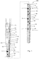
- Fig. 1 shows a layout of a well completion comprising a downhole detection system 100 for monitoring the expansion of one or more annular barriers 1 and thus for verifying that the annular barriers have been expanded sufficiently to provide a substantially tight barrier.
- the specific layout is shown for exemplary purposes and serves only to explain the concept of the invention.
- the downhole detection system 100 may thus be used in any other type of well completion having a different layout, such as more or fewer annular barriers, etc.
- the shown well completion comprises, starting from the top, an intermediate casing 70 provided with two annular barriers 71 for ensuring the pressure integrity of the well and forming part of the primary barrier of the well.
- These annular barriers 71 are expanded in an annulus 2 between the intermediate casing 70 and an inside wall 4 of a borehole 5.
- annular barrier 80 provides a sealing relationship between the intermediate casing 70 and the well tubular structure 3.
- the well tubular structure 3 extends from the intermediate casing 70 down into the well.
- the well tubular structure 3 comprises a plurality of annular barriers 1 adapted to be expanded in the annulus 2 between the well tubular structure 3 and the inside wall 4 of the borehole 5.
- each of the annular barriers 1 comprises a tubular part 6 which has been mounted as part of the well tubular structure 3, e.g. by means of a threaded connection 19.
- the annular barrier 1 comprises an expandable part 7, such as an expandable sleeve, surrounding the tubular part 6, having an outer face 8 which, in an expanded condition of the annular barrier 1, abuts the inside wall 4 of the borehole 5.
- the expandable sleeve is preferably made of metal.
- Each end 9, 10 of the expandable sleeve 7 is fastened to the tubular part 6 by means of a connection part 12.
- the expandable sleeve 7 surrounds the tubular part 6, forming an annular barrier space 13 therebetween ( Fig. 5 ).
- An aperture 11 is arranged in the tubular part 6 through which fluid is let into the space 13 to expand the sleeve 7. As shown in Fig.
- the well tubular structure 3 further comprises a plurality of valve sections 50 for letting hydrocarbon-containing fluid into an inner space 31 of the well tubular structure 3.
- the valve section 50 contains inflow control valves 51 and a fracturing opening or fracturing valve 52.
- a screen 54 may be arranged opposite the valves in a recess on the outer face of the well tubular structure 3.
- a plurality of sliding or rotational sleeves 53 is arranged to close off the valve while the well tubular structure 3 is being pressurised.
- the well tubular structure 3 may be a production casing or injection casing and/or comprise a multitude of other functional elements such as sliding sleeves, screens, gravel packs, etc.
- a lateral cavity in the form of a side pocket 32 is provided in the upper section of the well tubular structure 3, a lateral cavity in the form of a side pocket 32 is provided.
- the side pocket 32 is provided in a side pocket mandrel 33 mounted as part of the well tubular structure 3, but may alternatively be integrated in the well tubular structure.
- the downhole detection system 100 comprises one or more detection devices 20, also shown in Figs. 2 and 6a-d , arranged in connection with the annular barriers 1, such as in the annular barrier 1 or on the outer face of the annular barrier.
- the detection devices 20 detect a condition of the expandable sleeve 7 and generate a signal and/or data representative thereof which is sent via wiring 66 to a data collection unit 60 provided in the side pocket 32 ( Fig. 2 ).
- the data collection unit 60 is releasably connected to the wiring 66, and thus the detection devices 20, via an electrical connection means 65 provided in the side pocket 32.
- signals from multiple detection devices 20 may be transmitted via wiring 66 to the same data collection unit 60 and recorded.
- the wiring 66 extends in the annulus 2 along the outer surface of the well tubular structure 3. Wiring connected to the detection devices 20 arranged at positions below the uppermost annular barrier 1 extends through the annular barrier space 13 of the annular barriers 1 provided between the respective detection devices and the data collection unit 60. The wiring 66 thus extends through the connection part 12 and/or the expandable sleeve 7. Some type of connector may be provided in the connection part 12 or the expandable sleeve 7, whereby wiring connected to opposite sides of the connection part or expandable sleeve is electrically connected. In an alternative configuration, the wiring 66 may extend inside the well tubular structure 3, or it may be embedded in the wall of the well tubular structure or in grooves in the outer face of the well tubular structure.
- the downhole detection system 100 does not require wiring extending to the surface or the wellhead for connecting the downhole detection system to a recording means.
- the downhole detection system 100 may thus be operated as a downhole detection system provided in the well without contact to the surface.
- the data collection unit 60 is either retrieved from the side pocket 32 and brought to the surface for data retrieval, or data is retrieved from the data collection unit 60 downhole while being arranged in the side pocket 32, as will be further described below.
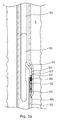
- the data collection unit 60 comprises a storage means 61 for storing the information received from the detection devices 20, a power module 62 for providing power to the data collection unit, and control electronics 63 for controlling the recording of data, such as a processor for processing the signals or data received.
- the processor may process the signal and data before recording it or transferring it to another unit.
- the power module 62 and/or control electronics 63 may be comprised in the stationary part of the downhole detection system 100 which is not retrievable from the well.
- One end of the data collection unit 60 is provided with an interface adapted to be connected to the electrical connection means 65.
- the opposite end comprises a fishing neck 64 for latching onto a tool for retrieving the data collection unit 60 in the side pocket 32.
- a tool is known to the skilled person and may be a kickover tool, as shown in Fig. 3a .
- the kickover tool 90 may be connected to a downhole tractor 95 or stroker for displacing the kickover tool in the well during setting or retrieval of the data collection unit 60.
- the kickover tool 90 comprises a latching arm 92 controlled by a kickover mechanism 91. To retrieve the data collection unit 60, the latching arm 92 is extended from the tool body and into the side pocket 32 by a kickover mechanism 91.
- the latching arm 92 comprises a mechanism known to the skilled person for latching onto the fishing neck 64.
- a downhole tool comprising a kickover tool 90 or any other suitable tool is lowered into the well.
- the kickover tool 90 latches onto the data collection unit 60, the unit is retrieved from the side pocket 32.
- the data collection unit 60 may be replaced with another similar data collection unit or alternatively a plug (not shown) to seal off the electrical connection means 65.
- signals and/or data from the detection devices 20 may be recorded by a stationary data collection unit permanently connected to the wiring 66 and the detection devices 20.
- data is retrieved from the downhole detection system 100 by transferring the data downhole directly to a tool lowered into the well.
- the transferring may take place by using an electrical connection means 65 for connecting the tool and the data collection unit 60, such as a plug and socket, by wireless data transmission, by an inductive coupling or by any other means known to the skilled person.
- Data may be transmitted wirelessly from the data collection unit 60 to the tool lowered into the well by an acoustic link, utilising the borehole or production fluid as the transmission medium.
- the data transfer may be bi-directional using frequencies dependent on the amount of data to be transferred.
- data stored in the storage means 61 may be provided to a transceiver for modulation to a radio frequency signal, whereupon the signal is transmitted via an antenna in the data collection unit to an antenna and a transceiver of the tool lowered into the well.
- modulation formats known to the skilled person may be utilised, and known communication protocols may be implemented.
- the modulation format and protocols may be similar to, or a modified version of, the IEEE 802.11 standard.
- data may be transmitted wirelessly using Bluetooth technology or an electromagnetic short-hop link.
- the downhole detection system 100 may require periodic recharging.
- Recharging may be done by the tool for transferring data or by another tool, e.g. by connecting the tool to the data collection unit 60 using electrical connection means 65 or by means of an inductive coupling.
- the power module 62 may be sufficient to power the system, and the data collection unit 60 may be replaced to recharge the system.
- the data collection unit 60 collects data when the annular barriers 1 are expanded during completion of the well, and the data collection unit therefore only requires a small battery. However, some of the annular barriers 1 may not have been expanded upon completing of the well, but may remain unexpanded and ready for use when a production zone needs to be sealed off and a new production zone established elsewhere. In this event, the data collection unit 60 requires a longer lasting battery or needs to be recharged immediately before expanding some of the remaining unexpanded annular barriers 1.
- the detection system 100 is easily fitted into existing qualified designs of known side pockets as the data collecting unit is easily retrofitted into side pockets already commercially available in the market.
- the side pocket 32 can be reused for inserting a gas lift valve later on when gas lift is required.
- the electrical connection means 65 is arranged in an opening in the side pocket 32 communicating with the annulus 2.
- the gas lift valve thus communicates with the annulus 2 through the same opening.
- the side pocket 32 may alternatively be integrated in the tubular part 6 of the annular barrier 1.
- Individual data collection units 60 may thus be assigned to each of the annular barriers, or the same data collection unit may be used to record data from a group of multiple annular barriers.
- the downhole detection system may be comprised in a downhole system for monitoring the expansion of one or more annular barriers.
- the downhole system comprises a well tubular structure 3 extending from the intermediate casing 70 down into the well.
- the well tubular structure 3 comprises a lateral cavity in the form of a side pocket 32 and a plurality of annular barriers adapted to be expanded in the annulus 2 between the well tubular structure 3 and the inside wall 4 of the borehole 5.
- the well tubular structure may further comprise a plurality of valve sections 50, a screen 54, a plurality of sliding or rotational sleeves 53 and other functional elements as described above.
- the side pocket 32 is provided in the well tubular structure 3 below the primary barrier of the well.
- the data collection unit of the downhole detection system is arranged in the side pocket and the detection decises may be arranged in association with the annular barriers or in other positions along the well tubular structure.
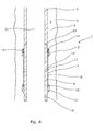
- Fig. 4 shows an annular barrier 1 with the expandable sleeve 7 in an unexpanded position.
- the well tubular structure 3 When expanding the expandable sleeve 7, the well tubular structure 3 is pressurised from the top of the well, and pressurised fluid is forced into the annular barrier space 13, seen in Fig. 5 , to expand the expandable sleeve 7.
- One or both connection parts 12 may be sliding in relation to the tubular part 6, and the other may be fixedly connected with the tubular part 6. In some annular barriers, both connection parts are fixedly connected to the tubular part.
- the sliding connection part 12 is provided with sealing elements 121 creating a seal between the connection part and the tubular structure 3.
- the annular barrier 1 comprises a valve, such as a shut-off valve 14, arranged in the aperture 11.
- the shut-off valve has an open and a closed position. When in the open position, fluid is let into the annular barrier space 13, shown in Fig. 5 , and when in the closed position, the fluid can no longer pass through the valve 14 into the annular barrier space 13.
- the aperture 11 of the tubular part 6 of the annular barrier 1 can be closed when the expandable sleeve 7 has been expanded into a contact position, as shown in Fig. 5 .
- the annular barrier 1 is shown in an activated state with the expandable sleeve 7 in an expanded position.
- the annular barrier 1 comprises a detection device 20 (not shown in Fig. 5 ) monitoring the expansion process.
- the detection device 20 may be adapted to activate the shut-off valve 14 to bring the shut-off valve 14 from the open position to the closed position when detecting that the expandable sleeve 7 has been expanded into a contact position.
- the detection device 20 may comprise a movement sensor 21 for detecting the movement of the sliding connection part 12 or the movement of the expandable sleeve 7.
- the movement sensor 21 detects a movement of the sliding connection part 12 which initiates the detection of a subsequent stop of the movement of the sleeve 7.
- a subsequent stop may indicate that a contact position is reached, in which contact between the outer face 8 of the expandable sleeve 7 and the inner wall 4 of the borehole has been established. In the contact position, the expandable sleeve 7 is prevented from expanding further radially, and thus, the movement of the sliding connection part 12 and the sleeve 7 stops.
- the movement sensor 21 may be a linear potentiometer 34 measuring the position of the sliding connection part 12 in the longitudinal direction along the tubular part 6.
- the linear potentiometer 34 comprises a resistive element 22 and a wiper device 23 displaceable in the longitudinal direction of the resistive element 22.
- the linear potentiometer 34 may be a linear membrane potentiometer of the kind available from the company Spectra Symbols.
- the wiper device 23 is provided on the slidable connection parts 12 being slidable in relation to the tubular part 6. The wiper device 23 abuts the resistive element 22, and by measuring the electrical output, e.g. voltage, from the resistive element 22, it is possible to determine the exact position of the wiper device 23 along the resistive element 22.
- the movement sensor 21 may alternatively be a distance sensor 24 measuring the distance between the slidable connection part 12 and a predetermined position 33 along the tubular part 6.
- the distance sensor 24 may incorporate a laser or any other means known to the skilled person suitable for measuring the distance between the slidable connection part 12 and the predetermined position 33. By continuously measuring the distance, it is possible to determine the position of the slidable connection part and to determine whether the connection part 12 is moving.
- the movement sensor 21 may also be a variable reluctance sensor, such as an inductive magnetic sensor 26, for measuring the position of the slidable connection part 12 in the longitudinal direction along the tubular part 6.
- the inductive magnetic sensor detects a plurality of magnetic elements 25 incorporated in the outer surface 81 of the tubular part 6.
- the frequency of detection of the magnetic element may be monitored.
- the number of magnetic elements may be detected to determine the position of the connection element.
- the movement sensor 21 may also comprise a tracking wheel arranged on the slidable connection part 12 and driving on the outer surface 81 of the tubular part 6. By detecting rotation of the tracking wheel, it is possible to determine whether the slidable connection part 12 is moving. The number of revolutions may also be used to determine the position of the slidable connection part 12.
- the movement sensor 21 continuously detects whether the slidable connection part 12 is moving, and it possibly also records the position in the longitudinal direction to determine the total displacement of the slidable connection part 12. Thus, the movement sensor 21 may be used to determine when the slidable connection part 12 has stopped moving. Output from the movement sensor 21 is used by the detection device 20 to determine when the expandable sleeve 7 has been expanded into a contact position and the shut-off valve 14 should be activated to block the flow of fluid into the space 13.
- the detection device 20 comprises an expansion sensor 29 for detecting a material expansion of the expandable sleeve 7.
- the expansion sensor 29 may comprise a strain gauge 30, as shown in Figs. 6a-c , or any other means suitable for measuring material expansion, provided at an outer face 8 of the expandable sleeve 7.
- the expansion sensor 29, such as the strain gauge 30, may be wirely connected with the data collection unit 60 where the wires extend on the outside of the annular barrier.
- the detection device 20 comprises both a movement sensor 21 and an expansion sensor 29 according to the above.
- the annular barrier 1 comprises one or more contact pressure sensors 27 arranged at the outer face 8 of the expandable sleeve 7.
- the pressure sensors 27 measure the contact pressure between the outer surface 8 of the expandable sleeve 7 and the inner wall 4 of the borehole 5 when the annular barrier 1 is expanded downhole, as shown in Figs. 1 and 5 .
- the detection device 20 may also comprise a distance sensor 28 to measure an inner diameter 36 of the expanded sleeve 7.
- a fluid pressure sensor 35 may be provided to measure the pressure inside the space 13.
- the detection device 20 may rely on one or more detected parameters, such as the movement of the slidable connection part 12, the material expansion of the expandable sleeve 7, the inner diameter 36 of the expanded sleeve 7 and/or the contact pressure or pressure inside the expandable sleeve to determine when the expandable sleeve has been expanded into a contact position.
- the detection device may also comprise sensors 37 for detecting conditions in the annulus 2 outside the annular barrier space 13.
- the sensors 37 may detect flow conditions, temperature, pressure, etc. to determine whether the annular barrier 1 provides the necessary sealing effect between the well tubular structure 3 and the formation.
- the detection device 20 detects when the sliding connection part stops, i.e. when the contact position is reached and/or when the material of the expandable sleeve 7 is no longer expanding because a contact position has been reached.
- the detection device 20 may determine that the expandable sleeve 7 has been sufficiently expanded to provide a sufficient contact between the outer face 8 of the expandable sleeve 7 and the inner wall 4 of the borehole 5, and thus into the contact position.
- the detection device 20 may also detect the pressure in the annular barrier space 13 and await a certain increase in the pressure before determining that the expandable sleeve 7 has been sufficiently expanded.
- the detection device 20 may cause the shut-off valve 14 to close to prevent further pressure being built up inside the space 13 as the pressure in the well is increased to expand other annular barriers 1 requiring a higher expansion pressure.
- the shut-off valve 14 is a solenoid valve which is closed by discontinuing the power required to keep the valve open.
- the shut-off valve 14 is a solenoid valve which is closed by discontinuing the power required to keep the valve open.
- the solenoid valve is discontinued, whereby the valve 14 closes and the space 13 is sealed. If, for some reason, it is required that the shut-off valve is reopened, e.g. to equalise the pressure between the borehole 5 and the space 13 inside the expanded sleeve 7, this may be done by resuming the supply of power to the solenoid valve. Equalisation of the pressure may be required in connection with injection, stimulation or fracture operations.
- the detection device 20 may further comprise a timer for closing the shut-off valve 14 after a predetermined period of time subsequent to the detection of the expandable sleeve 7 being in the contact position in which the sleeve and the sliding connection part are prevented from further movement.
- a timer for closing the shut-off valve 14 after a predetermined period of time subsequent to the detection of the expandable sleeve 7 being in the contact position in which the sleeve and the sliding connection part are prevented from further movement.
- the detection device 20 may further comprise a seismic sensor or another kind of acoustic sensor for detection of the sound at the aperture 11 in order to detect any sound changes during expansion. Fluid flowing into the space 13 makes a certain sound, and when the contact position is reached and the expansion process makes an intermediate stop before continuing and cracking the formation undesirably, the fluid is no longer flowing into the space 13, and the sound is therefore decreased accordingly, indicating that the contact position is reached.
- the detection devices 20 detecting a condition of an expandable sleeve generate signals or data representative of the condition, e.g.
- the data collection unit 60 receives data from a multitude of detection devices 20 monitoring the condition of several annular barriers 1, and data from multiple detection devices may thus be retrieved at a single location in the well. When the well has been completed and the annular barriers activated, the data collection unit 60 may be retrieved to the surface to establish the condition of the annular barriers 1.
- the downhole detection system described above may be used in a method comprising the steps of mounting a data collection unit in a side pocket of a well tubular structure, e.g. by using a kickover tool as described above.
- the data collection device is arranged in the side pocket 32 and connected to the electrical connection means 65, electrical communication is established between the detecting devices arranged in one or more unexpanded annular barriers and the data collection unit 60 through wiring 66 on the outside of the well tubular structure 3.
- the data collection unit 60 may be arranged in the side pocket 32 before or after the well tubular structure 3 is installed in the well.
- the well tubular structure 3 is pressurised from within to expand the annular barriers 1.
- the condition of the expandable part of the annular barrier 1 is detected, and data of the condition is collected in the data collection unit 60.
- the collected data may subsequently be retrieved in a number of different ways, as described above.
- the data collection unit 60 may also be retrieved from the well and/or be replaced. If necessary, the data collection unit 60 and the downhole detection system 100 may be recharged as described above.
- it is determined whether the annular barrier 1 has been expanded properly This may be done by comparing measurements to predetermined threshold values, previously recorded data, statistical models, etc.
- contact position is meant the position of the expanded sleeve in which a contact between the outer face 8 of the expandable sleeve 7 and the inner wall 4 of the borehole or another surrounding casing is reached so that the annular barrier provides an isolation of one part of the annulus from another part of the annulus.
- fluid or well fluid any kind of fluid that may be present in oil or gas wells downhole, such as natural gas, oil, oil mud, crude oil, water, etc.
- gas is meant any kind of gas composition present in a well, completion, or open hole
- oil is meant any kind of oil composition, such as crude oil, an oil-containing fluid, etc.
- Gas, oil, and water fluids may thus all comprise other elements or substances than gas, oil, and/or water, respectively.
- a casing any kind of pipe, tubing, tubular, liner, string etc. used downhole in relation to oil or natural gas production.
- a downhole tractor can be used to push the tools all the way into position in the well.
- a downhole tractor is any kind of driving tool capable of pushing or pulling tools in a well downhole, such as a Well Tractor®.
Landscapes
- Life Sciences & Earth Sciences (AREA)
- Engineering & Computer Science (AREA)
- Geology (AREA)
- Mining & Mineral Resources (AREA)
- Physics & Mathematics (AREA)
- Environmental & Geological Engineering (AREA)
- Fluid Mechanics (AREA)
- General Life Sciences & Earth Sciences (AREA)
- Geochemistry & Mineralogy (AREA)
- Geophysics (AREA)
- Geophysics And Detection Of Objects (AREA)
Abstract
The present invention relates to a downhole detection system for monitoring the expansion of one or more annular barriers. The downhole detection system (100) comprises a plurality of detection devices (20) adapted to be provided in connection with one or more annular barriers (1) for detecting a condition of expansion of the annular barrier in an annulus (2) between a well tubular structure (3) and an inside wall (4) of a borehole (5), and for generating signals or data representative thereof. The detection device(s) is/are connected via wiring (66) to an electrical connection means (65) adapted to be arranged in a side pocket (32) provided in the well tubular structure. Furthermore, the downhole detection system comprises a data collection unit (60) adapted to be left in the side pocket and to be connected to the plurality of downhole detection devices via the electrical connection means whereby signals from the plurality of detection devices are recorded by the data collection unit.
Description
- The present invention relates to a downhole detection system for monitoring the expansion of one or more annular barriers.
- To complete a well for production of hydro carbons, notably oil and gas, a number of casings of varying functionality are generally lowered into the borehole and held in place by injecting cement into an annular space between the casing and the borehole wall. The well is provided with a wellhead through which a production casing is lowered down to the underground zone or reservoir.
- Communicating between surface installations and downhole devices such as sensors, transmitters, receivers, tools, etc. downhole is a cumbersome task which is often accomplished by means of one or several transmission cables or wiring. The cables or wiring run from the downhole devices up to the surface on the outside of the casing and may be embedded in the cement used to complete the well. This kind of linkage with wiring has drawbacks. The wiring has to be run through the wellhead, which may require installation of a wellhead provided with special connectors with sealed terminals or possibly modification of an existing wellhead. Furthermore, cementing of the casing may be difficult. In fact, the casing may sometimes have to be moved or rotated around its own axis so as to better distribute the cement injected. This may result in the wiring being damaged and communication with some of the downhole devices installed in the well being defective. Furthermore, the presence of wiring or cables in the annulus may reduce the sealing integrity of the primary barrier of the well and lead to a leaking well with e.g. oil or gas effluents escaping from the well into the surrounding sea. The primary barrier of the well may comprise a combination of packers or annular barriers and casing cemented in place to provide the necessary sealing between the casing and the formation.
- It is an object of the present invention to wholly or partly overcome the above disadvantages and drawbacks of the prior art. More specifically, it is an object to provide a downhole detection system for monitoring the expansion of one or more annular barriers downhole.
- The above objects, together with numerous other objects, advantages, and features, which will become evident from the below description, are accomplished by a solution in accordance with the present invention by a downhole detection system for monitoring the expansion of one or more annular barriers, comprising:
- a plurality of detection devices adapted to be provided in connection with one or more annular barriers for detecting a condition of expansion of the annular barrier in an annulus between a well tubular structure and an inside wall of a borehole, and for generating signals or data representative thereof,
- the detection device(s) being connected via wiring to an electrical connection means adapted to be arranged in a side pocket provided in the well tubular structure, and
- a data collection unit adapted to be left in the side pocket and to be connected to the plurality of downhole detection devices via the electrical connection means whereby signals from the plurality of detection devices are recorded by the data collection unit.
- By using a common data collection unit for recording signals from the plurality of detection devices monitoring the condition of the one or more annular barriers, e.g. if the expandable sleeve has been expanded sufficiently for creating an annular barrier in the well, data from multiple detection devices may be retrieved at a single location in the well. When the well has been completed and the annular barriers activated, the data collection unit may be retrieved to the surface to establish the condition of the annular barriers. The downhole system may thus e.g. be used for verifying that the annular barriers have been sufficiently inflated and/or for providing a seal between the well tubular structure and the inside wall of a borehole or another tubular structure. As the downhole detection system does not require wiring extending to the surface, the system avoids the drawbacks associated with wiring extending through the wellhead, wiring extending in the annulus outside the casing or the risk of cables being damaged during completion of the well.
- In an embodiment, the data collection unit may be adapted to be left in the side pocket and subsequently retrieved if necessary.
- Furthermore, the detection device may detect the condition of an expandable part of the annular barrier.
- Moreover, the detection device may be adapted to detect when the expandable part has been expanded into a contact position.
- In addition, the data collection unit may be retrievable from the side pocket.
- By having a retrievable data collection unit, the downhole detection system may operate autonomously while the well is completed and the annular barriers activated by supplying fluid through the well tubular structure and pressurising the tubular structure. Subsequently, when the condition of the well, especially the sealing integrity of the annular barriers, needs to be verified, the data collection unit may be retrieved from the well. The downhole detection system thus does not require neither a permanent nor a temporary data cabled or wireless communication linkage to the surface.
- In an embodiment of the invention, the multiple detection devices of multiple annular barriers may be connected to one common data collection unit.
- Furthermore, the wiring may extend along an outer surface of the well tubular structure and/or the tubular part.
- Moreover, the wiring may extend through an annular barrier space between the tubular part and the expandable part.
- Additionally, the wiring may extend through an inner space of the well tubular structure and/or the tubular part.
- In an embodiment, the data collection unit may be adapted to be arranged in a side pocket provided in an upper section of the well tubular structure overlapping with an intermediate casing, but below a barrier arranged between the well tubular structure and the surrounding intermediate structure.
- Moreover, the data collection unit may be arranged in a side pocket provided in an upper part of the well tubular structure or production casing below an annular barrier adapted to be expanded in an annulus between the well tubular structure or production casing and the inside wall of the intermediate casing.
- In addition, the data collection unit may be adapted to be arranged in a side pocket provided above the one or more annular barriers to be expanded.
- Furthermore, the data collection unit may comprise a storage means for storing the information received from the detection devices.
- Additionally, the data collection unit may comprise control electronics for controlling the downhole detection system.
- The data collection unit may further comprise a power module for powering the collection unit.
- The power module may be a battery.
- In an embodiment, the detection device may comprise a movement sensor for detecting movement of a sliding connection part and when the sliding connection part has stopped.
- Furthermore, the movement sensor may be a magnet sensor, an accelerometer, an infrared sensor, a variable reluctance sensor or an inductive magnetic sensor for detecting movement of the sliding connection part.
- The magnet sensor or inductive magnet sensor may sense a plurality of magnets incorporated in the outer surface of the tubular part.
- Moreover, the movement sensor may comprise a tracking wheel driving on the outer surface of the tubular part, thereby detecting movement of the sliding connection part.
- In one embodiment of the invention, the detection device may comprise an expansion sensor for detecting a material expansion of the expandable part and when the material expansion of the expandable part has stopped.
- Moreover, the expansion sensor may comprise a strain gauge for detecting expansion of the material of the expandable part.
- Additionally, the detection device may comprises a contact pressure sensor provided at the outer surface of the expandable part, the pressure sensor being adapted to measure a contact force between the outer surface of the expandable part and an inner wall of the borehole.
- Furthermore, the detection device may comprise a fluid pressure sensor for measuring the fluid pressure inside the annular barrier.
- In addition, the detection device further comprises a distance sensor for measuring a change in a maximum inner diameter of the expandable part.
- Furthermore, the sensor may be an accelerometer or an infrared sensor for detecting fluid movement between the outer face of the expandable sleeve and the formation. The purpose of this is to confirm that the annular barrier has created a seal against the borehole wall.
- The sensors may be arranged on the outer face of the expandable sleeve.
- In an embodiment, each end of the expandable sleeve is fastened to the tubular part by means of a connection part, where one of the connection parts is a sliding connection part sliding in relation to the tubular part when the expandable part, such as a sleeve, is expanded.
- The invention furthermore relates to a completion method for detecting sufficient expansion of annular barriers when completing a well, comprising the steps of:
- mounting a data collection unit in a well tubular structure,
- connecting detecting devices connected with at least one unexpanded annular barrier of the well tubular structure with the data collection unit through wiring on the outside of the well tubular structure,
- installing the well tubular structure in a well,
- pressurising the well tubular structure from within and expanding the annular barrier,
- detecting at least one condition of an expandable part of the annular barrier, and
- collecting data regarding the condition of the at least one expandable part of the annular barrier in the data collection unit.
- Further, the step of mounting the data collection unit in the well tubular structure is performed by mounting the data collection unit in a side pocket of a well tubular structure.
- The completion method further comprises the step of determining whether the annular barrier is properly expanded in a processor.
- In addition, the completion method comprises the step of retrieving the data collection unit.
- Moreover, the completion method comprises the step of transferring data from the data collection unit to a submergible tool.
- Additionally, data is transferred wirelessly from the data collection unit to the tool lowered into the well.
- In one embodiment, the data is transmitted wirelessly from the data collection unit to the tool lowered into the well by acoustic link, utilising the borehole or production fluid as the transmission medium.
- Furthermore, the completion method comprises the step of recharging the data collection unit while being in the side pocket.
- Additionally, the completion method comprises the step of replacing the data collection unit by means of a kickover tool.
- Furthermore, the completion method comprises the step of removing the connection means from an opening in the side pocket.
- Finally, the completion method comprises the step of inserting a gas lift valve in the opening of the side pocket.
- The invention moreover relates to a downhole system for monitoring the expansion of one or more annular barriers, comprising:
- a well tubular structure comprising a side pocket, and
- one or more annular barriers for mounting as part of the well tubular structure, the annular barrier(s) being adapted to be expanded in an annulus between the well tubular structure and an inside wall of a borehole and comprising:
- a tubular part having a longitudinal extension, and
- an expandable part surrounding the tubular part,
- a downhole detection system, comprising:
- one or more detection devices provided in connection with the annular barrier(s) for detecting a condition of the expandable part and generating signals representative thereof, the detection device(s) being connected via wiring to an electrical connection means arranged in the side pocket, and
- a data collection unit for being connected to the downhole detection system via the electrical connection means is provided in the side pocket whereby signals from the detection devices may be recorded by the data collection unit.
- In an embodiment, the expandable part may be an expandable sleeve surrounding a tubular part of the annular barrier.
- Furthermore, the data collection unit may be adapted to be left in the side pocket.
- Additionally, the data collection unit may be arranged in a side pocket provided in an upper section of the well tubular structure overlapping with the intermediate casing.
- The downhole system further comprises the well tubular structure having the side pocket and at least one annular barrier.
- Finally, the downhole system further comprises an intermediate casing and a primary barrier arranged between the intermediate casing and the well tubular structure.
- The invention and its many advantages will be described in more detail below with reference to the accompanying schematic drawings, which for the purpose of illustration show some non-limiting embodiments and in which
-
Fig. 1 shows a layout of a well comprising a downhole system for detecting the expansion of annular barriers, -
Fig. 2 shows an annular barrier comprising a data collection unit, -
Fig. 3a shows a kickover tool for setting and retrieving the data collection unit, -
Fig. 3b shows another configuration of a downhole detection system, -
Fig. 4 shows an annular barrier being part of the well tubular structure in an unexpanded condition, -
Fig. 5 shows the annular barrier ofFig. 4 in an expanded condition, -
Figs. 6a-6d illustrate different annular barriers comprising detection devices for detecting when the expandable sleeve has been expanded into a contact position, and -
Fig. 7 shows a valve section for letting hydrocarbon-containing fluid into the well tubular structure. - All the figures are highly schematic and not necessarily to scale, and they show only those parts which are necessary in order to elucidate the invention, other parts being omitted or merely suggested.
-
Fig. 1 shows a layout of a well completion comprising adownhole detection system 100 for monitoring the expansion of one or moreannular barriers 1 and thus for verifying that the annular barriers have been expanded sufficiently to provide a substantially tight barrier. The specific layout is shown for exemplary purposes and serves only to explain the concept of the invention. Thedownhole detection system 100 may thus be used in any other type of well completion having a different layout, such as more or fewer annular barriers, etc. - The shown well completion comprises, starting from the top, an
intermediate casing 70 provided with twoannular barriers 71 for ensuring the pressure integrity of the well and forming part of the primary barrier of the well. Theseannular barriers 71 are expanded in anannulus 2 between theintermediate casing 70 and aninside wall 4 of aborehole 5. - Inside the
intermediate casing 70, an upper section of a welltubular structure 3 is provided, and anotherannular barrier 80 provides a sealing relationship between theintermediate casing 70 and the welltubular structure 3. The welltubular structure 3 extends from theintermediate casing 70 down into the well. The welltubular structure 3 comprises a plurality ofannular barriers 1 adapted to be expanded in theannulus 2 between the welltubular structure 3 and theinside wall 4 of theborehole 5. As shown inFig. 4 , each of theannular barriers 1 comprises atubular part 6 which has been mounted as part of the welltubular structure 3, e.g. by means of a threadedconnection 19. Theannular barrier 1 comprises anexpandable part 7, such as an expandable sleeve, surrounding thetubular part 6, having anouter face 8 which, in an expanded condition of theannular barrier 1, abuts theinside wall 4 of theborehole 5. The expandable sleeve is preferably made of metal. Eachend expandable sleeve 7 is fastened to thetubular part 6 by means of aconnection part 12. Theexpandable sleeve 7 surrounds thetubular part 6, forming anannular barrier space 13 therebetween (Fig. 5 ). Anaperture 11 is arranged in thetubular part 6 through which fluid is let into thespace 13 to expand thesleeve 7. As shown inFig. 7 , the welltubular structure 3 further comprises a plurality ofvalve sections 50 for letting hydrocarbon-containing fluid into aninner space 31 of the welltubular structure 3. Thevalve section 50 containsinflow control valves 51 and a fracturing opening or fracturingvalve 52. Ascreen 54 may be arranged opposite the valves in a recess on the outer face of the welltubular structure 3. Opposite thevalve 14, a plurality of sliding orrotational sleeves 53 is arranged to close off the valve while the welltubular structure 3 is being pressurised. The welltubular structure 3 may be a production casing or injection casing and/or comprise a multitude of other functional elements such as sliding sleeves, screens, gravel packs, etc. - Returning to
Fig. 1 , in the upper section of the welltubular structure 3, a lateral cavity in the form of aside pocket 32 is provided. Theside pocket 32 is provided in aside pocket mandrel 33 mounted as part of the welltubular structure 3, but may alternatively be integrated in the well tubular structure. - The
downhole detection system 100 comprises one ormore detection devices 20, also shown inFigs. 2 and6a-d , arranged in connection with theannular barriers 1, such as in theannular barrier 1 or on the outer face of the annular barrier. Thedetection devices 20 detect a condition of theexpandable sleeve 7 and generate a signal and/or data representative thereof which is sent viawiring 66 to adata collection unit 60 provided in the side pocket 32 (Fig. 2 ). Thedata collection unit 60 is releasably connected to thewiring 66, and thus thedetection devices 20, via an electrical connection means 65 provided in theside pocket 32. Hereby, signals frommultiple detection devices 20 may be transmitted viawiring 66 to the samedata collection unit 60 and recorded. Thewiring 66 extends in theannulus 2 along the outer surface of the welltubular structure 3. Wiring connected to thedetection devices 20 arranged at positions below the uppermostannular barrier 1 extends through theannular barrier space 13 of theannular barriers 1 provided between the respective detection devices and thedata collection unit 60. Thewiring 66 thus extends through theconnection part 12 and/or theexpandable sleeve 7. Some type of connector may be provided in theconnection part 12 or theexpandable sleeve 7, whereby wiring connected to opposite sides of the connection part or expandable sleeve is electrically connected. In an alternative configuration, thewiring 66 may extend inside the welltubular structure 3, or it may be embedded in the wall of the well tubular structure or in grooves in the outer face of the well tubular structure. - By recording the signals from the
detection devices 20 on thedata collection unit 60, thedownhole detection system 100 does not require wiring extending to the surface or the wellhead for connecting the downhole detection system to a recording means. Thedownhole detection system 100 may thus be operated as a downhole detection system provided in the well without contact to the surface. To acces the recorded data, thedata collection unit 60 is either retrieved from theside pocket 32 and brought to the surface for data retrieval, or data is retrieved from thedata collection unit 60 downhole while being arranged in theside pocket 32, as will be further described below. - As shown in
Fig. 2 , thedata collection unit 60 comprises a storage means 61 for storing the information received from thedetection devices 20, apower module 62 for providing power to the data collection unit, andcontrol electronics 63 for controlling the recording of data, such as a processor for processing the signals or data received. The processor may process the signal and data before recording it or transferring it to another unit. Alternatively, thepower module 62 and/orcontrol electronics 63 may be comprised in the stationary part of thedownhole detection system 100 which is not retrievable from the well. - One end of the
data collection unit 60 is provided with an interface adapted to be connected to the electrical connection means 65. The opposite end comprises afishing neck 64 for latching onto a tool for retrieving thedata collection unit 60 in theside pocket 32. Such a tool is known to the skilled person and may be a kickover tool, as shown inFig. 3a . Thekickover tool 90 may be connected to adownhole tractor 95 or stroker for displacing the kickover tool in the well during setting or retrieval of thedata collection unit 60. Thekickover tool 90 comprises a latchingarm 92 controlled by akickover mechanism 91. To retrieve thedata collection unit 60, the latchingarm 92 is extended from the tool body and into theside pocket 32 by akickover mechanism 91. At adistal end 93, the latchingarm 92 comprises a mechanism known to the skilled person for latching onto thefishing neck 64. When thedata collection unit 60 is to be retrieved to the surface, a downhole tool comprising akickover tool 90 or any other suitable tool is lowered into the well. When thekickover tool 90 latches onto thedata collection unit 60, the unit is retrieved from theside pocket 32. In the same operation, thedata collection unit 60 may be replaced with another similar data collection unit or alternatively a plug (not shown) to seal off the electrical connection means 65. In an alternative configuration, signals and/or data from thedetection devices 20 may be recorded by a stationary data collection unit permanently connected to thewiring 66 and thedetection devices 20. In this configuration, data is retrieved from thedownhole detection system 100 by transferring the data downhole directly to a tool lowered into the well. The transferring may take place by using an electrical connection means 65 for connecting the tool and thedata collection unit 60, such as a plug and socket, by wireless data transmission, by an inductive coupling or by any other means known to the skilled person. Data may be transmitted wirelessly from thedata collection unit 60 to the tool lowered into the well by an acoustic link, utilising the borehole or production fluid as the transmission medium. The data transfer may be bi-directional using frequencies dependent on the amount of data to be transferred. To transfer data from thedata collection unit 60, data stored in the storage means 61 may be provided to a transceiver for modulation to a radio frequency signal, whereupon the signal is transmitted via an antenna in the data collection unit to an antenna and a transceiver of the tool lowered into the well. Various modulation formats known to the skilled person may be utilised, and known communication protocols may be implemented. For example, the modulation format and protocols may be similar to, or a modified version of, the IEEE 802.11 standard. Alternatively, data may be transmitted wirelessly using Bluetooth technology or an electromagnetic short-hop link. In a configuration using a stationary data collection unit, thedownhole detection system 100 may require periodic recharging. Recharging may be done by the tool for transferring data or by another tool, e.g. by connecting the tool to thedata collection unit 60 using electrical connection means 65 or by means of an inductive coupling. When the retrievabledata collection unit 60 is used, thepower module 62 may be sufficient to power the system, and thedata collection unit 60 may be replaced to recharge the system. - The
data collection unit 60 collects data when theannular barriers 1 are expanded during completion of the well, and the data collection unit therefore only requires a small battery. However, some of theannular barriers 1 may not have been expanded upon completing of the well, but may remain unexpanded and ready for use when a production zone needs to be sealed off and a new production zone established elsewhere. In this event, thedata collection unit 60 requires a longer lasting battery or needs to be recharged immediately before expanding some of the remaining unexpandedannular barriers 1. - As shown in
Fig. 3b , thedetection system 100 is easily fitted into existing qualified designs of known side pockets as the data collecting unit is easily retrofitted into side pockets already commercially available in the market. And when used for expanding theannular barriers 1, theside pocket 32 can be reused for inserting a gas lift valve later on when gas lift is required. In this configuration, the electrical connection means 65, is arranged in an opening in theside pocket 32 communicating with theannulus 2. The gas lift valve thus communicates with theannulus 2 through the same opening. Furthermore, as illustrated inFig. 2 , theside pocket 32 may alternatively be integrated in thetubular part 6 of theannular barrier 1. Individualdata collection units 60 may thus be assigned to each of the annular barriers, or the same data collection unit may be used to record data from a group of multiple annular barriers. - Moreover, the downhole detection system may be comprised in a downhole system for monitoring the expansion of one or more annular barriers. The downhole system comprises a well
tubular structure 3 extending from theintermediate casing 70 down into the well. The welltubular structure 3 comprises a lateral cavity in the form of aside pocket 32 and a plurality of annular barriers adapted to be expanded in theannulus 2 between the welltubular structure 3 and theinside wall 4 of theborehole 5. The well tubular structure may further comprise a plurality ofvalve sections 50, ascreen 54, a plurality of sliding orrotational sleeves 53 and other functional elements as described above. In one configuration, theside pocket 32 is provided in the welltubular structure 3 below the primary barrier of the well. The data collection unit of the downhole detection system is arranged in the side pocket and the detection decises may be arranged in association with the annular barriers or in other positions along the well tubular structure. -
Fig. 4 shows anannular barrier 1 with theexpandable sleeve 7 in an unexpanded position. When expanding theexpandable sleeve 7, the welltubular structure 3 is pressurised from the top of the well, and pressurised fluid is forced into theannular barrier space 13, seen inFig. 5 , to expand theexpandable sleeve 7. One or bothconnection parts 12 may be sliding in relation to thetubular part 6, and the other may be fixedly connected with thetubular part 6. In some annular barriers, both connection parts are fixedly connected to the tubular part. The slidingconnection part 12 is provided with sealingelements 121 creating a seal between the connection part and thetubular structure 3. Theannular barrier 1 comprises a valve, such as a shut-offvalve 14, arranged in theaperture 11. The shut-off valve has an open and a closed position. When in the open position, fluid is let into theannular barrier space 13, shown inFig. 5 , and when in the closed position, the fluid can no longer pass through thevalve 14 into theannular barrier space 13. By having a shut-offvalve 14, theaperture 11 of thetubular part 6 of theannular barrier 1 can be closed when theexpandable sleeve 7 has been expanded into a contact position, as shown inFig. 5 . - In
Fig. 5 , theannular barrier 1 is shown in an activated state with theexpandable sleeve 7 in an expanded position. To be able to monitor the expansion process and detect when theexpandable sleeve 7 has been expanded into a contact position, as shown inFig. 5 , theannular barrier 1 comprises a detection device 20 (not shown inFig. 5 ) monitoring the expansion process. Thedetection device 20 may be adapted to activate the shut-offvalve 14 to bring the shut-offvalve 14 from the open position to the closed position when detecting that theexpandable sleeve 7 has been expanded into a contact position. - Many configurations of the
detection device 20 may be envisaged without departing from the scope of the invention. As shown inFig. 6a , thedetection device 20 may comprise amovement sensor 21 for detecting the movement of the slidingconnection part 12 or the movement of theexpandable sleeve 7. Themovement sensor 21 detects a movement of the slidingconnection part 12 which initiates the detection of a subsequent stop of the movement of thesleeve 7. A subsequent stop may indicate that a contact position is reached, in which contact between theouter face 8 of theexpandable sleeve 7 and theinner wall 4 of the borehole has been established. In the contact position, theexpandable sleeve 7 is prevented from expanding further radially, and thus, the movement of the slidingconnection part 12 and thesleeve 7 stops. - As shown in
Fig. 6a , themovement sensor 21 may be alinear potentiometer 34 measuring the position of the slidingconnection part 12 in the longitudinal direction along thetubular part 6. Thelinear potentiometer 34 comprises aresistive element 22 and awiper device 23 displaceable in the longitudinal direction of theresistive element 22. Thelinear potentiometer 34 may be a linear membrane potentiometer of the kind available from the company Spectra Symbols. Thewiper device 23 is provided on theslidable connection parts 12 being slidable in relation to thetubular part 6. Thewiper device 23 abuts theresistive element 22, and by measuring the electrical output, e.g. voltage, from theresistive element 22, it is possible to determine the exact position of thewiper device 23 along theresistive element 22. - As shown in
Fig. 6b , themovement sensor 21 may alternatively be adistance sensor 24 measuring the distance between theslidable connection part 12 and apredetermined position 33 along thetubular part 6. Thedistance sensor 24 may incorporate a laser or any other means known to the skilled person suitable for measuring the distance between theslidable connection part 12 and thepredetermined position 33. By continuously measuring the distance, it is possible to determine the position of the slidable connection part and to determine whether theconnection part 12 is moving. - As shown in
Fig. 6c , themovement sensor 21 may also be a variable reluctance sensor, such as an inductive magnetic sensor 26, for measuring the position of theslidable connection part 12 in the longitudinal direction along thetubular part 6. The inductive magnetic sensor detects a plurality ofmagnetic elements 25 incorporated in theouter surface 81 of thetubular part 6. To detect movement of theslidable connection part 12, the frequency of detection of the magnetic element may be monitored. Alternatively, the number of magnetic elements may be detected to determine the position of the connection element. - The
movement sensor 21 may also comprise a tracking wheel arranged on theslidable connection part 12 and driving on theouter surface 81 of thetubular part 6. By detecting rotation of the tracking wheel, it is possible to determine whether theslidable connection part 12 is moving. The number of revolutions may also be used to determine the position of theslidable connection part 12. - The
movement sensor 21 continuously detects whether theslidable connection part 12 is moving, and it possibly also records the position in the longitudinal direction to determine the total displacement of theslidable connection part 12. Thus, themovement sensor 21 may be used to determine when theslidable connection part 12 has stopped moving. Output from themovement sensor 21 is used by thedetection device 20 to determine when theexpandable sleeve 7 has been expanded into a contact position and the shut-offvalve 14 should be activated to block the flow of fluid into thespace 13. - In another configuration, the
detection device 20 comprises anexpansion sensor 29 for detecting a material expansion of theexpandable sleeve 7. Theexpansion sensor 29 may comprise astrain gauge 30, as shown inFigs. 6a-c , or any other means suitable for measuring material expansion, provided at anouter face 8 of theexpandable sleeve 7. Theexpansion sensor 29, such as thestrain gauge 30, may be wirely connected with thedata collection unit 60 where the wires extend on the outside of the annular barrier. - In a further configuration, the
detection device 20 comprises both amovement sensor 21 and anexpansion sensor 29 according to the above. - Various other sensors capable of determining when the
expandable sleeve 7 has been expanded into a contact position may also be incorporated into thedetection device 20. As shown inFig. 6c , theannular barrier 1 comprises one or morecontact pressure sensors 27 arranged at theouter face 8 of theexpandable sleeve 7. Thepressure sensors 27 measure the contact pressure between theouter surface 8 of theexpandable sleeve 7 and theinner wall 4 of theborehole 5 when theannular barrier 1 is expanded downhole, as shown inFigs. 1 and5 . Thedetection device 20 may also comprise adistance sensor 28 to measure aninner diameter 36 of the expandedsleeve 7. Furthermore, afluid pressure sensor 35 may be provided to measure the pressure inside thespace 13. - The
detection device 20 may rely on one or more detected parameters, such as the movement of theslidable connection part 12, the material expansion of theexpandable sleeve 7, theinner diameter 36 of the expandedsleeve 7 and/or the contact pressure or pressure inside the expandable sleeve to determine when the expandable sleeve has been expanded into a contact position. - The detection device may also comprise
sensors 37 for detecting conditions in theannulus 2 outside theannular barrier space 13. Thesensors 37 may detect flow conditions, temperature, pressure, etc. to determine whether theannular barrier 1 provides the necessary sealing effect between the welltubular structure 3 and the formation. - When the
expandable sleeves 7 are to be expanded by pressurising thetubular structure 3 from within, thedetection device 20 detects when the sliding connection part stops, i.e. when the contact position is reached and/or when the material of theexpandable sleeve 7 is no longer expanding because a contact position has been reached. When the slidingconnection part 12 has stopped and/or when the material of theexpandable sleeve 7 is no longer expanding, thedetection device 20 may determine that theexpandable sleeve 7 has been sufficiently expanded to provide a sufficient contact between theouter face 8 of theexpandable sleeve 7 and theinner wall 4 of theborehole 5, and thus into the contact position. Thedetection device 20 may also detect the pressure in theannular barrier space 13 and await a certain increase in the pressure before determining that theexpandable sleeve 7 has been sufficiently expanded. - When the
detection device 20 determines that theexpandable sleeve 7 has been sufficiently expanded, meaning that the contact position has been reached, thedetection device 20 may cause the shut-offvalve 14 to close to prevent further pressure being built up inside thespace 13 as the pressure in the well is increased to expand otherannular barriers 1 requiring a higher expansion pressure. In one embodiment, the shut-offvalve 14 is a solenoid valve which is closed by discontinuing the power required to keep the valve open. Thus, when theexpandable sleeve 7 has been sufficiently expanded, power to the solenoid valve is discontinued, whereby thevalve 14 closes and thespace 13 is sealed. If, for some reason, it is required that the shut-off valve is reopened, e.g. to equalise the pressure between theborehole 5 and thespace 13 inside the expandedsleeve 7, this may be done by resuming the supply of power to the solenoid valve. Equalisation of the pressure may be required in connection with injection, stimulation or fracture operations. - The
detection device 20 may further comprise a timer for closing the shut-offvalve 14 after a predetermined period of time subsequent to the detection of theexpandable sleeve 7 being in the contact position in which the sleeve and the sliding connection part are prevented from further movement. By having a timer, the closing of the valve may take place at a certain delay in order to ensure that thesleeve 7 is fully expanded and that thevalve 14 is not closed too early. - The
detection device 20 may further comprise a seismic sensor or another kind of acoustic sensor for detection of the sound at theaperture 11 in order to detect any sound changes during expansion. Fluid flowing into thespace 13 makes a certain sound, and when the contact position is reached and the expansion process makes an intermediate stop before continuing and cracking the formation undesirably, the fluid is no longer flowing into thespace 13, and the sound is therefore decreased accordingly, indicating that the contact position is reached. During activation of theannular barriers 1, thedetection devices 20 detecting a condition of an expandable sleeve generate signals or data representative of the condition, e.g. a signal indicative of whether the expandable sleeve has been expanded into a contact position or whether theannular barrier 1 provides a fluid-tight seal between the welltubular structure 3 and theinside wall 4 of theborehole 5. The signal or data is sent via thewiring 66 to thedata collection unit 60 provided in theside pocket 32. As previously stated, in one configuration, thedata collection unit 60 receives data from a multitude ofdetection devices 20 monitoring the condition of severalannular barriers 1, and data from multiple detection devices may thus be retrieved at a single location in the well. When the well has been completed and the annular barriers activated, thedata collection unit 60 may be retrieved to the surface to establish the condition of theannular barriers 1. - In the following, a method for detecting sufficient expansion of
annular barriers 1 upon completion of a well will be described. The downhole detection system described above may be used in a method comprising the steps of mounting a data collection unit in a side pocket of a well tubular structure, e.g. by using a kickover tool as described above. When the data collection device is arranged in theside pocket 32 and connected to the electrical connection means 65, electrical communication is established between the detecting devices arranged in one or more unexpanded annular barriers and thedata collection unit 60 throughwiring 66 on the outside of the welltubular structure 3. Thedata collection unit 60 may be arranged in theside pocket 32 before or after the welltubular structure 3 is installed in the well. Subsequently, the welltubular structure 3 is pressurised from within to expand theannular barriers 1. During expansion, the condition of the expandable part of theannular barrier 1 is detected, and data of the condition is collected in thedata collection unit 60. The collected data may subsequently be retrieved in a number of different ways, as described above. Thedata collection unit 60 may also be retrieved from the well and/or be replaced. If necessary, thedata collection unit 60 and thedownhole detection system 100 may be recharged as described above. Based on the collected data, it is determined whether theannular barrier 1 has been expanded properly. This may be done by comparing measurements to predetermined threshold values, previously recorded data, statistical models, etc. - By contact position is meant the position of the expanded sleeve in which a contact between the
outer face 8 of theexpandable sleeve 7 and theinner wall 4 of the borehole or another surrounding casing is reached so that the annular barrier provides an isolation of one part of the annulus from another part of the annulus. - By fluid or well fluid is meant any kind of fluid that may be present in oil or gas wells downhole, such as natural gas, oil, oil mud, crude oil, water, etc. By gas is meant any kind of gas composition present in a well, completion, or open hole, and by oil is meant any kind of oil composition, such as crude oil, an oil-containing fluid, etc. Gas, oil, and water fluids may thus all comprise other elements or substances than gas, oil, and/or water, respectively.
- By a casing is meant any kind of pipe, tubing, tubular, liner, string etc. used downhole in relation to oil or natural gas production.
- In the event that the tools are not submergible all the way into the casing, a downhole tractor can be used to push the tools all the way into position in the well. A downhole tractor is any kind of driving tool capable of pushing or pulling tools in a well downhole, such as a Well Tractor®.
- Although the invention has been described in the above in connection with preferred embodiments of the invention, it will be evident for a person skilled in the art that several modifications are conceivable without departing from the invention as defined by the following claims.
Claims (16)
- A downhole detection system (100) for monitoring the expansion of one or more annular barriers, comprising:- a plurality of detection devices (20) adapted to be provided in connection with one or more annular barriers (1) for detecting a condition of expansion of the annular barrier in an annulus (2) between a well tubular structure (3) and an inside wall (4) of a borehole (5), and for generating signals or data representative thereof,- the detection device(s) being connected via wiring (66) to an electrical connection means (65) adapted to be arranged in a side pocket (32) provided in the well tubular structure, and- a data collection unit adapted to be left in the side pocket and to be connected to the plurality of downhole detection devices via the electrical connection means whereby signals from the plurality of detection devices are recorded by the data collection unit.
- A downhole system according to claim 1, wherein the detection device (20) is adapted to detect when the expandable part has been expanded into a contact position.
- A downhole system according to claim 1 or 2, wherein the data collection unit is retrievable from the side pocket.
- A downhole system according to any of the preceding claims, wherein the multiple detection devices of multiple annular barriers are connected to one common data collection unit.
- A downhole system according to any of the preceding claims, wherein the wiring extends along an outer surface (81) of the well tubular structure and/or the tubular part.
- A downhole system according to any of the preceding claims, wherein the data collection unit is adapted to be arranged in a side pocket provided in an upper section of the well tubular structure overlapping with an intermediate casing (70), but below a barrier arranged between the well tubular structure and the surrounding intermediate structure.
- A downhole system according to any of the preceding claims, wherein the data collection unit is adapted to be arranged in a side pocket provided above the one or more annular barriers to be expanded.
- A downhole system according to any of the preceding claims, wherein the data collection unit comprises a storage means (61) for storing the information received from the detection devices.
- A downhole system according to any of the preceding claims, wherein the data collection unit further comprises a power module (62) for powering the collection unit.
- A downhole system according to any of the preceding claims, wherein the detection device comprises a movement sensor (21) for detecting movement of a sliding connection part (12) and when the sliding connection part has stopped.
- A downhole system according to claim 10, wherein the movement sensor is a magnet sensor, an accelerometer, an infrared sensor, a variable reluctance sensor or an inductive magnetic sensor (26) for detecting movement of the sliding connection part.
- A downhole system according to any of the preceding claims, wherein the detection device comprises an expansion sensor (29) for detecting a material expansion of the expandable part and when the material expansion of the expandable part has stopped.
- A downhole system according to any of the preceding claims, wherein the detection device comprises a contact pressure sensor (27) provided at the outer surface of the expandable part, the pressure sensor being adapted to measure a contact force between the outer surface of the expandable part and an inner wall (4) of the borehole.
- A downhole system according to any of the preceding claims, wherein the detection device comprises a fluid pressure sensor (35) for measuring the fluid pressure inside the annular barrier.
- A downhole system according to any of the preceding claims, wherein the detection device further comprises a distance sensor (28) for measuring a change in a maximum inner diameter (36) of the expandable part.
- A completion method for detecting sufficient expansion of annular barriers when completing a well, comprising the steps of:- mounting a data collection unit according to any of the claims 1-15 in a well tubular structure,- connecting detecting devices connected with at least one unexpanded annular barrier of the well tubular structure with the data collection unit through wiring on the outside of the well tubular structure,- installing the well tubular structure in a well,- pressurising the well tubular structure from within and expanding the annular barrier,- detecting at least one condition of an expandable part of the annular barrier, and- collecting data regarding the condition of the at least one expandable part of the annular barrier in the data collection unit.
Priority Applications (2)
| Application Number | Priority Date | Filing Date | Title |
|---|---|---|---|
| EP12160999.4A EP2642066A1 (en) | 2012-03-23 | 2012-03-23 | Downhole detection system |
| PCT/EP2013/055771 WO2013139830A2 (en) | 2012-03-23 | 2013-03-20 | Downhole detection system |
Applications Claiming Priority (1)
| Application Number | Priority Date | Filing Date | Title |
|---|---|---|---|
| EP12160999.4A EP2642066A1 (en) | 2012-03-23 | 2012-03-23 | Downhole detection system |
Publications (1)
| Publication Number | Publication Date |
|---|---|
| EP2642066A1 true EP2642066A1 (en) | 2013-09-25 |
Family
ID=47901999
Family Applications (1)
| Application Number | Title | Priority Date | Filing Date |
|---|---|---|---|
| EP12160999.4A Withdrawn EP2642066A1 (en) | 2012-03-23 | 2012-03-23 | Downhole detection system |
Country Status (2)
| Country | Link |
|---|---|
| EP (1) | EP2642066A1 (en) |
| WO (1) | WO2013139830A2 (en) |
Cited By (8)
| Publication number | Priority date | Publication date | Assignee | Title |
|---|---|---|---|---|
| US20160108692A1 (en) * | 2013-12-20 | 2016-04-21 | Halliburton Energy Services, Inc. | Downhole tool with retrievable electronics |
| WO2017089343A1 (en) * | 2015-11-23 | 2017-06-01 | Welltec A/S | Annular barrier completion with inductive system |
| EP3187682A1 (en) * | 2016-01-04 | 2017-07-05 | Welltec A/S | Downhole annular barrier provided with an electrical conductor |
| EP3310991A1 (en) * | 2015-06-16 | 2018-04-25 | Welltec A/S | Redressing method and redressed completion system |
| EP3327246A1 (en) * | 2016-11-25 | 2018-05-30 | Welltec A/S | Annular barrier with expansion verification |
| EP3379025A1 (en) * | 2017-03-21 | 2018-09-26 | Welltec A/S | Downhole completion system |
| WO2019147268A1 (en) * | 2018-01-26 | 2019-08-01 | Halliburton Energy Services, Inc. | Retrievable well assemblies and devices |
| WO2020204874A1 (en) * | 2019-03-29 | 2020-10-08 | Halliburton Energy Services, Inc. | Accessible wellbore devices |
Citations (5)
| Publication number | Priority date | Publication date | Assignee | Title |
|---|---|---|---|---|
| US20040020643A1 (en) * | 2002-07-30 | 2004-02-05 | Thomeer Hubertus V. | Universal downhole tool control apparatus and methods |
| US20100212891A1 (en) * | 2009-02-20 | 2010-08-26 | Halliburton Energy Services, Inc. | Swellable Material Activation and Monitoring in a Subterranean Well |
| US20110061862A1 (en) * | 2009-09-11 | 2011-03-17 | Schlumberger Technology Corporation | Instrumented swellable element |
| WO2011079169A2 (en) * | 2009-12-23 | 2011-06-30 | Schlumberger Canada Limited | Hydraulic deployment of a well isolation mechanism |
| WO2011115805A2 (en) * | 2010-03-15 | 2011-09-22 | Schlumberger Canada Limited | Packer deployed formation sensor |
Family Cites Families (2)
| Publication number | Priority date | Publication date | Assignee | Title |
|---|---|---|---|---|
| US5130705A (en) * | 1990-12-24 | 1992-07-14 | Petroleum Reservoir Data, Inc. | Downhole well data recorder and method |
| US6789621B2 (en) * | 2000-08-03 | 2004-09-14 | Schlumberger Technology Corporation | Intelligent well system and method |
-
2012
- 2012-03-23 EP EP12160999.4A patent/EP2642066A1/en not_active Withdrawn
-
2013
- 2013-03-20 WO PCT/EP2013/055771 patent/WO2013139830A2/en not_active Ceased
Patent Citations (5)
| Publication number | Priority date | Publication date | Assignee | Title |
|---|---|---|---|---|
| US20040020643A1 (en) * | 2002-07-30 | 2004-02-05 | Thomeer Hubertus V. | Universal downhole tool control apparatus and methods |
| US20100212891A1 (en) * | 2009-02-20 | 2010-08-26 | Halliburton Energy Services, Inc. | Swellable Material Activation and Monitoring in a Subterranean Well |
| US20110061862A1 (en) * | 2009-09-11 | 2011-03-17 | Schlumberger Technology Corporation | Instrumented swellable element |
| WO2011079169A2 (en) * | 2009-12-23 | 2011-06-30 | Schlumberger Canada Limited | Hydraulic deployment of a well isolation mechanism |
| WO2011115805A2 (en) * | 2010-03-15 | 2011-09-22 | Schlumberger Canada Limited | Packer deployed formation sensor |
Cited By (28)
| Publication number | Priority date | Publication date | Assignee | Title |
|---|---|---|---|---|
| US20160108692A1 (en) * | 2013-12-20 | 2016-04-21 | Halliburton Energy Services, Inc. | Downhole tool with retrievable electronics |
| US10443332B2 (en) * | 2013-12-20 | 2019-10-15 | Halliburton Energy Services, Inc. | Downhole tool with retrievable electronics |
| EP3310991A1 (en) * | 2015-06-16 | 2018-04-25 | Welltec A/S | Redressing method and redressed completion system |
| CN108350730A (en) * | 2015-11-23 | 2018-07-31 | 韦尔泰克有限公司 | Annular barrier completion system with induction system |
| WO2017089343A1 (en) * | 2015-11-23 | 2017-06-01 | Welltec A/S | Annular barrier completion with inductive system |
| RU2738918C2 (en) * | 2015-11-23 | 2020-12-18 | Веллтек Ойлфилд Солюшнс АГ | Annular barrier for equipping wells with inductive system |
| US10100599B2 (en) | 2015-11-23 | 2018-10-16 | Welltec A/S | Annular barrier completion with inductive system |
| AU2016358614B2 (en) * | 2015-11-23 | 2019-05-16 | Welltec Manufacturing Center Completions ApS | Annular barrier completion with inductive system |
| EP3187682A1 (en) * | 2016-01-04 | 2017-07-05 | Welltec A/S | Downhole annular barrier provided with an electrical conductor |
| EP3327246A1 (en) * | 2016-11-25 | 2018-05-30 | Welltec A/S | Annular barrier with expansion verification |
| WO2018096079A1 (en) * | 2016-11-25 | 2018-05-31 | Welltec A/S | Annular barrier with expansion verification |
| AU2017364219B2 (en) * | 2016-11-25 | 2020-07-30 | Welltec Oilfield Solutions Ag | Annular barrier with expansion verification |
| CN109952412A (en) * | 2016-11-25 | 2019-06-28 | 韦尔泰克油田解决方案股份公司 | Ring Barrier with Inflation Validation |
| US10605039B2 (en) | 2016-11-25 | 2020-03-31 | Welltec Oilfield Solutions Ag | Annular barrier with expansion verification |
| EP3379025A1 (en) * | 2017-03-21 | 2018-09-26 | Welltec A/S | Downhole completion system |
| EP3601732A1 (en) * | 2017-03-21 | 2020-02-05 | Welltec Oilfield Solutions AG | Downhole completion system |
| WO2018172301A1 (en) * | 2017-03-21 | 2018-09-27 | Welltec Oilfield Solutions Ag | Downhole completion system |
| US10774619B2 (en) | 2017-03-21 | 2020-09-15 | Welltec Oilfield Solutions Ag | Downhole completion system |
| CN110382821A (en) * | 2017-03-21 | 2019-10-25 | 韦尔泰克油田解决方案股份公司 | Downhole completion system |
| US20180274336A1 (en) * | 2017-03-21 | 2018-09-27 | Welltec A/S | Downhole completion system |
| GB2581734B (en) * | 2018-01-26 | 2022-07-13 | Halliburton Energy Services Inc | Retrievable well assemblies and devices |
| WO2019147268A1 (en) * | 2018-01-26 | 2019-08-01 | Halliburton Energy Services, Inc. | Retrievable well assemblies and devices |
| GB2581734A (en) * | 2018-01-26 | 2020-08-26 | Halliburton Energy Services Inc | Retrievable well assemblies and devices |
| US11566494B2 (en) | 2018-01-26 | 2023-01-31 | Halliburton Energy Services, Inc. | Retrievable well assemblies and devices |
| WO2020204874A1 (en) * | 2019-03-29 | 2020-10-08 | Halliburton Energy Services, Inc. | Accessible wellbore devices |
| US11286767B2 (en) | 2019-03-29 | 2022-03-29 | Halliburton Energy Services, Inc. | Accessible wellbore devices |
| GB2598476B (en) * | 2019-03-29 | 2023-01-25 | Halliburton Energy Services Inc | Accessible wellbore devices |
| GB2598476A (en) * | 2019-03-29 | 2022-03-02 | Halliburton Energy Services Inc | Accessible wellbore devices |
Also Published As
| Publication number | Publication date |
|---|---|
| WO2013139830A3 (en) | 2014-01-16 |
| WO2013139830A2 (en) | 2013-09-26 |
Similar Documents
| Publication | Publication Date | Title |
|---|---|---|
| EP2642066A1 (en) | Downhole detection system | |
| CN110168191B (en) | Methods of plugging and pressure testing wells | |
| US11041380B2 (en) | Method of pressure testing | |
| AU2017271008B2 (en) | Well with pressure activated acoustic or electromagnetic transmitter | |
| AU2013322351B2 (en) | Well isolation | |
| US9366107B2 (en) | Annular barrier with an expansion detection device | |
| AU2014363478B2 (en) | Downhole completion system and method | |
| US20110191028A1 (en) | Measurement devices with memory tags and methods thereof | |
| US20180094506A1 (en) | Downhole completion system | |
| US10267119B2 (en) | Downhole well system | |
| US20160138373A1 (en) | Electronically-Activated Liner Hangers and Methods of Setting Same in Wellbore | |
| CN110741133A (en) | System and method for sealing a wellbore | |
| CN113167108A (en) | Sensor-integrated smart plug system | |
| EP3309356A1 (en) | Downhole completion system |
Legal Events
| Date | Code | Title | Description |
|---|---|---|---|
| PUAI | Public reference made under article 153(3) epc to a published international application that has entered the european phase |
Free format text: ORIGINAL CODE: 0009012 |
|
| AK | Designated contracting states |
Kind code of ref document: A1 Designated state(s): AL AT BE BG CH CY CZ DE DK EE ES FI FR GB GR HR HU IE IS IT LI LT LU LV MC MK MT NL NO PL PT RO RS SE SI SK SM TR |
|
| AX | Request for extension of the european patent |
Extension state: BA ME |
|
| STAA | Information on the status of an ep patent application or granted ep patent |
Free format text: STATUS: THE APPLICATION IS DEEMED TO BE WITHDRAWN |
|
| 18D | Application deemed to be withdrawn |
Effective date: 20140326 |