EP2641699B1 - Cordless carton closer - Google Patents
Cordless carton closer Download PDFInfo
- Publication number
- EP2641699B1 EP2641699B1 EP13159542.3A EP13159542A EP2641699B1 EP 2641699 B1 EP2641699 B1 EP 2641699B1 EP 13159542 A EP13159542 A EP 13159542A EP 2641699 B1 EP2641699 B1 EP 2641699B1
- Authority
- EP
- European Patent Office
- Prior art keywords
- clincher
- housing
- driving tool
- fastener driving
- fastener
- Prior art date
- Legal status (The legal status is an assumption and is not a legal conclusion. Google has not performed a legal analysis and makes no representation as to the accuracy of the status listed.)
- Active
Links
Images




Classifications
-
- B—PERFORMING OPERATIONS; TRANSPORTING
- B25—HAND TOOLS; PORTABLE POWER-DRIVEN TOOLS; MANIPULATORS
- B25C—HAND-HELD NAILING OR STAPLING TOOLS; MANUALLY OPERATED PORTABLE STAPLING TOOLS
- B25C5/00—Manually operated portable stapling tools; Hand-held power-operated stapling tools; Staple feeding devices therefor
- B25C5/02—Manually operated portable stapling tools; Hand-held power-operated stapling tools; Staple feeding devices therefor with provision for bending the ends of the staples on to the work
- B25C5/0207—Particular clinching mechanisms
-
- B—PERFORMING OPERATIONS; TRANSPORTING
- B25—HAND TOOLS; PORTABLE POWER-DRIVEN TOOLS; MANIPULATORS
- B25B—TOOLS OR BENCH DEVICES NOT OTHERWISE PROVIDED FOR, FOR FASTENING, CONNECTING, DISENGAGING, OR HOLDING
- B25B27/00—Hand tools, specially adapted for fitting together or separating parts or objects whether or not involving some deformation, not otherwise provided for
- B25B27/14—Hand tools, specially adapted for fitting together or separating parts or objects whether or not involving some deformation, not otherwise provided for for assembling objects other than by press fit or detaching same
- B25B27/146—Clip clamping hand tools
-
- B—PERFORMING OPERATIONS; TRANSPORTING
- B25—HAND TOOLS; PORTABLE POWER-DRIVEN TOOLS; MANIPULATORS
- B25C—HAND-HELD NAILING OR STAPLING TOOLS; MANUALLY OPERATED PORTABLE STAPLING TOOLS
- B25C5/00—Manually operated portable stapling tools; Hand-held power-operated stapling tools; Staple feeding devices therefor
- B25C5/02—Manually operated portable stapling tools; Hand-held power-operated stapling tools; Staple feeding devices therefor with provision for bending the ends of the staples on to the work
- B25C5/0285—Hand-held stapling tools, e.g. manually operated, i.e. not resting on a working surface during operation
-
- B—PERFORMING OPERATIONS; TRANSPORTING
- B25—HAND TOOLS; PORTABLE POWER-DRIVEN TOOLS; MANIPULATORS
- B25C—HAND-HELD NAILING OR STAPLING TOOLS; MANUALLY OPERATED PORTABLE STAPLING TOOLS
- B25C5/00—Manually operated portable stapling tools; Hand-held power-operated stapling tools; Staple feeding devices therefor
- B25C5/10—Driving means
- B25C5/15—Driving means operated by electric power
Definitions
- This invention relates to fastener driving devices and more particularly to power operated portable fastener driving tools of the type including clinching mechanisms.
- Power operated portable fastener driving tools are used in industrial applications.
- compressed air provides a convenient power source. Because of the nature of the compressed air power source and the expense involved in such heavy duty industrial fastener driving tools, they are generally not suitable for such use in various fastening jobs where maneuvering is required, space is limited, or compressed air is not available.
- manual fastening tools have been used. However, in many of the jobs where manual fasteners are used, considerable operator fatigue may be involved.
- electrically operated fastener driving tool can be used.
- An electrically operated tool avoids the inconvenience of the compressed air power source of the power operated tools for industrial uses.
- An electrically operated tool can use the electrical energization of a motor or solenoid to accomplish the driving action. Such a tool can be used commercially in situations where it would constitute an inconvenience to provide compressed air or fatigue-inducing a manual labor as sources of power.
- cordless fastener driving tool for sealing closed containers such as, for example, corrugated fiberboard cartons, by applying staples to the folded flaps or other closure parts to secure them in place.
- US4671444A relates to a stapler with improved jam clearing mechanism and represents the closest prior art.
- US4858813A relates to a staple driving tool.
- US2003/000992A1 relates to a clinching mechanism for staplers.
- Embodiments of the present invention include a cordless electric fastener driving tool powered by a motor which obviates the disadvantages noted above.
- the fastener driving tool can function in the above-mentioned applications where prior art devices provided interference, as well as all of the other applications to which the prior art devices could be used.
- Figure 1 a vertical right side view of a fastener driving tool, generally indicated at 10, which embodies the principles of the present invention.
- the tool is an electrically actuated portable type tool capable of driving staples and clinching the same into work pieces, such as carton flaps and the like, the staples being carried as a supply within the tool in the form of elongated preformed staples interconnected together in parallel relation and formed linearly within a magazine or in a coil form in a coil magazine.
- the tool 10 includes a main casting or housing, generally indicated at 12, which provides a handle portion 14 adapted to be gripped by the hand of an operator, a vertical section 16 extending forwardly and downwardly from the forward end of the handle 14.
- the housing 12 can be integral with a base 18 (e.g. Figure 2 ) and formed in a single casting. Alternatively, the housing 12 and the base 18 can be separately cast and the housing mounted onto the base.
- the housing and base unit include a magazine 20 for storing and arranging staples for delivery to a fastener or staple driving element (i.e. driver) 30.
- the magazine can be an elongated member as shown in Figures 2-3 in which staples are arranged linearly in parallel.
- the staples can be arranged in a coil for a more compact tool.
- the magazine includes a pusher 22 for pushing staples from an insertion end of the tool to a delivery end of the tool where the staples can be driven by the staple driver 30 and embedded into a workpiece W.
- the magazine 20 can be coupled to a flange portion 19 of the base housing the staple driver.
- the magazine also includes a magazine release lever 24 to disconnect the magazine from the tool when a staple is jammed in the tool.
- the upper end portion of the forward section of the housing defines a solenoid housing or casing 26 including a solenoid serving as a power source for the tool.
- a motor serves as the power source for the tool.
- a fastener drive track 28 within which is mounted the staple driver 30.
- Staple driver 30 is moved through successive operating cycles, each of which includes a downward drive stroke and an upward return stroke.
- an electrical solenoid assembly for the purpose of effecting the movement of the staple driver 30 through successive operative cycles of movement, there is provided an electrical solenoid assembly, generally indicated at 32, which is carried by the housing structure 12 on the base 18 in a position forwardly of the handle 14 and rearwardly and above the front wall 16 and drive track 28.
- the solenoid assembly constitutes a separately packaged sub-assembly within a casing (not shown).
- a solenoid coil 34 is mounted within the main body portion of the casing.
- a plunger or armature 35 including a lower portion of suitable dielectric material.
- the upper portion of the plunger 35 is constituted by a piston (not shown) of suitable ferro-magnetic material which is guided by sliding movement through a closure wall (not shown) formed as a part of the solenoid casing.
- the piston is adapted to engage a bumper stop (not shown) for the purpose of determining the upper limiting position of the plunger structure 35.
- the guiding movement provided by the piston slidably supported within the wall together with the sliding movement of the lower end portion of the plunger 35 provides for successive reciprocating cycles of movement of the solenoid plunger structure 35 along an axis of the drive stroke.
- the staple driver 30 is connected with the lower end of the solenoid plunger or armature 35 of the solenoid assembly 32 through a driver mounting block, generally indicated at 48, which may also be referred to as a mount.
- the mount 48 may be integral with the staple driver 30.
- the solenoid coil 34 acts as a linear actuator for actuating the staple driver 30 through a drive stroke in the drive track 28.
- the solenoid assembly 34 is manually actuated by a manual actuating mechanism, generally indicated at 50, in Figure 1 , which is operable to activate and deactivate the solenoid coil 34 in response to the completion of the drive stroke of the solenoid plunger 35.
- the manual actuating mechanism 50 includes a trigger member 52 moveably mounted to the housing 12 in a location near the handle portion 14 and is adapted to be digitally engaged by a user or operator grasping the housing handle portion 14 with a hand.
- the trigger member 52 has a pair of legs 54. The upper forward ends of the legs are pivoted to a pair of spaced depending bracket portions 56 forming a part of the main casting or housing 12.
- Each leg 54 of the trigger member 52 is apertured to receive the end of a pivot pin forming bolt 58 threadedly engaged within the associated bracket position 56.
- the forward bight portion of the trigger 52 is cut out to form a space for receiving a coil spring.
- One end of the coil spring (not shown) is connected to the trigger and the opposite end is connected with a pin (not shown) which extends laterally from a control lever 64.
- the control lever 64 is mounted on one of the bracket portions 56 by an adjusting mechanism, which provides for the adjustment of the pivotal axis of the control lever 64 with respect to the housing 12.
- a clinching assembly which may be referred to as a clincher and generally indicated at 70 in Figure 1 , is mounted proximal to the nose of the tool in a position to define the rearward lower portion of the drive track 28.
- the driver mounting block (i.e. mount) 48 also serves to mount the clinching assembly 70 at a position alongside the staple driver 30.
- the clincher 70 is connected to the mount 48 by a pair of links 72.
- the links 72 are pivotably connected to the mount 48 through a pair of pivot pins 74.
- the clincher 70 includes a pair of clincher arms 76, which are pivoted to the lower end of the vertical housing section 16 by a pivot member generally indicated at 78 and are further pivotable on the links 72 through pivot pins 75.
- Each clincher arm 76 has mounted on the outer end thereof an arcuate clincher anvil 80 which, when the clincher is disposed in its retracted position, as shown in Figure 3 , extends arcuately downwardly from the end of the associated arm 76.
- the clincher arms 76 may be formed with interior grooves to receive the ends of the legs of a staple being driven to guidingly move the legs inwardly to effect clinching thereof.
- Each clincher anvil 80 may be integral with its respective clincher arm 76.
- the clincher anvils 80 are moved downwardly and inwardly along an arcuate path into a clinching position. This movement is accomplished in response to the downward movement of the mount 48 by means of the pair of links 72 pivoted at their upper ends to the mount 48, by the pivot pins 74, and at their lower ends to an upper intermediate portion of an associated clincher arm 76 as by a pivot pin 75.
- the staples being formed in a U-shaped configuration; and with the leading staple S disposed within the drive track 28, it will be understood that when the operator actuates the trigger member 52, the solenoid plunger 35 will be moved through a drive stroke carrying with it the staple driver 30, and the clincher 70.
- the solenoid, and also the motor assembly described and shown in Figures 5-9 provide a power source to the tool to operate the clincher assembly as shown in Figures 4A-4C .
- the tool is in a resting state.
- the staple driver 30 is in a top position before the actuating mechanism or trigger 52 is engaged by a user of the tool 10.
- the clincher anvils 80 are in an open position.
- the leading staple S is in the magazine and connected to the remaining supply of staples.
- Figure 4B illustrates the initial engagement of the trigger 52 which causes the staple driver 30 to move through the drive stroke.
- the lower end of the staple driver 30 engages the crown C of the staple S within the drive track 28 and moves the staple S downwardly.
- the clincher 70 is operated so that the clincher anvils 80 thereof are moved into a position to receive the free ends of the legs L of the staple S being driven as the latter move outwardly of the lower end of the drive track 28 and into the work piece.
- the clincher anvils 80 contact with the legs L of the leading staple S which has been pushed to the delivery end of the tool 10 by the pusher 22 of the magazine 20.
- the staple driver 30 is in a bottom position while the clincher anvils 80 are closed and fully pivoted toward each other in a clinching position, bending the legs L of the leading staple S toward each other.
- the clincher anvils 80 are also forced into the workpiece to press the legs of the leading staple toward each other.
- the legs of the driven staple are clinched on the clincher anvils 80 so that the staple S is clinched to the workpiece.
- the clincher operation can also be driven by a motor assembly.
- the body of the clincher arms can be metallic and formed from steel, for example.
- the body of the clincher arms can be titanium or any other rigid metal.
- Other materials that can be used to form the clincher arms include a rigid resin material, plastic or a composite material. Further, a combination of materials or material properties can be used for the clincher arms, as desired.
- the power source for the fastener tool may be a motor assembly.
- Figure 5 illustrates a vertical right side view of a fastener driving tool 100, which embodies the principles of the present invention.
- the tool 100 is an electrically actuated portable type tool having a motor assembly for driving the staple driver to deliver a staple into a workpiece W, such as carton flaps of a corrugated fiberboard container.
- the staples although shown as being carried as a supply within the tool in the form of a linear magazine, may also be carried in a roll for a coil magazine for a more compact tool.
- the tool 100 includes a main casting or housing, generally indicated at 102, which provides a handle portion 104 adapted to be gripped by the hand of an operator, a vertical section 106 extending forwardly and downwardly from the forward end of the handle 104.
- the housing 102 can be mounted on or integral with a base section 108 that includes a magazine 110 for storing and arranging staples for delivery to a staple driver.
- the magazine 110 can be an elongated member as shown in Figures 5-9 in which staples are arranged linearly in parallel.
- the magazine 110 includes a pusher for pushing staples from an insertion end of the tool to a delivery end of the tool where the staples can be driven by the staple driver and embedded into a workpiece W.
- the magazine 110 also includes a magazine release lever 114 to disconnect the magazine from the tool when a staple is jammed in the tool.
- the tool 100 also includes a motor housing 116, which can house a motor assembly 118, a transmission assembly 120 the staple driver 30 and a control module (not shown).
- the motor housing 116 can be arranged between the handle 104 and magazine 110, as shown in Figure 5 .
- Like elements have the same reference number as the same element in the embodiments herein.
- the motor assembly includes a motor 122 that can drive the transmission 124, which in turn can actuate and advance the staple driver 30 to strike the crown C of the leading staple S shown in Figures 4A-4C .
- Actuation of the staple driver 30 can drive staples which are sequentially fed from the magazine 110 into the clinching assembly 70 then into a workpiece W.
- the motor 122 is actuated by the trigger assembly 150.
- the trigger assembly 150 includes a trigger member 152 that is mechanically coupled to handle 104 and electrically coupled to motor assembly 118 such that the trigger assembly selectively provides electric power to motor assembly when a user or operator of the tool 100 operates the trigger 152 while holding the handle portion 104.
- the motor assembly 118 includes a rotatable output shaft 119, which extends into the transmission assembly 120.
- a motor pinion 132 having a plurality of gear teeth is coupled for rotation with the output shaft 119.
- the output shaft 119 can connect an input or crankshaft 130 of the transmission assembly 120 to an output of the motor 122.
- a transmission housing such as the transmission mounting brackets 128a, 128b shown in Figure 6 , can encase the transmission assembly 120 a portion of a output shaft 119, and various other components of the transmission assembly.
- An output shaft bearing 126 can be employed to journally support the output shaft 119, in the transmission housing 128a, 128b.
- the transmission assembly 120 can include a first drive gear 134, and a second drive gear 136 that can be coupled for rotation with the output shaft 119 within the transmission housing.
- the first drive gear 134 can be closer to the motor 122 relative to the second drive gear 136
- the output shaft 119, the first drive gear 134, and the second drive gear 136 can rotate at the same rotational speed.
- the speed is controlled by the control module.
- the control module ensures that the transmission has enough rotations to ensure that enough momentum can be generated to drive the staple driver 30 into the workpiece W and to positively drive the staple driver in the downward drive stroke and the upward return stroke.
- a crank 140 of the transmission assembly is connected through a bushing 138 to the staple driver 30 to transmit the force from the transmission to the and effectuate the downward drive stroke.
- the operation of the clinching assembly through the downward drive stroke is the same as that described above with respect to Figures 3 and 4 .
- staples are illustrated, the embodiments described herein include, but are not limited to, nails, brads, clips or any such suitable fastener that could be driven into and clinched to the workpiece W.
Landscapes
- Engineering & Computer Science (AREA)
- Mechanical Engineering (AREA)
- Portable Nailing Machines And Staplers (AREA)
Description
- This invention relates to fastener driving devices and more particularly to power operated portable fastener driving tools of the type including clinching mechanisms.
- Power operated portable fastener driving tools are used in industrial applications. For industrial applications, compressed air provides a convenient power source. Because of the nature of the compressed air power source and the expense involved in such heavy duty industrial fastener driving tools, they are generally not suitable for such use in various fastening jobs where maneuvering is required, space is limited, or compressed air is not available. As an alternative, manual fastening tools have been used. However, in many of the jobs where manual fasteners are used, considerable operator fatigue may be involved.
- As an alternative to these challenges, electrically operated fastener driving tool can be used. An electrically operated tool avoids the inconvenience of the compressed air power source of the power operated tools for industrial uses. An electrically operated tool can use the electrical energization of a motor or solenoid to accomplish the driving action. Such a tool can be used commercially in situations where it would constitute an inconvenience to provide compressed air or fatigue-inducing a manual labor as sources of power.
- It is desirable to provide a cordless fastener driving tool for sealing closed containers such as, for example, corrugated fiberboard cartons, by applying staples to the folded flaps or other closure parts to secure them in place.
-
US4671444A relates to a stapler with improved jam clearing mechanism and represents the closest prior art. -
US4858813A relates to a staple driving tool. -
US2003/000992A1 relates to a clinching mechanism for staplers. - According to the present invention there is provided a fastener driving tool according to claim 1. Optional features thereof are defined by claims 2 to 10.
- Embodiments of the present invention include a cordless electric fastener driving tool powered by a motor which obviates the disadvantages noted above. Thus, the fastener driving tool can function in the above-mentioned applications where prior art devices provided interference, as well as all of the other applications to which the prior art devices could be used.
- It should be understood that the description and specific examples in this summary are intended for purposes of illustration only and are not intended to limit the scope of the present disclosure, its application and/or uses in any way.
- The numerous advantages of the present invention may be better understood by those skilled in the art by reference to the accompanying figures. In the drawings, like reference numerals designate corresponding parts throughout the several views.
-
Figure 1 illustrates an exemplary electrical fastening tool not according to the present invention; -
Figure 2 illustrates the fastener driving mechanism of the electrical fastening tool inFig. 1 ; -
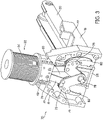
Figure 3 illustrates the fastener closing mechanism of the electrical fastening tool inFig. 1 ; -
Figures 4A-4C illustrate the fastener closing mechanism operation; -
Figure 5 illustrates a fastening tool according to an embodiment of the invention positioned on top of a workpiece; -
Figure 6 illustrates the fastener driving mechanism of the embodiment ofFigure 5 . -
Figure 7 is a sectional view of the fastener driving mechanism of the embodiment ofFigure 5 ; -
Figure 8 illustrates another view of the fastener driving mechanism of the embodiment ofFigure 5 ; and -
Figure 9 illustrates the fastener closing mechanism of the embodiment ofFigure 5 . - Reference will now be made in detail to the presently preferred embodiments of the invention, examples of which are illustrated in the accompanying drawings.
- Referring now more particularly to the drawings, there is shown in
Figure 1 a vertical right side view of a fastener driving tool, generally indicated at 10, which embodies the principles of the present invention. As shown, the tool is an electrically actuated portable type tool capable of driving staples and clinching the same into work pieces, such as carton flaps and the like, the staples being carried as a supply within the tool in the form of elongated preformed staples interconnected together in parallel relation and formed linearly within a magazine or in a coil form in a coil magazine. - As shown in
Figure 1 , thetool 10 includes a main casting or housing, generally indicated at 12, which provides ahandle portion 14 adapted to be gripped by the hand of an operator, avertical section 16 extending forwardly and downwardly from the forward end of thehandle 14. Thehousing 12 can be integral with a base 18 (e.g.Figure 2 ) and formed in a single casting. Alternatively, thehousing 12 and thebase 18 can be separately cast and the housing mounted onto the base. The housing and base unit include amagazine 20 for storing and arranging staples for delivery to a fastener or staple driving element (i.e. driver) 30. The magazine can be an elongated member as shown inFigures 2-3 in which staples are arranged linearly in parallel. Alternatively, the staples can be arranged in a coil for a more compact tool. The magazine includes apusher 22 for pushing staples from an insertion end of the tool to a delivery end of the tool where the staples can be driven by thestaple driver 30 and embedded into a workpiece W. Themagazine 20 can be coupled to aflange portion 19 of the base housing the staple driver. The magazine also includes amagazine release lever 24 to disconnect the magazine from the tool when a staple is jammed in the tool. - In one embodiment not according to the present invention the upper end portion of the forward section of the housing defines a solenoid housing or
casing 26 including a solenoid serving as a power source for the tool. In an embodiment of the present invention shown inFigures 5-9 a motor serves as the power source for the tool. - Provided at the lower portion of the
vertical housing section 16 is afastener drive track 28 within which is mounted thestaple driver 30.Staple driver 30 is moved through successive operating cycles, each of which includes a downward drive stroke and an upward return stroke. - For the purpose of effecting the movement of the
staple driver 30 through successive operative cycles of movement, there is provided an electrical solenoid assembly, generally indicated at 32, which is carried by thehousing structure 12 on thebase 18 in a position forwardly of thehandle 14 and rearwardly and above thefront wall 16 anddrive track 28. Preferably, the solenoid assembly constitutes a separately packaged sub-assembly within a casing (not shown). Asolenoid coil 34 is mounted within the main body portion of the casing. Mounted within thecoil 34 is a plunger orarmature 35 including a lower portion of suitable dielectric material. The upper portion of theplunger 35 is constituted by a piston (not shown) of suitable ferro-magnetic material which is guided by sliding movement through a closure wall (not shown) formed as a part of the solenoid casing. The piston is adapted to engage a bumper stop (not shown) for the purpose of determining the upper limiting position of theplunger structure 35. The guiding movement provided by the piston slidably supported within the wall together with the sliding movement of the lower end portion of theplunger 35 provides for successive reciprocating cycles of movement of thesolenoid plunger structure 35 along an axis of the drive stroke. - The
staple driver 30 is connected with the lower end of the solenoid plunger orarmature 35 of thesolenoid assembly 32 through a driver mounting block, generally indicated at 48, which may also be referred to as a mount. In an embodiment, themount 48 may be integral with thestaple driver 30. As a result, thesolenoid coil 34 acts as a linear actuator for actuating thestaple driver 30 through a drive stroke in thedrive track 28. - The
solenoid assembly 34 is manually actuated by a manual actuating mechanism, generally indicated at 50, inFigure 1 , which is operable to activate and deactivate thesolenoid coil 34 in response to the completion of the drive stroke of thesolenoid plunger 35. - As best shown in
Figure 1 , themanual actuating mechanism 50 includes atrigger member 52 moveably mounted to thehousing 12 in a location near thehandle portion 14 and is adapted to be digitally engaged by a user or operator grasping thehousing handle portion 14 with a hand. Thetrigger member 52 has a pair oflegs 54. The upper forward ends of the legs are pivoted to a pair of spaced dependingbracket portions 56 forming a part of the main casting orhousing 12. Eachleg 54 of thetrigger member 52 is apertured to receive the end of a pivotpin forming bolt 58 threadedly engaged within the associatedbracket position 56. The forward bight portion of thetrigger 52 is cut out to form a space for receiving a coil spring. One end of the coil spring (not shown) is connected to the trigger and the opposite end is connected with a pin (not shown) which extends laterally from a control lever 64. - The control lever 64 is mounted on one of the
bracket portions 56 by an adjusting mechanism, which provides for the adjustment of the pivotal axis of the control lever 64 with respect to thehousing 12. - A clinching assembly, which may be referred to as a clincher and generally indicated at 70 in
Figure 1 , is mounted proximal to the nose of the tool in a position to define the rearward lower portion of thedrive track 28. The driver mounting block (i.e. mount) 48 also serves to mount the clinchingassembly 70 at a position alongside thestaple driver 30. - As shown in
Figure 3 , theclincher 70 is connected to themount 48 by a pair oflinks 72. Thelinks 72 are pivotably connected to themount 48 through a pair of pivot pins 74. Theclincher 70 includes a pair ofclincher arms 76, which are pivoted to the lower end of thevertical housing section 16 by a pivot member generally indicated at 78 and are further pivotable on thelinks 72 through pivot pins 75. Eachclincher arm 76 has mounted on the outer end thereof anarcuate clincher anvil 80 which, when the clincher is disposed in its retracted position, as shown inFigure 3 , extends arcuately downwardly from the end of the associatedarm 76. Theclincher arms 76 may be formed with interior grooves to receive the ends of the legs of a staple being driven to guidingly move the legs inwardly to effect clinching thereof. Eachclincher anvil 80 may be integral with itsrespective clincher arm 76. In order to accomplish the clinching action, the clincher anvils 80 are moved downwardly and inwardly along an arcuate path into a clinching position. This movement is accomplished in response to the downward movement of themount 48 by means of the pair oflinks 72 pivoted at their upper ends to themount 48, by the pivot pins 74, and at their lower ends to an upper intermediate portion of an associatedclincher arm 76 as by apivot pin 75. - Referring now more particularly to
Figures 4A-4C , the construction and operation of theclincher 70 of the embodiments of the present invention is shown therein. - With the
tool 10 provided with a staple supply in the manner indicated above, the staples being formed in a U-shaped configuration; and with the leading staple S disposed within thedrive track 28, it will be understood that when the operator actuates thetrigger member 52, thesolenoid plunger 35 will be moved through a drive stroke carrying with it thestaple driver 30, and theclincher 70. - The solenoid, and also the motor assembly described and shown in
Figures 5-9 , provide a power source to the tool to operate the clincher assembly as shown inFigures 4A-4C . InFigure 4A , the tool is in a resting state. Thestaple driver 30 is in a top position before the actuating mechanism or trigger 52 is engaged by a user of thetool 10. In this state, the clincher anvils 80 are in an open position. The leading staple S is in the magazine and connected to the remaining supply of staples.Figure 4B illustrates the initial engagement of thetrigger 52 which causes thestaple driver 30 to move through the drive stroke. During the initial portion of the drive stroke, the lower end of thestaple driver 30 engages the crown C of the staple S within thedrive track 28 and moves the staple S downwardly. In addition, theclincher 70 is operated so that the clincher anvils 80 thereof are moved into a position to receive the free ends of the legs L of the staple S being driven as the latter move outwardly of the lower end of thedrive track 28 and into the work piece. The clincher anvils 80 contact with the legs L of the leading staple S which has been pushed to the delivery end of thetool 10 by thepusher 22 of themagazine 20. At this stage, the legs L of the staple are being pushed into the workpiece. InFigure 4C , thestaple driver 30 is in a bottom position while the clincher anvils 80 are closed and fully pivoted toward each other in a clinching position, bending the legs L of the leading staple S toward each other. The clincher anvils 80 are also forced into the workpiece to press the legs of the leading staple toward each other. By the end of the drive stroke of thesolenoid plunger 35, the legs of the driven staple are clinched on the clincher anvils 80 so that the staple S is clinched to the workpiece. As discussed herein, the clincher operation can also be driven by a motor assembly. - The body of the clincher arms can be metallic and formed from steel, for example. Alternatively, the body of the clincher arms can be titanium or any other rigid metal. Other materials that can be used to form the clincher arms include a rigid resin material, plastic or a composite material. Further, a combination of materials or material properties can be used for the clincher arms, as desired.
- In an embodiment of the present invention, as shown in
Figures 5-9 , the power source for the fastener tool, generally indicated at 100, may be a motor assembly. -
Figure 5 illustrates a vertical right side view of afastener driving tool 100, which embodies the principles of the present invention. As shown, thetool 100 is an electrically actuated portable type tool having a motor assembly for driving the staple driver to deliver a staple into a workpiece W, such as carton flaps of a corrugated fiberboard container. The staples, although shown as being carried as a supply within the tool in the form of a linear magazine, may also be carried in a roll for a coil magazine for a more compact tool. - In accordance with the teachings of the present embodiment, the
tool 100 includes a main casting or housing, generally indicated at 102, which provides ahandle portion 104 adapted to be gripped by the hand of an operator, avertical section 106 extending forwardly and downwardly from the forward end of thehandle 104. Thehousing 102 can be mounted on or integral with abase section 108 that includes amagazine 110 for storing and arranging staples for delivery to a staple driver. Themagazine 110 can be an elongated member as shown inFigures 5-9 in which staples are arranged linearly in parallel. Themagazine 110 includes a pusher for pushing staples from an insertion end of the tool to a delivery end of the tool where the staples can be driven by the staple driver and embedded into a workpiece W. Themagazine 110 also includes amagazine release lever 114 to disconnect the magazine from the tool when a staple is jammed in the tool. - As shown in
Figures 5-7 , thetool 100 also includes amotor housing 116, which can house amotor assembly 118, atransmission assembly 120 thestaple driver 30 and a control module (not shown). Themotor housing 116 can be arranged between thehandle 104 andmagazine 110, as shown inFigure 5 . Like elements have the same reference number as the same element in the embodiments herein. - The motor assembly includes a
motor 122 that can drive thetransmission 124, which in turn can actuate and advance thestaple driver 30 to strike the crown C of the leading staple S shown inFigures 4A-4C . - Actuation of the
staple driver 30 can drive staples which are sequentially fed from themagazine 110 into the clinchingassembly 70 then into a workpiece W. - The
motor 122 is actuated by thetrigger assembly 150. Thetrigger assembly 150 includes atrigger member 152 that is mechanically coupled to handle 104 and electrically coupled tomotor assembly 118 such that the trigger assembly selectively provides electric power to motor assembly when a user or operator of thetool 100 operates thetrigger 152 while holding thehandle portion 104. Themotor assembly 118 includes arotatable output shaft 119, which extends into thetransmission assembly 120. Amotor pinion 132 having a plurality of gear teeth is coupled for rotation with theoutput shaft 119. - With reference to
Figures 7 and8 , theoutput shaft 119 can connect an input orcrankshaft 130 of thetransmission assembly 120 to an output of themotor 122. A transmission housing such as thetransmission mounting brackets Figure 6 , can encase the transmission assembly 120 a portion of aoutput shaft 119, and various other components of the transmission assembly. An output shaft bearing 126 can be employed to journally support theoutput shaft 119, in thetransmission housing Figure 7 , thetransmission assembly 120 can include afirst drive gear 134, and asecond drive gear 136 that can be coupled for rotation with theoutput shaft 119 within the transmission housing. Thefirst drive gear 134 can be closer to themotor 122 relative to thesecond drive gear 136 Theoutput shaft 119, thefirst drive gear 134, and thesecond drive gear 136, can rotate at the same rotational speed. The speed is controlled by the control module. The control module ensures that the transmission has enough rotations to ensure that enough momentum can be generated to drive thestaple driver 30 into the workpiece W and to positively drive the staple driver in the downward drive stroke and the upward return stroke. - As shown in
Figure 9 , a crank 140 of the transmission assembly is connected through abushing 138 to thestaple driver 30 to transmit the force from the transmission to the and effectuate the downward drive stroke. The operation of the clinching assembly through the downward drive stroke is the same as that described above with respect toFigures 3 and4 . - Those skilled in the art will appreciate that the electrically powered driving tools described herein are powered by a battery pack.
- Although staples are illustrated, the embodiments described herein include, but are not limited to, nails, brads, clips or any such suitable fastener that could be driven into and clinched to the workpiece W.
Claims (10)
- A fastener driving tool (10; 100) comprising:a housing (12; 102);a drive track (28) within the housing;a magazine (20; 110) connected to the housing and configured to hold a supply of fasteners and to provide a leading fastener to the drive track;a driver (30) configured to move downward in the drive track and drive the leading fastener into a workpiece during a drive stroke, and upward in the drive track during a return stroke;a mount (48) operatively connected to the driver;a power source (26; 122) at least partially contained within the housing and configured to provide power to the driver to move the driver during the drive stroke and the return stroke; anda clincher (70) connected to the housing and the mount, the clincher being configured to engage the leading fastener during the drive stroke and move into a clinching position at the end of the drive stroke to clinch the fastener to the workpiece;characterised in that the fastener driving tool is a cordless electric fastener driving tool and wherein the power source comprises a motor (122) having a rotatable output shaft (119) and a transmission (120), which includes a plurality of planetary gear sets in series and a crank (140), operatively connected to the driver (30) via the crank (140) of the transmission (120), and wherein rotary movement of the rotatable output shaft translates to linear movement of the driver.
- The fastener driving tool according to claim 1, wherein the clincher (70) comprises:a first link (72) pivotably connected to the mount (48), and a second link (72) pivotably connected to the mount;a first clincher arm (76) pivotably connected to the first link and pivotably connected to the housing (12; 102), and a second clincher arm (76) pivotably connected to the second link and pivotably connected to the housing; anda first clincher anvil (80) connected to the first clincher arm at a first end thereof, and a second clincher anvil (80) connected to the second clincher arm at a first end thereof, wherein a second end of the first clincher anvil and a second end of the second clincher anvil are each configured to move downwardly and inwardly towards each other to engage the leading fastener during the drive stroke and clinch the leading fastener to the workpiece at the end of the drive stroke.
- The fastener driving tool according to claim 2, wherein the fasteners are staples, wherein each staple (S) comprises a crown (C) and two legs (L) extending from the crown, and wherein the driver (30) is configured to engage the crown and each of the second ends of the first and second clincher anvils is configured to engage one of the legs.
- The fastener driving tool according to claim 2, wherein the first clincher anvil (80) is integral with the first clincher arm (76), and the second clincher anvil (80) is integral with the second clincher arm (76).
- The fastener driving tool according to claim 2, wherein the first clincher anvil (80) and the second clincher anvil (80) each have an arcuate shape and extend arcuately downwardly from the respective second ends of the first clincher arm (76) and the second clincher arm (76).
- The fastener driving tool according to claim 5, wherein a distal tip of the first clincher anvil (80) and a distal tip of the second clincher anvil (80) are each configured to pierce through the workpiece as the first clincher anvil and the second clincher anvil move downwardly and inwardly into the clinching position.
- The fastener driving tool according to claim 1, wherein the mount (48) is integral with the driver (30).
- The fastener driving tool according to claim 1, further comprising a trigger (52) mechanically coupled to a handle portion (14) of the housing and electrically coupled to the motor (122) such that the trigger selectively provides electric power to the motor when a user of the fastener driving tool operates the trigger while holding the handle portion.
- The fastener driving tool according to claim 1, further comprising a trigger (52) moveably mounted to the housing and operatively connected to the power source, the trigger being configured to initiate the drive stroke when actuated by a user of the fastener driving tool.
- The fastener driving tool according to claim 9, wherein the housing comprises a handle portion (14) configured to be gripped by a hand of the user, the trigger (52) being moveably mounted to the housing in a location near the handle portion.
Applications Claiming Priority (2)
| Application Number | Priority Date | Filing Date | Title |
|---|---|---|---|
| US201261612649P | 2012-03-19 | 2012-03-19 | |
| US13/803,760 US20130240594A1 (en) | 2012-03-19 | 2013-03-14 | Cordless carton closer |
Publications (3)
| Publication Number | Publication Date |
|---|---|
| EP2641699A2 EP2641699A2 (en) | 2013-09-25 |
| EP2641699A3 EP2641699A3 (en) | 2018-04-11 |
| EP2641699B1 true EP2641699B1 (en) | 2022-06-22 |
Family
ID=48044547
Family Applications (1)
| Application Number | Title | Priority Date | Filing Date |
|---|---|---|---|
| EP13159542.3A Active EP2641699B1 (en) | 2012-03-19 | 2013-03-15 | Cordless carton closer |
Country Status (2)
| Country | Link |
|---|---|
| US (1) | US20130240594A1 (en) |
| EP (1) | EP2641699B1 (en) |
Families Citing this family (2)
| Publication number | Priority date | Publication date | Assignee | Title |
|---|---|---|---|---|
| US10946547B2 (en) * | 2018-12-03 | 2021-03-16 | Apex Mfg. Co., Ltd. | Electric striking device |
| CN115996818B (en) * | 2021-08-20 | 2025-09-05 | 康威瑞有限公司 | Use the double pull of the handle to tighten the corners of the box at the end of the core with a stapler |
Citations (3)
| Publication number | Priority date | Publication date | Assignee | Title |
|---|---|---|---|---|
| WO2002051591A1 (en) * | 2000-12-22 | 2002-07-04 | Senco Products, Inc. | Control module for flywheel operated hand tool |
| US20040060959A1 (en) * | 2002-09-30 | 2004-04-01 | Matsushita Electric Industrial Co., Ltd. | Clinch mechanism for stapler and electric stapler using the same |
| US6971567B1 (en) * | 2004-10-29 | 2005-12-06 | Black & Decker Inc. | Electronic control of a cordless fastening tool |
Family Cites Families (33)
| Publication number | Priority date | Publication date | Assignee | Title |
|---|---|---|---|---|
| US2899679A (en) * | 1959-08-18 | allen | ||
| BE544890A (en) * | ||||
| US2182594A (en) * | 1937-11-24 | 1939-12-05 | Elmon C Gillette | Box stitching machine |
| US2770804A (en) * | 1954-06-23 | 1956-11-20 | Schafroth Werner | Stapling machine |
| US2987725A (en) * | 1958-02-24 | 1961-06-13 | Internat Staple And Machine Co | Staple driving and forming blade mechanism |
| US3064626A (en) * | 1960-12-05 | 1962-11-20 | Bostitch Inc | Power-driven stapling machine |
| US3224657A (en) * | 1962-05-31 | 1965-12-21 | Speedfast Corp | Blind anvil fastening device |
| BE647880A (en) * | 1963-05-13 | |||
| US3279673A (en) * | 1964-10-05 | 1966-10-18 | Schafroth | Stapling machine |
| US3313463A (en) * | 1965-07-15 | 1967-04-11 | Boucher Gerard | Carpet jointing machine |
| US3403832A (en) * | 1967-08-31 | 1968-10-01 | Robert W. Pabich | Combination staple former and stapling machine |
| US3504837A (en) * | 1968-04-24 | 1970-04-07 | Werner Schafroth | Stapling machine and method of forming staples |
| US3504839A (en) * | 1968-04-24 | 1970-04-07 | Werner Schafroth | Stapling machine |
| US4449660A (en) * | 1981-04-30 | 1984-05-22 | Black & Decker Inc. | Fastener tool |
| DE3237616A1 (en) * | 1982-10-11 | 1984-04-12 | Hilti AG, 9494 Schaan | DRIVING DEVICE FOR NAILS AND THE LIKE FASTENING ELEMENTS |
| US4671444A (en) * | 1985-05-06 | 1987-06-09 | Textron Inc. | Stapler with improved jam clearing mechanism |
| US4858813A (en) * | 1985-11-01 | 1989-08-22 | Arrow Fastener Company, Inc. | Staple driving tool |
| US5040400A (en) * | 1990-12-10 | 1991-08-20 | G.L. Group, Ltd. | Power actuated tool for installing metal corner strip |
| JP2568736Y2 (en) * | 1993-12-06 | 1998-04-15 | マックス株式会社 | Portable electric staple driving machine |
| JP3598765B2 (en) * | 1997-09-24 | 2004-12-08 | マックス株式会社 | Staple clinch mechanism in stapler |
| IT1319864B1 (en) * | 2000-03-17 | 2003-11-03 | Giuseppe Raffoni | DEVICE TO IMPLEMENT IN THE EQUIPMENT THAT REALIZE RECTANGULAR FRAMES, THE PERFECT COMBINATION OF THE STRIPS TO BE JOINED IN |
| JP4644973B2 (en) * | 2000-06-01 | 2011-03-09 | マックス株式会社 | Electric stapler |
| GB2376912B (en) * | 2001-06-27 | 2003-04-09 | Isaberg Rapid Ab | Clinching mechanism for staplers |
| GB2406070B (en) * | 2002-07-25 | 2005-06-29 | Yih Kai Entpr Co Ltd | Handy electric nailing gun |
| JP4078924B2 (en) * | 2002-08-30 | 2008-04-23 | マックス株式会社 | Electric stapler |
| JP4269661B2 (en) * | 2002-11-26 | 2009-05-27 | マックス株式会社 | Electric stapler |
| US7146837B2 (en) * | 2003-09-16 | 2006-12-12 | Schmidt Christopher J | Power crimping tool |
| US7922060B2 (en) * | 2004-01-13 | 2011-04-12 | Max Co., Ltd. | Stapler |
| US7331403B2 (en) * | 2004-04-02 | 2008-02-19 | Black & Decker Inc. | Lock-out for activation arm mechanism in a power tool |
| US7108165B2 (en) * | 2004-12-08 | 2006-09-19 | Apex Mfg. Co., Ltd. | Stapler capable of cutting staple legs one after another |
| US7311236B2 (en) * | 2005-04-25 | 2007-12-25 | Tsi Manufacturing Llc | Electric stapler having two anvil plates and workpiece sensing controller |
| US8104659B2 (en) * | 2006-03-27 | 2012-01-31 | Stanley Black & Decker, Inc. | Electromagnetic stapler with a manually adjustable depth adjuster |
| JP4507211B2 (en) * | 2007-09-03 | 2010-07-21 | 日立工機株式会社 | Driving machine |
-
2013
- 2013-03-14 US US13/803,760 patent/US20130240594A1/en not_active Abandoned
- 2013-03-15 EP EP13159542.3A patent/EP2641699B1/en active Active
Patent Citations (3)
| Publication number | Priority date | Publication date | Assignee | Title |
|---|---|---|---|---|
| WO2002051591A1 (en) * | 2000-12-22 | 2002-07-04 | Senco Products, Inc. | Control module for flywheel operated hand tool |
| US20040060959A1 (en) * | 2002-09-30 | 2004-04-01 | Matsushita Electric Industrial Co., Ltd. | Clinch mechanism for stapler and electric stapler using the same |
| US6971567B1 (en) * | 2004-10-29 | 2005-12-06 | Black & Decker Inc. | Electronic control of a cordless fastening tool |
Also Published As
| Publication number | Publication date |
|---|---|
| EP2641699A3 (en) | 2018-04-11 |
| EP2641699A2 (en) | 2013-09-25 |
| US20130240594A1 (en) | 2013-09-19 |
Similar Documents
| Publication | Publication Date | Title |
|---|---|---|
| EP2679344B1 (en) | Cordless carton closing tool and method of replacing a carton closer clinching member | |
| US12365069B2 (en) | Power tool | |
| EP2679347B1 (en) | Cordless fastening tool control system | |
| US8534527B2 (en) | Cordless framing nailer | |
| US9844865B2 (en) | Driver tool | |
| US9827659B2 (en) | Driver tool | |
| EP3478457B1 (en) | Cordless concrete nailer with improved power take-off mechanism | |
| EP2679345B1 (en) | Carton closing tool having tool-free adjustment members | |
| CN113165150B (en) | Driving tool | |
| EP2944427B1 (en) | Motor-driven fastening tool | |
| JP2011025362A (en) | Driving tool | |
| WO2020214558A1 (en) | Powered fastener driver | |
| WO2025059311A1 (en) | Fastener tool with continuously powered flywheel | |
| EP2641699A2 (en) | Cordless carton closer | |
| US8740032B2 (en) | Electric stapler | |
| US20250312906A1 (en) | Driver member for a fastening tool | |
| US20250375864A1 (en) | Driver blade guide for a fastening tool |
Legal Events
| Date | Code | Title | Description |
|---|---|---|---|
| PUAI | Public reference made under article 153(3) epc to a published international application that has entered the european phase |
Free format text: ORIGINAL CODE: 0009012 |
|
| AK | Designated contracting states |
Kind code of ref document: A2 Designated state(s): AL AT BE BG CH CY CZ DE DK EE ES FI FR GB GR HR HU IE IS IT LI LT LU LV MC MK MT NL NO PL PT RO RS SE SI SK SM TR |
|
| AX | Request for extension of the european patent |
Extension state: BA ME |
|
| PUAL | Search report despatched |
Free format text: ORIGINAL CODE: 0009013 |
|
| AK | Designated contracting states |
Kind code of ref document: A3 Designated state(s): AL AT BE BG CH CY CZ DE DK EE ES FI FR GB GR HR HU IE IS IT LI LT LU LV MC MK MT NL NO PL PT RO RS SE SI SK SM TR |
|
| AX | Request for extension of the european patent |
Extension state: BA ME |
|
| RIC1 | Information provided on ipc code assigned before grant |
Ipc: B25B 27/14 20060101AFI20180306BHEP Ipc: B25C 5/02 20060101ALI20180306BHEP |
|
| STAA | Information on the status of an ep patent application or granted ep patent |
Free format text: STATUS: REQUEST FOR EXAMINATION WAS MADE |
|
| 17P | Request for examination filed |
Effective date: 20180912 |
|
| RBV | Designated contracting states (corrected) |
Designated state(s): AL AT BE BG CH CY CZ DE DK EE ES FI FR GB GR HR HU IE IS IT LI LT LU LV MC MK MT NL NO PL PT RO RS SE SI SK SM TR |
|
| STAA | Information on the status of an ep patent application or granted ep patent |
Free format text: STATUS: EXAMINATION IS IN PROGRESS |
|
| 17Q | First examination report despatched |
Effective date: 20190313 |
|
| GRAP | Despatch of communication of intention to grant a patent |
Free format text: ORIGINAL CODE: EPIDOSNIGR1 |
|
| STAA | Information on the status of an ep patent application or granted ep patent |
Free format text: STATUS: GRANT OF PATENT IS INTENDED |
|
| INTG | Intention to grant announced |
Effective date: 20210722 |
|
| GRAJ | Information related to disapproval of communication of intention to grant by the applicant or resumption of examination proceedings by the epo deleted |
Free format text: ORIGINAL CODE: EPIDOSDIGR1 |
|
| STAA | Information on the status of an ep patent application or granted ep patent |
Free format text: STATUS: EXAMINATION IS IN PROGRESS |
|
| INTC | Intention to grant announced (deleted) | ||
| GRAJ | Information related to disapproval of communication of intention to grant by the applicant or resumption of examination proceedings by the epo deleted |
Free format text: ORIGINAL CODE: EPIDOSDIGR1 |
|
| GRAP | Despatch of communication of intention to grant a patent |
Free format text: ORIGINAL CODE: EPIDOSNIGR1 |
|
| GRAP | Despatch of communication of intention to grant a patent |
Free format text: ORIGINAL CODE: EPIDOSNIGR1 |
|
| GRAJ | Information related to disapproval of communication of intention to grant by the applicant or resumption of examination proceedings by the epo deleted |
Free format text: ORIGINAL CODE: EPIDOSDIGR1 |
|
| GRAP | Despatch of communication of intention to grant a patent |
Free format text: ORIGINAL CODE: EPIDOSNIGR1 |
|
| STAA | Information on the status of an ep patent application or granted ep patent |
Free format text: STATUS: GRANT OF PATENT IS INTENDED |
|
| INTG | Intention to grant announced |
Effective date: 20211223 |
|
| GRAJ | Information related to disapproval of communication of intention to grant by the applicant or resumption of examination proceedings by the epo deleted |
Free format text: ORIGINAL CODE: EPIDOSDIGR1 |
|
| STAA | Information on the status of an ep patent application or granted ep patent |
Free format text: STATUS: EXAMINATION IS IN PROGRESS |
|
| GRAP | Despatch of communication of intention to grant a patent |
Free format text: ORIGINAL CODE: EPIDOSNIGR1 |
|
| STAA | Information on the status of an ep patent application or granted ep patent |
Free format text: STATUS: GRANT OF PATENT IS INTENDED |
|
| INTG | Intention to grant announced |
Effective date: 20220211 |
|
| GRAS | Grant fee paid |
Free format text: ORIGINAL CODE: EPIDOSNIGR3 |
|
| GRAA | (expected) grant |
Free format text: ORIGINAL CODE: 0009210 |
|
| STAA | Information on the status of an ep patent application or granted ep patent |
Free format text: STATUS: THE PATENT HAS BEEN GRANTED |
|
| AK | Designated contracting states |
Kind code of ref document: B1 Designated state(s): AL AT BE BG CH CY CZ DE DK EE ES FI FR GB GR HR HU IE IS IT LI LT LU LV MC MK MT NL NO PL PT RO RS SE SI SK SM TR |
|
| REG | Reference to a national code |
Ref country code: GB Ref legal event code: FG4D |
|
| REG | Reference to a national code |
Ref country code: CH Ref legal event code: EP |
|
| REG | Reference to a national code |
Ref country code: DE Ref legal event code: R096 Ref document number: 602013081891 Country of ref document: DE |
|
| REG | Reference to a national code |
Ref country code: AT Ref legal event code: REF Ref document number: 1499470 Country of ref document: AT Kind code of ref document: T Effective date: 20220715 |
|
| REG | Reference to a national code |
Ref country code: IE Ref legal event code: FG4D |
|
| REG | Reference to a national code |
Ref country code: LT Ref legal event code: MG9D |
|
| REG | Reference to a national code |
Ref country code: NL Ref legal event code: MP Effective date: 20220622 |
|
| PG25 | Lapsed in a contracting state [announced via postgrant information from national office to epo] |
Ref country code: SE Free format text: LAPSE BECAUSE OF FAILURE TO SUBMIT A TRANSLATION OF THE DESCRIPTION OR TO PAY THE FEE WITHIN THE PRESCRIBED TIME-LIMIT Effective date: 20220622 Ref country code: NO Free format text: LAPSE BECAUSE OF FAILURE TO SUBMIT A TRANSLATION OF THE DESCRIPTION OR TO PAY THE FEE WITHIN THE PRESCRIBED TIME-LIMIT Effective date: 20220922 Ref country code: LT Free format text: LAPSE BECAUSE OF FAILURE TO SUBMIT A TRANSLATION OF THE DESCRIPTION OR TO PAY THE FEE WITHIN THE PRESCRIBED TIME-LIMIT Effective date: 20220622 Ref country code: HR Free format text: LAPSE BECAUSE OF FAILURE TO SUBMIT A TRANSLATION OF THE DESCRIPTION OR TO PAY THE FEE WITHIN THE PRESCRIBED TIME-LIMIT Effective date: 20220622 Ref country code: GR Free format text: LAPSE BECAUSE OF FAILURE TO SUBMIT A TRANSLATION OF THE DESCRIPTION OR TO PAY THE FEE WITHIN THE PRESCRIBED TIME-LIMIT Effective date: 20220923 Ref country code: FI Free format text: LAPSE BECAUSE OF FAILURE TO SUBMIT A TRANSLATION OF THE DESCRIPTION OR TO PAY THE FEE WITHIN THE PRESCRIBED TIME-LIMIT Effective date: 20220622 Ref country code: BG Free format text: LAPSE BECAUSE OF FAILURE TO SUBMIT A TRANSLATION OF THE DESCRIPTION OR TO PAY THE FEE WITHIN THE PRESCRIBED TIME-LIMIT Effective date: 20220922 |
|
| REG | Reference to a national code |
Ref country code: AT Ref legal event code: MK05 Ref document number: 1499470 Country of ref document: AT Kind code of ref document: T Effective date: 20220622 |
|
| PG25 | Lapsed in a contracting state [announced via postgrant information from national office to epo] |
Ref country code: RS Free format text: LAPSE BECAUSE OF FAILURE TO SUBMIT A TRANSLATION OF THE DESCRIPTION OR TO PAY THE FEE WITHIN THE PRESCRIBED TIME-LIMIT Effective date: 20220622 Ref country code: LV Free format text: LAPSE BECAUSE OF FAILURE TO SUBMIT A TRANSLATION OF THE DESCRIPTION OR TO PAY THE FEE WITHIN THE PRESCRIBED TIME-LIMIT Effective date: 20220622 |
|
| PG25 | Lapsed in a contracting state [announced via postgrant information from national office to epo] |
Ref country code: NL Free format text: LAPSE BECAUSE OF FAILURE TO SUBMIT A TRANSLATION OF THE DESCRIPTION OR TO PAY THE FEE WITHIN THE PRESCRIBED TIME-LIMIT Effective date: 20220622 |
|
| PG25 | Lapsed in a contracting state [announced via postgrant information from national office to epo] |
Ref country code: SM Free format text: LAPSE BECAUSE OF FAILURE TO SUBMIT A TRANSLATION OF THE DESCRIPTION OR TO PAY THE FEE WITHIN THE PRESCRIBED TIME-LIMIT Effective date: 20220622 Ref country code: SK Free format text: LAPSE BECAUSE OF FAILURE TO SUBMIT A TRANSLATION OF THE DESCRIPTION OR TO PAY THE FEE WITHIN THE PRESCRIBED TIME-LIMIT Effective date: 20220622 Ref country code: RO Free format text: LAPSE BECAUSE OF FAILURE TO SUBMIT A TRANSLATION OF THE DESCRIPTION OR TO PAY THE FEE WITHIN THE PRESCRIBED TIME-LIMIT Effective date: 20220622 Ref country code: PT Free format text: LAPSE BECAUSE OF FAILURE TO SUBMIT A TRANSLATION OF THE DESCRIPTION OR TO PAY THE FEE WITHIN THE PRESCRIBED TIME-LIMIT Effective date: 20221024 Ref country code: ES Free format text: LAPSE BECAUSE OF FAILURE TO SUBMIT A TRANSLATION OF THE DESCRIPTION OR TO PAY THE FEE WITHIN THE PRESCRIBED TIME-LIMIT Effective date: 20220622 Ref country code: EE Free format text: LAPSE BECAUSE OF FAILURE TO SUBMIT A TRANSLATION OF THE DESCRIPTION OR TO PAY THE FEE WITHIN THE PRESCRIBED TIME-LIMIT Effective date: 20220622 Ref country code: CZ Free format text: LAPSE BECAUSE OF FAILURE TO SUBMIT A TRANSLATION OF THE DESCRIPTION OR TO PAY THE FEE WITHIN THE PRESCRIBED TIME-LIMIT Effective date: 20220622 Ref country code: AT Free format text: LAPSE BECAUSE OF FAILURE TO SUBMIT A TRANSLATION OF THE DESCRIPTION OR TO PAY THE FEE WITHIN THE PRESCRIBED TIME-LIMIT Effective date: 20220622 |
|
| PG25 | Lapsed in a contracting state [announced via postgrant information from national office to epo] |
Ref country code: PL Free format text: LAPSE BECAUSE OF FAILURE TO SUBMIT A TRANSLATION OF THE DESCRIPTION OR TO PAY THE FEE WITHIN THE PRESCRIBED TIME-LIMIT Effective date: 20220622 Ref country code: IS Free format text: LAPSE BECAUSE OF FAILURE TO SUBMIT A TRANSLATION OF THE DESCRIPTION OR TO PAY THE FEE WITHIN THE PRESCRIBED TIME-LIMIT Effective date: 20221022 |
|
| REG | Reference to a national code |
Ref country code: DE Ref legal event code: R097 Ref document number: 602013081891 Country of ref document: DE |
|
| PG25 | Lapsed in a contracting state [announced via postgrant information from national office to epo] |
Ref country code: AL Free format text: LAPSE BECAUSE OF FAILURE TO SUBMIT A TRANSLATION OF THE DESCRIPTION OR TO PAY THE FEE WITHIN THE PRESCRIBED TIME-LIMIT Effective date: 20220622 |
|
| PG25 | Lapsed in a contracting state [announced via postgrant information from national office to epo] |
Ref country code: DK Free format text: LAPSE BECAUSE OF FAILURE TO SUBMIT A TRANSLATION OF THE DESCRIPTION OR TO PAY THE FEE WITHIN THE PRESCRIBED TIME-LIMIT Effective date: 20220622 |
|
| PLBE | No opposition filed within time limit |
Free format text: ORIGINAL CODE: 0009261 |
|
| STAA | Information on the status of an ep patent application or granted ep patent |
Free format text: STATUS: NO OPPOSITION FILED WITHIN TIME LIMIT |
|
| 26N | No opposition filed |
Effective date: 20230323 |
|
| PG25 | Lapsed in a contracting state [announced via postgrant information from national office to epo] |
Ref country code: SI Free format text: LAPSE BECAUSE OF FAILURE TO SUBMIT A TRANSLATION OF THE DESCRIPTION OR TO PAY THE FEE WITHIN THE PRESCRIBED TIME-LIMIT Effective date: 20220622 |
|
| P01 | Opt-out of the competence of the unified patent court (upc) registered |
Effective date: 20230912 |
|
| PG25 | Lapsed in a contracting state [announced via postgrant information from national office to epo] |
Ref country code: MC Free format text: LAPSE BECAUSE OF FAILURE TO SUBMIT A TRANSLATION OF THE DESCRIPTION OR TO PAY THE FEE WITHIN THE PRESCRIBED TIME-LIMIT Effective date: 20220622 |
|
| REG | Reference to a national code |
Ref country code: CH Ref legal event code: PL |
|
| REG | Reference to a national code |
Ref country code: BE Ref legal event code: MM Effective date: 20230331 |
|
| PG25 | Lapsed in a contracting state [announced via postgrant information from national office to epo] |
Ref country code: LU Free format text: LAPSE BECAUSE OF NON-PAYMENT OF DUE FEES Effective date: 20230315 |
|
| REG | Reference to a national code |
Ref country code: IE Ref legal event code: MM4A |
|
| PG25 | Lapsed in a contracting state [announced via postgrant information from national office to epo] |
Ref country code: LI Free format text: LAPSE BECAUSE OF NON-PAYMENT OF DUE FEES Effective date: 20230331 Ref country code: IT Free format text: LAPSE BECAUSE OF FAILURE TO SUBMIT A TRANSLATION OF THE DESCRIPTION OR TO PAY THE FEE WITHIN THE PRESCRIBED TIME-LIMIT Effective date: 20220622 Ref country code: IE Free format text: LAPSE BECAUSE OF NON-PAYMENT OF DUE FEES Effective date: 20230315 Ref country code: FR Free format text: LAPSE BECAUSE OF NON-PAYMENT OF DUE FEES Effective date: 20230331 Ref country code: CH Free format text: LAPSE BECAUSE OF NON-PAYMENT OF DUE FEES Effective date: 20230331 |
|
| PG25 | Lapsed in a contracting state [announced via postgrant information from national office to epo] |
Ref country code: BE Free format text: LAPSE BECAUSE OF NON-PAYMENT OF DUE FEES Effective date: 20230331 |
|
| PG25 | Lapsed in a contracting state [announced via postgrant information from national office to epo] |
Ref country code: BG Free format text: LAPSE BECAUSE OF FAILURE TO SUBMIT A TRANSLATION OF THE DESCRIPTION OR TO PAY THE FEE WITHIN THE PRESCRIBED TIME-LIMIT Effective date: 20220622 |
|
| PG25 | Lapsed in a contracting state [announced via postgrant information from national office to epo] |
Ref country code: BG Free format text: LAPSE BECAUSE OF FAILURE TO SUBMIT A TRANSLATION OF THE DESCRIPTION OR TO PAY THE FEE WITHIN THE PRESCRIBED TIME-LIMIT Effective date: 20220622 |
|
| PG25 | Lapsed in a contracting state [announced via postgrant information from national office to epo] |
Ref country code: CY Free format text: LAPSE BECAUSE OF FAILURE TO SUBMIT A TRANSLATION OF THE DESCRIPTION OR TO PAY THE FEE WITHIN THE PRESCRIBED TIME-LIMIT; INVALID AB INITIO Effective date: 20130315 |
|
| PG25 | Lapsed in a contracting state [announced via postgrant information from national office to epo] |
Ref country code: HU Free format text: LAPSE BECAUSE OF FAILURE TO SUBMIT A TRANSLATION OF THE DESCRIPTION OR TO PAY THE FEE WITHIN THE PRESCRIBED TIME-LIMIT; INVALID AB INITIO Effective date: 20130315 |
|
| PG25 | Lapsed in a contracting state [announced via postgrant information from national office to epo] |
Ref country code: TR Free format text: LAPSE BECAUSE OF FAILURE TO SUBMIT A TRANSLATION OF THE DESCRIPTION OR TO PAY THE FEE WITHIN THE PRESCRIBED TIME-LIMIT Effective date: 20220622 |
|
| PGFP | Annual fee paid to national office [announced via postgrant information from national office to epo] |
Ref country code: GB Payment date: 20260324 Year of fee payment: 14 |
|
| PGFP | Annual fee paid to national office [announced via postgrant information from national office to epo] |
Ref country code: DE Payment date: 20260320 Year of fee payment: 14 |