EP2641672A1 - Method for evaluating the installation of blind rivets, method and system for installing blind rivets, method and system for obtaining a pattern, and aircraft - Google Patents
Method for evaluating the installation of blind rivets, method and system for installing blind rivets, method and system for obtaining a pattern, and aircraft Download PDFInfo
- Publication number
- EP2641672A1 EP2641672A1 EP12382106.8A EP12382106A EP2641672A1 EP 2641672 A1 EP2641672 A1 EP 2641672A1 EP 12382106 A EP12382106 A EP 12382106A EP 2641672 A1 EP2641672 A1 EP 2641672A1
- Authority
- EP
- European Patent Office
- Prior art keywords
- rivet
- installation
- time
- cycle time
- unsuitable
- Prior art date
- Legal status (The legal status is an assumption and is not a legal conclusion. Google has not performed a legal analysis and makes no representation as to the accuracy of the status listed.)
- Withdrawn
Links
- 238000009434 installation Methods 0.000 title claims abstract description 105
- 238000000034 method Methods 0.000 title claims abstract description 66
- 238000002604 ultrasonography Methods 0.000 claims description 8
- 238000012545 processing Methods 0.000 claims description 6
- 238000013481 data capture Methods 0.000 claims description 3
- 238000012795 verification Methods 0.000 claims description 3
- 238000012544 monitoring process Methods 0.000 description 7
- 238000011156 evaluation Methods 0.000 description 5
- 230000000644 propagated effect Effects 0.000 description 5
- 238000002474 experimental method Methods 0.000 description 4
- 238000003754 machining Methods 0.000 description 4
- 238000004458 analytical method Methods 0.000 description 2
- 238000012512 characterization method Methods 0.000 description 2
- 238000005259 measurement Methods 0.000 description 2
- 238000013459 approach Methods 0.000 description 1
- 230000005540 biological transmission Effects 0.000 description 1
- 230000007547 defect Effects 0.000 description 1
- 230000001066 destructive effect Effects 0.000 description 1
- 238000006073 displacement reaction Methods 0.000 description 1
- 238000007689 inspection Methods 0.000 description 1
- 238000011900 installation process Methods 0.000 description 1
- 238000004519 manufacturing process Methods 0.000 description 1
- 230000000704 physical effect Effects 0.000 description 1
- 238000003908 quality control method Methods 0.000 description 1
- 238000013441 quality evaluation Methods 0.000 description 1
Images


Classifications
-
- G—PHYSICS
- G01—MEASURING; TESTING
- G01N—INVESTIGATING OR ANALYSING MATERIALS BY DETERMINING THEIR CHEMICAL OR PHYSICAL PROPERTIES
- G01N29/00—Investigating or analysing materials by the use of ultrasonic, sonic or infrasonic waves; Visualisation of the interior of objects by transmitting ultrasonic or sonic waves through the object
- G01N29/04—Analysing solids
- G01N29/07—Analysing solids by measuring propagation velocity or propagation time of acoustic waves
-
- B—PERFORMING OPERATIONS; TRANSPORTING
- B21—MECHANICAL METAL-WORKING WITHOUT ESSENTIALLY REMOVING MATERIAL; PUNCHING METAL
- B21J—FORGING; HAMMERING; PRESSING METAL; RIVETING; FORGE FURNACES
- B21J15/00—Riveting
- B21J15/10—Riveting machines
- B21J15/28—Control devices specially adapted to riveting machines not restricted to one of the preceding subgroups
-
- B—PERFORMING OPERATIONS; TRANSPORTING
- B21—MECHANICAL METAL-WORKING WITHOUT ESSENTIALLY REMOVING MATERIAL; PUNCHING METAL
- B21J—FORGING; HAMMERING; PRESSING METAL; RIVETING; FORGE FURNACES
- B21J15/00—Riveting
- B21J15/10—Riveting machines
- B21J15/28—Control devices specially adapted to riveting machines not restricted to one of the preceding subgroups
- B21J15/285—Control devices specially adapted to riveting machines not restricted to one of the preceding subgroups for controlling the rivet upset cycle
-
- G—PHYSICS
- G01—MEASURING; TESTING
- G01N—INVESTIGATING OR ANALYSING MATERIALS BY DETERMINING THEIR CHEMICAL OR PHYSICAL PROPERTIES
- G01N29/00—Investigating or analysing materials by the use of ultrasonic, sonic or infrasonic waves; Visualisation of the interior of objects by transmitting ultrasonic or sonic waves through the object
- G01N29/34—Generating the ultrasonic, sonic or infrasonic waves, e.g. electronic circuits specially adapted therefor
- G01N29/348—Generating the ultrasonic, sonic or infrasonic waves, e.g. electronic circuits specially adapted therefor with frequency characteristics, e.g. single frequency signals, chirp signals
-
- G—PHYSICS
- G01—MEASURING; TESTING
- G01N—INVESTIGATING OR ANALYSING MATERIALS BY DETERMINING THEIR CHEMICAL OR PHYSICAL PROPERTIES
- G01N2291/00—Indexing codes associated with group G01N29/00
- G01N2291/26—Scanned objects
- G01N2291/269—Various geometry objects
- G01N2291/2691—Bolts, screws, heads
Definitions
- the present invention relates to a method and system for evaluating the installation of blind rivets used in attaching structures, a system and method for generating a pattern relating installation "cycle time” and "travel time”, and an aircraft comprising a structure installed with the systems described above.
- blind rivets are widely used in closed aeronautical structures, where attachments have very restricted access on one of the sides, with no possibility of accessing or even viewing the rear part of the attachment. Consequently, the rivet quality evaluation process is carried out exclusively from the access face ('exposed face').
- blind rivets are inserted in the corresponding holes, and the riveting process is carried out until the stem of the rivet breaks, the rivet being installed.
- accessing the blind face (or unexposed face) is not possible, it is not possible to carry out a complete quality control of the attachment.
- a system which, in a non-destructive way, informs of the correct installation of rivets, it is necessary to assure the correct installation of the rivets with maximum assurance.
- the method proposed in GB2425179 is to be applied once the rivet is completely installed, and is intended for analysing riveted attachments of the same material or different materials. Said method is based on analyzing the electrical impedance of the rivet. It consists of measuring the electrical impedance of the rivet to be evaluated by means of using an ultrasonic generator in a narrow bandwidth. Both the real and complex electrical impedance measured are compared with previously established reference thresholds.
- the main technical problem which the invention solves is that of finding a technical solution to the contactless evaluation of blind rivets installed in closed structures or structures for which it is complicated or costly to access the "unexposed face", based on the analysis of the riveting step and the subsequent evaluation for immediately classifying the rivet as suitable or unsuitable.
- the present invention solves the problem described above by means of a non-invasive method for evaluating the installation of a blind rivet used in attaching structures according to claim 1, a system for installing blind rivets in structures according to claim 7, a method for generating a pattern relating "cycle time” with "travel time” according to claim 9, a system for generating a pattern according to claim 10, a system for installing and evaluating the installation of blind rivets according to claim 11 and an aircraft according to claim 12.
- the invention relates to a non-invasive method for evaluating the installation of a blind rivet used in attaching structures, where the blind rivet comprises a stem, an installation nut, a break notch, cut-off points and a bushing, characterised by comprising the steps of:
- the cycle time is obtained as the time elapsed between an event representing the start of the installation cycle and an event representing the end of the cycle. This time is represented as "y 0 ".
- the sound is a mechanical vibration which is propagated in materials.
- a generator generates the sound waves and they are transmitted through the installed blind rivet.
- Sound waves are only propagated through a material means, therefore when a wave reaches the boundary of the material in which it is being propagated it cannot continue to advance and is reflected. If there is another material in the boundary, part of the wave is propagated in the second material and part is reflected in the first material. The fact that sound is transmitted and reflected allows it to be used to find out some physical properties of the material in which they are propagated.
- the "travel time” measurement is directly related to the length of the stem of the rivet after its complete installation, including the machining of the stem if the application so requires. This time is represented as "x 0 ".
- the receiver receives the sound waves which are reflected at the end of the travel through the installed blind rivet.
- the total time from the transmission of the wave through the installed blind rivet and the reception of the reflected sound wave is called "travel time”.
- a characterising pattern of installation "cycle time” and "travel time” is provided in this step.
- the pattern is a border separating two areas in a graph of coordinates (x, y).
- An area, the "suitable area” corresponds to pairs (x, y) for rivets the installations of which are “suitable”
- the other area, “the unsuitable area” corresponds to pairs (x, y) of rivets the installations of which are “unsuitable”.
- the time relation value of the installed rivet (x 0 ,y 0 ) is compared with the time relation pattern in this step, obtaining a position in the plan in which to represent the installation performed.
- y f(x)
- the installation is immediately classified as suitable or unsuitable. In other words, if the representation of the installation is located in the area of the "suitable area" plan (x, y), the installation is considered “suitable”, and if it is located outside this area, the installation is considered "unsuitable”.
- the method of the invention is an alternative method to the state of the art, with a different approach, which is based on analysing the riveting step (during the process) and analysing information of the end result (after riveting).
- the contrast of the information obtained with a pattern according to the method proposed in the present invention is an instant and reliable tool for classifying blind rivets.
- a system for installing blind rivets in structures implementing the method described above and comprising a riveting machine with means for measuring the "cycle time” and a sound wave transmitter with means for injecting said sound waves in an installed rivet and means for measuring the "travel time”.
- This time the cycle time to create the pattern is represented as y p .
- This time is represented as y A and defines the minimum time necessary to install a blind rivet. It is likewise physically necessary for there to be a maximum cycle or installation time and this time is represented as y B .
- the travel time to create the pattern is represented as x p .
- x A a minimum represented as x A and it defines the minimum travel time of a sound wave and its reflection through the installed blind rivet.
- x B a maximum length for which a maximum travel time, x B , is associated.
- the x p , y p values thereof are considered and are represented in a graph of coordinates (x, y).
- suitable installation or "unsuitable installation”.
- the quality level of each installation is determined depending on the user implementing the method.
- Dividing the plan in regions, as well as the quality level associated with each region, is performed depending on a user and the quality requirements considered by the user.
- the regions can be determined as regions in which the quality level of the installation of the contained rivets is predominantly the same. There can even be regions of uncertainty, for example the borders, in which there is no associated quality level, and the rivets in said areas do not have associated quality level.
- a system for creating a time relation pattern characterised in that it comprises:
- a system for installing and evaluating blind rivets comprising
- an aircraft comprising at least one rivet installed by a system for installing and evaluating blind rivets like that of the fifth inventive aspect.
- the present invention relates to a method for evaluating the installation of a blind rivet used in attaching closed structures or structures for which it is complicated or costly to access the "unexposed face" for verifying whether or not the rivets have been correctly installed.
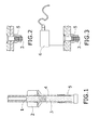
- An example of a blind rivet is depicted in Figure 1 .
- a pull-through blind rivet with a countersunk head can be seen in this figure. It shows the different parts of a rivet: stem (1), installation nut (2), break notch (3), cut-off points (4) and bushing (5).
- Figure 2 shows the rivet of Figure 1 installed in a structure where the bushing (5) is folded and can be seen abutting with the structure to prevent the rivet from coming out.
- the length of the rivet is represented as less than in Figure 1 due to the breaking of the stem (1).
- the non-invasive method for evaluating the installation of a blind rivet used in attaching structures comprises the steps of:
- the sound waves transmitted in step b) of the method for evaluating the installation of the rivet are ultrasounds, i.e., frequency thereof exceeds 20 KHz. This feature provides the method with discretion since the human ear is not capable of perceiving sounds at this frequency. In a particular embodiment, the frequency of the sound waves used is 20 MHz.
- the system for installing blind rivets comprises:
- ultrasound waves at 20 MHz are used and a 20 MHz ultrasound wave generator-transmitter (6) is used.
- the same sound wave generator-transmitter (6) is used as emitter-transmitter and receiver generating ultrasound waves and receiving the reflected waves, placing it on the installed rivet for injecting the ultrasound wave at 20 MHz into the rivet and thus being able to measure the "travel time".
- the machine which installs the rivet incorporates a numerical control suitable for measuring the "cycle time”.
- the method for creating a time relation pattern relating "cycle time” with "travel time” comprises the steps of:
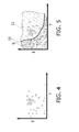
- Figure 4 is an example of the characterisation result of the "travel time” (7) - “cycle time” (8) plan as a result of a group of rivets used to create the pattern.
- the group of rivets is installed in a structure in which accessing the "unexposed” face is possible to evaluate the quality.
- For each indicated rivet its "travel time” (7) and its “cycle time” (8) is obtained, and the "unexposed face” is accessed to evaluate the quality of the installation of the rivet.
- circles (O) correspond to the positions in the "travel time” (7) - “cycle time” (8) plan of rivets the quality of which is considered “suitable”, and exes (X) correspond to the positions in the plan of rivets the quality of which is considered “unsuitable”.
- Figure 5 shows the division of the "travel time” (7) - "cycle time” (8) plan depending on the two regions defined by the suitable and the unsuitable rivets.
- the two regions are referred to as “suitable area” (11) and “unsuitable area” (9) and are separated by the border (10).
- Figure 7 shows the results of a first experiment with real time values used in the installation of each represented rivet.
- Circles (O) represent suitable rivets and exes (X) represent rivets which are considered unsuitable.
- the x-axis represents "travel time” in microseconds ( ⁇ s) and the y-axis represents "cycle time” in seconds (s).
- Figure 8 shows the results of a second experiment with real time values used in the installation of each represented rivet.
- Circles (O) represent suitable rivets and exes (X) represent rivets which are considered unsuitable.
- the x-axis represents the "travel time” in microseconds ( ⁇ s) and the y-axis represents "cycle time” in seconds (s).
- the "cycle time” is defined as the time elapsed between the opening of pneumatic valves of the machine used to perform the riveting and the instant the stem (1) of the rivet breaks. This data is obtained by means of external sensors or other similar means.
- the "cycle time" is provided by a numerical control which the machine installing the rivet incorporates.
- the "travel time” is measured by the pulse-echo method where the receiver is the same sound wave generator.
- the system for creating a time relation pattern comprises:
- the system for installing and evaluating blind rivets comprises
Landscapes
- Physics & Mathematics (AREA)
- Analytical Chemistry (AREA)
- General Health & Medical Sciences (AREA)
- Health & Medical Sciences (AREA)
- Life Sciences & Earth Sciences (AREA)
- Chemical & Material Sciences (AREA)
- Pathology (AREA)
- Biochemistry (AREA)
- Immunology (AREA)
- General Physics & Mathematics (AREA)
- Mechanical Engineering (AREA)
- Engineering & Computer Science (AREA)
- Acoustics & Sound (AREA)
- Insertion Pins And Rivets (AREA)
- Testing Of Devices, Machine Parts, Or Other Structures Thereof (AREA)
Abstract
Description
- The present invention relates to a method and system for evaluating the installation of blind rivets used in attaching structures, a system and method for generating a pattern relating installation "cycle time" and "travel time", and an aircraft comprising a structure installed with the systems described above.
- Blind rivets are widely used in closed aeronautical structures, where attachments have very restricted access on one of the sides, with no possibility of accessing or even viewing the rear part of the attachment. Consequently, the rivet quality evaluation process is carried out exclusively from the access face ('exposed face').
- Blind rivets are inserted in the corresponding holes, and the riveting process is carried out until the stem of the rivet breaks, the rivet being installed. However, since accessing the blind face (or unexposed face) is not possible, it is not possible to carry out a complete quality control of the attachment.
- There is no absolute assurance that the inspection method supplied by rivet manufacturers detects faults inside the rivet or in its closing head (unexposed face) when the choice of rivet is not suitable according to the thickness of the attachment, reaching a critical situation when the thickness is close to the limit between two lengths of the rivet.
- Although the process parameters leading to the correct installation of rivets are known in the vast majority of installations, and despite the current control methods, a significant number of attachments are still produced in which the rivets are incorrectly installed. Consequently, the attachments designed by means of blind rivets must be oversized, increasing the number of necessary rivets, manufacturing times, weight and cost of the resulting attachments. Furthermore, the existing methods based exclusively on monitoring the process do not contemplate errors due to machining steps after the riveting itself, such as machining the mandrel, a necessary operation in aeronautical applications for meeting the aerodynamics requirements.
- A system which, in a non-destructive way, informs of the correct installation of rivets, it is necessary to assure the correct installation of the rivets with maximum assurance.
- Until now methods for inspecting the state of the rivet have been proposed. Most of the proposed methods are based on monitoring the riveting process. These methods are based on measuring one or several signals during the riveting process and subsequent analysis thereof, either for comparing with standard curves or for extracting evaluation values which are subsequently compared with reference values. Some of the existing methods based on monitoring the process are listed below. First, document
US5666710A describes monitoring the "force" and "displacement" signals and the evaluation value is the energy invested in the riveting process. In patentUS7313851B2 the same signals are monitored but the evaluation value is an instant comparison with the standard curve characterising installation processes. DocumentWO2007028218A1 describes monitoring the torsion angle in the rivet. - These methods based exclusively on monitoring the process do not contemplate errors due to machining steps after the riveting itself, which steps are necessary in constructing riveted structures and can induce defects in the rivets.
- Unlike methods based on monitoring the riveting process, the method proposed in
GB2425179 - The main technical problem which the invention solves is that of finding a technical solution to the contactless evaluation of blind rivets installed in closed structures or structures for which it is complicated or costly to access the "unexposed face", based on the analysis of the riveting step and the subsequent evaluation for immediately classifying the rivet as suitable or unsuitable.
- The present invention solves the problem described above by means of a non-invasive method for evaluating the installation of a blind rivet used in attaching structures according to
claim 1, a system for installing blind rivets in structures according toclaim 7, a method for generating a pattern relating "cycle time" with "travel time" according to claim 9, a system for generating a pattern according toclaim 10, a system for installing and evaluating the installation of blind rivets according toclaim 11 and an aircraft according toclaim 12. - The invention relates to a non-invasive method for evaluating the installation of a blind rivet used in attaching structures, where the blind rivet comprises a stem, an installation nut, a break notch, cut-off points and a bushing, characterised by comprising the steps of:
- a) measuring the "cycle time" defined as the installation time of the rivet which is installed and represented as "y0",
- The installation "cycle time", which is the time elapsing from the start of a riveting operation until the end of the operation, is measured during the installation of a blind rivet. The cycle time is obtained as the time elapsed between an event representing the start of the installation cycle and an event representing the end of the cycle. This time is represented as "y0".
- b) transmitting sound waves through the blind rivet installed in the structure,
- The sound is a mechanical vibration which is propagated in materials. A generator generates the sound waves and they are transmitted through the installed blind rivet.
- c) measuring the "travel time" defined as the propagation time of the transmitted and reflected sound wave, and represented as "x0",
- Sound waves are only propagated through a material means, therefore when a wave reaches the boundary of the material in which it is being propagated it cannot continue to advance and is reflected. If there is another material in the boundary, part of the wave is propagated in the second material and part is reflected in the first material. The fact that sound is transmitted and reflected allows it to be used to find out some physical properties of the material in which they are propagated. The "travel time" measurement is directly related to the length of the stem of the rivet after its complete installation, including the machining of the stem if the application so requires. This time is represented as "x0".
- The receiver receives the sound waves which are reflected at the end of the travel through the installed blind rivet. The total time from the transmission of the wave through the installed blind rivet and the reception of the reflected sound wave is called "travel time".
- d) relating the "travel time" and the "cycle time", and obtaining a pair of times (x0,y0),
- The comparison of the "travel time" and "cycle time" magnitudes allows drawing up a "travel time - cycle time" plan on which to represent the pair (x0, y0).
- e) providing a time relation pattern establishing a borderline, or border, in a graphic representation the coordinates of which are (travel time, cycle time) or (x, y), between an area of suitable rivets and an area of unsuitable rivets, where the border is represented as y=f(x), such that
- for cycle time values greater than y=f(x), it is considered a "suitable area",
- for cycle time values less than y=f(x), it is considered an "unsuitable area";
- A characterising pattern of installation "cycle time" and "travel time" is provided in this step. The pattern is a border separating two areas in a graph of coordinates (x, y). An area, the "suitable area", corresponds to pairs (x, y) for rivets the installations of which are "suitable", and the other area, "the unsuitable area", corresponds to pairs (x, y) of rivets the installations of which are "unsuitable".
- f) representing the pair (x0, y0) in the graphic representation and verifying if the value of y0 is greater or less than the value of y=f(x0),
- The time relation value of the installed rivet (x0,y0) is compared with the time relation pattern in this step, obtaining a position in the plan in which to represent the installation performed. Depending on the position of (x0, y0), there will be a point located above or below the border y=f(x), these areas corresponding with the "suitable area" and the "unsuitable area".
- g) classifying the installation of the rivet as suitable or unsuitable according to the verification, such that
- if y0>f (x0) then it is considered a suitable installation
- if y0<f (x0) then it is considered an unsuitable installation;
- Depending on the position in the plan where the performed installation (x0, y0) is represented, the installation is immediately classified as suitable or unsuitable. In other words, if the representation of the installation is located in the area of the "suitable area" plan (x, y), the installation is considered "suitable", and if it is located outside this area, the installation is considered "unsuitable".
- As can be seen, the method of the invention is an alternative method to the state of the art, with a different approach, which is based on analysing the riveting step (during the process) and analysing information of the end result (after riveting). The contrast of the information obtained with a pattern according to the method proposed in the present invention is an instant and reliable tool for classifying blind rivets.
- In a second inventive aspect, a system is presented for installing blind rivets in structures implementing the method described above and comprising a riveting machine with means for measuring the "cycle time" and a sound wave transmitter with means for injecting said sound waves in an installed rivet and means for measuring the "travel time".
- In a third inventive aspect, a method is presented for creating a time relation pattern relating "cycle time" with "travel time", characterised in that it comprises the steps of:
- providing a set of rivets to install and a structure in which it is possible to verify the quality of the installed rivet,
- installing each rivet in the structure and measuring for each one the "cycle time" represented as yp, with p= A..B, where yA is the minimum "cycle time" that can be implemented for installing a rivet, and yB is the maximum "cycle time" that can be implemented,
- This time the cycle time to create the pattern is represented as yp. In the installation of rivets, it is necessary that at least one time is used to install them. This time is represented as yA and defines the minimum time necessary to install a blind rivet. It is likewise physically necessary for there to be a maximum cycle or installation time and this time is represented as yB.
- once each rivet is installed, measuring the "travel time" and representing it as xp, with p= A..B, where xA is the minimum "travel time" that can be implemented for installing a rivet, and xB is the maximum "travel time" that can be implemented;
- The travel time to create the pattern is represented as xp. In installed rivets, it is physically necessary for this time to be greater than a minimum represented as xA and it defines the minimum travel time of a sound wave and its reflection through the installed blind rivet. Given the finite length of the installed rivet, there is a maximum length for which a maximum travel time, xB, is associated.
- verifying the quality of the installation of each rivet,
- representing "travel time" and "cycle time" for each installation of each rivet in a graph with coordinates (x, y) and marking each installation as "suitable" or "unsuitable" according to the quality of the installation of each rivet,
- plotting a border y=f (x), x ∈ [xA, xB], and ∈ [yA, yB] representing values of "yp=f(xp)" above which the installations are considered "suitable" and below which the installations are considered "unsuitable", therefore, there are two areas, "suitable area" and "unsuitable area", separated by the border y=f(x).
- For the graphic representation of the times of the installed rivet, the xp, yp values thereof are considered and are represented in a graph of coordinates (x, y). According to the quality of the installed rivet which has been evaluated since it has been installed in a structure in which accessing the "unexposed" face is possible, it is marked as "suitable installation" or "unsuitable installation". The quality level of each installation is determined depending on the user implementing the method. Once the cycle and travel times of the rivets of the set have been represented, those rivets the installations of which are "suitable" are grouped in a region called "suitable area" and the rivets the installations of which are "unsuitable" are grouped in a region called "unsuitable area". These regions are divided by a border. Dividing the plan in regions, as well as the quality level associated with each region, is performed depending on a user and the quality requirements considered by the user. The regions can be determined as regions in which the quality level of the installation of the contained rivets is predominantly the same. There can even be regions of uncertainty, for example the borders, in which there is no associated quality level, and the rivets in said areas do not have associated quality level.
- In a fourth inventive aspect, a system is presented for creating a time relation pattern characterised in that it comprises:
- a set of blind rivets,
- a structure in which it is possible to verify the quality of an installed rivet,
- a system for installing blind rivets according to the second inventive aspect,
- means of viewing the quality of an installed rivet,
- processing means comprising data capture means suitable for receiving and relating "cycle time" and "travel time" of each installation of each rivet and for marking each installation as "suitable" or "unsuitable" according to the quality of the installation of each rivet,
- processing means suitable for generating a "cycle time"=f("travel time") relation determining a "suitable area" comprising the "suitable" installations in a graphic representation of "cycle time"-"travel time" and an "unsuitable area",
- output means for providing the result, this result being the "cycle time"=f("travel time") relation,
and characterised in that it implements the steps of a method according to the third inventive aspect. - In a fifth inventive aspect, a system is presented for installing and evaluating blind rivets comprising
- a system for installation according to the second inventive aspect,
- a system providing a pattern according to the fourth inventive aspect,
- means of viewing the result of the quality of an installed blind rivet, this quality being "suitable" or "unsuitable", and characterised in that it implements the steps of a method according to the first inventive aspect.
- Lastly, in a sixth inventive aspect, an aircraft is presented comprising at least one rivet installed by a system for installing and evaluating blind rivets like that of the fifth inventive aspect.
- All the technical features described in this specification (including the claims, description and drawings) can be changed in any combination, except the combinations of such mutually excluding features.
- These and other features and advantages of the invention will become more evident from the following detailed description of preferred embodiments, given only by way of illustrative and non-limiting example, in reference to the attached figures.
-
Figure 1 shows a pull-through blind rivet with a countersunk head. -
Figure 2 shows an installed pull-through blind rivet with a countersunk head. -
Figure 3 shows a sound wave transmitter on the countersunk head of a rivet. -
Figure 4 shows an example of the characterisation result of the "travel time - cycle time" plan. -
Figure 5 shows the division of the "travel time - cycle time" plan by the border determining the area of suitable and unsuitable installations. -
Figure 6 shows the "travel time - cycle time" plan already characterised, and the method for evaluating a rivet to be evaluated. -
Figure 7 shows a graph of a first actual experiment where the cycle time is represented on the y-axis in seconds and the travel time on the x-axis in microseconds. -
Figure 8 shows a graph of a second actual experiment where the cycle time is represented on the y-axis in seconds and the travel time on the x-axis in microseconds. - The present invention relates to a method for evaluating the installation of a blind rivet used in attaching closed structures or structures for which it is complicated or costly to access the "unexposed face" for verifying whether or not the rivets have been correctly installed. An example of a blind rivet is depicted in
Figure 1 . A pull-through blind rivet with a countersunk head can be seen in this figure. It shows the different parts of a rivet: stem (1), installation nut (2), break notch (3), cut-off points (4) and bushing (5).Figure 2 shows the rivet ofFigure 1 installed in a structure where the bushing (5) is folded and can be seen abutting with the structure to prevent the rivet from coming out. The length of the rivet is represented as less than inFigure 1 due to the breaking of the stem (1). - In one embodiment, the non-invasive method for evaluating the installation of a blind rivet used in attaching structures, where the blind rivet comprises a stem (1), an installation nut (2), a break notch (3), cut-off points (4) and a bushing (5), comprises the steps of:
- a) measuring the "cycle time" (8) defined as the installation time of the rivet which is installed and represented as "y0",
- b) transmitting sound waves through the blind rivet installed in the structure,
- c) measuring the "travel time" (7) defined as the propagation time of the transmitted and reflected sound wave, and represented as "x0",
- d) relating the "travel time" and the "cycle time", and obtaining a pair of times (x0, y0),
- e) providing a time relation pattern establishing a borderline in a graphic representation the coordinates of which are (travel time, cycle time) or (x, y) between an area of suitable rivets and an area of unsuitable rivets, where the border is represented as y=f(x), such that
• for cycle time values greater than y=f(x), it is considered a "suitable area",
• for cycle time values less than y=f(x), it is considered an "unsuitable area", - f) representing the pair (x0, y0) in the graphic representation and verifying if the value of y0 is greater or less than the value of y=f (x0),
- g) classifying the installation of the rivet as suitable or unsuitable according to the verification, such that
- if y0>f (x0) then it is considered a suitable installation
- if y0<f (x0) then it is considered an unsuitable installation.
- In one embodiment, the sound waves transmitted in step b) of the method for evaluating the installation of the rivet are ultrasounds, i.e., frequency thereof exceeds 20 KHz. This feature provides the method with discretion since the human ear is not capable of perceiving sounds at this frequency. In a particular embodiment, the frequency of the sound waves used is 20 MHz.
- For measuring the "travel time" correctly a suitable frequency must be used, and to that end the precision of such measurement is greater with high frequencies. However, the attenuation of the sound wave is greater when the frequency is high, and in turn, if the frequency is too high the wave can completely attenuate and it would not be possible to measure the travel time. Therefore, a compromise between precision and attenuation is necessary. Ultrasound waves in the 20 MHz frequency are advantageously used, thereby measuring the "travel time" with sufficient precision.
- In one embodiment, the system for installing blind rivets comprises:
- a riveting machine with means for measuring the "cycle time" of the installation, and
- a sound wave transmitter (6) comprising:
- means for transmitting sound waves,
- means of injecting the waves into a rivet and
- means for measuring the "travel time".
- In one embodiment of the system, ultrasound waves at 20 MHz are used and a 20 MHz ultrasound wave generator-transmitter (6) is used. As can be seen in
Figure 3 , the same sound wave generator-transmitter (6) is used as emitter-transmitter and receiver generating ultrasound waves and receiving the reflected waves, placing it on the installed rivet for injecting the ultrasound wave at 20 MHz into the rivet and thus being able to measure the "travel time". - In one embodiment of the system, the machine which installs the rivet incorporates a numerical control suitable for measuring the "cycle time".
- In one embodiment, the method for creating a time relation pattern relating "cycle time" with "travel time" comprises the steps of:
- providing a set of rivets to install and a structure in which it is possible to verify the quality of the installed rivet,
- installing each rivet in the structure and measuring for each one the "cycle time" represented as yp, with p= A..B, where yA is the minimum "cycle time" that can be implemented for installing a rivet, and yB is the maximum "cycle time" that can be implemented,
- once each rivet is installed, measuring the "travel time" and representing it as xp, with p= A..B, where xA is the minimum "travel time" that can be implemented for installing a rivet, and xB is the maximum "travel time" that can be implemented,
- verifying the quality of the installation of each rivet,
- representing "travel time" and "cycle time" for each installation of each rivet in a graph with coordinates (x, y) and marking each installation as "suitable" or "unsuitable" according to the quality of the installation of each rivet,
- plotting a border y=f (x), x ∈ [xA, xB], and ∈ [yA, yB], representing values of "yp=f (xp)" above which the installations are considered "suitable" and below which the installations are considered "unsuitable", therefore, there are two areas, "suitable area" and "unsuitable area", separated by the border y=f(x).
- The method for creating a pattern generates a graphic representation of "suitable" and "unsuitable" installations based on the "travel time" and the "cycle time" as well as a border y=f(x) determining two regions: "suitable area" and "unsuitable area".
-
Figure 4 is an example of the characterisation result of the "travel time" (7) - "cycle time" (8) plan as a result of a group of rivets used to create the pattern. The group of rivets is installed in a structure in which accessing the "unexposed" face is possible to evaluate the quality. For each indicated rivet, its "travel time" (7) and its "cycle time" (8) is obtained, and the "unexposed face" is accessed to evaluate the quality of the installation of the rivet. A technician decides which quality level is acceptable inspecting the installed rivets and represents the rivets in the plan ofFigure 4 , circles (O) correspond to the positions in the "travel time" (7) - "cycle time" (8) plan of rivets the quality of which is considered "suitable", and exes (X) correspond to the positions in the plan of rivets the quality of which is considered "unsuitable". -
Figure 5 shows the division of the "travel time" (7) - "cycle time" (8) plan depending on the two regions defined by the suitable and the unsuitable rivets. The two regions are referred to as "suitable area" (11) and "unsuitable area" (9) and are separated by the border (10). The border corresponds to the relation y=f (x) and represents values of "yp=f (xp)" above which the installations are considered "suitable" and below which the installations are considered "unsuitable", therefore, there are two areas, "suitable area" and "unsuitable area", separated by the border y=f(x). -
Figure 6 shows the "travel time" (7) - "cycle time" (8) plan of an already installed rivet, and the method for evaluating the rivet to be evaluated (14). Given the "travel time of the rivet to be evaluated" (12), or x0, and the "cycle time of the rivet to be evaluated" (13), or y0, the position (14) of the rivet to be evaluated corresponds to the "unsuitable area" (9) since it is seen that y=f(x0)>y0, and the installation of the rivet is therefore classified as "unsuitable". -
Figure 7 shows the results of a first experiment with real time values used in the installation of each represented rivet. Circles (O) represent suitable rivets and exes (X) represent rivets which are considered unsuitable. In the graph, the x-axis represents "travel time" in microseconds (µs) and the y-axis represents "cycle time" in seconds (s). Some of the values of the following table (Table 1) are represented in the graph ofFigure 7 . "M" represents unsuitable installations and "B" represents suitable installations:Table 1 Installation Travel time (µs) Cycle time (s) M 3.92 2.76 M 3.98 2.61 M 3.95 2.82 M 3.92 2.72 M 3.96 2.84 M 3.92 2.73 M 3.81 2.99 M 3.93 2.66 M 3.98 2.87 M 3.92 2.67 M 3.91 2.81 M 3.86 2.86 M 3.94 2.99 M 4.08 2.57 M 3.94 2.73 M 3.94 2.78 M 3.85 2.84 B 4.37 2.94 B 4.29 2.82 B 4.34 2.76 B 4.33 2.80 B 4.31 2.70 B 4.35 2.79 B 4.43 2.85 B 4.36 2.75 B 0.03 1.27 B 4.30 2.89 B 4.33 2.80 B 4.33 2.77 B 4.43 2.92 B 4.42 2.84 B 4.40 3.01 B 4.32 2.93 B 4.28 2.87 B 4.39 2.80 M 3.90 2.87 M 3.94 2.77 M 3.96 2.68 M 3.92 2.73 M 3.91 2.80 M 3.87 2.73 M 4.38 2.24 M 3.97 2.60 M 3.95 2.67 B 4.32 2.83 B 4.31 2.80 M 3.98 2.68 M 3.92 2.83 M 3.90 2.71 M 3.90 2.68 M 3.95 2.66 B 4.41 2.98 B 4.30 3.06 B 4.47 2.92 B 4.30 2.94 B 4.27 2.85 B 4.32 2.88 B 4.32 2.92 B 4.40 2.92 B 4.29 2.90 B 4.24 2.98 B 4.36 2.91 B 4.36 2.70 -
Figure 8 shows the results of a second experiment with real time values used in the installation of each represented rivet. Circles (O) represent suitable rivets and exes (X) represent rivets which are considered unsuitable. In the graph, the x-axis represents the "travel time" in microseconds (µs) and the y-axis represents "cycle time" in seconds (s). Some of the values of the following table (Table 2) are represented in the graph ofFigure 8 . "M" represents unsuitable installations and "B" represents suitable installations:Table 2 Installation Travel time (µs) Cycle time (s) M 3.49 2.86 M 3.53 2.97 M 3.48 2.86 B 3.91 3.01 B 3.79 3.23 B 3.82 2.96 M 3.64 2.79 M 3.68 2.62 M 3.79 2.50 M 3.90 2.50 M 3.67 2.74 M 3.59 2.75 M 3.63 2.74 M 3.67 2.73 M 3.88 2.52 M 3.52 2.79 M 3.69 2.74 B 3.90 2.93 B 3.76 3.31 B 3.81 2.87 B 3.77 2.94 B 3.81 2.85 B 3.72 2.99 B 3.88 2.88 B 3.77 3.02 B 3.80 2.83 B 3.84 2.84 B 3.89 2.75 M 3.64 2.74 M 3.75 2.82 M 3.75 2.54 M 3.71 2.72 M 3.80 2.46 M 3.91 2.41 M 3.67 2.71 M 3.80 2.51 M 3.72 2.79 M 3.41 3.00 M 3.64 2.77 M 3.45 2.70 M 3.65 2.71 M 3.92 2.35 M 3.81 2.63 M 3.42 2.74 M 3.42 2.93 M 3.40 2.75 M 3.45 2.86 M 3.47 2.69 M 3.45 2.70 B 3.75 3.00 B 3.71 3.05 B 3.76 2.92 B 3.67 3.03 B 3.74 3.02 B 3.66 3.15 B 3.82 2.82 B 3.74 3.12 B 3.69 3.09 B 3.75 3.06 B 3.74 2.93 B 3.64 3.07 B 3.73 3.04 B 3.86 3.05 - In one embodiment of the method, the "cycle time" is defined as the time elapsed between the opening of pneumatic valves of the machine used to perform the riveting and the instant the stem (1) of the rivet breaks. This data is obtained by means of external sensors or other similar means.
- In one embodiment of the method, the "cycle time" is provided by a numerical control which the machine installing the rivet incorporates.
- In one embodiment of the method for creating a time relation pattern, the "travel time" is measured by the pulse-echo method where the receiver is the same sound wave generator. System for creating a time relation pattern
- In one embodiment, the system for creating a time relation pattern comprises:
- a set of blind rivets,
- a structure in which it is possible to verify the quality of an installed rivet,
- a system for installing blind rivets according to the second inventive aspect or any of the embodiments thereof described above,
- means of viewing the quality of an installed rivet,
- processing means comprising data capture means suitable for receiving and representing "cycle time" and "travel time" of each installation of each rivet in a graph and for marking each installation as "suitable" or "unsuitable" according to the quality of the installation of each rivet,
- processing means suitable for generating a "cycle time"=f("travel time") relation determining a "suitable area" comprising the "suitable" installations in a graphic representation of "cycle time"-"travel time" a nd an "unsuitable area",
- output means for providing the result, this result being the "cycle time"=f("travel time") relation,
wherein the system for creating a time relation pattern it implements the steps of the non-invasive method for evaluating the installation of a blind rivet according to the first inventive aspect or any of the embodiments thereof described above. - In one embodiment, the system for installing and evaluating blind rivets comprises
- a system for installing blind rivets according to the first inventive aspect or any of the embodiments thereof described above,
- a system for creating a pattern according to the fourth inventive aspect or any of the embodiments thereof described above,
- means of viewing the result of the quality of a blind rivet, this quality being "suitable" or "unsuitable",
Claims (12)
- A non-invasive method for evaluating the installation of a blind rivet used in attaching structures, where the blind rivet comprises a stem (1), an installation nut (2), a break notch (3), cut-off points (4) and a bushing (5), characterised in that it comprises the steps of:a) measuring the "cycle time" (8) defined as the installation time of the rivet which is installed and represented as "y0",b) transmitting sound waves through the blind rivet installed in the structure,c) measuring the "travel time" (7) defined as the propagation time of the transmitted and reflected sound wave, and represented as "x0",d) relating the "travel time" and the "cycle time", and obtaining a pair of times (x0, y0),e) providing a time relation pattern establishing a borderline in a graphic representation the coordinates of which are (travel time, cycle time) or (x, y) between an area of suitable rivets and an area of unsuitable rivets, where the border is represented as y=f(x), such that
• for cycle time values greater than y=f(x), it is considered a "suitable area",
• for cycle time values less than y=f(x), it is considered an "unsuitable area",f) representing the pair (x0, y0) in the graphic representation and verifying if the value of y0 is greater or less than the value of y=f(x0),g) classifying the installation of the rivet as suitable or unsuitable according to the verification, such that
• if y0>f (x0) then it is considered a suitable installation
• if y0<f(x0) then it is considered an unsuitable installation. - The method according to claim 1, wherein the sound waves are ultrasounds.
- The method according to claim 2, wherein the frequency of the sound wave is 20 MHZ.
- The method according to any of the preceding claims, where the "cycle time" is obtained as the time elapsed between the opening of pneumatic valves of a machine used to install the rivet and the instant the stem of the rivet breaks.
- The method according to any of the preceding claims, where the "cycle time" is provided by a numerical control of the machine used to install the rivet.
- The method according to any of the preceding claims, wherein the "travel time" is measured by a pulse-echo method in which the receiver is the same generator-transmitter generating and transmitting the sound waves.
- A system for installing blind rivets, characterised in that it comprises:• a riveting machine with means for measuring the installation "cycle time",• a transmitter (6) with means for transmitting sound waves, means of injecting the waves into a rivet and means for measuring the "travel time".
- The system according to claim 7, characterised in that the sound waves are ultrasound waves at 20 MHz.
- A method for creating a time relation pattern relating "cycle time" with "travel time", characterised in that it comprises the steps of:• providing a set of rivets to install and a structure in which it is possible to verify the quality of the rivet installed,• installing each rivet in the structure and measuring for each one the "cycle time" represented as yp, with p= A..B, where yA is the minimum "cycle time" that can be implemented for installing a rivet, and yB is the maximum "cycle time" that can be implemented,• once each rivet is installed, measuring the "travel time" and representing it as xp, with p= A..B, where xA is the minimum "travel time" that can be implemented for installing a rivet, and xB is the maximum "travel time" that can be implemented,• verifying the quality of the installation of each rivet,• representing "travel time" and "cycle time" for each installation of each rivet in a graph with coordinates (x, y) and marking each installation as "suitable" or "unsuitable" according to the quality of the installation of each rivet,• plotting a border y=f (x), x ∈ [xA, xB], and ∈ [yA, yB], representing values of "yp=f (xp) " above which the installations are considered "suitable" and below which the installations are considered "unsuitable", therefore, there are two areas, "suitable area" and "unsuitable area", separated by the border y=f(x).
- A system for creating a time relation pattern, characterised in that it comprises:• a set of blind rivets,• a structure in which it is possible to verify the quality of an installed rivet,• a system for installing blind rivets according to claim 7,• means of viewing the quality of an installed rivet,• processing means comprising data capture means suitable for receiving and representing "cycle time" and "travel time" of each installation of each rivet in a graph and for marking each installation as "suitable" or "unsuitable" according to the quality of the installation of each rivet,• processing means suitable for generating a "cycle time"=f("travel time") relation determining a "suitable area" comprising the "suitable" installations in a graphic representation of "cycle time"-"travel time" and an "unsuitable area",• output means for providing the result, this result being the "cycle time"=f("travel time") relation,
and characterised in that it implements the steps of a method according to claim 8. - A system for installing and evaluating blind rivets, characterised in that it comprises
• a system for installing according to claim 7,
• a system providing a pattern according to claim 9,
• means of viewing the result of the quality of a blind rivet, this quality being "suitable" or "unsuitable",
and characterised in that it implements the steps of a non-invasive method for evaluating the installation of a blind rivet according to any of claims 1 to 6. - An aircraft comprising at least one structure installed by means of a system according to claim 11.
Priority Applications (3)
| Application Number | Priority Date | Filing Date | Title |
|---|---|---|---|
| EP12382106.8A EP2641672A1 (en) | 2012-03-23 | 2012-03-23 | Method for evaluating the installation of blind rivets, method and system for installing blind rivets, method and system for obtaining a pattern, and aircraft |
| US13/828,815 US9766210B2 (en) | 2012-03-23 | 2013-03-14 | Method for evaluating the installation of blind rivets, method and system for installing blind rivets, method and system for obtaining a pattern, and aircraft |
| CN201310095305.0A CN103317076B (en) | 2012-03-23 | 2013-03-22 | Blind rivet installation and evaluating and modeling method thereof, corresponding system and aircraft |
Applications Claiming Priority (1)
| Application Number | Priority Date | Filing Date | Title |
|---|---|---|---|
| EP12382106.8A EP2641672A1 (en) | 2012-03-23 | 2012-03-23 | Method for evaluating the installation of blind rivets, method and system for installing blind rivets, method and system for obtaining a pattern, and aircraft |
Publications (1)
| Publication Number | Publication Date |
|---|---|
| EP2641672A1 true EP2641672A1 (en) | 2013-09-25 |
Family
ID=46262057
Family Applications (1)
| Application Number | Title | Priority Date | Filing Date |
|---|---|---|---|
| EP12382106.8A Withdrawn EP2641672A1 (en) | 2012-03-23 | 2012-03-23 | Method for evaluating the installation of blind rivets, method and system for installing blind rivets, method and system for obtaining a pattern, and aircraft |
Country Status (3)
| Country | Link |
|---|---|
| US (1) | US9766210B2 (en) |
| EP (1) | EP2641672A1 (en) |
| CN (1) | CN103317076B (en) |
Cited By (1)
| Publication number | Priority date | Publication date | Assignee | Title |
|---|---|---|---|---|
| EP2869068A1 (en) * | 2013-10-31 | 2015-05-06 | Rigas Tehniska Universitate | Method for ultrasonic testing of bolted and riveted joints in structures |
Families Citing this family (3)
| Publication number | Priority date | Publication date | Assignee | Title |
|---|---|---|---|---|
| DE102010035613A1 (en) * | 2010-08-26 | 2012-03-01 | Heiko Schmidt | Method and tool for setting blind rivet elements |
| JP7031362B2 (en) * | 2018-02-23 | 2022-03-08 | トヨタ自動車株式会社 | Blind rivet fastening device |
| CN110788224B (en) * | 2019-10-16 | 2021-04-13 | 昆明理工大学 | A quality inspection method for imprinted connection points |
Citations (4)
| Publication number | Priority date | Publication date | Assignee | Title |
|---|---|---|---|---|
| US5666710A (en) | 1995-04-20 | 1997-09-16 | Emhart Inc. | Blind rivet setting system and method for setting a blind rivet then verifying the correctness of the set |
| GB2425179A (en) | 2005-04-14 | 2006-10-18 | Warwickshire Mfg Group | Assessing the quality of rivets by evaluating the complex valued electrical impedance of a piezoelectric ultrasonic transducer |
| WO2007028218A1 (en) | 2005-09-05 | 2007-03-15 | Rubens Cioto | Method for attaining a predetermined clamping force in trheaded joints |
| US7313851B2 (en) | 2006-01-27 | 2008-01-01 | Gm Global Technology Operations, Inc. | Method for monitoring the installation of blind rivets |
Family Cites Families (15)
| Publication number | Priority date | Publication date | Assignee | Title |
|---|---|---|---|---|
| US3292413A (en) * | 1963-10-21 | 1966-12-20 | Boeing Co | Riveting apparatus |
| US4201093A (en) * | 1978-07-20 | 1980-05-06 | Metriguard, Inc. | Ultrasonic sheet material testing apparatus |
| US4901431A (en) * | 1988-06-06 | 1990-02-20 | Textron Inc. | Powered fastener installation apparatus |
| US5035353A (en) * | 1989-12-01 | 1991-07-30 | Emhart Inc. | Automatic riveting machine |
| US5343785A (en) * | 1991-10-23 | 1994-09-06 | Emerson Electric Co. | Ultrasonic bolting control apparatus |
| US5600878A (en) | 1995-04-20 | 1997-02-11 | Emhart Inc. | Mandrel stem length measurement system for use with blind rivet setting tool |
| US5661887A (en) * | 1995-04-20 | 1997-09-02 | Emhart Inc. | Blind rivet set verification system and method |
| US6314817B1 (en) * | 1998-05-14 | 2001-11-13 | Atlas Copco Tools Ab | Method for tightening a threaded fastener above its yield point |
| CZ305122B6 (en) | 2002-01-21 | 2015-05-13 | MS Gerätebau GmbH | Insertion tool and method of checking insertion processes for such a tool |
| GB2390833B (en) * | 2002-07-18 | 2005-09-14 | Emhart Llc | Method and apparatus for monitoring blind fastener setting |
| EP1750868A1 (en) | 2004-03-24 | 2007-02-14 | Newfrey LLC | A rivet monitoring system |
| WO2006014675A1 (en) * | 2004-07-19 | 2006-02-09 | Newfrey Llc | Blind rivet monitoring system supply pressure compensation |
| US7555833B2 (en) * | 2005-04-14 | 2009-07-07 | Gm Global Technology Operations, Inc. | System for programmable self-piercing riveting |
| US7791254B1 (en) * | 2006-11-27 | 2010-09-07 | William Gordon Gibson | Hybrid ultrasound transducer |
| ES2331290B1 (en) | 2008-06-27 | 2010-09-29 | Airbus Operations, S.L. | MULTIFUNCTION DEVICE AND AUTOMATIC TRAFFICKING PROCEDURE BY NUMERICAL CONTROL. |
-
2012
- 2012-03-23 EP EP12382106.8A patent/EP2641672A1/en not_active Withdrawn
-
2013
- 2013-03-14 US US13/828,815 patent/US9766210B2/en not_active Expired - Fee Related
- 2013-03-22 CN CN201310095305.0A patent/CN103317076B/en not_active Expired - Fee Related
Patent Citations (4)
| Publication number | Priority date | Publication date | Assignee | Title |
|---|---|---|---|---|
| US5666710A (en) | 1995-04-20 | 1997-09-16 | Emhart Inc. | Blind rivet setting system and method for setting a blind rivet then verifying the correctness of the set |
| GB2425179A (en) | 2005-04-14 | 2006-10-18 | Warwickshire Mfg Group | Assessing the quality of rivets by evaluating the complex valued electrical impedance of a piezoelectric ultrasonic transducer |
| WO2007028218A1 (en) | 2005-09-05 | 2007-03-15 | Rubens Cioto | Method for attaining a predetermined clamping force in trheaded joints |
| US7313851B2 (en) | 2006-01-27 | 2008-01-01 | Gm Global Technology Operations, Inc. | Method for monitoring the installation of blind rivets |
Cited By (1)
| Publication number | Priority date | Publication date | Assignee | Title |
|---|---|---|---|---|
| EP2869068A1 (en) * | 2013-10-31 | 2015-05-06 | Rigas Tehniska Universitate | Method for ultrasonic testing of bolted and riveted joints in structures |
Also Published As
| Publication number | Publication date |
|---|---|
| US9766210B2 (en) | 2017-09-19 |
| US20130250730A1 (en) | 2013-09-26 |
| CN103317076B (en) | 2017-04-26 |
| CN103317076A (en) | 2013-09-25 |
Similar Documents
| Publication | Publication Date | Title |
|---|---|---|
| CA2977148C (en) | Wrinkle characterization and performance prediction for composite structures | |
| Raghavan et al. | Guided-wave signal processing using chirplet matching pursuits and mode correlation for structural health monitoring | |
| Hong et al. | Uncertainty quantification for acoustic nonlinearity parameter in Lamb wave-based prediction of barely visible impact damage in composites | |
| EP2924427A1 (en) | Method and apparatus for quantifying porosity in a component | |
| EP1751535B1 (en) | Method and device for determining defects in a turbine blade with an ultrasonic phased array | |
| CN109387567B (en) | Additive manufacturing laser ultrasonic detection data processing method based on wave speed correction | |
| CN103529121B (en) | Composite material laminated board machine adds bore edges pulse reflection method lamination defect analogy method | |
| US9766210B2 (en) | Method for evaluating the installation of blind rivets, method and system for installing blind rivets, method and system for obtaining a pattern, and aircraft | |
| EP2269051B1 (en) | Imaging an anomaly using backscattered waves | |
| CN107917957B (en) | A kind of damage detection method of plate structure | |
| US10843821B2 (en) | Predictive preparation of material for joint assembly | |
| CN105572229B (en) | Method for verifying the calibration of a non-destructive testing system for components and assembly | |
| CN108151870B (en) | Construction quality problem detection method based on frequency response function | |
| DE102016224988A1 (en) | Method and device for detecting defects in an object | |
| EP3794342B1 (en) | Method for adjusting and calibrating testing devices for ultrasonic testing of workpieces | |
| DE102018131948B4 (en) | Method and device for detecting an impact event and a vehicle for this purpose | |
| US7434468B2 (en) | Porosity reference standard for ultrasonic inspection of composite materials | |
| EP2090886A2 (en) | Method for optimising the voltage distribution in acoustic thermography applications | |
| US7366627B2 (en) | Method for satisfying certification requirements and verifying the integrity of structural health management systems | |
| Harding et al. | Model-assisted probability of detection validation of automated ultrasonic scanning for crack detection at fastener holes | |
| US9671372B2 (en) | Method and device for ascertaining an edge layer characteristic of a component | |
| US10794873B2 (en) | Signal processing for ultrasound imaging systems | |
| Rickli et al. | Damage detection in assembly fixtures using non-destructive electromechanical impedance sensors and multivariate statistics | |
| Thompson et al. | Uses for model-based probability of detection curves | |
| CN119989155A (en) | Automated production and intelligent detection methods for aircraft engine case forgings |
Legal Events
| Date | Code | Title | Description |
|---|---|---|---|
| PUAI | Public reference made under article 153(3) epc to a published international application that has entered the european phase |
Free format text: ORIGINAL CODE: 0009012 |
|
| AK | Designated contracting states |
Kind code of ref document: A1 Designated state(s): AL AT BE BG CH CY CZ DE DK EE ES FI FR GB GR HR HU IE IS IT LI LT LU LV MC MK MT NL NO PL PT RO RS SE SI SK SM TR |
|
| AX | Request for extension of the european patent |
Extension state: BA ME |
|
| 17P | Request for examination filed |
Effective date: 20140321 |
|
| RBV | Designated contracting states (corrected) |
Designated state(s): AL AT BE BG CH CY CZ DE DK EE ES FI FR GB GR HR HU IE IS IT LI LT LU LV MC MK MT NL NO PL PT RO RS SE SI SK SM TR |
|
| 17Q | First examination report despatched |
Effective date: 20160226 |
|
| GRAP | Despatch of communication of intention to grant a patent |
Free format text: ORIGINAL CODE: EPIDOSNIGR1 |
|
| INTG | Intention to grant announced |
Effective date: 20170719 |
|
| RIN1 | Information on inventor provided before grant (corrected) |
Inventor name: RIVERO RASTRERO, MARIA ASUNCION Inventor name: SAENZ FERNANDEZ, AGUSTIN Inventor name: CAMACHO DE MIGUEL, JAVIER Inventor name: ASTORGA RAMIREZ, JUAN RAMON Inventor name: GUZMAN RABANILLO, DESIREE |
|
| GRAS | Grant fee paid |
Free format text: ORIGINAL CODE: EPIDOSNIGR3 |
|
| GRAJ | Information related to disapproval of communication of intention to grant by the applicant or resumption of examination proceedings by the epo deleted |
Free format text: ORIGINAL CODE: EPIDOSDIGR1 |
|
| GRAL | Information related to payment of fee for publishing/printing deleted |
Free format text: ORIGINAL CODE: EPIDOSDIGR3 |
|
| GRAP | Despatch of communication of intention to grant a patent |
Free format text: ORIGINAL CODE: EPIDOSNIGR1 |
|
| INTC | Intention to grant announced (deleted) | ||
| INTG | Intention to grant announced |
Effective date: 20180105 |
|
| STAA | Information on the status of an ep patent application or granted ep patent |
Free format text: STATUS: THE APPLICATION IS DEEMED TO BE WITHDRAWN |
|
| 18D | Application deemed to be withdrawn |
Effective date: 20180516 |