EP2640174A2 - Electronic device and sealed structure - Google Patents
Electronic device and sealed structure Download PDFInfo
- Publication number
- EP2640174A2 EP2640174A2 EP12198482.7A EP12198482A EP2640174A2 EP 2640174 A2 EP2640174 A2 EP 2640174A2 EP 12198482 A EP12198482 A EP 12198482A EP 2640174 A2 EP2640174 A2 EP 2640174A2
- Authority
- EP
- European Patent Office
- Prior art keywords
- housing member
- opening
- electronic device
- housed
- sealing member
- Prior art date
- Legal status (The legal status is an assumption and is not a legal conclusion. Google has not performed a legal analysis and makes no representation as to the accuracy of the status listed.)
- Withdrawn
Links
Images







Classifications
-
- H—ELECTRICITY
- H05—ELECTRIC TECHNIQUES NOT OTHERWISE PROVIDED FOR
- H05K—PRINTED CIRCUITS; CASINGS OR CONSTRUCTIONAL DETAILS OF ELECTRIC APPARATUS; MANUFACTURE OF ASSEMBLAGES OF ELECTRICAL COMPONENTS
- H05K5/00—Casings, cabinets or drawers for electric apparatus
- H05K5/06—Hermetically-sealed casings
- H05K5/069—Other details of the casing, e.g. wall structure, passage for a connector, a cable, a shaft
-
- H—ELECTRICITY
- H05—ELECTRIC TECHNIQUES NOT OTHERWISE PROVIDED FOR
- H05K—PRINTED CIRCUITS; CASINGS OR CONSTRUCTIONAL DETAILS OF ELECTRIC APPARATUS; MANUFACTURE OF ASSEMBLAGES OF ELECTRICAL COMPONENTS
- H05K5/00—Casings, cabinets or drawers for electric apparatus
- H05K5/06—Hermetically-sealed casings
- H05K5/061—Hermetically-sealed casings sealed by a gasket held between a removable cover and a body, e.g. O-ring, packing
-
- H—ELECTRICITY
- H04—ELECTRIC COMMUNICATION TECHNIQUE
- H04M—TELEPHONIC COMMUNICATION
- H04M1/00—Substation equipment, e.g. for use by subscribers
- H04M1/02—Constructional features of telephone sets
- H04M1/0202—Portable telephone sets, e.g. cordless phones, mobile phones or bar type handsets
- H04M1/026—Details of the structure or mounting of specific components
-
- H—ELECTRICITY
- H04—ELECTRIC COMMUNICATION TECHNIQUE
- H04M—TELEPHONIC COMMUNICATION
- H04M1/00—Substation equipment, e.g. for use by subscribers
- H04M1/02—Constructional features of telephone sets
- H04M1/18—Telephone sets specially adapted for use in ships, mines, or other places exposed to adverse environment
-
- H—ELECTRICITY
- H05—ELECTRIC TECHNIQUES NOT OTHERWISE PROVIDED FOR
- H05K—PRINTED CIRCUITS; CASINGS OR CONSTRUCTIONAL DETAILS OF ELECTRIC APPARATUS; MANUFACTURE OF ASSEMBLAGES OF ELECTRICAL COMPONENTS
- H05K5/00—Casings, cabinets or drawers for electric apparatus
- H05K5/06—Hermetically-sealed casings
- H05K5/062—Hermetically-sealed casings sealed by a material injected between a non-removable cover and a body, e.g. hardening in situ
-
- H—ELECTRICITY
- H04—ELECTRIC COMMUNICATION TECHNIQUE
- H04M—TELEPHONIC COMMUNICATION
- H04M1/00—Substation equipment, e.g. for use by subscribers
- H04M1/02—Constructional features of telephone sets
- H04M1/0202—Portable telephone sets, e.g. cordless phones, mobile phones or bar type handsets
- H04M1/026—Details of the structure or mounting of specific components
- H04M1/0262—Details of the structure or mounting of specific components for a battery compartment
-
- Y—GENERAL TAGGING OF NEW TECHNOLOGICAL DEVELOPMENTS; GENERAL TAGGING OF CROSS-SECTIONAL TECHNOLOGIES SPANNING OVER SEVERAL SECTIONS OF THE IPC; TECHNICAL SUBJECTS COVERED BY FORMER USPC CROSS-REFERENCE ART COLLECTIONS [XRACs] AND DIGESTS
- Y10—TECHNICAL SUBJECTS COVERED BY FORMER USPC
- Y10T—TECHNICAL SUBJECTS COVERED BY FORMER US CLASSIFICATION
- Y10T428/00—Stock material or miscellaneous articles
- Y10T428/13—Hollow or container type article [e.g., tube, vase, etc.]
Definitions
- the embodiment discussed herein is related to an electronic device and a sealed structure.
- one side of a housing is integrated with a packing member by insert molding or two-color molding; and by pressing the other side of the housing to apply pressure to the packing member, fluids can be prevented from entering the electronic device from seams where surfaces of the housing sides meet (see, for example, Japanese Laid-Open Patent Publication No. 2011-119960 ).
- an electronic device includes a first housing member having an opening that houses a housed object; a second housing member that is mated with the first housing member; a cover member that covers the opening; and a sealing member that is integrated with the first housing member by two-color molding, seals a seam between a perimeter of the opening of the first housing member and the cover member as well as a seam between the first housing member and the second housing member, and contacts side surfaces of the housed object when the housed object is housed in the opening.
- the electronic device and sealed structure enable a reduction in electronic device size and further enable cost reductions of the electronic device to be realized.
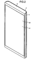
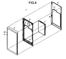
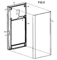
- FIGs. 1 to 5 are diagrams depicting an electronic device according to an embodiment.
- FIG. 1 is a front view
- FIG. 2 is a perspective view as viewed from the front
- FIG. 3 is a perspective view as viewed from the rear
- FIG. 4 is an exploded perspective view
- FIG. 5 is a perspective view as viewed from the same angle in FIG. 3 and a state in which a cover member has been removed from the electronic device.
- an electronic device 1 includes a first housing member 2, a sealing member 3, a second housing member 5, a cover member 6, and a housed object 7.
- the first housing member 2 has an opening 4 in which the housed object 7 is housed.
- the first housing member 2 and the second housing member 5 are mated, the housed object 7 is housed in the opening 4, and the opening 4 is sealed by the cover member 6.
- the sealing member 3 prevents substances such as water, vapors, and fine particles that are undesirable from the perspective of the electronic device 1, from entering the electronic device 1.
- the first housing member 2 is attached to the first housing member 2 by, for example, multiple screws 8. The screws are not depicted in the exploded perspective view depicted in FIG. 4 .
- multiple protrusions 9 are disposed on the cover member 6, while multiple grooves 10 are disposed in the first housing member 2.
- the cover member 6 is attached to the first housing member 2 by, for example, fitting each of the protrusions 9 into a corresponding groove 10.
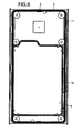
- FIGs. 6 to 9 are diagrams depicting the first housing member integrated with the sealing member.
- FIG. 6 is a front view
- FIG. 7 is a rear view
- FIG. 8 is a perspective view as viewed from the front
- FIG. 9 is a perspective view as viewed from the rear.
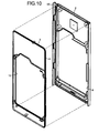
- FIG. 10 is a perspective view independently depicting the sealing member and the first housing member depicted in FIG. 8 .
- the sealing member 3 is integrated with the first housing member 2 by insert molding.
- the sealing member 3 has a first ring unit 11 and a second ring unit 12 (also refer to FIGs. 11 to 14 ).
- the first ring unit 11 is shaped to follow an outer edge of the first housing member 2, and in the example depicted, is of a shape that is substantially rectangular.
- the first ring unit 11 is formed along the outer edge of the first housing member 2, in a convex section 13 (refer to FIG. 10 ) that is for forming the sealing member and that is disposed along an outer edge of the first housing member 2.
- the second ring unit 12 is shaped to follow an inner edge of the opening 4, e.g., in the example depicted, is of a shape that is substantially rectangular.
- the second ring unit 12 is disposed along the inner edge of the opening 4.
- FIGs. 11 to 14 diagrams of the sealing member.
- FIG. 11 is a front view
- FIG. 12 is a rear view
- FIG. 13 is a side view
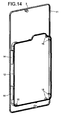
- FIG. 14 is a perspective view as viewed from the rear.
- the first ring unit 11 and the second ring unit 12 are coupled by a coupler 14.
- the second ring unit 12 for example, may be formed as a band-shape having a dimension of depth that is oriented parallel to the depth of the opening 4.
- the band-shaped portion of the second ring unit 12 may be fixed to an inner surface of the opening 4 by insert molding.
- multiple projections 15 facing inward are disposed on the second ring unit 12.
- the projections 15 are formed to contact a side surface of the housed object 7.
- the projections 15 may be formed such that each of the 4 side surfaces of the housed object 7 are contacted at, for example, 2 sites.
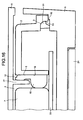
- FIG. 15 is a cross-sectional view at line A-A depicted in FIG. 1 .
- FIG. 16 is a cross-sectional view at line B-B depicted in FIG. 1 .
- the first ring unit 11 of the sealing member 3 contacts a receiving section 16 disposed along the outer edge of the second housing member 5, at a site facing the convex section 13 for forming the sealing member, whereby the seam between the first housing member 2 and the second housing member 5 is sealed.
- a protruding process 17 may be disposed on a back side of the cover member 6 (refer also to FIG. 4 ).
- the protruding process 17 is disposed on the cover member 6, at a site that faces an inner surface 18 of the opening 4.
- the second ring unit 12 of the sealing member 3 is sandwiched between the protruding process 17 and the inner surface 18 of the opening 4, and contacts both the protruding process 17 and the inner surface 18 of the opening 4.
- the seam between the perimeter of the opening 4 disposed in the first housing member 2 and the cover member 6 is sealed.
- the projections 15 of the sealing member 3 contact side surfaces of the housed object 7 housed in the opening 4, whereby the housed object 7 is supported stably in the opening 4, for example, from 4 directions.
- the shape of portions of the projections 15 contacting the side surfaces of the housed object 7 may be curved as depicted in the example or may be planar.
- Configuration may be such that rather than the sealing member 3 partially contacting side surfaces of the housed object 7 via the projections 15, the second ring unit 12 of the sealing member 3 contacts the housed object 7 along the entire perimeter or along substantially the entire perimeter of the side surfaces of the housed object 7.
- the second ring unit 12 in FIG. 5 , reference numeral 12 is omitted
- the sealing member 3 may contact substantially the entire perimeter of the side surfaces of the housed object 7.
- a mobile telephone device or a smartphone may be given as one example of the electronic device 1.
- an example of an application to a smartphone will be described.
- the second housing member 5 may be a front case.
- a display panel 20 and a touch panel 21 may be disposed at a front side of the front case.
- a circuit board 22 may be housed at a back side of the front case.
- the first housing member 2, for example, may be a rear case.
- the cover member 6, for example, may be a rear cover.
- the front case, the rear case, and the rear cover may be members made of a hard resin such as acrylonitrile-butadiene-styrene (ABS) resin and polycarbonate resin and molded from a metal mold, or may be members made of a metal such as aluminum.
- ABS acrylonitrile-butadiene-styrene
- the sealing member 3 may be a member made of a soft resin such as polyester elastomer, styrene elastomer, and olefin elastomer.
- the housed object 7 may be, for example, a battery.
- the sealing member 3 seals the second housing member 5 to the first housing member 2 and further seals the cover member 6 that covers the opening 4 of the first housing member 2, whereby the number of sealing members can be reduced compared to using separate sealing members. Therefore, the size of the electronic device 1 can be reduced. Further, cost reduction of the electronic device 1 can be realized.
- the second ring unit 12 of the sealing member 3 contacts the battery housed in the smartphone and thereby, suppresses slack in the housing of the battery, the shock resistance of the battery can be improved. Therefore, even if the smartphone is subject to external forces consequent to, for example, vibrations and dropping of the smartphone, damage to the battery can be prevented.
- the electronic device 1 is not limited to a smartphone.
- the electronic device 1 may be an electronic device having a structure in which housing members as well as a cover member covering an opening are sealed by a sealing member, such as in mobile information terminals including mobile telephones, computers and personal digital assistants (PDAs), and various types of measuring instruments.
- the housed object 7 is not limited to a battery.
- the housed object may be, for example, an apparatus that must be shock resistant such as a hard disk drive apparatus.
Landscapes
- Engineering & Computer Science (AREA)
- Microelectronics & Electronic Packaging (AREA)
- Signal Processing (AREA)
- Casings For Electric Apparatus (AREA)
- Telephone Set Structure (AREA)
- Injection Moulding Of Plastics Or The Like (AREA)
Abstract
Description
- The embodiment discussed herein is related to an electronic device and a sealed structure.
- Conventionally, as a sealed structure for an electronic device, one side of a housing is integrated with a packing member by insert molding or two-color molding; and by pressing the other side of the housing to apply pressure to the packing member, fluids can be prevented from entering the electronic device from seams where surfaces of the housing sides meet (see, for example, Japanese Laid-Open Patent Publication No.
2011-119960 - Nonetheless, with the conventional sealed structure, a problem arises in that a packing member is also necessary to prevent fluids from seeping through at the edges of a cover of an opening for housing the battery, disposed in the housing and therefore, the number of packing members increases, increasing the size of the electronic device and inviting increased cost.
- It is an object in one aspect of the embodiments to at least solve the above problems in the conventional technologies.
- According to an aspect of an embodiment, an electronic device includes a first housing member having an opening that houses a housed object; a second housing member that is mated with the first housing member; a cover member that covers the opening; and a sealing member that is integrated with the first housing member by two-color molding, seals a seam between a perimeter of the opening of the first housing member and the cover member as well as a seam between the first housing member and the second housing member, and contacts side surfaces of the housed object when the housed object is housed in the opening.
- The electronic device and sealed structure enable a reduction in electronic device size and further enable cost reductions of the electronic device to be realized.
-
-
FIG. 1 is a front view of an electronic device according to an embodiment; -
FIG. 2 is a perspective view of the electronic device as viewed from the front; -
FIG. 3 is a perspective view of the electronic device as viewed from the rear; -
FIG. 4 is an exploded perspective view of the electronic device; -
FIG. 5 is a perspective view of the electronic device as viewed from the same angle inFIG. 3 and depicts a state in which a cover member has been removed from the electronic device; -
FIG. 6 is a front view of a first housing member integrated with a sealing member; -
FIG. 7 is a rear view of the first housing member integrated with the sealing member; -
FIG. 8 is a perspective view as viewed from the front; -
FIG. 9 is a perspective view of the first housing member integrated with the sealing member as viewed from the rear; -
FIG. 10 is a perspective view independently depicting the sealing member and the first housing member depicted inFIG. 8 ; -
FIG. 11 is a front view of the sealing member; -
FIG. 12 is a rear view of the sealing member; -
FIG. 13 is a side view of the sealing member; -
FIG. 14 is a perspective view of the sealing member as viewed from the rear; -
FIG. 15 is a cross-sectional view at line A-A depicted inFIG. 1 ; and -
FIG. 16 is a cross-sectional view at line B-B depicted inFIG. 1 . - Preferred embodiments of the present invention will be explained with reference to the accompanying drawings.
-
FIGs. 1 to 5 are diagrams depicting an electronic device according to an embodiment.FIG. 1 is a front view;FIG. 2 is a perspective view as viewed from the front;FIG. 3 is a perspective view as viewed from the rear;FIG. 4 is an exploded perspective view; andFIG. 5 is a perspective view as viewed from the same angle inFIG. 3 and a state in which a cover member has been removed from the electronic device. - As depicted in
FIGs. 1 to 5 , anelectronic device 1 includes afirst housing member 2, a sealingmember 3, asecond housing member 5, acover member 6, and ahoused object 7. Thefirst housing member 2 has anopening 4 in which thehoused object 7 is housed. In theelectronic device 1, thefirst housing member 2 and thesecond housing member 5 are mated, thehoused object 7 is housed in theopening 4, and theopening 4 is sealed by thecover member 6. The sealingmember 3 prevents substances such as water, vapors, and fine particles that are undesirable from the perspective of theelectronic device 1, from entering theelectronic device 1. - The
first housing member 2 is attached to thefirst housing member 2 by, for example,multiple screws 8. The screws are not depicted in the exploded perspective view depicted inFIG. 4 . For example,multiple protrusions 9 are disposed on thecover member 6, whilemultiple grooves 10 are disposed in thefirst housing member 2. Thecover member 6 is attached to thefirst housing member 2 by, for example, fitting each of theprotrusions 9 into acorresponding groove 10. -
FIGs. 6 to 9 are diagrams depicting the first housing member integrated with the sealing member.FIG. 6 is a front view;FIG. 7 is a rear view;FIG. 8 is a perspective view as viewed from the front; andFIG. 9 is a perspective view as viewed from the rear.FIG. 10 is a perspective view independently depicting the sealing member and the first housing member depicted inFIG. 8 . - As depicted in
FIGs. 6 to 10 , the sealingmember 3 is integrated with thefirst housing member 2 by insert molding. The sealingmember 3 has afirst ring unit 11 and a second ring unit 12 (also refer toFIGs. 11 to 14 ). - The
first ring unit 11 is shaped to follow an outer edge of thefirst housing member 2, and in the example depicted, is of a shape that is substantially rectangular. Thefirst ring unit 11 is formed along the outer edge of thefirst housing member 2, in a convex section 13 (refer toFIG. 10 ) that is for forming the sealing member and that is disposed along an outer edge of thefirst housing member 2. - The
second ring unit 12 is shaped to follow an inner edge of the opening 4, e.g., in the example depicted, is of a shape that is substantially rectangular. Thesecond ring unit 12 is disposed along the inner edge of the opening 4. -
FIGs. 11 to 14 diagrams of the sealing member.FIG. 11 is a front view;FIG. 12 is a rear view;FIG. 13 is a side view; andFIG. 14 is a perspective view as viewed from the rear. - As depicted in
FIGs. 11 to 14 , in the sealingmember 3, thefirst ring unit 11 and thesecond ring unit 12 are coupled by acoupler 14. Thesecond ring unit 12, for example, may be formed as a band-shape having a dimension of depth that is oriented parallel to the depth of theopening 4. The band-shaped portion of thesecond ring unit 12 may be fixed to an inner surface of the opening 4 by insert molding. - For example,
multiple projections 15 facing inward are disposed on thesecond ring unit 12. Theprojections 15 are formed to contact a side surface of thehoused object 7. As depicted in the example, theprojections 15 may be formed such that each of the 4 side surfaces of thehoused object 7 are contacted at, for example, 2 sites. - The sealed structure will be described.
FIG. 15 is a cross-sectional view at line A-A depicted inFIG. 1 .FIG. 16 is a cross-sectional view at line B-B depicted inFIG. 1 . As depicted inFIGs. 15 and16 , thefirst ring unit 11 of the sealingmember 3 contacts a receivingsection 16 disposed along the outer edge of thesecond housing member 5, at a site facing theconvex section 13 for forming the sealing member, whereby the seam between thefirst housing member 2 and thesecond housing member 5 is sealed. - A
protruding process 17 may be disposed on a back side of the cover member 6 (refer also toFIG. 4 ). Theprotruding process 17 is disposed on thecover member 6, at a site that faces aninner surface 18 of theopening 4. Thesecond ring unit 12 of the sealingmember 3 is sandwiched between theprotruding process 17 and theinner surface 18 of theopening 4, and contacts both theprotruding process 17 and theinner surface 18 of theopening 4. Thus, the seam between the perimeter of theopening 4 disposed in thefirst housing member 2 and thecover member 6 is sealed. - The
projections 15 of the sealingmember 3 contact side surfaces of thehoused object 7 housed in theopening 4, whereby thehoused object 7 is supported stably in theopening 4, for example, from 4 directions. The shape of portions of theprojections 15 contacting the side surfaces of thehoused object 7 may be curved as depicted in the example or may be planar. - Configuration may be such that rather than the sealing
member 3 partially contacting side surfaces of the housedobject 7 via theprojections 15, thesecond ring unit 12 of the sealingmember 3 contacts the housedobject 7 along the entire perimeter or along substantially the entire perimeter of the side surfaces of the housedobject 7. For example, as in the example depicted inFIG. 5 , excluding aconvex section 19 providing finger access to a side surface of the housedobject 7 in the removal of the housedobject 7 from thefirst housing member 2, the second ring unit 12 (inFIG. 5 ,reference numeral 12 is omitted) of the sealingmember 3 may contact substantially the entire perimeter of the side surfaces of the housedobject 7. - A mobile telephone device or a smartphone may be given as one example of the
electronic device 1. Here, an example of an application to a smartphone will be described. - In the case of application to a smartphone, the
second housing member 5, for example, may be a front case. As depicted inFIGs. 1 ,2 ,4 ,15 , and16 , at a front side of the front case, adisplay panel 20 and atouch panel 21 may be disposed. Further, at a back side of the front case, acircuit board 22 may be housed. - The
first housing member 2, for example, may be a rear case. Thecover member 6, for example, may be a rear cover. The front case, the rear case, and the rear cover may be members made of a hard resin such as acrylonitrile-butadiene-styrene (ABS) resin and polycarbonate resin and molded from a metal mold, or may be members made of a metal such as aluminum. - The sealing
member 3 may be a member made of a soft resin such as polyester elastomer, styrene elastomer, and olefin elastomer. The housedobject 7 may be, for example, a battery. - According to the embodiment, the sealing
member 3 seals thesecond housing member 5 to thefirst housing member 2 and further seals thecover member 6 that covers theopening 4 of thefirst housing member 2, whereby the number of sealing members can be reduced compared to using separate sealing members. Therefore, the size of theelectronic device 1 can be reduced. Further, cost reduction of theelectronic device 1 can be realized. - Further, for example, in a smartphone, since the
second ring unit 12 of the sealingmember 3 contacts the battery housed in the smartphone and thereby, suppresses slack in the housing of the battery, the shock resistance of the battery can be improved. Therefore, even if the smartphone is subject to external forces consequent to, for example, vibrations and dropping of the smartphone, damage to the battery can be prevented. - The
electronic device 1 is not limited to a smartphone. Theelectronic device 1 may be an electronic device having a structure in which housing members as well as a cover member covering an opening are sealed by a sealing member, such as in mobile information terminals including mobile telephones, computers and personal digital assistants (PDAs), and various types of measuring instruments. Further, the housedobject 7 is not limited to a battery. The housed object may be, for example, an apparatus that must be shock resistant such as a hard disk drive apparatus. - All examples and conditional language provided herein are intended for pedagogical purposes of aiding the reader in understanding the invention and the concepts contributed by the inventor to further the art, and are not to be construed as limitations to such specifically recited examples and conditions, nor does the organization of such examples in the specification relate to a showing of the superiority and inferiority of the invention. Although one or more embodiments of the present invention have been described in detail, it should be understood that the various changes, substitutions, and alterations could be made hereto without departing from the spirit and scope of the invention.
Claims (6)
- An electronic device (1) comprising:a first housing member (2) having an opening that houses a housed object;a second housing member (5) that is mated with the first housing member (2);a cover member (6) that covers the opening; anda sealing member (3) that is integrated with the first housing member (2) by two-color molding, seals a seam between a perimeter of the opening of the first housing member (2) and the cover member (6) as well as a seam between the first housing member (2) and the second housing member (5), and contacts side surfaces of the housed object when the housed object is housed in the opening.
- The electronic device (1) according to claim 1, wherein the sealing member (3) partially contacts the side surfaces of the housed object, at multiple sites.
- The electronic device (1) according to claim 1 or 2, wherein the sealing member (3) can contact the sides of the housed object along an entire perimeter or along substantially the entire perimeter of the side surfaces of the housed object.
- A sealed structure, wherein
a seam between a first housing member (2) and a second housing member (5) mated with the first housing member (2) as well as a seam between a perimeter of an opening disposed in the first housing member (2) and a cover member (6) covering the opening are sealed by a sealing member (3), and
the sealing member (3) contacts side surfaces of a housed object housed in the opening. - The sealed structure according to claim 4, wherein the sealing member (3) partially contacts the side surfaces of the housed object, at multiple sites.
- The sealed structure according to claim 4 or 5, wherein the sealing member (3) contacts the side surfaces of the housed object along an entire perimeter or along substantially the entire perimeter of the side surfaces.
Applications Claiming Priority (1)
| Application Number | Priority Date | Filing Date | Title |
|---|---|---|---|
| JP2012059713A JP5857819B2 (en) | 2012-03-16 | 2012-03-16 | Electronics |
Publications (2)
| Publication Number | Publication Date |
|---|---|
| EP2640174A2 true EP2640174A2 (en) | 2013-09-18 |
| EP2640174A3 EP2640174A3 (en) | 2017-04-05 |
Family
ID=47665823
Family Applications (1)
| Application Number | Title | Priority Date | Filing Date |
|---|---|---|---|
| EP12198482.7A Withdrawn EP2640174A3 (en) | 2012-03-16 | 2012-12-20 | Electronic device and sealed structure |
Country Status (4)
| Country | Link |
|---|---|
| US (1) | US9338910B2 (en) |
| EP (1) | EP2640174A3 (en) |
| JP (1) | JP5857819B2 (en) |
| CN (1) | CN103313563B (en) |
Cited By (4)
| Publication number | Priority date | Publication date | Assignee | Title |
|---|---|---|---|---|
| US9051465B1 (en) | 2012-02-21 | 2015-06-09 | Park Electrochemical Corporation | Thermosetting resin composition containing a polyphenylene ether and a brominated fire retardant compound |
| US9243164B1 (en) | 2012-02-21 | 2016-01-26 | Park Electrochemical Corporation | Thermosetting resin composition containing a polyphenylene ether and a brominated fire retardant compound |
| EP3531809A1 (en) * | 2018-02-27 | 2019-08-28 | Amazonen-Werke H. Dreyer GmbH & Co. KG | Device for sealing a recess in an object |
| EP3576178A4 (en) * | 2017-01-26 | 2021-04-21 | Samsung SDI Co., Ltd. | BATTERY PACK |
Families Citing this family (13)
| Publication number | Priority date | Publication date | Assignee | Title |
|---|---|---|---|---|
| JP6051103B2 (en) * | 2013-05-23 | 2016-12-27 | 富士通株式会社 | Waterproof structure and electronic equipment |
| US10148000B2 (en) | 2015-09-04 | 2018-12-04 | Apple Inc. | Coupling structures for electronic device housings |
| WO2017059116A1 (en) | 2015-09-30 | 2017-04-06 | Apple Inc. | Multi-part electronic device housing having contiguous filled surface |
| DE102015015707A1 (en) * | 2015-12-07 | 2017-06-08 | Testo SE & Co. KGaA | Housing for an electronic device and modular system for a housing |
| US10372166B2 (en) | 2016-07-15 | 2019-08-06 | Apple Inc. | Coupling structures for electronic device housings |
| JP6950796B2 (en) * | 2017-10-05 | 2021-10-13 | カシオ計算機株式会社 | Battery module manufacturing method |
| CN108243587B (en) * | 2018-02-05 | 2020-01-14 | Oppo广东移动通信有限公司 | Middle frame assembly, middle frame assembly machining method and electronic device |
| KR102642314B1 (en) * | 2018-12-06 | 2024-03-04 | 삼성전자주식회사 | Electronic device having waterproof structure |
| US11632448B2 (en) | 2019-12-03 | 2023-04-18 | Apple Inc. | Handheld electronic device |
| US11784673B2 (en) | 2020-09-16 | 2023-10-10 | Apple Inc. | Electronic device housing having a radio-frequency transmissive component |
| US11769940B2 (en) | 2021-09-09 | 2023-09-26 | Apple Inc. | Electronic device housing with integrated antenna |
| US12388168B2 (en) | 2021-09-23 | 2025-08-12 | Apple Inc. | Portable electronic device having integrated antenna elements |
| US12581003B2 (en) | 2022-01-10 | 2026-03-17 | Apple Inc. | Handheld electronic device |
Citations (1)
| Publication number | Priority date | Publication date | Assignee | Title |
|---|---|---|---|---|
| JP2011119960A (en) | 2009-12-03 | 2011-06-16 | Fujitsu Toshiba Mobile Communications Ltd | Electronic device |
Family Cites Families (11)
| Publication number | Priority date | Publication date | Assignee | Title |
|---|---|---|---|---|
| US5363276A (en) * | 1993-09-01 | 1994-11-08 | Ncr Corporation | Apparatus for containing and supporting electronic components |
| JP3156494B2 (en) * | 1994-04-01 | 2001-04-16 | セイコーエプソン株式会社 | Digital Multimeters |
| JPH08250866A (en) * | 1995-03-09 | 1996-09-27 | Kokusai Electric Co Ltd | Case structure for small devices |
| JP2007312255A (en) * | 2006-05-19 | 2007-11-29 | Casio Hitachi Mobile Communications Co Ltd | Waterproof structure for battery compartment and battery pack in electronic equipment |
| KR100810266B1 (en) * | 2006-12-14 | 2008-03-06 | 삼성전자주식회사 | Portable terminal with reinforcing member |
| KR101441568B1 (en) * | 2008-01-11 | 2014-09-25 | 삼성디스플레이 주식회사 | Display device and its assembling method |
| CN101626673A (en) * | 2009-05-31 | 2010-01-13 | 珠海东之尼电子科技有限公司 | Water-proof device of remote control |
| JP2011250076A (en) * | 2010-05-26 | 2011-12-08 | Kyocera Corp | Portable electronic apparatus |
| KR20120071751A (en) * | 2010-12-23 | 2012-07-03 | 엘지디스플레이 주식회사 | Display device |
| US8687351B2 (en) * | 2011-03-31 | 2014-04-01 | Patientsafe Solutions, Inc. | Scanning jacket for a handheld device |
| CN202160361U (en) * | 2011-06-20 | 2012-03-07 | 深圳富泰宏精密工业有限公司 | Front cover of electronic device and electronic device with same |
-
2012
- 2012-03-16 JP JP2012059713A patent/JP5857819B2/en active Active
- 2012-12-20 EP EP12198482.7A patent/EP2640174A3/en not_active Withdrawn
- 2012-12-22 US US13/726,108 patent/US9338910B2/en active Active
-
2013
- 2013-01-14 CN CN201310012180.0A patent/CN103313563B/en not_active Expired - Fee Related
Patent Citations (1)
| Publication number | Priority date | Publication date | Assignee | Title |
|---|---|---|---|---|
| JP2011119960A (en) | 2009-12-03 | 2011-06-16 | Fujitsu Toshiba Mobile Communications Ltd | Electronic device |
Cited By (5)
| Publication number | Priority date | Publication date | Assignee | Title |
|---|---|---|---|---|
| US9051465B1 (en) | 2012-02-21 | 2015-06-09 | Park Electrochemical Corporation | Thermosetting resin composition containing a polyphenylene ether and a brominated fire retardant compound |
| US9243164B1 (en) | 2012-02-21 | 2016-01-26 | Park Electrochemical Corporation | Thermosetting resin composition containing a polyphenylene ether and a brominated fire retardant compound |
| EP3576178A4 (en) * | 2017-01-26 | 2021-04-21 | Samsung SDI Co., Ltd. | BATTERY PACK |
| US11133553B2 (en) | 2017-01-26 | 2021-09-28 | Samsung Sdi Co., Ltd. | Battery pack |
| EP3531809A1 (en) * | 2018-02-27 | 2019-08-28 | Amazonen-Werke H. Dreyer GmbH & Co. KG | Device for sealing a recess in an object |
Also Published As
| Publication number | Publication date |
|---|---|
| US9338910B2 (en) | 2016-05-10 |
| US20130242477A1 (en) | 2013-09-19 |
| JP2013197137A (en) | 2013-09-30 |
| JP5857819B2 (en) | 2016-02-10 |
| EP2640174A3 (en) | 2017-04-05 |
| CN103313563B (en) | 2016-02-24 |
| CN103313563A (en) | 2013-09-18 |
Similar Documents
| Publication | Publication Date | Title |
|---|---|---|
| US9338910B2 (en) | Electronic device and sealed structure | |
| JP6924931B2 (en) | Electronic devices and terminal covers for electronic devices | |
| JP2018120060A (en) | Display and electronic apparatus | |
| US20140118905A1 (en) | Protective case for portable electronic device | |
| US9608243B2 (en) | Electronic device with battery terminal sealing member | |
| US8238119B2 (en) | Electronic device | |
| JPWO2013011676A1 (en) | Electronics | |
| WO2017077670A1 (en) | Electronic device | |
| CN108551013B (en) | Deck component and electronic equipment | |
| KR101590688B1 (en) | Portable electronic device, and waterproof cover | |
| KR20230148062A (en) | Electronic device including guide member for wiring | |
| CN101896042A (en) | Portable electronic device | |
| US9319500B2 (en) | Electronic device with display having reduced border region | |
| JP5880437B2 (en) | Housing for electronic equipment | |
| US20140158559A1 (en) | Protective case for portable electronic device | |
| US9094498B2 (en) | Water resistant structure and electronic apparatus | |
| JP2016076303A (en) | Electronic equipment | |
| US8254099B2 (en) | Housing of portable electronic device | |
| CN102548281B (en) | Mobile device | |
| JP5905796B2 (en) | Mobile device | |
| JP6691301B2 (en) | Electronic equipment and housing | |
| US20120111713A1 (en) | Portable electronic device and printed circuit board module | |
| CN102469185B (en) | Portable electronic apparatus having casings | |
| JP2012119709A (en) | Electronic apparatus | |
| JP6193606B2 (en) | Mobile device |
Legal Events
| Date | Code | Title | Description |
|---|---|---|---|
| PUAI | Public reference made under article 153(3) epc to a published international application that has entered the european phase |
Free format text: ORIGINAL CODE: 0009012 |
|
| AK | Designated contracting states |
Kind code of ref document: A2 Designated state(s): AL AT BE BG CH CY CZ DE DK EE ES FI FR GB GR HR HU IE IS IT LI LT LU LV MC MK MT NL NO PL PT RO RS SE SI SK SM TR |
|
| AX | Request for extension of the european patent |
Extension state: BA ME |
|
| PUAL | Search report despatched |
Free format text: ORIGINAL CODE: 0009013 |
|
| AK | Designated contracting states |
Kind code of ref document: A3 Designated state(s): AL AT BE BG CH CY CZ DE DK EE ES FI FR GB GR HR HU IE IS IT LI LT LU LV MC MK MT NL NO PL PT RO RS SE SI SK SM TR |
|
| AX | Request for extension of the european patent |
Extension state: BA ME |
|
| RIC1 | Information provided on ipc code assigned before grant |
Ipc: H05K 5/06 20060101AFI20170301BHEP Ipc: H04M 1/02 20060101ALI20170301BHEP Ipc: H04M 1/18 20060101ALI20170301BHEP |
|
| STAA | Information on the status of an ep patent application or granted ep patent |
Free format text: STATUS: REQUEST FOR EXAMINATION WAS MADE |
|
| 17P | Request for examination filed |
Effective date: 20170901 |
|
| RBV | Designated contracting states (corrected) |
Designated state(s): AL AT BE BG CH CY CZ DE DK EE ES FI FR GB GR HR HU IE IS IT LI LT LU LV MC MK MT NL NO PL PT RO RS SE SI SK SM TR |
|
| STAA | Information on the status of an ep patent application or granted ep patent |
Free format text: STATUS: EXAMINATION IS IN PROGRESS |
|
| 17Q | First examination report despatched |
Effective date: 20180613 |
|
| STAA | Information on the status of an ep patent application or granted ep patent |
Free format text: STATUS: THE APPLICATION HAS BEEN WITHDRAWN |
|
| 18W | Application withdrawn |
Effective date: 20181003 |