EP2640127A1 - Proactive Uplink Transmit Power Increase In Small Cells Upon Outbound Handovers - Google Patents
Proactive Uplink Transmit Power Increase In Small Cells Upon Outbound Handovers Download PDFInfo
- Publication number
- EP2640127A1 EP2640127A1 EP12305312.6A EP12305312A EP2640127A1 EP 2640127 A1 EP2640127 A1 EP 2640127A1 EP 12305312 A EP12305312 A EP 12305312A EP 2640127 A1 EP2640127 A1 EP 2640127A1
- Authority
- EP
- European Patent Office
- Prior art keywords
- transmit power
- mobile station
- handover
- target
- cell
- Prior art date
- Legal status (The legal status is an assumption and is not a legal conclusion. Google has not performed a legal analysis and makes no representation as to the accuracy of the status listed.)
- Granted
Links
- 238000005259 measurement Methods 0.000 claims abstract description 26
- 238000000034 method Methods 0.000 claims abstract description 23
- 238000012790 confirmation Methods 0.000 claims description 3
- 238000001514 detection method Methods 0.000 claims description 3
- 230000001960 triggered effect Effects 0.000 claims description 3
- 238000004891 communication Methods 0.000 description 19
- 230000005540 biological transmission Effects 0.000 description 14
- 230000006870 function Effects 0.000 description 5
- 238000013507 mapping Methods 0.000 description 5
- 230000007246 mechanism Effects 0.000 description 5
- 230000011664 signaling Effects 0.000 description 4
- 238000012935 Averaging Methods 0.000 description 3
- 230000008859 change Effects 0.000 description 3
- 238000005516 engineering process Methods 0.000 description 3
- 101100061276 Arabidopsis thaliana CPR5 gene Proteins 0.000 description 2
- 230000006978 adaptation Effects 0.000 description 2
- 230000001413 cellular effect Effects 0.000 description 2
- 238000010295 mobile communication Methods 0.000 description 2
- 230000035515 penetration Effects 0.000 description 2
- 230000000737 periodic effect Effects 0.000 description 2
- 230000008569 process Effects 0.000 description 2
- 238000007493 shaping process Methods 0.000 description 2
- 238000012360 testing method Methods 0.000 description 2
- 230000003466 anti-cipated effect Effects 0.000 description 1
- 238000013459 approach Methods 0.000 description 1
- 230000008878 coupling Effects 0.000 description 1
- 238000010168 coupling process Methods 0.000 description 1
- 238000005859 coupling reaction Methods 0.000 description 1
- 230000003247 decreasing effect Effects 0.000 description 1
- 238000013461 design Methods 0.000 description 1
- 230000000694 effects Effects 0.000 description 1
- 238000001914 filtration Methods 0.000 description 1
- 230000006872 improvement Effects 0.000 description 1
- 230000003993 interaction Effects 0.000 description 1
- 238000012886 linear function Methods 0.000 description 1
- 238000005457 optimization Methods 0.000 description 1
- 230000000149 penetrating effect Effects 0.000 description 1
- 238000012545 processing Methods 0.000 description 1
- 230000007420 reactivation Effects 0.000 description 1
- 230000000717 retained effect Effects 0.000 description 1
- 238000001228 spectrum Methods 0.000 description 1
- 238000013519 translation Methods 0.000 description 1
- 230000014616 translation Effects 0.000 description 1
Images



Classifications
-
- H—ELECTRICITY
- H04—ELECTRIC COMMUNICATION TECHNIQUE
- H04W—WIRELESS COMMUNICATION NETWORKS
- H04W52/00—Power management, e.g. Transmission Power Control [TPC] or power classes
- H04W52/04—Transmission power control [TPC]
- H04W52/18—TPC being performed according to specific parameters
- H04W52/24—TPC being performed according to specific parameters using SIR [Signal to Interference Ratio] or other wireless path parameters
-
- H—ELECTRICITY
- H04—ELECTRIC COMMUNICATION TECHNIQUE
- H04W—WIRELESS COMMUNICATION NETWORKS
- H04W36/00—Hand-off or reselection arrangements
- H04W36/0005—Control or signalling for completing the hand-off
- H04W36/0083—Determination of parameters used for hand-off, e.g. generation or modification of neighbour cell lists
- H04W36/0085—Hand-off measurements
-
- H—ELECTRICITY
- H04—ELECTRIC COMMUNICATION TECHNIQUE
- H04W—WIRELESS COMMUNICATION NETWORKS
- H04W36/00—Hand-off or reselection arrangements
- H04W36/0005—Control or signalling for completing the hand-off
- H04W36/0083—Determination of parameters used for hand-off, e.g. generation or modification of neighbour cell lists
- H04W36/00837—Determination of triggering parameters for hand-off
-
- H—ELECTRICITY
- H04—ELECTRIC COMMUNICATION TECHNIQUE
- H04W—WIRELESS COMMUNICATION NETWORKS
- H04W52/00—Power management, e.g. Transmission Power Control [TPC] or power classes
- H04W52/04—Transmission power control [TPC]
- H04W52/30—Transmission power control [TPC] using constraints in the total amount of available transmission power
- H04W52/36—Transmission power control [TPC] using constraints in the total amount of available transmission power with a discrete range or set of values, e.g. step size, ramping or offsets
-
- H—ELECTRICITY
- H04—ELECTRIC COMMUNICATION TECHNIQUE
- H04W—WIRELESS COMMUNICATION NETWORKS
- H04W52/00—Power management, e.g. Transmission Power Control [TPC] or power classes
- H04W52/04—Transmission power control [TPC]
- H04W52/38—TPC being performed in particular situations
- H04W52/40—TPC being performed in particular situations during macro-diversity or soft handoff
-
- H—ELECTRICITY
- H04—ELECTRIC COMMUNICATION TECHNIQUE
- H04W—WIRELESS COMMUNICATION NETWORKS
- H04W36/00—Hand-off or reselection arrangements
- H04W36/0005—Control or signalling for completing the hand-off
- H04W36/0083—Determination of parameters used for hand-off, e.g. generation or modification of neighbour cell lists
-
- H—ELECTRICITY
- H04—ELECTRIC COMMUNICATION TECHNIQUE
- H04W—WIRELESS COMMUNICATION NETWORKS
- H04W52/00—Power management, e.g. Transmission Power Control [TPC] or power classes
- H04W52/04—Transmission power control [TPC]
- H04W52/06—TPC algorithms
- H04W52/12—Outer and inner loops
-
- H—ELECTRICITY
- H04—ELECTRIC COMMUNICATION TECHNIQUE
- H04W—WIRELESS COMMUNICATION NETWORKS
- H04W52/00—Power management, e.g. Transmission Power Control [TPC] or power classes
- H04W52/04—Transmission power control [TPC]
- H04W52/06—TPC algorithms
- H04W52/14—Separate analysis of uplink or downlink
- H04W52/146—Uplink power control
-
- H—ELECTRICITY
- H04—ELECTRIC COMMUNICATION TECHNIQUE
- H04W—WIRELESS COMMUNICATION NETWORKS
- H04W52/00—Power management, e.g. Transmission Power Control [TPC] or power classes
- H04W52/04—Transmission power control [TPC]
- H04W52/18—TPC being performed according to specific parameters
- H04W52/24—TPC being performed according to specific parameters using SIR [Signal to Interference Ratio] or other wireless path parameters
- H04W52/242—TPC being performed according to specific parameters using SIR [Signal to Interference Ratio] or other wireless path parameters taking into account path loss
-
- H—ELECTRICITY
- H04—ELECTRIC COMMUNICATION TECHNIQUE
- H04W—WIRELESS COMMUNICATION NETWORKS
- H04W52/00—Power management, e.g. Transmission Power Control [TPC] or power classes
- H04W52/04—Transmission power control [TPC]
- H04W52/18—TPC being performed according to specific parameters
- H04W52/24—TPC being performed according to specific parameters using SIR [Signal to Interference Ratio] or other wireless path parameters
- H04W52/245—TPC being performed according to specific parameters using SIR [Signal to Interference Ratio] or other wireless path parameters taking into account received signal strength
-
- H—ELECTRICITY
- H04—ELECTRIC COMMUNICATION TECHNIQUE
- H04W—WIRELESS COMMUNICATION NETWORKS
- H04W52/00—Power management, e.g. Transmission Power Control [TPC] or power classes
- H04W52/04—Transmission power control [TPC]
- H04W52/30—Transmission power control [TPC] using constraints in the total amount of available transmission power
- H04W52/36—Transmission power control [TPC] using constraints in the total amount of available transmission power with a discrete range or set of values, e.g. step size, ramping or offsets
- H04W52/362—Aspects of the step size
Definitions
- the present invention relates to a method and apparatus for controlling the transmit power of a mobile station served by a small cell.
- Heterogeneous Networks are now being deployed, where cells of smaller footprint size (so-called pico, metro or micro cells) are embedded within the coverage area of larger umbrella cells (so-called macro cells), primarily to provide increased capacity in targeted areas of data traffic concentration. HetNet try to exploit the spatial variation in user and traffic distribution to efficiently increase the overall capacity of mobile networks.
- indoor data offloading has become a focus of the industry in the recent years.
- the indoor data offloading incentive is significant firstly due to the successful penetration and the maturity of the fixed broadband technology that can be re-used for mobile network backhauling, and secondly because of the substantial cellular network resources that are expended on penetrating buildings.
- One attractive solution to offload indoor users' traffic is to deploy femto cells (or home cells). Femto cells are short-range cells operated by subscriber-owned radio access points, and provides improved indoor coverage and increased throughput to home users while off-loading traffic from expensive macro radio access onto the low-cost public Internet.
- hard handover the channel in the source cell is released and only then the channel in the target cell is engaged. Thus the connection to the source is broken before the connection to the target is made. For this reason such handovers are also known as break-before-make handovers.
- soft handover is one in which the channel in the source cell is retained and used for a while in parallel with the channel in the target cell. In this case the connection to the target is established before the connection to the source is broken, hence these handovers are called make-before-break handovers.
- WCDMA Wideband Code Division Multiple Access
- the uplink inner-loop power control adjusts the User Equipment (UE) transmit power in order to keep the received uplink Signal to Noise and Interference Ratio (SNIR) on that frequency at a given SNIR target, SNIR_Target.
- the base station should estimate the SNIR SNIR_Estimate of the received uplink Dedicated Physical Control CHannel (DPCCH).
- DPCCH Dedicated Physical Control CHannel
- the base station should then generate Transmit Power Control (TPC) commands and transmit the commands once per slot (i.e., once every 0.66 ms) according to the following rule: if SNIR_Estimate > SNIR_Target then the TPC command to transmit is "0", while if SNIR_Estimate ⁇ SNIR_Target then the TPC command to transmit is "1".
- TPC Transmit Power Control
- each algorithm defines how the TPC commands ought to be interpreted and combined (when received from multiple base stations).
- algorithm 2 is more stable compared to algorithm 1 in a sense that it considers five consecutive time slots before making a judgment regarding a change of the transmit power, but is consequently slower than algorithm 1.
- the UE receives TPC commands from all the cells that it is attached to.
- the TPC combining process is very conservative in a sense that it gives precedence to the base station requiring the lowest uplink transmit power and yielding the least interference.
- the UE In hard handover, after the UE establishes its connection to the target cell, it adjusts its transmit power using the open loop power control to estimate the required transmission power for communication with the target cell.
- the UE's initial transmission consists only of the DPCCH transmission.
- the UE determines its initial DPCCH transmit power, based on the Received Signal code Power (RSCP) of the pilot channel (CPICH):
- RSCP Received Signal code Power
- CPICH pilot channel
- the test set signals a value for DPCCH_Power_offset that places the UE's initial transmission near the UE target power setting.
- the UE target power setting is the level that is set for the UE's DPCCH and Dedicated Physical Data CHannel (DPDCH) transmission.
- DPDCH Dedicated Physical Data CHannel
- the required uplink transmission power to reach the macro base station is significantly higher than the uplink power of the femto cell users. This implies that when the handover is performed, the UE needs to substantially increase its transmit power level so as to communicate with the macro cell. This abrupt and significant change of the transmit power introduces a sudden drop of the SNIR for the other femto cell user(s).
- the aforementioned closed-loop power control mechanisms assures that the other femto cell user(s) can sustain the required SNIR at the femto base station despite the changes of the radio channel such as signal fast fades due to users' mobility.
- the aforementioned algorithm 2 is used for transmit power control. Therefore, there is potentially a risk of call drops during the adaptation of the users' transmission power. Even if the call could be maintained, at least severe drop of users' QoE is expected.
- Soft handovers may be used too in future femto cells deployment.
- the UE receives TPC commands from all the cells that it is attached to.
- the TPC combining process is very conservative since it is sufficient if the user can at least communicate to one of the base stations. Again this is not a problem for traditional macro cell to macro cell handovers as the required transmission power from the edge of one cell to another cell is not varied substantially. However this is not the case when it comes to soft handovers from femto to macro cells as the user would normally need to transmit with considerably higher power to reach the macro base station.
- the TPC command coming from the femto base station during the soft handover regime would keep the user's transmission power low and therefore the user would have difficulty adapting the power quickly enough when he is fully switched to the macro cell (after the handover completes normal power control is used to adapt the transmission power of the user). Again the case is even worse if the aforementioned algorithm 2 is used for transmit power control.
- a method for controlling the transmit power of a mobile station served by a small cell comprises the steps of detecting a measurement event anticipating the forthcoming fulfillment of a handover condition towards a neighboring macro cell by the mobile station, and thereupon step-wise increasing the transmit power level of the mobile station so as to reach a transmit power target when the handover condition is eventually fulfilled by the mobile station.
- a transmit power controller for controlling the transmit power of a mobile station served by a small cell, and configured to detect a measurement event anticipating the forthcoming fulfillment of a handover condition towards a neighboring macro cell by the mobile station, and thereupon step-wise increasing the transmit power level of the mobile station so as to reach a transmit power target when the handover condition is eventually fulfilled by the mobile station.
- the transmit power controller preferably forms part of a radio access point configured to operate the small cell, such as a femto, pico, metro or micro base station.
- the handover condition is a condition whereby the macro cell is measured as being offset better than the small cell by a first positive handover offset, thereby yielding a reference receive signal strength or quality threshold in the small cell for handover towards the macro cell
- the measurement event is a measurement event whereby a current receive strength or quality level for the mobile station in the small cell was measured as being below a handover anticipation threshold which is the sum of the reference receive signal strength or quality threshold and a second positive anticipation offset.
- the transmit power target is for compensating for an estimated downlink path loss for the mobile station in the macro cell.
- the transmit power target is determined by measuring a receive signal strength of a reference pilot signal broadcast within the macro cell at a nominal downlink transmit power.
- the step-wise increase of the transmit power is a monotonically-decreasing function of a current receive strength or quality level for the mobile station in the small cell.
- the step-wise increase of the transmit power corresponds to a linear power increase from an initial transmit power used by the mobile station in the small cell when the measurement event is detected up to the transmit power target.
- the step-wise increase of the transmit power corresponds to a second or higher order polynomial power increase from an initial transmit power used by the mobile station in the small cell when the measurement event is detected up to the transmit power target.
- the increase of the transmit power level for the mobile station is withdrawn if no handover towards the macro cell took place for the mobile station during a handover confirmation time period triggered upon detection of the measurement event.
- the present invention proposes to proactively adapt the power of the small cell users which are likely to have a handover towards the macro cell soon.
- a forthcoming handover event towards a neighboring macro cell is anticipated for a particular UE served by the small cell, and the uplink transmit power level of the UE in the small cell is gradually increased in such a way that an uplink transmit power target is in force when the handover towards the macro cell eventually takes place.
- the downlink receive power/quality level in the small cell at which a handover condition towards the macro cell is fulfilled for a particular UE is known by means of UE measurement reports.
- This downlink receive power/quality level varies across UEs and from one handover location to another.
- This reference threshold can be used in combination with an anticipation offset to anticipate an upcoming handover event and to start increasing the UE transmit power before the actual handover occurrence.
- the anticipation offset and the transmit power target are designed so as to reduce the uplink transmit power disruption upon handover execution, and to enable the other small cell user(s) to gradually adapt their uplink transmit power level to cope with this interference increase and to maintain the required SNIR and hence the call quality.
- the transmit power target value is determined so as to compensate for an estimate of the downlink path loss incurred by the UE within the macro cell upon handover execution.
- the transmit power target can be determined by measuring the receive signal strength of a reference pilot signal broadcast within the macro cell at a nominal downlink transmit power.
- This pilot signal can be measured by the UE upon detection of the handover condition, thereby yielding a rather accurate measure of the downlink path loss when handover towards the macro cell takes place, and thus a rather accurate uplink transmit power target that will avoid any substantial uplink transmit power disruption when the UE eventually switches to the macro cell.
- the pilot signal can be directly measured by the small base station operating the small cell, which is a sub-optimal yet still advantageous solution.
- the transmit power increase is a function of a current receive strength or quality level for the mobile station in the small cell.
- the transmit power increase can be a linear increase or a polynomial/exponential increase from an initial uplink transmit power level up to the uplink transmit power target that is to be achieved.
- Fig. 1 illustrates a UMTS mobile network 1 making use of WCDMA radio access technology.
- a UE 11 roams through the mobile network 1.
- Macro base stations 21 are provided operating respective macro cells. A number of such base stations are provided, which are distributed geographically in order to provide a wide area of coverage to the UE 11.
- radio communication may be established with the corresponding base station operating the particular macro cell over an associated radio link conforming to the Uu communication interface.
- fig. 1 illustrates a small subset of the total number of UEs and base stations that may be present in a typical mobile communication system.
- An RNC 31 controls the operation of the base stations 22 and of the UE 11 in order to efficiently manage the wireless communication network 10.
- the RNC 31 communicates with the base stations over a backhaul communication link conforming to the Iub communication interface, and further with the UE 11 via their respective radio link.
- the RNC 31 is operable to communicate with a Core Network (CN) 41, and to route traffic via circuit-switched and packet-switched networks.
- CN Core Network
- MSC Mobile Switching Center
- the MSC then communicates with a circuit-switched network, such as a Public Switched Telephone Network (PSTN).
- PSTN Public Switched Telephone Network
- the RNC 31 communicates with a Serving General packet radio service Support Node (SGSN, not shown) over a communication link conforming to Iu-PS communication interface.
- the SGSN is further coupled to a Gateway General packet radio service Support Node (GGSN, not shown), which communicates with a packet-switch network, such as the Internet.
- GGSN Gateway General packet radio service Support Node
- femto base stations 22 each of which operates a femto cell in the vicinity of a building within which the associated femto base station is installed.
- the femto cells provide local communication coverage for a user in the vicinity of those buildings.
- the femto base stations 22 typically utilize a broadband Internet connection (e.g., xDSL, cable) for traffic backhauling.
- the femto base stations 22 communicate with a femto cell gateway 32 (FGW) via a backhaul communication link conforming to the Iuh communication interface.
- FGW femto cell gateway 32
- the femto cell gateway 32 sits between the femto base stations 22 and the CN 31, and performs the necessary translations to ensure the femto base stations 22 appear as a RNC to the MSC.
- the femto base stations 22 talk to the femto cell gateway 32, and the femto cell gateway 32 talks to the CN 31 (MSC for circuit-switched communications, SGSN for packet-switched communications).
- the femto cell gateway 32 comprises a security gateway that terminates large numbers of encrypted data connections from hundreds of thousands of femto base stations, and a signaling gateway which aggregates and validates the signaling traffic, authenticates each femto base stations and interfaces with the CN 31.
- the femto base stations 22 are low-power, low-cost, self organizing base stations that provide private or public mobile communication services in a residential or business environment.
- the femto base stations may be provided locally by customers for their own use, but are also a cost effective solution for operators to provide low-cost hot spot coverage and rural coverage.
- the transmission power of the femto base station is relatively low in order to restrict the coverage area of the femto cell to a range of tens of meters or less.
- the femto base stations have extensive auto-configuration and self-optimization capability to enable a simple plug-and-play deployment. As such, they are designed to automatically integrate themselves into an existing macro cellular wireless network.
- the femto base stations contain some functionalities traditionally provided by the RNC, such as the Radio Resource Control (RRC) functions.
- RRC Radio Resource Control
- Pico, metro or micro base stations may be provided to operate pico, metro or micro cells.
- Pico, metro or micro cells are typically provided by network operators in areas of high traffic or poor coverage.
- a femto base station 100 configured to operate a femto cell, and comprising a transmit power controller as per the present invention.
- the femto base station 100 comprises the following functional blocks:
- the network termination unit 130 is coupled to the digital base-band unit 111; the digital base-band unit 111 is coupled to the analog band-pass unit 112; the analog band-pass unit 112 is coupled to an external or internal antenna 120.
- the radio resource controller 140 and the transmit power controller 150 are coupled to the transceiver 110.
- the transmit power controller 140 is further coupled to the radio resource controller 150.
- the transceiver 110 is configured to establish and operate radio communication channels with UEs under control of the radio resource controller 150.
- the digital base-band unit 111 is for digitally processing the received and transmit data symbols.
- the digital base-band unit 111 implements the necessary protocol suites for issuing, terminating or relaying signaling packets (or control packets), and for relaying user data traffic.
- the analog band-pass unit 112 is for modulating, amplifying and shaping the transmit signal that ultimately feds the antenna 130, and for filtering, amplifying with as little noise as possible and demodulating the received signal from the antenna 130.
- the analog band-pass 112 unit can be merged with the digital base-band unit 111 into one single unit.
- the network termination unit 130 accommodates the appropriate Medium Access Control (MAC) and Physical transport (PHY) layers for connecting through a broadband connection to a femto cell gateway, as well as some frame dispatching logic for routing the incoming/outgoing frames towards the appropriate Input/output (I/O) ports.
- MAC Medium Access Control
- PHY Physical transport
- the radio resource controller 140 is for assigning and managing downlink and uplink radio resources used by the transceivers 110 and the respective UEs for radio communication over the air interface, that is to say a set of code and/or frequency resources assigned to the respective radio bearers for transport of user traffic.
- the radio resource controller 140 further configures the active UEs with a measurement policy (see “meas_policy(UEX)" in fig. 2 ).
- the UEs are configured to periodically report measurements of the serving and neighboring cells (see “meas_report(UEX)” in fig. 2 ).
- the measurement report typically comprises Ec/No measurements performed on the Primary Common PIlot CHannel (P-CPICH) of the serving and neighboring cells.
- Ec/No stands for the received energy per chip divided by the power density in the band, and is equal to the Received Signal Code Power (RSCP) measurements, meaning the received power on one code measured on the P-CPICH of the serving or neighboring cell, divided by the received wide band power, including thermal noise and noise generated in the receiver, within the bandwidth defined by the receiver pulse shaping filter.
- RSCP Received Signal Code Power
- the radio resource controller 140 compares the periodic measurement reports with the respective measurement event thresholds so as to detect that a particular neighboring cell is fulfilling a particular handover condition.
- a particular handover condition comprises a positive offset value OFF1, a Time-To-Trigger (TTT) value TTT1, and possibly an hysteresis value HYS1.
- the handover condition is fulfilled by a particular neighboring cell if the receive strength or quality of a reference signal from that neighboring cell is measured as being persistently better than the receive strength or quality of a reference signal from the current serving cell by the positive offset amount OFF1 and for TTT1 seconds.
- the hysteresis HYS1 prevents excessive toggling between the entering and leaving handover condition.
- the radio resource controller 140 Upon fulfillment by a particular UE of a handover condition for a particular target cell, the radio resource controller 140 makes a handover decision and initiates the necessary signaling exchanges with the target RNC via the femto cell gateway for carrying out a soft or hard handover of the particular UE from the femto cell towards the target cell.
- the radio resource controller 140 is further configured to determine a reference signal strength or quality threshold HOT for outbound handovers within the femto cell.
- the reference threshold HOT is determined by averaging the receive signal strength or quality levels as reported by the UEs when a handover condition for an outbound handover is met by the UEs.
- the reference threshold HOT together with the periodic measurements as reported by the active UEs, are forwarded to the transmit power controller 150 for further handling (see “HOT” and "meas_report(UEX)" in fig. 2 ).
- the transmit power controller 150 is for controlling the uplink transmit power of the active UEs (see “TPC_cmd(UEX)" in fig. 2 ).
- the transmit power controller 150 implements the aforementioned closed-loop power control mechanism designed for maintaining the SNIR at a certain target SNIR.
- the transmit power controller 150 is further configured to keep track of the current receive signal strength or quality level in the femto cell for the active UEs, and to detect that the current receive signal strength or quality level of a particular UE in the femto cell is past an handover anticipation threshold HOA, which is the sum of the reference threshold HOT supplied by the radio resource controller 140 and a positive anticipation offset OFF2, meaning that a handover towards a target cell is likely to take place in the near-future.
- HOA handover anticipation threshold
- the transmit power controller 150 enters an ad-hoc uplink power control regime for that particular UE, and issues TPC commands to that particular UE so as a certain uplink transmit power target P_target is met when the handover eventually takes place.
- the ad-hoc uplink power control regime will be further elucidated with regard to fig. 5 .
- the uplink transmit power target P_target is determined according to an estimate of the downlink path loss the particular UE is expected to incur within the target cell upon handover execution.
- P_target can be estimated from UE measurements of the target cell, or from own measurements carried out by the femto base station 100 itself. This is done similar to the power initialization in the open loop power control procedure.
- the transmit power controller 150 is further configured to monitor the actual execution of an handover for a particular UE once the ad-hoc uplink power control regime is in force for that particular UE. Purposely, the transmit power controller 150 is supplied with a handover notification message from the radio resource controller 140 whenever a handover procedure completes for a particular UE, or alternatively whenever a handover procedure is initiated for a particular UE (see "HO_ind(UEX)" in fig. 2 ). The transmit power controller 150 triggers a supervision timer THO once the anticipation threshold HOA is passed for a particular UE, and stops the supervision timer THO when the handover procedure completes for that particular UE, or alternatively when the handover procedure starts for that particular UE. If the supervision timer THO expires then no handover took place for that particular UE, and the legacy closed-loop power control mechanism is restored.
- the cells C1 and C2 may share the same frequency band, in which case soft or hard handovers are possible between the cells C1 and C2, or may be assigned non-overlapping frequency bands, in which case only hard handovers are allowed.
- a UE UEX establishes a communication session at position a, within the coverage area of the femto cell A.
- the UE UEX next moves towards position c while the communication session is on-going.
- the received pilot signal from macro cell C2 is stronger than the received pilot signal from femto cell C1. Provided that the difference between the two received signals' strength is beyond some configured handover margin and stays there for a minimum of a TTT period, an outbound handover is triggered for handing over the on-going session towards the macro cell C2.
- the handover occurs.
- the femto base station BS1 is capable of estimating an average Ec/No level at which handovers are typically performed. This is denoted by a handover reference threshold HOT.
- the femto base station BS1 can calculate the moving average of HOT based on the handover observations over time: HOT n ⁇ HOT ⁇ n - 1 + ⁇ ⁇ HOT n - HOT ⁇ n - 1 wherein HOT(n) denotes the nth handover observation, and ⁇ is an averaging coefficient (0 ⁇ ⁇ ⁇ 1), where higher ⁇ values overwrites the older observations faster.
- the femto base station BS1 can be prepared to face a likely handover.
- the femto base station BS1 monitors the received Ec/No of the active UEs. Once the value falls below the anticipation threshold value HOA, the femto base station BS1 records the current transmit power of the UE as P_start, and starts commanding the UE to increase its transmit power level so that, by the time of the hand-over, the UE is already on an appropriate power level P_target to communicate to the remote macro base station BS2. Since the femto base station BS1 can estimate the typical or average value of Ec/No at which handovers are performed, the threshold value HOA can be simply calculated by adding an anticipation offset value OFF2 to this value. Additionally, the target power level P_target does not need to be accurate as the finer power control mechanism after the handover (or the power initialization procedure using open loop power control in case of hard handover) will adjust any power offset.
- the femto base station BS1 starts to adapt the UE's transmit power appropriately.
- P_UL ⁇ Normal Power Control Regime if Ec No > HOA P target - P start OFF ⁇ 2 ⁇ HOA - Ec No + P start if Ec No ⁇ HOA wherein P_UL denotes the uplink transmit power.
- This first option is plotted in fig. 5 as a plain line.
- MO denotes the Mapping Order (MO).
- the effective transmit power used by a UE in the ad-hoc power control regime is a staircase version of the plotted curves as the UE step-wise adjusts its transmit power upon receipt and interpretation of TPC commands from the base station(s), that is to say at specific time instances and at the specified power granularity.
- the solution works well with both hard and soft handovers.
- hard handovers the UE receives the power control commands only from the femto cell C1 and therefore the power is adapted in a desired way.
- soft handovers however, the UE receives the power control commands both from the macro cell C1 and the femto cell C2 but will consider the more conservative power control commands (the one resulting in lower transmit power), which is very likely to be the femto cell commands.
- the solution can be optionally extended to include a timer that is activated immediately after the received Ec/No of the UE falls below HOA threshold. If no handover occurs after a pre-defined time period T_handover, the power control operation can be set back to its normal procedure. Further, the received Ec/No at the time of expiration of the timer is recorded as LHOA. This will avoid UE to over-provision the transmit power if the handover does no occur within a certain time period (e.g., the case when the femto cell user gets close to the femto cell coverage border and does not move from there any further).
- the ad-hoc power control mechanism If the ad-hoc power control mechanism is cancelled when the received Ec/No of the UE is below HOA threshold due to expiration of the timer T_handover, it can be reactivated again if: Ec No ⁇ LHOA - RT wherein RT is a reactivation threshold.
- the algorithm is reactivated (after being canceled due to the timer expiration) if the received Ec/No of the UE drops further and falls bellow LHOA-RT.
- T_handover and RT parameters are design parameters that can be fine-tuned by the manufacturer.
- the term 'coupled' should not be interpreted as being restricted to direct connections only.
- the scope of the expression 'a device A coupled to a device B' should not be limited to devices or systems wherein an output of device A is directly connected to an input of device B, and/or vice-versa. It means that there exists a path between an output of A and an input of B, and/or vice-versa, which may be a path including other devices or means.
- DSP digital signal processor
- ASIC application specific integrated circuit
- FPGA field programmable gate array
- Other hardware, conventional and/or custom, such as read only memory (ROM), random access memory (RAM), and non volatile storage, may also be included.
Landscapes
- Engineering & Computer Science (AREA)
- Computer Networks & Wireless Communication (AREA)
- Signal Processing (AREA)
- Mobile Radio Communication Systems (AREA)
Abstract
Description
- The present invention relates to a method and apparatus for controlling the transmit power of a mobile station served by a small cell.
- With the ever-increasing data traffic demand in today's mobile networks, immediate solutions for capacity improvement are sought by the operators. Thanks to higher spatial 1 reuse of spectrum, short-radius cells in the range of 50 to 100 meters appear as a promising solution to satisfy bandwidth extensive traffic demands and to enhance the Quality of Experience (QoE) of mobile users.
- Heterogeneous Networks (HetNet) are now being deployed, where cells of smaller footprint size (so-called pico, metro or micro cells) are embedded within the coverage area of larger umbrella cells (so-called macro cells), primarily to provide increased capacity in targeted areas of data traffic concentration. HetNet try to exploit the spatial variation in user and traffic distribution to efficiently increase the overall capacity of mobile networks.
- Also, with up to 80 percent of the traffic being originated from the indoor where the current mobile networks are least effective due to high buildings penetration losses, indoor data offloading has become a focus of the industry in the recent years. The indoor data offloading incentive is significant firstly due to the successful penetration and the maturity of the fixed broadband technology that can be re-used for mobile network backhauling, and secondly because of the substantial cellular network resources that are expended on penetrating buildings. One attractive solution to offload indoor users' traffic is to deploy femto cells (or home cells). Femto cells are short-range cells operated by subscriber-owned radio access points, and provides improved indoor coverage and increased throughput to home users while off-loading traffic from expensive macro radio access onto the low-cost public Internet.
- Seamless handovers between macro and femto cells is considered as one of the major advantages of femto cell technology when compared against other alternative offloading solutions such as Wifi-based solutions. However, there are some issues that need to be addressed to assure smooth and successful users' handover from femto to macro cells.
- Generally speaking, there are two types of handovers: hard and soft handovers. In hard handover the channel in the source cell is released and only then the channel in the target cell is engaged. Thus the connection to the source is broken before the connection to the target is made. For this reason such handovers are also known as break-before-make handovers. On the other hand a soft handover is one in which the channel in the source cell is retained and used for a while in parallel with the channel in the target cell. In this case the connection to the target is established before the connection to the source is broken, hence these handovers are called make-before-break handovers.
- Before explaining the details and respective issues associated to each handover mode, the uplink power control algorithms used in Wideband Code Division Multiple Access (WCDMA) mobile networks is briefly discussed.
- For each activated uplink frequency, the uplink inner-loop power control adjusts the User Equipment (UE) transmit power in order to keep the received uplink Signal to Noise and Interference Ratio (SNIR) on that frequency at a given SNIR target, SNIR_Target. The base station should estimate the SNIR SNIR_Estimate of the received uplink Dedicated Physical Control CHannel (DPCCH). The base station should then generate Transmit Power Control (TPC) commands and transmit the commands once per slot (i.e., once every 0.66 ms) according to the following rule: if SNIR_Estimate > SNIR_Target then the TPC command to transmit is "0", while if SNIR_Estimate < SNIR_Target then the TPC command to transmit is "1".
- Per 3GPP TS 25.214, there are two algorithms for uplink power control. Each algorithm defines how the TPC commands ought to be interpreted and combined (when received from multiple base stations). In summary,
algorithm 2 is more stable compared toalgorithm 1 in a sense that it considers five consecutive time slots before making a judgment regarding a change of the transmit power, but is consequently slower thanalgorithm 1. Also, during the soft handover regime, the UE receives TPC commands from all the cells that it is attached to. However, and regardless of the power control algorithm being used, the TPC combining process is very conservative in a sense that it gives precedence to the base station requiring the lowest uplink transmit power and yielding the least interference. - In hard handover, after the UE establishes its connection to the target cell, it adjusts its transmit power using the open loop power control to estimate the required transmission power for communication with the target cell. The UE's initial transmission consists only of the DPCCH transmission. Per 3GPP TS 25.331 s8.5.3, the UE determines its initial DPCCH transmit power, based on the Received Signal code Power (RSCP) of the pilot channel (CPICH):

- The test set signals a value for DPCCH_Power_offset that places the UE's initial transmission near the UE target power setting. The UE target power setting is the level that is set for the UE's DPCCH and Dedicated Physical Data CHannel (DPDCH) transmission. Thus, the test set places the initial transmit power of the UE's DPCCH slightly lower than the UE target power setting so that when the DPDCH is turned on, the total UE power matches the UE target power setting.
- In classical macro cell deployments, this way of UE's power adjustment is not problematic because firstly the UE's transmit power is not expected to change significantly after the handover as the UE is located at the edges of the two cells far from both antennas (and most likely has been already transmitting on high power to communicate to its previous serving cell). Additionally, as the macro cells normally serve larger number of users (compared to the femto cells), the changes in the transmission power of one single user can not affect the overall uplink interference level of other users noticeably. Unfortunately, this is not the case when considering hard handovers from femto to macro cells operated in the same frequency band (or in overlapping frequency bands). Since macro base station is located at much further distance than the femto base station, the required uplink transmission power to reach the macro base station is significantly higher than the uplink power of the femto cell users. This implies that when the handover is performed, the UE needs to substantially increase its transmit power level so as to communicate with the macro cell. This abrupt and significant change of the transmit power introduces a sudden drop of the SNIR for the other femto cell user(s).
- The aforementioned closed-loop power control mechanisms assures that the other femto cell user(s) can sustain the required SNIR at the femto base station despite the changes of the radio channel such as signal fast fades due to users' mobility. However, with the very abrupt and significant drop of the SNIR, it might take long until the appropriate transmission power level is reached. This is especially true when considering multiple users simultaneously increasing their transmission power (which adds to the overall interference level). The case is drastically worst if the
aforementioned algorithm 2 is used for transmit power control. Therefore, there is potentially a risk of call drops during the adaptation of the users' transmission power. Even if the call could be maintained, at least severe drop of users' QoE is expected. - Soft handovers may be used too in future femto cells deployment. During the soft handover regime, the UE receives TPC commands from all the cells that it is attached to. However, regardless of the power control algorithm being used, the TPC combining process is very conservative since it is sufficient if the user can at least communicate to one of the base stations. Again this is not a problem for traditional macro cell to macro cell handovers as the required transmission power from the edge of one cell to another cell is not varied substantially. However this is not the case when it comes to soft handovers from femto to macro cells as the user would normally need to transmit with considerably higher power to reach the macro base station. In this case, the TPC command coming from the femto base station during the soft handover regime would keep the user's transmission power low and therefore the user would have difficulty adapting the power quickly enough when he is fully switched to the macro cell (after the handover completes normal power control is used to adapt the transmission power of the user). Again the case is even worse if the
aforementioned algorithm 2 is used for transmit power control. - It is an object of the present invention to improve user mobility from femto, pico, metro or micro cells (further referred to as small cells) to macro cells, and to palliate the above shortcomings and drawbacks of the prior art.
- In accordance with a first aspect of the invention, a method for controlling the transmit power of a mobile station served by a small cell comprises the steps of detecting a measurement event anticipating the forthcoming fulfillment of a handover condition towards a neighboring macro cell by the mobile station, and thereupon step-wise increasing the transmit power level of the mobile station so as to reach a transmit power target when the handover condition is eventually fulfilled by the mobile station.
- In accordance with another aspect of the invention, a transmit power controller for controlling the transmit power of a mobile station served by a small cell, and configured to detect a measurement event anticipating the forthcoming fulfillment of a handover condition towards a neighboring macro cell by the mobile station, and thereupon step-wise increasing the transmit power level of the mobile station so as to reach a transmit power target when the handover condition is eventually fulfilled by the mobile station.
- The transmit power controller preferably forms part of a radio access point configured to operate the small cell, such as a femto, pico, metro or micro base station.
- In one embodiment of the invention, the handover condition is a condition whereby the macro cell is measured as being offset better than the small cell by a first positive handover offset, thereby yielding a reference receive signal strength or quality threshold in the small cell for handover towards the macro cell, and the measurement event is a measurement event whereby a current receive strength or quality level for the mobile station in the small cell was measured as being below a handover anticipation threshold which is the sum of the reference receive signal strength or quality threshold and a second positive anticipation offset.
- In one embodiment of the invention, the transmit power target is for compensating for an estimated downlink path loss for the mobile station in the macro cell.
- In one embodiment of the invention, the transmit power target is determined by measuring a receive signal strength of a reference pilot signal broadcast within the macro cell at a nominal downlink transmit power.
- In one embodiment of the invention, the step-wise increase of the transmit power is a monotonically-decreasing function of a current receive strength or quality level for the mobile station in the small cell.
- In one embodiment of the invention, the step-wise increase of the transmit power corresponds to a linear power increase from an initial transmit power used by the mobile station in the small cell when the measurement event is detected up to the transmit power target.
- In an alternative embodiment of the invention, the step-wise increase of the transmit power corresponds to a second or higher order polynomial power increase from an initial transmit power used by the mobile station in the small cell when the measurement event is detected up to the transmit power target.
- In one embodiment of the invention, the increase of the transmit power level for the mobile station is withdrawn if no handover towards the macro cell took place for the mobile station during a handover confirmation time period triggered upon detection of the measurement event.
- The present invention proposes to proactively adapt the power of the small cell users which are likely to have a handover towards the macro cell soon. A forthcoming handover event towards a neighboring macro cell is anticipated for a particular UE served by the small cell, and the uplink transmit power level of the UE in the small cell is gradually increased in such a way that an uplink transmit power target is in force when the handover towards the macro cell eventually takes place.
- Typically, the downlink receive power/quality level in the small cell at which a handover condition towards the macro cell is fulfilled for a particular UE is known by means of UE measurement reports. This downlink receive power/quality level varies across UEs and from one handover location to another. By averaging this downlink receive power/quality level across multiple UEs, one determines a reference downlink power/quality threshold for outbound handovers towards the macro cell. This reference threshold can be used in combination with an anticipation offset to anticipate an upcoming handover event and to start increasing the UE transmit power before the actual handover occurrence.
- The anticipation offset and the transmit power target are designed so as to reduce the uplink transmit power disruption upon handover execution, and to enable the other small cell user(s) to gradually adapt their uplink transmit power level to cope with this interference increase and to maintain the required SNIR and hence the call quality.
- The transmit power target value is determined so as to compensate for an estimate of the downlink path loss incurred by the UE within the macro cell upon handover execution.
- The transmit power target can be determined by measuring the receive signal strength of a reference pilot signal broadcast within the macro cell at a nominal downlink transmit power.
- This pilot signal can be measured by the UE upon detection of the handover condition, thereby yielding a rather accurate measure of the downlink path loss when handover towards the macro cell takes place, and thus a rather accurate uplink transmit power target that will avoid any substantial uplink transmit power disruption when the UE eventually switches to the macro cell.
- Alternatively, the pilot signal can be directly measured by the small base station operating the small cell, which is a sub-optimal yet still advantageous solution.
- Typically, the transmit power increase is a function of a current receive strength or quality level for the mobile station in the small cell. The transmit power increase can be a linear increase or a polynomial/exponential increase from an initial uplink transmit power level up to the uplink transmit power target that is to be achieved.
- If no handover towards the macro cell takes place for the UE during a handover confirmation period, then this ad-hoc transmit power increase is withdrawn, and the legacy uplink power control algorithm is restored in the small cell for that UE.
- The above and other objects and features of the invention will become more apparent and the invention itself will be best understood by referring to the following description of an embodiment taken in conjunction with the accompanying drawings wherein:
-
fig. 1 represents a UMTS mobile network, -
fig. 2 represents a home base station as per the present invention, -
fig. 3 represents a radio coverage area comprising a macro cell and a pico cell, -
fig. 4 represents a plot of a receive signal quality for a UE moving outside a femto cell, as well as respective handover and anticipation thresholds, and -
fig. 5 represents a plot of the UE transmit power controlled as per the present invention. -
Fig. 1 illustrates a UMTSmobile network 1 making use of WCDMA radio access technology. AUE 11 roams through themobile network 1. Macro base stations 21 are provided operating respective macro cells. A number of such base stations are provided, which are distributed geographically in order to provide a wide area of coverage to theUE 11. When theUE 11 is within the radio coverage area of a particular macro cell then radio communication may be established with the corresponding base station operating the particular macro cell over an associated radio link conforming to the Uu communication interface. Of course, it will be appreciated thatfig. 1 illustrates a small subset of the total number of UEs and base stations that may be present in a typical mobile communication system. - An
RNC 31 controls the operation of the base stations 22 and of theUE 11 in order to efficiently manage the wireless communication network 10. TheRNC 31 communicates with the base stations over a backhaul communication link conforming to the Iub communication interface, and further with theUE 11 via their respective radio link. - The
RNC 31 is operable to communicate with a Core Network (CN) 41, and to route traffic via circuit-switched and packet-switched networks. Hence, a Mobile Switching Center (MSC, not shown) is provided within the CN 41 with which theRNC 31 may communicate over a communication link conforming to Iu-CS communication interface. The MSC then communicates with a circuit-switched network, such as a Public Switched Telephone Network (PSTN). Likewise, theRNC 31 communicates with a Serving General packet radio service Support Node (SGSN, not shown) over a communication link conforming to Iu-PS communication interface. The SGSN is further coupled to a Gateway General packet radio service Support Node (GGSN, not shown), which communicates with a packet-switch network, such as the Internet. - In addition, there are provided femto base stations 22, each of which operates a femto cell in the vicinity of a building within which the associated femto base station is installed. The femto cells provide local communication coverage for a user in the vicinity of those buildings. The femto base stations 22 typically utilize a broadband Internet connection (e.g., xDSL, cable) for traffic backhauling. The femto base stations 22 communicate with a femto cell gateway 32 (FGW) via a backhaul communication link conforming to the Iuh communication interface.
- The
femto cell gateway 32 sits between the femto base stations 22 and theCN 31, and performs the necessary translations to ensure the femto base stations 22 appear as a RNC to the MSC. The femto base stations 22 talk to thefemto cell gateway 32, and thefemto cell gateway 32 talks to the CN 31 (MSC for circuit-switched communications, SGSN for packet-switched communications). - The
femto cell gateway 32 comprises a security gateway that terminates large numbers of encrypted data connections from hundreds of thousands of femto base stations, and a signaling gateway which aggregates and validates the signaling traffic, authenticates each femto base stations and interfaces with theCN 31. - The femto base stations 22 are low-power, low-cost, self organizing base stations that provide private or public mobile communication services in a residential or business environment. In contrast to current macro cell approaches where complex and highly reliable base stations are deployed to strategic locations decided by the network owner, the femto base stations may be provided locally by customers for their own use, but are also a cost effective solution for operators to provide low-cost hot spot coverage and rural coverage.
- To reduce the cost of the femto base stations and to reduce complexity and interference effects of the femto cells on macro cells, the transmission power of the femto base station is relatively low in order to restrict the coverage area of the femto cell to a range of tens of meters or less. The femto base stations have extensive auto-configuration and self-optimization capability to enable a simple plug-and-play deployment. As such, they are designed to automatically integrate themselves into an existing macro cellular wireless network. In addition, the femto base stations contain some functionalities traditionally provided by the RNC, such as the Radio Resource Control (RRC) functions.
- Further small base stations, such as pico, metro or micro base stations, may be provided to operate pico, metro or micro cells. Pico, metro or micro cells are typically provided by network operators in areas of high traffic or poor coverage.
- There is seen in
fig. 2 further details about afemto base station 100 configured to operate a femto cell, and comprising a transmit power controller as per the present invention. - The
femto base station 100 comprises the following functional blocks: - a
transceiver 110 comprising a digital base-band unit 111 (or BBU) and an analog band-pass unit 112 (or ANA), - a network termination unit 130 (or NTU),
- a radio resource controller 140 (or RRC), and
- a transmit power controller (or TPC) 150.
- The
network termination unit 130 is coupled to the digital base-band unit 111; the digital base-band unit 111 is coupled to the analog band-pass unit 112; the analog band-pass unit 112 is coupled to an external orinternal antenna 120. Theradio resource controller 140 and the transmit power controller 150 are coupled to thetransceiver 110. The transmitpower controller 140 is further coupled to the radio resource controller 150. - Further functional blocks and/or further couplings and interactions that are not relevant to the present description have been voluntarily omitted for improved clarity.
- The
transceiver 110 is configured to establish and operate radio communication channels with UEs under control of the radio resource controller 150. - The digital base-band unit 111 is for digitally processing the received and transmit data symbols. The digital base-band unit 111 implements the necessary protocol suites for issuing, terminating or relaying signaling packets (or control packets), and for relaying user data traffic.
- The analog band-pass unit 112 is for modulating, amplifying and shaping the transmit signal that ultimately feds the
antenna 130, and for filtering, amplifying with as little noise as possible and demodulating the received signal from theantenna 130. The analog band-pass 112 unit can be merged with the digital base-band unit 111 into one single unit. - The
network termination unit 130 accommodates the appropriate Medium Access Control (MAC) and Physical transport (PHY) layers for connecting through a broadband connection to a femto cell gateway, as well as some frame dispatching logic for routing the incoming/outgoing frames towards the appropriate Input/output (I/O) ports. - The
radio resource controller 140 is for assigning and managing downlink and uplink radio resources used by thetransceivers 110 and the respective UEs for radio communication over the air interface, that is to say a set of code and/or frequency resources assigned to the respective radio bearers for transport of user traffic. - The
radio resource controller 140 further configures the active UEs with a measurement policy (see "meas_policy(UEX)" infig. 2 ). Presently, the UEs are configured to periodically report measurements of the serving and neighboring cells (see "meas_report(UEX)" infig. 2 ). The measurement report typically comprises Ec/No measurements performed on the Primary Common PIlot CHannel (P-CPICH) of the serving and neighboring cells. Ec/No stands for the received energy per chip divided by the power density in the band, and is equal to the Received Signal Code Power (RSCP) measurements, meaning the received power on one code measured on the P-CPICH of the serving or neighboring cell, divided by the received wide band power, including thermal noise and noise generated in the receiver, within the bandwidth defined by the receiver pulse shaping filter. - The
radio resource controller 140 compares the periodic measurement reports with the respective measurement event thresholds so as to detect that a particular neighboring cell is fulfilling a particular handover condition. - For instance, a particular handover condition comprises a positive offset value OFF1, a Time-To-Trigger (TTT) value TTT1, and possibly an hysteresis value HYS1. The handover condition is fulfilled by a particular neighboring cell if the receive strength or quality of a reference signal from that neighboring cell is measured as being persistently better than the receive strength or quality of a reference signal from the current serving cell by the positive offset amount OFF1 and for TTT1 seconds. The hysteresis HYS1 prevents excessive toggling between the entering and leaving handover condition.
- Upon fulfillment by a particular UE of a handover condition for a particular target cell, the
radio resource controller 140 makes a handover decision and initiates the necessary signaling exchanges with the target RNC via the femto cell gateway for carrying out a soft or hard handover of the particular UE from the femto cell towards the target cell. - The
radio resource controller 140 is further configured to determine a reference signal strength or quality threshold HOT for outbound handovers within the femto cell. The reference threshold HOT is determined by averaging the receive signal strength or quality levels as reported by the UEs when a handover condition for an outbound handover is met by the UEs. - The reference threshold HOT, together with the periodic measurements as reported by the active UEs, are forwarded to the transmit power controller 150 for further handling (see "HOT" and "meas_report(UEX)" in
fig. 2 ). - The transmit power controller 150 is for controlling the uplink transmit power of the active UEs (see "TPC_cmd(UEX)" in
fig. 2 ). - The transmit power controller 150 implements the aforementioned closed-loop power control mechanism designed for maintaining the SNIR at a certain target SNIR.
- In addition, the transmit power controller 150 is further configured to keep track of the current receive signal strength or quality level in the femto cell for the active UEs, and to detect that the current receive signal strength or quality level of a particular UE in the femto cell is past an handover anticipation threshold HOA, which is the sum of the reference threshold HOT supplied by the
radio resource controller 140 and a positive anticipation offset OFF2, meaning that a handover towards a target cell is likely to take place in the near-future. - Thereupon, the transmit power controller 150 enters an ad-hoc uplink power control regime for that particular UE, and issues TPC commands to that particular UE so as a certain uplink transmit power target P_target is met when the handover eventually takes place. The ad-hoc uplink power control regime will be further elucidated with regard to
fig. 5 . - The uplink transmit power target P_target is determined according to an estimate of the downlink path loss the particular UE is expected to incur within the target cell upon handover execution. P_target can be estimated from UE measurements of the target cell, or from own measurements carried out by the
femto base station 100 itself. This is done similar to the power initialization in the open loop power control procedure. - The transmit power controller 150 is further configured to monitor the actual execution of an handover for a particular UE once the ad-hoc uplink power control regime is in force for that particular UE. Purposely, the transmit power controller 150 is supplied with a handover notification message from the
radio resource controller 140 whenever a handover procedure completes for a particular UE, or alternatively whenever a handover procedure is initiated for a particular UE (see "HO_ind(UEX)" infig. 2 ). The transmit power controller 150 triggers a supervision timer THO once the anticipation threshold HOA is passed for a particular UE, and stops the supervision timer THO when the handover procedure completes for that particular UE, or alternatively when the handover procedure starts for that particular UE. If the supervision timer THO expires then no handover took place for that particular UE, and the legacy closed-loop power control mechanism is restored. - There is seen in
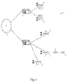
fig. 3 a particular radio coverage area of a mobile network comprising: - a femto cell C1, which is operated by a femto base station BS1, and
- a macro cell C2, which is operated by a macro base station BS2.
- The cells C1 and C2 may share the same frequency band, in which case soft or hard handovers are possible between the cells C1 and C2, or may be assigned non-overlapping frequency bands, in which case only hard handovers are allowed.
- A UE UEX establishes a communication session at position a, within the coverage area of the femto cell A.
- The UE UEX next moves towards position c while the communication session is on-going.
- At position b, the received pilot signal from macro cell C2 is stronger than the received pilot signal from femto cell C1. Provided that the difference between the two received signals' strength is beyond some configured handover margin and stays there for a minimum of a TTT period, an outbound handover is triggered for handing over the on-going session towards the macro cell C2.
- There is seen in
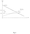
fig. 4 the chip-to-noise energy ratio Ec/No of a pilot signal broadcast within the femto cell C1 and the neighboring macro cell C2 as measured by the UE UEX while it leaves the femto cell C1. - Once the Ec/No value of the femto cell C1 falls below that of the macro cell C2 by at least a positive offset OFF1 value and for TTT1 seconds, the handover occurs. Over the time, the femto base station BS1 is capable of estimating an average Ec/No level at which handovers are typically performed. This is denoted by a handover reference threshold HOT.
- To have an accurate estimation of the handover threshold value HOT, the femto base station BS1 can calculate the moving average of HOT based on the handover observations over time:

wherein HOT(n) denotes the nth handover observation, and α is an averaging coefficient (0 < α < 1), where higher α values overwrites the older observations faster. - By introducing an anticipation handover threshold HOA as a potential handover threshold, the femto base station BS1 can be prepared to face a likely handover. The anticipation handover threshold HOA is defined as:

wherein OFF2 is a second positive anticipation offset. - The femto base station BS1 monitors the received Ec/No of the active UEs. Once the value falls below the anticipation threshold value HOA, the femto base station BS1 records the current transmit power of the UE as P_start, and starts commanding the UE to increase its transmit power level so that, by the time of the hand-over, the UE is already on an appropriate power level P_target to communicate to the remote macro base station BS2. Since the femto base station BS1 can estimate the typical or average value of Ec/No at which handovers are performed, the threshold value HOA can be simply calculated by adding an anticipation offset value OFF2 to this value. Additionally, the target power level P_target does not need to be accurate as the finer power control mechanism after the handover (or the power initialization procedure using open loop power control in case of hard handover) will adjust any power offset.
- There is plotted in
fig. 5 different uplink power control regimes as per the invention. - Once the UE's Ec/No is below the threshold value HOA, the femto base station BS1 starts to adapt the UE's transmit power appropriately.
- In its simplest form, this power adaptation can be a linear function of the receive Ec/No as measured by the UE that results in the uplink transmit power to be at P_target when the receive Ec/No equals HOT = HOA - OFF2, that is to say when the handover is expected to take place:

wherein P_UL denotes the uplink transmit power. This first option is plotted infig. 5 as a plain line. - While this provides a first order linear mapping of the UE's transmit power from P_start to P_target when Ec/No is decreasing from HOA to HOT = HOA - OFF2 respectively, it might be desirable to have higher order mapping. This is especially helpful as, in this case, the UE's transmit power remains lower when compared to the first order mapping. This would evidently reduce the total interference level and avoid over provisioning of all other UE's transmit power (note that all other UEs would respectively adapt their power to sustain their own SNIR values). To account for higher order mappings, equation (4) can be modified as:

wherein MO denotes the Mapping Order (MO). This second option is plotted as two dashed curves infig. 5 with MO set to 2 and 4 respectively. - It is to be noticed that the effective transmit power used by a UE in the ad-hoc power control regime is a staircase version of the plotted curves as the UE step-wise adjusts its transmit power upon receipt and interpretation of TPC commands from the base station(s), that is to say at specific time instances and at the specified power granularity.
- The solution works well with both hard and soft handovers. With hard handovers, the UE receives the power control commands only from the femto cell C1 and therefore the power is adapted in a desired way. With soft handovers however, the UE receives the power control commands both from the macro cell C1 and the femto cell C2 but will consider the more conservative power control commands (the one resulting in lower transmit power), which is very likely to be the femto cell commands.
- The solution can be optionally extended to include a timer that is activated immediately after the received Ec/No of the UE falls below HOA threshold. If no handover occurs after a pre-defined time period T_handover, the power control operation can be set back to its normal procedure. Further, the received Ec/No at the time of expiration of the timer is recorded as LHOA. This will avoid UE to over-provision the transmit power if the handover does no occur within a certain time period (e.g., the case when the femto cell user gets close to the femto cell coverage border and does not move from there any further).
- If the ad-hoc power control mechanism is cancelled when the received Ec/No of the UE is below HOA threshold due to expiration of the timer T_handover, it can be reactivated again if:

wherein RT is a reactivation threshold. - In other words, the algorithm is reactivated (after being canceled due to the timer expiration) if the received Ec/No of the UE drops further and falls bellow LHOA-RT.
- OFF2, T_handover and RT parameters are design parameters that can be fine-tuned by the manufacturer.
- It is to be noticed that the term 'comprising', also used in the claims, should not be interpreted as being restricted to the means listed thereafter. Thus, the scope of the expression 'a device comprising means A and B' should not be limited to devices consisting only of components A and B. It means that with respect to the present invention, the relevant components of the device are A and B.
- It is to be further noticed that the term 'coupled', also used in the claims, should not be interpreted as being restricted to direct connections only. Thus, the scope of the expression 'a device A coupled to a device B' should not be limited to devices or systems wherein an output of device A is directly connected to an input of device B, and/or vice-versa. It means that there exists a path between an output of A and an input of B, and/or vice-versa, which may be a path including other devices or means.
- The description and drawings merely illustrate the principles of the invention. It will thus be appreciated that those skilled in the art will be able to devise various arrangements that, although not explicitly described or shown herein, embody the principles of the invention. Furthermore, all examples recited herein are principally intended expressly to be only for pedagogical purposes to aid the reader in understanding the principles of the invention and the concepts contributed by the inventor(s) to furthering the art, and are to be construed as being without limitation to such specifically recited examples and conditions. Moreover, all statements herein reciting principles, aspects, and embodiments of the invention, as well as specific examples thereof, are intended to encompass equivalents thereof.
- The functions of the various elements shown in the figures may be provided through the use of dedicated hardware as well as hardware capable of executing software in association with appropriate software. When provided by a processor, the functions may be provided by a single dedicated processor, by a single shared processor, or by a plurality of individual processors, some of which may be shared. Moreover, a processor should not be construed to refer exclusively to hardware capable of executing software, and may implicitly include, without limitation, digital signal processor (DSP) hardware, network processor, application specific integrated circuit (ASIC), field programmable gate array (FPGA), etc. Other hardware, conventional and/or custom, such as read only memory (ROM), random access memory (RAM), and non volatile storage, may also be included.
Claims (12)
- A method for controlling the transmit power of a mobile station (UEX) served by a small cell (C1), wherein the method comprises the steps of detecting a measurement event anticipating the forthcoming fulfillment of a handover condition towards a neighboring macro cell (C2) by the mobile station, and thereupon step-wise increasing the transmit power level of the mobile station so as to reach a transmit power target (P_Target) when the handover condition is eventually fulfilled by the mobile station.
- A method according to claim 1, wherein the handover condition is a condition whereby the macro cell is measured as being offset better than the small cell by a first positive handover offset (OFF1), thereby yielding a reference receive signal strength or quality threshold (HOT) in the small cell for handover towards the macro cell, and the measurement event is a measurement event whereby a current receive strength or quality level (Ec/No) for the mobile station in the small cell was measured as being below a handover anticipation threshold (HOA) which is the sum of the reference receive signal strength or quality threshold and a second positive anticipation offset (OFF2).
- A method according to claim 1 or 2, wherein the transmit power target is for compensating for an estimated downlink path loss for the mobile station in the macro cell.
- A method according to claim 3, wherein the transmit power target is determined by measuring a receive signal strength of a reference pilot signal broadcast within the macro cell at a nominal downlink transmit power.
- A method according to any of claims 1 to 4, wherein the step-wise increase of the transmit power is a monotonically-decreasing function of a current receive strength or quality level (Ec/No) for the mobile station in the small cell.
- A method according to claim 5, wherein the step-wise increase of the transmit power corresponds to a linear power increase (MO=1) from an initial transmit power (P_Start) used by the mobile station in the small cell when the measurement event is detected up to the transmit power target.
- A method according to claim 5, wherein the step-wise increase of the transmit power corresponds to a second or higher order polynomial power increase (MO>1) from an initial transmit power (P_Start) used by the mobile station in the small cell when the measurement event is detected up to the transmit power target.
- A method according to any of claims 1 to 7, wherein the method further comprises the step of withdrawing the increase of the transmit power level for the mobile station if no handover towards the macro cell took place for the mobile station during a handover confirmation time period triggered upon detection of the measurement event.
- A transmit power controller (150) for controlling the transmit power of a mobile station (UEX) served by a small cell (C1), and configured to detect a measurement event anticipating the forthcoming fulfillment of a handover condition towards a neighboring macro cell (C2) by the mobile station, and thereupon to step-wise increase the transmit power level of the mobile station so as to reach a transmit power target (P_Target) when the handover condition is eventually fulfilled by the mobile station.
- A radio access point (100) comprising a transmit power controller (150) according to claim 9, and configured to operate the small cell.
- A radio access point (100) according to claim 10, wherein the radio access point is a femto base station.
- A radio access point (100) according to claim 10, wherein the radio access point is a pico, metro or micro base station.
Priority Applications (9)
| Application Number | Priority Date | Filing Date | Title |
|---|---|---|---|
| ES12305312.6T ES2635214T3 (en) | 2012-03-16 | 2012-03-16 | Proactive increase in uplink transmission power in small cells after outgoing transfers |
| PL12305312T PL2640127T3 (en) | 2012-03-16 | 2012-03-16 | Proactive uplink transmit power increase in small cells upon outbound handovers |
| EP12305312.6A EP2640127B1 (en) | 2012-03-16 | 2012-03-16 | Proactive uplink transmit power increase in small cells upon outbound handovers |
| TW102106567A TWI486077B (en) | 2012-03-16 | 2013-02-25 | Proactive uplink transmit power increase in small cells upon outbound handovers |
| KR1020147028891A KR101751219B1 (en) | 2012-03-16 | 2013-03-14 | Proactive uplink transmit power increase in small cells upon outbound handovers |
| CN201380014730.0A CN104170458B (en) | 2012-03-16 | 2013-03-14 | Active increase of uplink transmit power in small cells during outbound handover |
| US14/385,320 US9319995B2 (en) | 2012-03-16 | 2013-03-14 | Proactive uplink transmit power increase in small cells upon outbound handovers |
| JP2014561446A JP5993035B2 (en) | 2012-03-16 | 2013-03-14 | Uplink transmission power increase in anticipation of small cells during outbound handover |
| PCT/EP2013/055201 WO2013135797A1 (en) | 2012-03-16 | 2013-03-14 | Proactive uplink transmit power increase in small cells upon outbound handovers |
Applications Claiming Priority (1)
| Application Number | Priority Date | Filing Date | Title |
|---|---|---|---|
| EP12305312.6A EP2640127B1 (en) | 2012-03-16 | 2012-03-16 | Proactive uplink transmit power increase in small cells upon outbound handovers |
Publications (2)
| Publication Number | Publication Date |
|---|---|
| EP2640127A1 true EP2640127A1 (en) | 2013-09-18 |
| EP2640127B1 EP2640127B1 (en) | 2017-05-03 |
Family
ID=47878052
Family Applications (1)
| Application Number | Title | Priority Date | Filing Date |
|---|---|---|---|
| EP12305312.6A Not-in-force EP2640127B1 (en) | 2012-03-16 | 2012-03-16 | Proactive uplink transmit power increase in small cells upon outbound handovers |
Country Status (9)
| Country | Link |
|---|---|
| US (1) | US9319995B2 (en) |
| EP (1) | EP2640127B1 (en) |
| JP (1) | JP5993035B2 (en) |
| KR (1) | KR101751219B1 (en) |
| CN (1) | CN104170458B (en) |
| ES (1) | ES2635214T3 (en) |
| PL (1) | PL2640127T3 (en) |
| TW (1) | TWI486077B (en) |
| WO (1) | WO2013135797A1 (en) |
Families Citing this family (14)
| Publication number | Priority date | Publication date | Assignee | Title |
|---|---|---|---|---|
| US9042894B2 (en) * | 2013-03-07 | 2015-05-26 | Qualcomm Incorporated | Uplink interference mitigation by adapting open cell transmission power |
| US9578605B2 (en) | 2013-09-27 | 2017-02-21 | Parallel Wireless, Inc. | Adjusting transmit power across a network |
| KR20170018059A (en) | 2014-06-20 | 2017-02-15 | 후아웨이 테크놀러지 컴퍼니 리미티드 | Transmission power control command word generation method, device and system |
| US10772051B2 (en) | 2014-08-15 | 2020-09-08 | Parallel Wireless, Inc. | Inter-cell interference mitigation |
| CN107005950B (en) * | 2014-12-01 | 2020-10-27 | 瑞典爱立信有限公司 | Method and network node for managing transmission power of a wireless device |
| US10986691B2 (en) | 2016-03-18 | 2021-04-20 | Parallel Wireless, Inc. | Base station grouping for topology hiding |
| US11665597B2 (en) | 2016-03-18 | 2023-05-30 | Parallel Wireless, Inc. | UE mobility across super-cells |
| EP3430731B1 (en) | 2016-03-18 | 2021-02-17 | Parallel Wireless Inc. | Iugw architecture |
| US10638394B2 (en) * | 2016-09-07 | 2020-04-28 | Parallel Wireless, Inc. | Multi-stage handover |
| US10285097B2 (en) | 2017-02-16 | 2019-05-07 | Parallel Wireless, Inc. | Sinter and intrasearch beacon |
| CN111356193B (en) * | 2018-12-24 | 2022-11-18 | 海能达通信股份有限公司 | Terminal handover method and communication terminal |
| US12028915B1 (en) * | 2020-12-11 | 2024-07-02 | Sprint Spectrum Lp | Dual connectivity based on path loss and transmit power |
| US11588910B2 (en) * | 2022-03-14 | 2023-02-21 | Meta Platforms Technologies, Llc | Offloading visual frames to a gateway device |
| US11880950B2 (en) | 2022-03-14 | 2024-01-23 | Meta Platforms Technologies, Llc | Selective offload of workloads to edge devices |
Citations (2)
| Publication number | Priority date | Publication date | Assignee | Title |
|---|---|---|---|---|
| US20110039561A1 (en) * | 2009-08-17 | 2011-02-17 | Motorola, Inc. | Mitigation of Uplink Interference from Wireless Communication Device Connected to a Micro Cell |
| WO2011054374A1 (en) * | 2009-11-03 | 2011-05-12 | Nokia Siemens Networks Oy | Power control setting in a low power network node |
Family Cites Families (16)
| Publication number | Priority date | Publication date | Assignee | Title |
|---|---|---|---|---|
| JP3121541B2 (en) * | 1996-04-24 | 2001-01-09 | 株式会社エヌ・ティ・ティ・ドコモ | Synchronization establishment method, base station apparatus and mobile station apparatus in CDMA mobile communication system |
| US6381230B1 (en) * | 1998-07-28 | 2002-04-30 | Qualcomm Incorporated | Method and system for providing personal base station communications |
| GB0021544D0 (en) * | 2000-09-01 | 2000-10-18 | Nokia Networks Oy | Broadcasting in a communication system |
| US6615044B2 (en) * | 2001-06-06 | 2003-09-02 | Nokia Mobile Phones, Ltd. | Method of WCDMA coverage based handover triggering |
| JPWO2002104056A1 (en) | 2001-06-14 | 2004-10-07 | 三菱電機株式会社 | Communication traffic control method |
| CN101312598B (en) * | 2002-04-03 | 2013-07-24 | 日本电气株式会社 | Cellular system, base station, mobile station, and communication control method |
| US8369859B2 (en) * | 2006-05-22 | 2013-02-05 | Alcatel Lucent | Controlling transmit power of picocell base units |
| KR101469159B1 (en) * | 2008-05-21 | 2014-12-05 | 삼성전자주식회사 | Apparatus and method for removing interference in a wireless communication system |
| KR101520696B1 (en) | 2008-11-26 | 2015-05-15 | 엘지전자 주식회사 | Method of controlling power using dynamic step size |
| WO2010078476A1 (en) * | 2009-01-02 | 2010-07-08 | Motorola, Inc. | Power control in a multi-layer cellular communication system |
| US8817702B2 (en) | 2009-07-22 | 2014-08-26 | Qualcomm Incorporated | Mitigation of interference due to peer-to-peer communication |
| WO2011070643A1 (en) * | 2009-12-07 | 2011-06-16 | 富士通株式会社 | Mobile communication system, base station apparatus and handover executing method |
| WO2011099782A2 (en) * | 2010-02-11 | 2011-08-18 | 엘지전자 주식회사 | Device for controlling uplink transmission power and a method for the same |
| JP5340995B2 (en) * | 2010-02-26 | 2013-11-13 | 株式会社日立製作所 | Base station, radio communication system and interference-based handover control method |
| JP5352513B2 (en) | 2010-03-31 | 2013-11-27 | 株式会社日立製作所 | Wireless communication system and handover control method |
| JP5269831B2 (en) * | 2010-04-30 | 2013-08-21 | 株式会社エヌ・ティ・ティ・ドコモ | Base station apparatus, mobile terminal apparatus and communication control method |
-
2012
- 2012-03-16 PL PL12305312T patent/PL2640127T3/en unknown
- 2012-03-16 ES ES12305312.6T patent/ES2635214T3/en active Active
- 2012-03-16 EP EP12305312.6A patent/EP2640127B1/en not_active Not-in-force
-
2013
- 2013-02-25 TW TW102106567A patent/TWI486077B/en not_active IP Right Cessation
- 2013-03-14 WO PCT/EP2013/055201 patent/WO2013135797A1/en not_active Ceased
- 2013-03-14 JP JP2014561446A patent/JP5993035B2/en not_active Expired - Fee Related
- 2013-03-14 US US14/385,320 patent/US9319995B2/en not_active Expired - Fee Related
- 2013-03-14 CN CN201380014730.0A patent/CN104170458B/en not_active Expired - Fee Related
- 2013-03-14 KR KR1020147028891A patent/KR101751219B1/en not_active Expired - Fee Related
Patent Citations (2)
| Publication number | Priority date | Publication date | Assignee | Title |
|---|---|---|---|---|
| US20110039561A1 (en) * | 2009-08-17 | 2011-02-17 | Motorola, Inc. | Mitigation of Uplink Interference from Wireless Communication Device Connected to a Micro Cell |
| WO2011054374A1 (en) * | 2009-11-03 | 2011-05-12 | Nokia Siemens Networks Oy | Power control setting in a low power network node |
Non-Patent Citations (1)
| Title |
|---|
| 3GPP: "3rd Generation Partnership Project; Technical Specification Group Radio Access Network; Physical layer procedures (FDD) (Release 8)", 3GPP DRAFT; DRAFT25214-8D0, 3RD GENERATION PARTNERSHIP PROJECT (3GPP), MOBILE COMPETENCE CENTRE ; 650, ROUTE DES LUCIOLES ; F-06921 SOPHIA-ANTIPOLIS CEDEX ; FRANCE, 7 March 2012 (2012-03-07), XP050561755 * |
Also Published As
| Publication number | Publication date |
|---|---|
| EP2640127B1 (en) | 2017-05-03 |
| KR20150001755A (en) | 2015-01-06 |
| US20150065135A1 (en) | 2015-03-05 |
| ES2635214T3 (en) | 2017-10-02 |
| PL2640127T3 (en) | 2017-08-31 |
| JP5993035B2 (en) | 2016-09-14 |
| TWI486077B (en) | 2015-05-21 |
| US9319995B2 (en) | 2016-04-19 |
| TW201349907A (en) | 2013-12-01 |
| WO2013135797A1 (en) | 2013-09-19 |
| CN104170458A (en) | 2014-11-26 |
| KR101751219B1 (en) | 2017-07-11 |
| CN104170458B (en) | 2018-04-10 |
| JP2015515782A (en) | 2015-05-28 |
Similar Documents
| Publication | Publication Date | Title |
|---|---|---|
| US9319995B2 (en) | Proactive uplink transmit power increase in small cells upon outbound handovers | |
| JP2015515782A5 (en) | ||
| US9072020B2 (en) | Methods and apparatus to support coordinated interference mitigation in multi-tier networks | |
| US9629039B2 (en) | Cell partitioning for high-speed users | |
| EP2266337B1 (en) | Configuration of access points in a telecommunications network | |
| EP2592865B1 (en) | Call drop avoidance during radio link failure | |
| US8515353B2 (en) | Method and arrangement in a radio base station, in a radio communications network | |
| US8428602B2 (en) | Methods for enhancing performance of open-access and closed-access femtocells | |
| US8050629B2 (en) | Optimizing power settings in a communication system to mitigate interference | |
| US20110255514A1 (en) | Method and apparatus of communication | |
| US9167492B2 (en) | Cell handover and activation in heterogeneous networks | |
| KR20160100328A (en) | Small cell clusters for signaling load reduction, time synchronization, kpi filtering and spectrum coordination | |
| WO2013108315A1 (en) | Wireless communication system, transmission power control device, base station device, parameter supply device, and transmission power control method | |
| US10231188B1 (en) | Dynamic uplink transmit power control | |
| US20130225179A1 (en) | Femtocell base station, and a method of selecting carrier frequency band of a femtocell base station | |
| US9055540B2 (en) | Method for calculating a transmit power for a user equipment | |
| EP2613588A1 (en) | Improved handling of high-speed users within a heterogeneous mobile network by means of pico cell's Almost Blank Subframes | |
| US9008015B2 (en) | Apparatus and method for mobile assisted reverse link interference management | |
| EP2496028B1 (en) | A small cell base station, a vehicle for passengers and method of automatically setting the maximum permitted transmit power of a small cell base station | |
| Joshi et al. | Performance analysis of active handoff in CDMA2000 femtocells |
Legal Events
| Date | Code | Title | Description |
|---|---|---|---|
| PUAI | Public reference made under article 153(3) epc to a published international application that has entered the european phase |
Free format text: ORIGINAL CODE: 0009012 |
|
| AK | Designated contracting states |
Kind code of ref document: A1 Designated state(s): AL AT BE BG CH CY CZ DE DK EE ES FI FR GB GR HR HU IE IS IT LI LT LU LV MC MK MT NL NO PL PT RO RS SE SI SK SM TR |
|
| AX | Request for extension of the european patent |
Extension state: BA ME |
|
| 17P | Request for examination filed |
Effective date: 20140318 |
|
| RBV | Designated contracting states (corrected) |
Designated state(s): AL AT BE BG CH CY CZ DE DK EE ES FI FR GB GR HR HU IE IS IT LI LT LU LV MC MK MT NL NO PL PT RO RS SE SI SK SM TR |
|
| RAP1 | Party data changed (applicant data changed or rights of an application transferred) |
Owner name: ALCATEL LUCENT |
|
| GRAP | Despatch of communication of intention to grant a patent |
Free format text: ORIGINAL CODE: EPIDOSNIGR1 |
|
| RIC1 | Information provided on ipc code assigned before grant |
Ipc: H04W 36/00 20090101AFI20161024BHEP Ipc: H04W 52/12 20090101ALI20161024BHEP Ipc: H04W 52/14 20090101ALI20161024BHEP |
|
| INTG | Intention to grant announced |
Effective date: 20161122 |
|
| GRAJ | Information related to disapproval of communication of intention to grant by the applicant or resumption of examination proceedings by the epo deleted |
Free format text: ORIGINAL CODE: EPIDOSDIGR1 |
|
| GRAR | Information related to intention to grant a patent recorded |
Free format text: ORIGINAL CODE: EPIDOSNIGR71 |
|
| GRAS | Grant fee paid |
Free format text: ORIGINAL CODE: EPIDOSNIGR3 |
|
| INTC | Intention to grant announced (deleted) | ||
| INTG | Intention to grant announced |
Effective date: 20170207 |
|
| GRAA | (expected) grant |
Free format text: ORIGINAL CODE: 0009210 |
|
| AK | Designated contracting states |
Kind code of ref document: B1 Designated state(s): AL AT BE BG CH CY CZ DE DK EE ES FI FR GB GR HR HU IE IS IT LI LT LU LV MC MK MT NL NO PL PT RO RS SE SI SK SM TR |
|
| REG | Reference to a national code |
Ref country code: GB Ref legal event code: FG4D |
|
| REG | Reference to a national code |
Ref country code: AT Ref legal event code: REF Ref document number: 891236 Country of ref document: AT Kind code of ref document: T Effective date: 20170515 Ref country code: CH Ref legal event code: EP |
|
| REG | Reference to a national code |
Ref country code: IE Ref legal event code: FG4D |
|
| REG | Reference to a national code |
Ref country code: DE Ref legal event code: R096 Ref document number: 602012031865 Country of ref document: DE |
|
| REG | Reference to a national code |
Ref country code: NL Ref legal event code: MP Effective date: 20170503 |
|
| REG | Reference to a national code |
Ref country code: AT Ref legal event code: MK05 Ref document number: 891236 Country of ref document: AT Kind code of ref document: T Effective date: 20170503 |
|
| REG | Reference to a national code |
Ref country code: LT Ref legal event code: MG4D |
|
| REG | Reference to a national code |
Ref country code: ES Ref legal event code: FG2A Ref document number: 2635214 Country of ref document: ES Kind code of ref document: T3 Effective date: 20171002 |
|
| PG25 | Lapsed in a contracting state [announced via postgrant information from national office to epo] |
Ref country code: GR Free format text: LAPSE BECAUSE OF FAILURE TO SUBMIT A TRANSLATION OF THE DESCRIPTION OR TO PAY THE FEE WITHIN THE PRESCRIBED TIME-LIMIT Effective date: 20170804 Ref country code: NO Free format text: LAPSE BECAUSE OF FAILURE TO SUBMIT A TRANSLATION OF THE DESCRIPTION OR TO PAY THE FEE WITHIN THE PRESCRIBED TIME-LIMIT Effective date: 20170803 Ref country code: HR Free format text: LAPSE BECAUSE OF FAILURE TO SUBMIT A TRANSLATION OF THE DESCRIPTION OR TO PAY THE FEE WITHIN THE PRESCRIBED TIME-LIMIT Effective date: 20170503 Ref country code: AT Free format text: LAPSE BECAUSE OF FAILURE TO SUBMIT A TRANSLATION OF THE DESCRIPTION OR TO PAY THE FEE WITHIN THE PRESCRIBED TIME-LIMIT Effective date: 20170503 Ref country code: FI Free format text: LAPSE BECAUSE OF FAILURE TO SUBMIT A TRANSLATION OF THE DESCRIPTION OR TO PAY THE FEE WITHIN THE PRESCRIBED TIME-LIMIT Effective date: 20170503 Ref country code: LT Free format text: LAPSE BECAUSE OF FAILURE TO SUBMIT A TRANSLATION OF THE DESCRIPTION OR TO PAY THE FEE WITHIN THE PRESCRIBED TIME-LIMIT Effective date: 20170503 |
|
| PG25 | Lapsed in a contracting state [announced via postgrant information from national office to epo] |
Ref country code: LV Free format text: LAPSE BECAUSE OF FAILURE TO SUBMIT A TRANSLATION OF THE DESCRIPTION OR TO PAY THE FEE WITHIN THE PRESCRIBED TIME-LIMIT Effective date: 20170503 Ref country code: RS Free format text: LAPSE BECAUSE OF FAILURE TO SUBMIT A TRANSLATION OF THE DESCRIPTION OR TO PAY THE FEE WITHIN THE PRESCRIBED TIME-LIMIT Effective date: 20170503 Ref country code: SE Free format text: LAPSE BECAUSE OF FAILURE TO SUBMIT A TRANSLATION OF THE DESCRIPTION OR TO PAY THE FEE WITHIN THE PRESCRIBED TIME-LIMIT Effective date: 20170503 Ref country code: NL Free format text: LAPSE BECAUSE OF FAILURE TO SUBMIT A TRANSLATION OF THE DESCRIPTION OR TO PAY THE FEE WITHIN THE PRESCRIBED TIME-LIMIT Effective date: 20170503 Ref country code: BG Free format text: LAPSE BECAUSE OF FAILURE TO SUBMIT A TRANSLATION OF THE DESCRIPTION OR TO PAY THE FEE WITHIN THE PRESCRIBED TIME-LIMIT Effective date: 20170803 Ref country code: IS Free format text: LAPSE BECAUSE OF FAILURE TO SUBMIT A TRANSLATION OF THE DESCRIPTION OR TO PAY THE FEE WITHIN THE PRESCRIBED TIME-LIMIT Effective date: 20170903 |
|
| PG25 | Lapsed in a contracting state [announced via postgrant information from national office to epo] |
Ref country code: RO Free format text: LAPSE BECAUSE OF FAILURE TO SUBMIT A TRANSLATION OF THE DESCRIPTION OR TO PAY THE FEE WITHIN THE PRESCRIBED TIME-LIMIT Effective date: 20170503 Ref country code: DK Free format text: LAPSE BECAUSE OF FAILURE TO SUBMIT A TRANSLATION OF THE DESCRIPTION OR TO PAY THE FEE WITHIN THE PRESCRIBED TIME-LIMIT Effective date: 20170503 Ref country code: SK Free format text: LAPSE BECAUSE OF FAILURE TO SUBMIT A TRANSLATION OF THE DESCRIPTION OR TO PAY THE FEE WITHIN THE PRESCRIBED TIME-LIMIT Effective date: 20170503 Ref country code: EE Free format text: LAPSE BECAUSE OF FAILURE TO SUBMIT A TRANSLATION OF THE DESCRIPTION OR TO PAY THE FEE WITHIN THE PRESCRIBED TIME-LIMIT Effective date: 20170503 Ref country code: CZ Free format text: LAPSE BECAUSE OF FAILURE TO SUBMIT A TRANSLATION OF THE DESCRIPTION OR TO PAY THE FEE WITHIN THE PRESCRIBED TIME-LIMIT Effective date: 20170503 |
|
| REG | Reference to a national code |
Ref country code: DE Ref legal event code: R097 Ref document number: 602012031865 Country of ref document: DE |
|
| PG25 | Lapsed in a contracting state [announced via postgrant information from national office to epo] |
Ref country code: SM Free format text: LAPSE BECAUSE OF FAILURE TO SUBMIT A TRANSLATION OF THE DESCRIPTION OR TO PAY THE FEE WITHIN THE PRESCRIBED TIME-LIMIT Effective date: 20170503 |
|
| PLBE | No opposition filed within time limit |
Free format text: ORIGINAL CODE: 0009261 |
|
| STAA | Information on the status of an ep patent application or granted ep patent |
Free format text: STATUS: NO OPPOSITION FILED WITHIN TIME LIMIT |
|
| REG | Reference to a national code |
Ref country code: FR Ref legal event code: PLFP Year of fee payment: 7 |
|
| REG | Reference to a national code |
Ref country code: CH Ref legal event code: PCOW Free format text: NEW ADDRESS: SITE NOKIA PARIS SACLAY ROUTE DE VILLEJUST, 91620 NOZAY (FR) |
|
| 26N | No opposition filed |
Effective date: 20180206 |
|
| PG25 | Lapsed in a contracting state [announced via postgrant information from national office to epo] |
Ref country code: SI Free format text: LAPSE BECAUSE OF FAILURE TO SUBMIT A TRANSLATION OF THE DESCRIPTION OR TO PAY THE FEE WITHIN THE PRESCRIBED TIME-LIMIT Effective date: 20170503 |
|
| REG | Reference to a national code |
Ref country code: CH Ref legal event code: PL |
|
| PG25 | Lapsed in a contracting state [announced via postgrant information from national office to epo] |
Ref country code: MC Free format text: LAPSE BECAUSE OF FAILURE TO SUBMIT A TRANSLATION OF THE DESCRIPTION OR TO PAY THE FEE WITHIN THE PRESCRIBED TIME-LIMIT Effective date: 20170503 |
|
| REG | Reference to a national code |
Ref country code: BE Ref legal event code: MM Effective date: 20180331 |
|
| REG | Reference to a national code |
Ref country code: IE Ref legal event code: MM4A |
|
| PG25 | Lapsed in a contracting state [announced via postgrant information from national office to epo] |
Ref country code: LU Free format text: LAPSE BECAUSE OF NON-PAYMENT OF DUE FEES Effective date: 20180316 |
|
| PG25 | Lapsed in a contracting state [announced via postgrant information from national office to epo] |
Ref country code: IE Free format text: LAPSE BECAUSE OF NON-PAYMENT OF DUE FEES Effective date: 20180316 |
|
| PG25 | Lapsed in a contracting state [announced via postgrant information from national office to epo] |
Ref country code: BE Free format text: LAPSE BECAUSE OF NON-PAYMENT OF DUE FEES Effective date: 20180331 Ref country code: LI Free format text: LAPSE BECAUSE OF NON-PAYMENT OF DUE FEES Effective date: 20180331 Ref country code: CH Free format text: LAPSE BECAUSE OF NON-PAYMENT OF DUE FEES Effective date: 20180331 |
|
| PG25 | Lapsed in a contracting state [announced via postgrant information from national office to epo] |
Ref country code: MT Free format text: LAPSE BECAUSE OF NON-PAYMENT OF DUE FEES Effective date: 20180316 |
|
| PG25 | Lapsed in a contracting state [announced via postgrant information from national office to epo] |
Ref country code: TR Free format text: LAPSE BECAUSE OF FAILURE TO SUBMIT A TRANSLATION OF THE DESCRIPTION OR TO PAY THE FEE WITHIN THE PRESCRIBED TIME-LIMIT Effective date: 20170503 |
|
| PG25 | Lapsed in a contracting state [announced via postgrant information from national office to epo] |
Ref country code: HU Free format text: LAPSE BECAUSE OF FAILURE TO SUBMIT A TRANSLATION OF THE DESCRIPTION OR TO PAY THE FEE WITHIN THE PRESCRIBED TIME-LIMIT; INVALID AB INITIO Effective date: 20120316 Ref country code: PT Free format text: LAPSE BECAUSE OF FAILURE TO SUBMIT A TRANSLATION OF THE DESCRIPTION OR TO PAY THE FEE WITHIN THE PRESCRIBED TIME-LIMIT Effective date: 20170503 |
|
| PG25 | Lapsed in a contracting state [announced via postgrant information from national office to epo] |
Ref country code: CY Free format text: LAPSE BECAUSE OF FAILURE TO SUBMIT A TRANSLATION OF THE DESCRIPTION OR TO PAY THE FEE WITHIN THE PRESCRIBED TIME-LIMIT Effective date: 20170503 Ref country code: MK Free format text: LAPSE BECAUSE OF NON-PAYMENT OF DUE FEES Effective date: 20170503 |
|
| PG25 | Lapsed in a contracting state [announced via postgrant information from national office to epo] |
Ref country code: AL Free format text: LAPSE BECAUSE OF FAILURE TO SUBMIT A TRANSLATION OF THE DESCRIPTION OR TO PAY THE FEE WITHIN THE PRESCRIBED TIME-LIMIT Effective date: 20170503 |
|
| PGFP | Annual fee paid to national office [announced via postgrant information from national office to epo] |
Ref country code: PL Payment date: 20220210 Year of fee payment: 11 Ref country code: IT Payment date: 20220210 Year of fee payment: 11 Ref country code: FR Payment date: 20220209 Year of fee payment: 11 |
|
| PGFP | Annual fee paid to national office [announced via postgrant information from national office to epo] |
Ref country code: ES Payment date: 20220405 Year of fee payment: 11 |
|
| PGFP | Annual fee paid to national office [announced via postgrant information from national office to epo] |
Ref country code: GB Payment date: 20230202 Year of fee payment: 12 Ref country code: DE Payment date: 20230131 Year of fee payment: 12 |
|
| PG25 | Lapsed in a contracting state [announced via postgrant information from national office to epo] |
Ref country code: FR Free format text: LAPSE BECAUSE OF NON-PAYMENT OF DUE FEES Effective date: 20230331 |
|
| PG25 | Lapsed in a contracting state [announced via postgrant information from national office to epo] |
Ref country code: IT Free format text: LAPSE BECAUSE OF NON-PAYMENT OF DUE FEES Effective date: 20230316 |
|
| REG | Reference to a national code |
Ref country code: ES Ref legal event code: FD2A Effective date: 20240507 |
|
| PG25 | Lapsed in a contracting state [announced via postgrant information from national office to epo] |
Ref country code: ES Free format text: LAPSE BECAUSE OF NON-PAYMENT OF DUE FEES Effective date: 20230317 |
|
| PG25 | Lapsed in a contracting state [announced via postgrant information from national office to epo] |
Ref country code: ES Free format text: LAPSE BECAUSE OF NON-PAYMENT OF DUE FEES Effective date: 20230317 |
|
| PG25 | Lapsed in a contracting state [announced via postgrant information from national office to epo] |
Ref country code: PL Free format text: LAPSE BECAUSE OF NON-PAYMENT OF DUE FEES Effective date: 20230316 |
|
| PG25 | Lapsed in a contracting state [announced via postgrant information from national office to epo] |
Ref country code: PL Free format text: LAPSE BECAUSE OF NON-PAYMENT OF DUE FEES Effective date: 20230316 |
|
| REG | Reference to a national code |
Ref country code: DE Ref legal event code: R119 Ref document number: 602012031865 Country of ref document: DE |
|
| GBPC | Gb: european patent ceased through non-payment of renewal fee |
Effective date: 20240316 |
|
| PG25 | Lapsed in a contracting state [announced via postgrant information from national office to epo] |
Ref country code: DE Free format text: LAPSE BECAUSE OF NON-PAYMENT OF DUE FEES Effective date: 20241001 |
|
| PG25 | Lapsed in a contracting state [announced via postgrant information from national office to epo] |
Ref country code: GB Free format text: LAPSE BECAUSE OF NON-PAYMENT OF DUE FEES Effective date: 20240316 |
|
| PG25 | Lapsed in a contracting state [announced via postgrant information from national office to epo] |
Ref country code: GB Free format text: LAPSE BECAUSE OF NON-PAYMENT OF DUE FEES Effective date: 20240316 Ref country code: DE Free format text: LAPSE BECAUSE OF NON-PAYMENT OF DUE FEES Effective date: 20241001 |