EP2639976A1 - Inverse channel apparatus and transmitter, receiver and system containing the apparatus - Google Patents
Inverse channel apparatus and transmitter, receiver and system containing the apparatus Download PDFInfo
- Publication number
- EP2639976A1 EP2639976A1 EP13158130.8A EP13158130A EP2639976A1 EP 2639976 A1 EP2639976 A1 EP 2639976A1 EP 13158130 A EP13158130 A EP 13158130A EP 2639976 A1 EP2639976 A1 EP 2639976A1
- Authority
- EP
- European Patent Office
- Prior art keywords
- nonlinear
- inverse
- channel
- ixpm
- damage
- Prior art date
- Legal status (The legal status is an assumption and is not a legal conclusion. Google has not performed a legal analysis and makes no representation as to the accuracy of the status listed.)
- Granted
Links
Images


Classifications
-
- H—ELECTRICITY
- H04—ELECTRIC COMMUNICATION TECHNIQUE
- H04B—TRANSMISSION
- H04B10/00—Transmission systems employing electromagnetic waves other than radio-waves, e.g. infrared, visible or ultraviolet light, or employing corpuscular radiation, e.g. quantum communication
- H04B10/25—Arrangements specific to fibre transmission
- H04B10/2507—Arrangements specific to fibre transmission for the reduction or elimination of distortion or dispersion
-
- H—ELECTRICITY
- H04—ELECTRIC COMMUNICATION TECHNIQUE
- H04B—TRANSMISSION
- H04B10/00—Transmission systems employing electromagnetic waves other than radio-waves, e.g. infrared, visible or ultraviolet light, or employing corpuscular radiation, e.g. quantum communication
- H04B10/25—Arrangements specific to fibre transmission
- H04B10/2507—Arrangements specific to fibre transmission for the reduction or elimination of distortion or dispersion
- H04B10/2543—Arrangements specific to fibre transmission for the reduction or elimination of distortion or dispersion due to fibre non-linearities, e.g. Kerr effect
Definitions
- the present invention relates to optical communication, and in particular to an inverse channel apparatus and transmitter, receiver and system containing the apparatus, for nonlinear compensation in an optical communication system.
- Phase noise and waveform damage caused by intra-channel nonlinearity are one of the sources leading to cost of a long-haul transmission optical communication system.
- digital pre-distortion (DPD) of a transmitter (document of L. Dou et al, OFC2011, paper OThF5) or digital Back-propagation (DBP) of a receiver (document of W. Yan et al., ECOC2011, paper Tu.3.A.2 ) may be used to compensate for the intra-channel nonlinearity damage.
- the inventors found that the ideas of these methods are focused on the calculation of nonlinearity damage of the whole or part of the channel, and the nonlinearity damage is eliminated by an operation of subtraction or phase modulation. Hence, there exists a problem of low performance due to incorrect calculation.
- the object of the embodiments of the present invention is to provide an inverse channel apparatus and transmitter, receiver and system containing the apparatus, by which a transmitted signal is recovered by being passed through an inverse channel after or before being transmitted in a practical channel, so as to eliminate damage in the channel.
- an inverse channel apparatus comprising:
- a receiver comprising one or a plurality of the inverse channel apparatuses, wherein when the receiver comprises one inverse channel apparatus, the inverse channel apparatus is provided between an analog-to-digital converter and an adaptive equalization and polarization demultiplexer of the receiver, the inverse channel apparatus being configured to build an inverse channel of an original channel; and when the receiver comprises a plurality of inverse channel apparatuses, the inverse channel apparatuses are provided between the analog-to-digital converter and the adaptive equalization and polarization demultiplexer of the receiver, each of the inverse channel apparatuses being configured to build inverse channels of a part of original channels.
- a transmitter comprising one or a plurality of the above-described inverse channel apparatuses, wherein when the transmitter comprises one inverse channel apparatus, the inverse channel apparatus is provided before an digital-to-analog converter of the transmitter, the inverse channel apparatus being configured to build an inverse channel of an original channel; and when the transmitter comprises a plurality of inverse channel apparatuses, the inverse channel apparatuses are provided before the digital-to-analog converter of the transmitter, each of the inverse channel apparatuses being configured to build inverse channels of a part of original channels.
- a transmission system comprising a transmitter and a receiver, the transmitter or receiver comprising one or a plurality of the inverse channel apparatuses.
- an input signal contains two polarization states as an example.
- the embodiments of the present invention are not limited thereto.
- linear damage and nonlinear damage may also be performed by the inverse channel apparatus of the embodiments of the present invention.
- FIG. 1 is a schematic diagram of the composition of the inverse channel apparatus.
- the inverse channel apparatus comprises: an inverse nonlinear calculating unit 101 and an inverse linear calculating unit 102, wherein the inverse nonlinear calculating unit 101 is configured to perform nonlinear additive calculation and nonlinear multiplicative calculation on input signals, so as to obtain signals containing nonlinear damage of the input signals on at least one polarization state; and the inverse linear calculating unit 102 is configured to calculate signals containing nonlinear damage and linear damage of the input signals on at least one polarization state according to the signals containing nonlinear damage of the input signals on at least one polarization state and a linear function of a channel.
- the input signals may comprise signals of two polarization states, and may also comprise signals of only one polarization state.
- signals containing nonlinear damage of the input signals on the two polarization states may be obtained by the inverse nonlinear calculating unit 101.
- H NL and V NL may be obtained by using the inverse nonlinear calculating unit 101; where H NL is a signal containing nonlinear damage of the signal H on the horizontal polarization state, and V NL is a signal containing nonlinear damage of the signal V on the vertical polarization state.
- signals containing nonlinear damage of the input signals on the polarization state may be obtained by using the inverse nonlinear calculating unit 101.
- the input signals only comprise a signal H of horizontal polarization state corresponding to that signal V of the input signals on vertical polarization state is 0, H NL is a signal containing nonlinear damage of the signal H on the horizontal polarization state may be obtained by using the inverse nonlinear calculating unit 101.
- the inverse nonlinear calculating unit 101 of this embodiment may be implemented by the composition as shown in Fig. 2A .
- the inverse nonlinear calculating unit 101 comprises: an inverse nonlinear coefficient calculating module 201, an inverse nonlinear perturbation calculating module 202 and an inverse nonlinear adding and multiplying module 203; wherein, the inverse nonlinear coefficient calculating module 201 is configured to calculate nonlinear coefficients of the inverse channel according to the channel configuration parameters; the inverse nonlinear perturbation calculating module 202 is configured to calculate nonlinear perturbation within the inverse channel according to the nonlinear coefficients of the inverse channel and the input signals; and the inverse nonlinear adding and multiplying module 203 is configured to calculate signals containing nonlinear damage of the input signals on at least one polarization state according to the nonlinear perturbation within the inverse channel and the input signals.
- the inverse nonlinear coefficient calculating module 201 may calculate nonlinear coefficients of the inverse channel in an existing method of calculating nonlinear coefficient.
- the existing method of calculating nonlinear coefficient is used to calculate nonlinear coefficients of an original channel, and nonlinear coefficients of an inverse channel are calculated in this embodiment
- the symbols of the channel configuration parameters of the original channel need to be inverted, that is, nonlinear coefficients of an inverse channel are calculated by using an existing method of calculating nonlinear coefficient and taking the inverted values of the symbols of the channel configuration parameters of the original channel as the channel configuration parameters of the inverse channel.
- the channel configuration parameters comprise mainly optical fiber parameters
- the optical fiber parameters may be any combination of an attenuation factor ( ⁇ ), a dispersion factor ( ⁇ ) and a nonlinear factor (y).
- ⁇ attenuation factor
- ⁇ dispersion factor
- y nonlinear factor
- the selection of a particular combination depends on the method of calculating nonlinear coefficient. For example, if the three optical fiber parameters are used in the method of calculating nonlinear coefficient, the symbols of the three optical fiber parameters are inverted first, and then the nonlinear coefficients of the inverse channel are calculated by using the method of calculating nonlinear coefficient.
- the inverse nonlinear perturbation calculating module 202 may be used to calculate the nonlinear perturbation within the inverse channel caused by intra-channel four-wave mixing (IFWM), intra-channel cross phase modulation (IXPM) and self-phase modulation (SPM).
- IFWM intra-channel four-wave mixing
- IXPM intra-channel cross phase modulation
- SPM self-phase modulation
- c is a nonlinear coefficient of the inverse channel
- m and n are relative moments
- l is an absolute moment
- H is an input signal on the horizontal polarization state
- V is an input signal on the vertical polarization state.
- the above formulae may also be referred to as additive-multiplicative models. These formulae are illustrative only, and any other calculation method and formulae eliminating nonlinear damage by performing additive and multiplicative calculation on input signals and nonlinear perturbation are all covered by the protection scope of the inverse nonlinear adding and multiplying module 203 of the embodiment of the present invention.
- the composition of the inverse nonlinear calculating unit 101 of this embodiment may be implemented as shown in Fig. 2B .
- the inverse nonlinear calculating unit 101 further comprises an optical fiber parameter estimating module 204.
- the optical fiber parameter estimating module 204 estimates parameters (including an attenuation factor ⁇ and/or a dispersion factor ⁇ and/or a nonlinear factor ⁇ ) of an optical fiber channel by analyzing input signals, such as H and V, so as to provide to the nonlinear coefficient calculating module.
- the method for estimating optical fiber parameters can also be implemented by known technology, such as the methods described in the documents of L. Liu et al., OFC2009, paper JWA36 and J. C. Geyer et al., PTL, vol. 20, pp. 776-778, 2008 , etc.
- the inverse linear calculating unit 102 may be implemented by an inverse dispersion module 301 shown in Fig. 3A .
- the inverse dispersion module 301 calculates signals containing nonlinear damage and linear damage of the input signals on at least one polarization state according to the signals containing nonlinear damage of the input signals on at least one polarization state and a dispersion transfer function of the channel.
- the inverse linear calculating unit 102 may be implemented by the composition as shown in Fig. 3B .
- the inverse linear calculating unit 102 further comprises an inverse polarization mode dispersion (PMD) module 302.
- PMD inverse polarization mode dispersion
- H IC V IC H PMD - 1 ⁇ H CD V CD ; where, H PMD is a PMD transmission matrix of the original channel, and H PMD - 1 is inversion of the PMD transmission matrix of the original channel.
- the inverse channel apparatus is applicable to but not limited to such modulation formats as mPSK, mQAM and mAPSK, and subcarrier multiplexing or OFDM technology.
- Fig. 4 is a schematic diagram of the composition of an inverse channel apparatus of a preferred embodiment of the present invention.
- the inverse channel apparatus comprises: an inverse nonlinear coefficient calculating module 401, an inverse nonlinear perturbation calculating module 402, an inverse nonlinear adding and multiplying module 403 and an inverse dispersion module 404.
- the inverse nonlinear coefficient calculating module 401 may be implemented by the above-described inverse nonlinear coefficient calculating module 201
- the inverse nonlinear perturbation calculating module 402 may be implemented by the above-described inverse nonlinear perturbation calculating module 202
- the inverse nonlinear adding and multiplying module 403 may be implemented by the above-described inverse nonlinear adding and multiplying module 203
- the inverse dispersion module 404 may be implemented by the above-described inverse dispersion module 301.
- the inverse nonlinear coefficient calculating module 201 As the inverse nonlinear coefficient calculating module 201, the inverse nonlinear perturbation calculating module 202, the inverse nonlinear adding and multiplying module 203 and the inverse dispersion module 301 have been described above, they shall not be described any further.
- a transmitted signal is recovered in a receiver by being passed through the inverse channel apparatus of the embodiment of the present invention after or before being transmitted in a practical channel, and intra-channel damages (including linear and nonlinear damages) are eliminated, thereby effectively compensating for intra-channel nonlinear damage of an optical fiber communication system.
- An embodiment of the present invention further provides a receiver, comprising the inverse channel apparatus of the Embodiment 1 of the present invention, in addition to original composition and functions.
- the receiver comprises one inverse channel apparatus of the Embodiment 1 of the present invention, and the inverse channel apparatus is provided between an analog-to-digital converter and an adaptive equalization and polarization demultiplexer of the receiver.
- the inverse channel apparatus is configured to build an inverse channel of whole of an original channel; that is, the inverse channel apparatus is configured to calculate each value by using parameters corresponding to the whole original channel.
- Fig. 5 is a schematic diagram of the composition of the receiver. Referring to Fig. 5 , the receiver comprises:
- the polarization diversity integrated front end 501, the analog-to-digital converter 502, the adaptive equalization and polarization demultiplexing device 504, the deviation compensating device 505, the carrier phase recovering device 506 and the data recovering device 507 may be implemented in an existing scheme, and the contents of which are incorporated herein, and shall not be described any further.
- the inverse channel apparatus 503 may be implemented by the inverse channel apparatus 1 of Embodiment 1, and the description of it is omitted herein.
- the receiver comprises a plurality of inverse channel apparatuses provided by the Embodiment 1 of the present invention, and the inverse channel apparatuses are also provided between the analog-to-digital converter and the adaptive equalization and polarization demultiplexer of the receiver.
- each of the inverse channel apparatuses (503 1 -503 N ) is configured to build an inverse channel of a part of an original channel; that is, each of the inverse channel apparatuses is configured to calculate each value by using parameters corresponding to part of the original channel.
- Fig. 6 is disassembled into N cascaded units; that is, an inverse channel of only a part of the original channel is constructed each time, and then the inverse channel of the whole original channel is constructed in a cascaded scheme, as shown in Fig. 6 .
- the nonlinear effect contained in each unit of the inverse channel is weakened, thereby improving the accuracy of the perturbation analysis.
- An extreme example is to take each span of an optical fiber as a cascade for constructing an inverse channel, without using an additive-multiplicative model and taking phase noise of the SPM into consideration only, and the structure of Fig. 6 is degraded into a known BP technology (document of E. Ip et al., JLT, vol. 26, pp.3416-3425, 2008 ).
- the receiver of the embodiment of the present invention uses the inverse channel apparatus, in which a transmitted signal is recovered in the receiver by being passed through the inverse channel apparatus after being transmitted in a practical channel, and intra-channel damages (including linear and nonlinear damages) are eliminated, thereby effectively compensating for intra-channel nonlinear damage of an optical fiber communication system.
- An embodiment of the present invention further provides a transmitter, comprising the inverse channel apparatus of the Embodiment 1 of the present invention, in addition to original composition and functions.
- the transmitter comprises one inverse channel apparatus of the Embodiment 1 of the present invention, and the inverse channel apparatus is provided before an digital-to-analog converter of the transmitter.
- the inverse channel apparatus is configured to build an inverse channel of whole of an original channel; that is, the inverse channel apparatus is configured to calculate each value by using parameters corresponding to the whole original channel.
- Fig. 7 is a schematic diagram of the composition of the transmitter.
- the transmitter comprises:
- the mode generating device 701, the digital-to-analog converter 703 and the modulator 704 may be implemented in an existing scheme, and the contents of which are incorporated herein, and shall not be described any further.
- the inverse channel apparatus 702 may be implemented by the inverse channel apparatus 1 of Embodiment 1, and the description of it is omitted herein.
- the transmitter comprises a plurality of inverse channel apparatuses provided by the Embodiment 1 of the present invention, and the inverse channel apparatuses are also provided before the digital-to-analog converter of the transmitter.
- each of the inverse channel apparatuses (702 1 -702 N ) is configured to build an inverse channel of a part of an original channel; that is, each of the inverse channel apparatuses is configured to calculate each value by using parameters corresponding to part of the original channel.
- Fig. 7 is disassembled into N cascaded units; that is, an inverse channel of only a part of the original channel is constructed each time, and then the inverse channel of the whole original channel is constructed in a cascaded scheme, as shown in Fig. 8 .
- the nonlinear effect contained in each unit of the inverse channel is weakened, thereby improving the accuracy of the perturbation analysis.
- An extreme example is to take each span of an optical fiber as a cascade for constructing an inverse channel, without using an additive-multiplicative model and taking phase noise of the SPM into consideration only, and the structure of Fig. 8 is degraded into a known BP technology (document of E. Ip et al., JLT, vol. 26, pp.3416-3425, 2008 ).
- the transmitter of the embodiment of the present invention uses the inverse channel apparatus, in which a transmitted signal is recovered in the receiver by being passed through the inverse channel apparatus after being transmitted in a practical channel, and intra-channel damages (including linear and nonlinear damages) are eliminated, thereby effectively compensating for intra-channel nonlinear damage of an optical fiber communication system.
- FIG. 9 is a schematic diagram of the composition of the transmission system.
- the transmission system comprises a transmitter 901 and a receiver 902, wherein the transmitter 901 or the receiver 902 comprises one or more inverse channel apparatuses of Embodiment 1.
- the transmitter 901 comprises one or a plurality of inverse channel apparatuses of Embodiment 1.
- the inverse channel apparatus builds an inverse channel of a whole original channel.
- each of the inverse channel apparatuses builds an inverse channel of a part of the whole original channel, and all the inverse channel apparatuses build an inverse channel of the whole original channel.
- the receiver 902 comprises one or a plurality of inverse channel apparatuses of Embodiment 1.
- the inverse channel apparatus builds an inverse channel of a whole original channel.
- each of the inverse channel apparatuses builds an inverse channel of a part of the whole original channel, and all the inverse channel apparatuses build an inverse channel of the whole original channel.
- both the transmitter 901 and the receiver 902 comprise one or a plurality of inverse channel apparatuses of Embodiment 1.
- Each of the inverse channel apparatuses builds an inverse channel of a part of the whole original channel, and all the inverse channel apparatuses build an inverse channel of the whole original channel.
- the transmitter and the receiver respectively builds an inverse channel of a half of an optical fiber transmission channel by one or a plurality of inverse channel apparatuses of Embodiment 1, which can also achieve an effect of compensating for a whole optical fiber transmission channel.
- the transmission system may be an optical fiber communication transmission system, and may also be other transmission systems needing nonlinear compensation, and this embodiment is not limited thereto.
- the transmission system of the embodiment of the present invention uses the inverse channel apparatus, in which a transmitted signal is recovered in the receiver by being passed through the inverse channel apparatus before and/or after being transmitted in a practical channel, and intra-channel damages (including linear and nonlinear damages) are eliminated, thereby effectively compensating for intra-channel nonlinear damage of an optical fiber communication system.
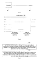
- Fig. 10 is a schematic diagram of comparison of performances of not using an inverse channel apparatus and using the inverse channel apparatus of the embodiment of the present invention in a typical long-haul coherent optical transmission experiment. It can be seen from Fig. 10 that the inverse channel apparatus of the embodiment of the present invention can effectively improve the performances of nonlinear compensation.
- FIG. 11 is a flowchart of the method. Referring to Fig. 11 , the method comprises:
- an inverse channel may be built by perturbation analysis of nonlinear effect, the nonlinear effect in the inverse channel may be indicated by a additive-multiplicative model (AM model), and then intra-channel nonlinear damage is calculated by using a perturbation method according to nonlinear coefficients.
- AM model additive-multiplicative model
- Mecozzi's method (document of A. Meccozi et al., PTL, vol. 12, pp. 392-394, 2000 ) or Wei's method (document of X. Wei, Opt. Lett., vol. 31, pp. 2544-2546, 2006 ) may be used for the calculation of the nonlinear coefficients.
- a typical example of the AM model is as described in document "A calculation apparatus for intra-channel nonlinearly introduced noise", the inventor of which is Liang Dou, with the application No. 201110287852.X .
- the nonlinear coefficients of the inverse channel may be calculated first according to the channel configuration parameters of the inverse channel, then the nonlinear perturbation within the inverse channel is calculated according to the nonlinear coefficients of the inverse channel and the input signals, and finally signals containing nonlinear damage of the input signals on at least one polarization state are calculated according the nonlinear perturbation within the inverse channel and the input signals.
- the channel configuration parameters of the inverse channel comprise optical fiber parameters, the optical fiber parameters comprising an attenuation factor ⁇ and/or a dispersion factor ⁇ and/or a nonlinear factor ⁇ ; wherein the nonlinear coefficients of the inverse channel may be calculated according to inverted values of the optical fiber parameters.
- the method of the embodiment of the present invention may be applicable to compensation for nonlinear damage of a whole optical fiber transmission channel (original channel), and also to compensation for nonlinear damage of part of an optical fiber transmission channel (original channel).
- this embodiment is not limited thereto.
- a particular difference mainly exists in the used channel configuration parameters, such as a length of an optical fiber in optical fiber parameters, etc.
- a transmitted signal is recovered in a receiver by being passed through the inverse channel after or before being transmitted in a practical channel, and intra-channel damages, including linear and nonlinear damages, are eliminated.
- each of the parts of the present invention may be implemented by hardware, software, firmware, or a combination thereof.
- multiple steps or methods may be realized by software or firmware that is stored in the memory and executed by an appropriate instruction executing system.
- a discrete logic circuit having a logic gate circuit for realizing logic functions of data signals
- application-specific integrated circuit having an appropriate combined logic gate circuit
- PGA programmable gate array
- FPGA field programmable gate array
- a computer readable medium can be any device that can contain, store, communicate with, propagate or transmit programs for use by an instruction executing system, device or apparatus, or can be used with the instruction executing system, device or apparatus.
- a computer readable medium may be, for example, but not limited to, a magnetic, optical, electromagnetic, infrared or semiconductor system, device, apparatus, or a propagation medium. More particular examples (inexhaustive lists) of a computer readable medium may comprise the following: an electrical connecting portion (electronic device) having one or more wirings, a portable computer hardware box (magnetic device), a random access memory (RAM) (electronic device), a read-only memory (ROM) (electronic device), an erasable programmable read-only memory (EPROM or flash memory) (electronic device), an optical fiber (optical device), and a portable compact disk read-only memory (CDROM) (optical device).
- an electrical connecting portion having one or more wirings
- a portable computer hardware box magnetic device
- RAM random access memory
- ROM read-only memory
- EPROM or flash memory erasable programmable read-only memory
- CDROM portable compact disk read-only memory
- a computer readable medium may be paper or other appropriate media on which the programs may be printed, as the programs may be obtained electronically through scanning optically the paper or other appropriate media and then compiling, interpreting, or processing in other appropriate manners, as necessary, and then the programs are stored in the computer memory.
Landscapes
- Physics & Mathematics (AREA)
- Electromagnetism (AREA)
- Engineering & Computer Science (AREA)
- Computer Networks & Wireless Communication (AREA)
- Signal Processing (AREA)
- Nonlinear Science (AREA)
- Optical Communication System (AREA)
Abstract
Description
- The present invention relates to optical communication, and in particular to an inverse channel apparatus and transmitter, receiver and system containing the apparatus, for nonlinear compensation in an optical communication system.
- Phase noise and waveform damage caused by intra-channel nonlinearity are one of the sources leading to cost of a long-haul transmission optical communication system. In a coherent optical communication system, digital pre-distortion (DPD) of a transmitter (document of L. Dou et al, OFC2011, paper OThF5) or digital Back-propagation (DBP) of a receiver (document of W. Yan et al., ECOC2011, paper Tu.3.A.2) may be used to compensate for the intra-channel nonlinearity damage.
- In the implementation of the present invention, the inventors found that the ideas of these methods are focused on the calculation of nonlinearity damage of the whole or part of the channel, and the nonlinearity damage is eliminated by an operation of subtraction or phase modulation. Hence, there exists a problem of low performance due to incorrect calculation.
- It should be noted that the above introduction to the background art is given for the clear and complete description of the technical solution of the present invention and for the understanding by those skilled in the art. The above technical solutions should not be deemed as being known to those skilled in the art for having been described in the background art of the present invention.
- The object of the embodiments of the present invention is to provide an inverse channel apparatus and transmitter, receiver and system containing the apparatus, by which a transmitted signal is recovered by being passed through an inverse channel after or before being transmitted in a practical channel, so as to eliminate damage in the channel.
- According to an aspect of the present invention, there is provided an inverse channel apparatus, comprising:
- an inverse nonlinear calculating unit configured to perform nonlinear additive calculation and nonlinear multiplicative calculation on input signals, so as to obtain signals containing nonlinear damage of the input signals on at least one polarization state; and
- an inverse linear calculating unit configured to calculate signals containing nonlinear damage and linear damage of the input signals on at least one polarization state according to the signals containing nonlinear damage of the input signals on at least one polarization state and a linear function of a channel.
- According to another aspect of the present invention, there is provided a receiver, comprising one or a plurality of the inverse channel apparatuses, wherein
when the receiver comprises one inverse channel apparatus, the inverse channel apparatus is provided between an analog-to-digital converter and an adaptive equalization and polarization demultiplexer of the receiver, the inverse channel apparatus being configured to build an inverse channel of an original channel;
and when the receiver comprises a plurality of inverse channel apparatuses, the inverse channel apparatuses are provided between the analog-to-digital converter and the adaptive equalization and polarization demultiplexer of the receiver, each of the inverse channel apparatuses being configured to build inverse channels of a part of original channels. - According to still another aspect of the present invention, there is provided a transmitter, comprising one or a plurality of the above-described inverse channel apparatuses, wherein
when the transmitter comprises one inverse channel apparatus, the inverse channel apparatus is provided before an digital-to-analog converter of the transmitter, the inverse channel apparatus being configured to build an inverse channel of an original channel;
and when the transmitter comprises a plurality of inverse channel apparatuses, the inverse channel apparatuses are provided before the digital-to-analog converter of the transmitter, each of the inverse channel apparatuses being configured to build inverse channels of a part of original channels. - According to further still another aspect of the present invention, there is provided a transmission system, comprising a transmitter and a receiver, the transmitter or receiver comprising one or a plurality of the inverse channel apparatuses.
- The advantages of the embodiments of the present invention exist in that a transmitted signal is recovered by being passed through an inverse channel after or before being transmitted in a practical channel, thereby effectively compensating for intra-channel nonlinear damage of an optical fiber communication system.
- Particular embodiments of the present invention will be described in detail below with reference to the following description and attached drawings and the schemes of using the principle of the present invention are pointed out. It should be understood that the implementation of the present invention is not limited thereto in scope. Rather, the invention includes all changes, modifications and equivalents coming within the spirit and terms of the appended claims.
- Features that are described and/or illustrated with respect to one embodiment may be used in the same way or in a similar way in one or more other embodiments and/or in combination with or instead of the features of the other embodiments.
- It should be emphasized that the term "comprises/comprising" when used in this specification is taken to specify the presence of stated features, integers, steps or components but does not preclude the presence or addition of one or more other features, integers, steps, components or groups thereof.
- The drawings are included to provide further understanding of the present invention, which constitute a part of the specification and illustrate the preferred embodiments of the present invention, and are used for setting forth the principles of the present invention together with the description. The same element is represented with the same reference number throughout the drawings.
- In the drawings:
-
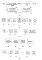
Figure 1 is a schematic diagram of the composition of an inverse channel apparatus of an embodiment of the present invention; -
Figures 2A and2B are schematic diagrams of the composition of two examples of an inverse nonlinear calculating unit of an embodiment of the present invention; -
Figure 3A and 3B are schematic diagrams of the composition of two examples of an inverse linear calculating unit of an embodiment of the present invention; -
Figure 4 is a schematic diagram of the composition of an inverse channel apparatus of a preferred embodiment of the present invention; -
Figure 5 is a schematic diagram of the composition of a receiver comprising one inverse channel apparatus of an embodiment of the present invention; -
Figure 6 is a schematic diagram of the composition of a receiver comprising a plurality of inverse channel apparatuses of an embodiment of the present invention; -
Figure 7 is a schematic diagram of the composition of a transmitter comprising one inverse channel apparatus of an embodiment of the present invention; -
Figure 8 is a schematic diagram of the composition of a transmitter comprising a plurality of inverse channel apparatuses of an embodiment of the present invention; -
Figure 9 is a schematic diagram of the composition of a transmission system of an embodiment of the present invention; -
Figure 10 is a schematic diagram of experimental performances of nonlinear compensation by using an inverse channel apparatus of an embodiment of the present invention; and -
Figure 11 is a flowchart of a nonlinear compensation method of an embodiment of the present invention. - The foregoing and other features of the embodiments of the present invention will become apparent with reference to the attached drawings and the following description. These embodiments are illustrative only, and are not intended to limit the present invention. For the easy understanding of the principle and embodiments of the present invention, the embodiments of the present invention shall be described taking an optical fiber communication system as an example. However, it should be understood that the embodiments of the present invention are not limited thereto, and any other transmission systems needing elimination of intra-channel damages (including linear and nonlinear damages) may use the apparatus provided by the embodiments of the present invention.
- Following description is given taking that an input signal contains two polarization states as an example. However, it should be understood that the embodiments of the present invention are not limited thereto. When an input signal contains only one polarization state, for example, H polarization state or V polarization state, linear damage and nonlinear damage may also be performed by the inverse channel apparatus of the embodiments of the present invention.
- An inverse channel apparatus, a receiver comprising the inverse channel apparatus, a transmitter comprising the inverse channel apparatus and a transmission system comprising the inverse channel apparatus shall be described below with reference to the attached drawings.
- An embodiment of the present invention provides an inverse channel apparatus.
Fig. 1 is a schematic diagram of the composition of the inverse channel apparatus. Referring toFig. 1 , the inverse channel apparatus comprises: an inverse nonlinear calculatingunit 101 and an inverse linear calculatingunit 102, wherein
the inverse nonlinear calculatingunit 101 is configured to perform nonlinear additive calculation and nonlinear multiplicative calculation on input signals, so as to obtain signals containing nonlinear damage of the input signals on at least one polarization state; and
the inverse linear calculatingunit 102 is configured to calculate signals containing nonlinear damage and linear damage of the input signals on at least one polarization state according to the signals containing nonlinear damage of the input signals on at least one polarization state and a linear function of a channel. - In this embodiment, the input signals may comprise signals of two polarization states, and may also comprise signals of only one polarization state. When the input signals comprise signals of two polarization states, signals containing nonlinear damage of the input signals on the two polarization states may be obtained by the inverse nonlinear calculating
unit 101. For example, when the input signals comprise a signal H on horizontal polarization state and a signal V on vertical polarization state, HNL and VNL may be obtained by using the inverse nonlinear calculatingunit 101; where HNL is a signal containing nonlinear damage of the signal H on the horizontal polarization state, and VNL is a signal containing nonlinear damage of the signal V on the vertical polarization state. When the input signals comprise signals of only one polarization state, signals containing nonlinear damage of the input signals on the polarization state may be obtained by using the inverse nonlinear calculatingunit 101. For example, when the input signals only comprise a signal H of horizontal polarization state, corresponding to that signal V of the input signals on vertical polarization state is 0, HNL is a signal containing nonlinear damage of the signal H on the horizontal polarization state may be obtained by using the inverse nonlinear calculatingunit 101. - In an embodiment, as the channel configuration parameters of an original channel are known, the inverse nonlinear calculating
unit 101 of this embodiment may be implemented by the composition as shown inFig. 2A . Referring toFig. 2A , the inverse nonlinear calculatingunit 101 comprises: an inverse nonlinearcoefficient calculating module 201, an inverse nonlinearperturbation calculating module 202 and an inverse nonlinear adding and multiplyingmodule 203; wherein,
the inverse nonlinearcoefficient calculating module 201 is configured to calculate nonlinear coefficients of the inverse channel according to the channel configuration parameters;
the inverse nonlinearperturbation calculating module 202 is configured to calculate nonlinear perturbation within the inverse channel according to the nonlinear coefficients of the inverse channel and the input signals; and
the inverse nonlinear adding and multiplyingmodule 203 is configured to calculate signals containing nonlinear damage of the input signals on at least one polarization state according to the nonlinear perturbation within the inverse channel and the input signals. - In an embodiment, the inverse nonlinear
coefficient calculating module 201 may calculate nonlinear coefficients of the inverse channel in an existing method of calculating nonlinear coefficient. However, as the existing method of calculating nonlinear coefficient is used to calculate nonlinear coefficients of an original channel, and nonlinear coefficients of an inverse channel are calculated in this embodiment, in calculating nonlinear coefficients of an inverse channel by using an existing method of calculating nonlinear coefficient, the symbols of the channel configuration parameters of the original channel need to be inverted, that is, nonlinear coefficients of an inverse channel are calculated by using an existing method of calculating nonlinear coefficient and taking the inverted values of the symbols of the channel configuration parameters of the original channel as the channel configuration parameters of the inverse channel. - In this embodiment, the channel configuration parameters comprise mainly optical fiber parameters, and the optical fiber parameters may be any combination of an attenuation factor (α), a dispersion factor (β) and a nonlinear factor (y). The selection of a particular combination depends on the method of calculating nonlinear coefficient. For example, if the three optical fiber parameters are used in the method of calculating nonlinear coefficient, the symbols of the three optical fiber parameters are inverted first, and then the nonlinear coefficients of the inverse channel are calculated by using the method of calculating nonlinear coefficient.
- In this embodiment, as it is known that both Mecozzi's method (document of A. Meccozi et al., PTL, vol. 12, pp. 392-394, 2000) and Wei's method (document of X. Wei, Opt. Lett., vol. 31, pp. 2544-2546, 2006) may be used to calculate nonlinear coefficients of an original channel, the two method may be used to calculate the nonlinear coefficients of the inverse channel. Of course, in calculating the nonlinear coefficients of the inverse channel, the symbols of the used channel configuration parameters (such as optical fiber parameters) need to be inverted.
- In an embodiment, the inverse nonlinear
perturbation calculating module 202 may be used to calculate the nonlinear perturbation within the inverse channel caused by intra-channel four-wave mixing (IFWM), intra-channel cross phase modulation (IXPM) and self-phase modulation (SPM). - Wherein, the nonlinear perturbation caused by IFWM may be calculated by using the formula below:


- Wherein, the nonlinear perturbation caused by IXPM may be calculated by using the formula below:


- And wherein, the nonlinear perturbation caused by SPM may be calculated by using the formula below:

- In the above formulae, c is a nonlinear coefficient of the inverse channel, m and n are relative moments, l is an absolute moment, H is an input signal on the horizontal polarization state, and V is an input signal on the vertical polarization state. This embodiment is described taking calculation of nonlinear perturbation within the inverse channel by using the above formulae as an example. However, this embodiment is not limited thereto, and in the art and in the future developed technologies, all the methods of calculating nonlinear perturbation of an inverse channel are covered by the protection scope of the inverse nonlinear
perturbation calculating module 202 of the embodiment of the present invention. - In an embodiment, the inverse nonlinear adding and multiplying
module 203 may calculate the signals containing nonlinear damage of the input signals on at least one polarization state according to the following formula:
and may also calculate the signals containing nonlinear damage of the input signals on at least one polarization state according to the following formula:
and may also calculate the signals containing nonlinear damage of the input signals on at least one polarization state according to the following formula:
where, H is an input signal on the horizontal polarization state, V is an input signal on the vertical polarization state, Δh,IFWM and Δ v,IFWM are the nonlinear perturbation caused by IFWM, φ h,IXPM, φ v,IXPM , whv,IXPM and wvh,IXPM are the nonlinear perturbation caused by IXPM, and φ h,SPM and φ v,SPM are the nonlinear perturbation caused by SPM,
perturbation calculating module 202. - In this embodiment, the above formulae may also be referred to as additive-multiplicative models. These formulae are illustrative only, and any other calculation method and formulae eliminating nonlinear damage by performing additive and multiplicative calculation on input signals and nonlinear perturbation are all covered by the protection scope of the inverse nonlinear adding and multiplying
module 203 of the embodiment of the present invention. - In another embodiment, as the channel configuration parameters of an original channel are unknown, the composition of the inverse nonlinear calculating
unit 101 of this embodiment may be implemented as shown inFig. 2B . Referring toFig. 2B , besides the inverse nonlinearcoefficient calculating module 201, the inverse nonlinearperturbation calculating module 202 and the inverse nonlinear adding and multiplyingmodule 203, the inverse nonlinear calculatingunit 101 further comprises an optical fiberparameter estimating module 204. - In this embodiment, the optical fiber
parameter estimating module 204 estimates parameters (including an attenuation factor α and/or a dispersion factor β and/or a nonlinear factor γ) of an optical fiber channel by analyzing input signals, such as H and V, so as to provide to the nonlinear coefficient calculating module. The method for estimating optical fiber parameters can also be implemented by known technology, such as the methods described in the documents of L. Liu et al., OFC2009, paper JWA36 and J. C. Geyer et al., PTL, vol. 20, pp. 776-778, 2008, etc. - The above two schemes of implementation are just two examples of the inverse nonlinear calculating
unit 101. However, this embodiment is not limited thereto, and other composition capable of implementing the functions of the inverse nonlinear calculatingunit 101 is also covered by the protection scope of the present invention. - In an embodiment, the inverse linear calculating
unit 102 may be implemented by aninverse dispersion module 301 shown inFig. 3A . As shown inFig. 3A , theinverse dispersion module 301 calculates signals containing nonlinear damage and linear damage of the input signals on at least one polarization state according to the signals containing nonlinear damage of the input signals on at least one polarization state and a dispersion transfer function of the channel. - In this embodiment, the
inverse dispersion module 301 calculates signals containing nonlinear damage and linear damage of the input signals on at least one polarization state according to the following formula: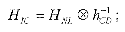

where, HIC is a signal containing nonlinear damage and linear damage of the input signals on the horizontal polarization state, and VIC is a signal containing nonlinear damage and linear damage of the input signals on the vertical polarization state; likewise, when the input signals have only one polarization state, a signal containing nonlinear damage and linear damage of the input signals on this polarization state may only be obtained by theinverse dispersion module 301; that is, only HIC or VIC is obtained;
where, HNL is a signal containing nonlinear damage of the input signals on the horizontal polarization state, and VNL is a signal containing nonlinear damage of the input signals on the vertical polarization state; and HNL and VNL are obtained through calculation by the above-described inverse nonlinear adding and multiplyingmodule 203 of the inverse nonlinear calculatingunit 101; likewise, when the input signals have only on polarization state, a signal containing nonlinear damage of the input signals on this polarization state may only be obtained by the inverse nonlinear adding and multiplyingmodule 203; that is, only HNL or VNL is obtained;
and where, hCD is a dispersion transfer function of the original channel,
- In another embodiment, the inverse linear calculating
unit 102 may be implemented by the composition as shown inFig. 3B . Referring toFig. 3B , besides theinverse dispersion module 301, the inverse linear calculatingunit 102 further comprises an inverse polarization mode dispersion (PMD)module 302. - In this embodiment, the relationship between the input signals and output signals of the
inverse PMD module 302 is:
where, HPMD is a PMD transmission matrix of the original channel, and
- The above two schemes of implementation are just two examples of the inverse linear calculating
unit 102. However, this embodiment is not limited thereto, and other composition capable of implementing the functions of the inverse linear calculatingunit 102 is also covered by the protection scope of the present invention. - In this embodiment, the inverse channel apparatus is applicable to but not limited to such modulation formats as mPSK, mQAM and mAPSK, and subcarrier multiplexing or OFDM technology.
-
Fig. 4 is a schematic diagram of the composition of an inverse channel apparatus of a preferred embodiment of the present invention. Referring toFig. 4 , the inverse channel apparatus comprises: an inverse nonlinearcoefficient calculating module 401, an inverse nonlinearperturbation calculating module 402, an inverse nonlinear adding and multiplyingmodule 403 and aninverse dispersion module 404. - Wherein, the inverse nonlinear
coefficient calculating module 401 may be implemented by the above-described inverse nonlinearcoefficient calculating module 201, the inverse nonlinearperturbation calculating module 402 may be implemented by the above-described inverse nonlinearperturbation calculating module 202, the inverse nonlinear adding and multiplyingmodule 403 may be implemented by the above-described inverse nonlinear adding and multiplyingmodule 203, and theinverse dispersion module 404 may be implemented by the above-describedinverse dispersion module 301. As the inverse nonlinearcoefficient calculating module 201, the inverse nonlinearperturbation calculating module 202, the inverse nonlinear adding and multiplyingmodule 203 and theinverse dispersion module 301 have been described above, they shall not be described any further. - With the inverse channel apparatus of the embodiment of the present invention, a transmitted signal is recovered in a receiver by being passed through the inverse channel apparatus of the embodiment of the present invention after or before being transmitted in a practical channel, and intra-channel damages (including linear and nonlinear damages) are eliminated, thereby effectively compensating for intra-channel nonlinear damage of an optical fiber communication system.
- An embodiment of the present invention further provides a receiver, comprising the inverse channel apparatus of the
Embodiment 1 of the present invention, in addition to original composition and functions. - In an embodiment, the receiver comprises one inverse channel apparatus of the
Embodiment 1 of the present invention, and the inverse channel apparatus is provided between an analog-to-digital converter and an adaptive equalization and polarization demultiplexer of the receiver. In this embodiment, the inverse channel apparatus is configured to build an inverse channel of whole of an original channel; that is, the inverse channel apparatus is configured to calculate each value by using parameters corresponding to the whole original channel. -
Fig. 5 is a schematic diagram of the composition of the receiver. Referring toFig. 5 , the receiver comprises: - a polarization diversity integrated
front end 501, an analog-to-digital converter 502, aninverse channel apparatus 503, an adaptive equalization andpolarization demultiplexing device 504, adeviation compensating device 505, a carrierphase recovering device 506 and adata recovering device 507. - Wherein, the polarization diversity integrated
front end 501, the analog-to-digital converter 502, the adaptive equalization andpolarization demultiplexing device 504, thedeviation compensating device 505, the carrierphase recovering device 506 and thedata recovering device 507 may be implemented in an existing scheme, and the contents of which are incorporated herein, and shall not be described any further. - And wherein the
inverse channel apparatus 503 may be implemented by theinverse channel apparatus 1 ofEmbodiment 1, and the description of it is omitted herein. - In another embodiment, the receiver comprises a plurality of inverse channel apparatuses provided by the
Embodiment 1 of the present invention, and the inverse channel apparatuses are also provided between the analog-to-digital converter and the adaptive equalization and polarization demultiplexer of the receiver. In this embodiment, each of the inverse channel apparatuses (5031-503N) is configured to build an inverse channel of a part of an original channel; that is, each of the inverse channel apparatuses is configured to calculate each value by using parameters corresponding to part of the original channel. In this embodiment, it corresponds to that theinverse channel apparatus 503 ofFig. 5 is disassembled into N cascaded units; that is, an inverse channel of only a part of the original channel is constructed each time, and then the inverse channel of the whole original channel is constructed in a cascaded scheme, as shown inFig. 6 . In this embodiment, as the whole inverse channel is disassembled, the nonlinear effect contained in each unit of the inverse channel is weakened, thereby improving the accuracy of the perturbation analysis. An extreme example is to take each span of an optical fiber as a cascade for constructing an inverse channel, without using an additive-multiplicative model and taking phase noise of the SPM into consideration only, and the structure ofFig. 6 is degraded into a known BP technology (document of E. Ip et al., JLT, vol. 26, pp.3416-3425, 2008). - The receiver of the embodiment of the present invention uses the inverse channel apparatus, in which a transmitted signal is recovered in the receiver by being passed through the inverse channel apparatus after being transmitted in a practical channel, and intra-channel damages (including linear and nonlinear damages) are eliminated, thereby effectively compensating for intra-channel nonlinear damage of an optical fiber communication system.
- An embodiment of the present invention further provides a transmitter, comprising the inverse channel apparatus of the
Embodiment 1 of the present invention, in addition to original composition and functions. - In an embodiment, the transmitter comprises one inverse channel apparatus of the
Embodiment 1 of the present invention, and the inverse channel apparatus is provided before an digital-to-analog converter of the transmitter. In this embodiment, the inverse channel apparatus is configured to build an inverse channel of whole of an original channel; that is, the inverse channel apparatus is configured to calculate each value by using parameters corresponding to the whole original channel. -
Fig. 7 is a schematic diagram of the composition of the transmitter. Referring toFig. 7 , the transmitter comprises: - a
mode generating device 701, aninverse channel apparatus 702, an digital-to-analog converter 703 and amodulator 704. - Wherein, the
mode generating device 701, the digital-to-analog converter 703 and themodulator 704 may be implemented in an existing scheme, and the contents of which are incorporated herein, and shall not be described any further. - And wherein the
inverse channel apparatus 702 may be implemented by theinverse channel apparatus 1 ofEmbodiment 1, and the description of it is omitted herein. - In another embodiment, the transmitter comprises a plurality of inverse channel apparatuses provided by the
Embodiment 1 of the present invention, and the inverse channel apparatuses are also provided before the digital-to-analog converter of the transmitter. In this embodiment, each of the inverse channel apparatuses (7021-702N) is configured to build an inverse channel of a part of an original channel; that is, each of the inverse channel apparatuses is configured to calculate each value by using parameters corresponding to part of the original channel. In this embodiment, it corresponds to that theinverse channel apparatus 702 ofFig. 7 is disassembled into N cascaded units; that is, an inverse channel of only a part of the original channel is constructed each time, and then the inverse channel of the whole original channel is constructed in a cascaded scheme, as shown inFig. 8 . In this embodiment, as the whole inverse channel is disassembled, the nonlinear effect contained in each unit of the inverse channel is weakened, thereby improving the accuracy of the perturbation analysis. An extreme example is to take each span of an optical fiber as a cascade for constructing an inverse channel, without using an additive-multiplicative model and taking phase noise of the SPM into consideration only, and the structure ofFig. 8 is degraded into a known BP technology (document of E. Ip et al., JLT, vol. 26, pp.3416-3425, 2008). - The transmitter of the embodiment of the present invention uses the inverse channel apparatus, in which a transmitted signal is recovered in the receiver by being passed through the inverse channel apparatus after being transmitted in a practical channel, and intra-channel damages (including linear and nonlinear damages) are eliminated, thereby effectively compensating for intra-channel nonlinear damage of an optical fiber communication system.
- An embodiment of the present invention further provides a transmission system.
Fig. 9 is a schematic diagram of the composition of the transmission system. Referring toFig. 9 , the transmission system comprises atransmitter 901 and areceiver 902, wherein
thetransmitter 901 or thereceiver 902 comprises one or more inverse channel apparatuses ofEmbodiment 1. - In an embodiment, the
transmitter 901 comprises one or a plurality of inverse channel apparatuses ofEmbodiment 1. When one inverse channel apparatus is included, the inverse channel apparatus builds an inverse channel of a whole original channel. And when a plurality of inverse channel apparatuses are included, each of the inverse channel apparatuses builds an inverse channel of a part of the whole original channel, and all the inverse channel apparatuses build an inverse channel of the whole original channel. - In another embodiment, the
receiver 902 comprises one or a plurality of inverse channel apparatuses ofEmbodiment 1. When one inverse channel apparatus is included, the inverse channel apparatus builds an inverse channel of a whole original channel. And when a plurality of inverse channel apparatuses are included, each of the inverse channel apparatuses builds an inverse channel of a part of the whole original channel, and all the inverse channel apparatuses build an inverse channel of the whole original channel. - In another embodiment, both the
transmitter 901 and thereceiver 902 comprise one or a plurality of inverse channel apparatuses ofEmbodiment 1. Each of the inverse channel apparatuses builds an inverse channel of a part of the whole original channel, and all the inverse channel apparatuses build an inverse channel of the whole original channel. For example, the transmitter and the receiver respectively builds an inverse channel of a half of an optical fiber transmission channel by one or a plurality of inverse channel apparatuses ofEmbodiment 1, which can also achieve an effect of compensating for a whole optical fiber transmission channel. - In this embodiment, the transmission system may be an optical fiber communication transmission system, and may also be other transmission systems needing nonlinear compensation, and this embodiment is not limited thereto.
- The transmission system of the embodiment of the present invention uses the inverse channel apparatus, in which a transmitted signal is recovered in the receiver by being passed through the inverse channel apparatus before and/or after being transmitted in a practical channel, and intra-channel damages (including linear and nonlinear damages) are eliminated, thereby effectively compensating for intra-channel nonlinear damage of an optical fiber communication system.
-
Fig. 10 is a schematic diagram of comparison of performances of not using an inverse channel apparatus and using the inverse channel apparatus of the embodiment of the present invention in a typical long-haul coherent optical transmission experiment. It can be seen fromFig. 10 that the inverse channel apparatus of the embodiment of the present invention can effectively improve the performances of nonlinear compensation. - An embodiment of the present invention further provides a nonlinear compensation method.
Fig. 11 is a flowchart of the method. Referring toFig. 11 , the method comprises: - step 1101: performing nonlinear additive damage calculation and nonlinear multiplicative damage calculation on input signals entering into an inverse channel, so as to obtain signals containing nonlinear damage of the input signals on at least one polarization state; and
- step 1102: calculating signals containing nonlinear damage and linear damage of the input signals on at least one polarization state according to the signals containing nonlinear damage of the input signals on at least one polarization state and a linear function of a channel.
- In an embodiment, an inverse channel may be built by perturbation analysis of nonlinear effect, the nonlinear effect in the inverse channel may be indicated by a additive-multiplicative model (AM model), and then intra-channel nonlinear damage is calculated by using a perturbation method according to nonlinear coefficients. Mecozzi's method (document of A. Meccozi et al., PTL, vol. 12, pp. 392-394, 2000) or Wei's method (document of X. Wei, Opt. Lett., vol. 31, pp. 2544-2546, 2006) may be used for the calculation of the nonlinear coefficients. Wherein, a typical example of the AM model is as described in document "A calculation apparatus for intra-channel nonlinearly introduced noise", the inventor of which is Liang Dou, with the application No.
201110287852.X - In this embodiment, in
step 1101, the nonlinear coefficients of the inverse channel may be calculated first according to the channel configuration parameters of the inverse channel, then the nonlinear perturbation within the inverse channel is calculated according to the nonlinear coefficients of the inverse channel and the input signals, and finally signals containing nonlinear damage of the input signals on at least one polarization state are calculated according the nonlinear perturbation within the inverse channel and the input signals. - In an embodiment, the channel configuration parameters of the inverse channel comprise optical fiber parameters, the optical fiber parameters comprising an attenuation factor α and/or a dispersion factor β and/or a nonlinear factor γ; wherein the nonlinear coefficients of the inverse channel may be calculated according to inverted values of the optical fiber parameters.
- In an embodiment, the nonlinear perturbation within the inverse channel comprises nonlinear perturbation caused by intra-channel four-wave mixing (IFWM), intra-channel cross phase modulation (IXPM) and self-phase modulation (SPM);
and wherein,
the nonlinear perturbation caused by IFWM is:

the nonlinear perturbation caused by IXPM is:


and the nonlinear perturbation caused by SPM is:
where, c is a nonlinear coefficient of the inverse channel, m and n are relative moments, l is an absolute moment, H is an input signal on the horizontal polarization state, and V is an input signal on the vertical polarization state. - In an embodiment, the signals containing nonlinear damage of the input signals on at least one polarization state are calculated according to the following formula:

or
or
where, Δh,IFWM and Δ v,IFWM are the nonlinear perturbation caused by IFWM, φ h,IXPM, φ v,IXPM , whv,IXPM and wvh,IXPM are the nonlinear perturbation caused by IXPM, φ h,SPM and φ v,SPM are the nonlinear perturbation caused by SPM,

- In an embodiment, the signals containing nonlinear damage and linear damage of the input signals on at least one polarization state are obtained by calculating according to the signals containing nonlinear damage of the input signals on at least one polarization state and a dispersion transfer function of the channel;
and wherein the signals containing nonlinear damage and linear damage of the input signals on at least one polarization state are calculated according to the following formula:

- The above formulae and calculation methods are illustrative only, and the embodiments of the present invention are not limited to particular manners of implementation. All the methods carrying out the above-described functions according to the above description are covered by the protection scope of the embodiments of the present invention.
- The method of the embodiment of the present invention may be applicable to compensation for nonlinear damage of a whole optical fiber transmission channel (original channel), and also to compensation for nonlinear damage of part of an optical fiber transmission channel (original channel). However, this embodiment is not limited thereto. A particular difference mainly exists in the used channel configuration parameters, such as a length of an optical fiber in optical fiber parameters, etc.
- In the method of the embodiment of the present invention, by building inversion of a channel (i.e. an inverse channel), a transmitted signal is recovered in a receiver by being passed through the inverse channel after or before being transmitted in a practical channel, and intra-channel damages, including linear and nonlinear damages, are eliminated.
- The preferred embodiments of the present invention are described above with reference to the drawings. The many features and advantages of the embodiments are apparent from the detailed specification and, thus, it is intended by the appended claims to cover all such features and advantages of the embodiments that fall within the true spirit and scope thereof. Further, since numerous modifications and changes will readily occur to those skilled in the art, it is not desired to limit the inventive embodiments to the exact construction and operation illustrated and described, and accordingly all suitable modifications and equivalents may be resorted to, falling within the scope thereof.
- It should be understood that each of the parts of the present invention may be implemented by hardware, software, firmware, or a combination thereof. In the above embodiments, multiple steps or methods may be realized by software or firmware that is stored in the memory and executed by an appropriate instruction executing system. For example, if it is realized by hardware, it may be realized by any one of the following technologies known in the art or a combination thereof as in another embodiment: a discrete logic circuit having a logic gate circuit for realizing logic functions of data signals, application-specific integrated circuit having an appropriate combined logic gate circuit, a programmable gate array (PGA), and a field programmable gate array (FPGA), etc.
- The description or blocks in the flowcharts or of any process or method in other manners may be understood as being indicative of comprising one or more modules, segments or parts for realizing the codes of executable instructions of the steps in specific logic functions or processes, and that the scope of the preferred embodiments of the present invention comprise other implementations, wherein the functions may be executed in manners different from those shown or discussed, including executing the functions according to the related functions in a substantially simultaneous manner or in a reverse order, which should be understood by those skilled in the art to which the present invention pertains.
- The logic and/or steps shown in the flowcharts or described in other manners here may be, for example, understood as a sequencing list of executable instructions for realizing logic functions, which may be implemented in any computer readable medium, for use by an instruction executing system, device or apparatus (such as a system including a computer, a system including a processor, or other systems capable of extracting instructions from an instruction executing system, device or apparatus and executing the instructions), or for use in combination with the instruction executing system, device or apparatus. As used herein, "a computer readable medium" can be any device that can contain, store, communicate with, propagate or transmit programs for use by an instruction executing system, device or apparatus, or can be used with the instruction executing system, device or apparatus. A computer readable medium may be, for example, but not limited to, a magnetic, optical, electromagnetic, infrared or semiconductor system, device, apparatus, or a propagation medium. More particular examples (inexhaustive lists) of a computer readable medium may comprise the following: an electrical connecting portion (electronic device) having one or more wirings, a portable computer hardware box (magnetic device), a random access memory (RAM) (electronic device), a read-only memory (ROM) (electronic device), an erasable programmable read-only memory (EPROM or flash memory) (electronic device), an optical fiber (optical device), and a portable compact disk read-only memory (CDROM) (optical device). Furthermore, a computer readable medium may be paper or other appropriate media on which the programs may be printed, as the programs may be obtained electronically through scanning optically the paper or other appropriate media and then compiling, interpreting, or processing in other appropriate manners, as necessary, and then the programs are stored in the computer memory.
- The above literal description and drawings show various features of the present invention. It should be understood that a person of ordinary skill in the art may prepare suitable computer codes to carry out each of the steps and processes described above and illustrated in the drawings. It should also be understood that the above-described terminals, computers, servers, and networks, etc. may be any type, and the computer codes may be prepared according to the disclosure contained herein to carry out the present invention by using the devices.
- Particular embodiments of the present invention have been disclosed herein. Those skilled in the art will readily recognize that the present invention is applicable in other environments. In practice, there exist many embodiments and implementations. The appended claims are by no means intended to limit the scope of the present invention to the above particular embodiments. Furthermore, any reference to "a device to..." is an explanation of device plus function for describing elements and claims, and it is not desired that any element using no reference to "a device to..." is understood as an element of device plus function, even though the wording of "device" is included in that claim.
- Although a particular preferred embodiment or embodiments have been shown and the present invention has been described, it is obvious that equivalent modifications and variants are conceivable to those skilled in the art in reading and understanding the description and drawings. Especially for various functions executed by the above elements (portions, assemblies, apparatus, and compositions, etc.), except otherwise specified, it is desirable that the terms (including the reference to "device") describing these elements correspond to any element executing particular functions of these elements (i.e. functional equivalents), even though the element is different from that executing the function of an exemplary embodiment or embodiments illustrated in the present invention with respect to structure. Furthermore, although the a particular feature of the present invention is described with respect to only one or more of the illustrated embodiments, such a feature may be combined with one or more other features of other embodiments as desired and in consideration of advantageous aspects of any given or particular application.
- For the implementation of the present invention containing the above embodiments, following supplements are further disclosed.
-
Supplement 1. An inverse channel apparatus, comprising:- an inverse nonlinear calculating unit configured to perform nonlinear additive calculation and nonlinear multiplicative calculation on input signals, so as to obtain signals containing nonlinear damage of the input signals on at least one polarization state; and
- an inverse linear calculating unit configured to calculate signals containing nonlinear damage and linear damage of the input signals on at least one polarization state according to the signals containing nonlinear damage of the input signals on at least one polarization state and a linear function of a channel.
-
Supplement 2. The apparatus according tosupplement 1, wherein the inverse nonlinear calculating unit comprises:- an inverse nonlinear coefficient calculating module configured to calculate nonlinear coefficients of the inverse channel according to channel configuration parameters;
- an inverse nonlinear perturbation calculating module configured to calculate nonlinear perturbation within the inverse channel according to the nonlinear coefficients of the inverse channel and the input signals; and
- an inverse nonlinear adding and multiplying module configured to calculate signals containing nonlinear damage of the input signals on at least one polarization state according to the nonlinear perturbation within the inverse channel and the input signals.
- Supplement 3. The apparatus according to
supplement 2, wherein the channel configuration parameters comprise optical fiber parameters, the optical fiber parameters comprising an attenuation factor α and/or a dispersion factor β and/or a nonlinear factor γ;
and wherein the inverse nonlinear coefficient calculating module calculates the nonlinear coefficients of the inverse channel according to inverted values of the optical fiber parameters. -
Supplement 4. The apparatus according tosupplement 2, wherein the inverse nonlinear perturbation calculating module is configured to calculate nonlinear perturbation within the inverse channel caused by intra-channel four-wave mixing (IFWM), intra-channel cross phase modulation (IXPM) and self-phase modulation (SPM);
and wherein,
the nonlinear perturbation caused by IFWM is:

the nonlinear perturbation caused by IXPM is:


and the nonlinear perturbation caused by SPM is:
where, c is a nonlinear coefficient of the inverse channel, m and n are relative moments, l is an absolute moment, H is an input signal on the horizontal polarization state, and V is an input signal on the vertical polarization state. - Supplement 5. The apparatus according to
Supplement 2, wherein the inverse nonlinear adding and multiplying module calculates the signals containing nonlinear damage of the input signals on at least one polarization state according to the following formula:
or
or
where, Δh,IFWM and Δ v,IFWM are the nonlinear perturbation caused by IFWM, φ h,IXPM, φ v,IXPM , whv,IXPM and wvh,IXPM are the nonlinear perturbation caused by IXPM, φ h,SPM and φ v,SPM are the nonlinear perturbation caused by SPM,

-
Supplement 6. The apparatus according tosupplement 1, wherein
the inverse linear calculating unit is an inverse dispersion unit which calculates signals containing nonlinear damage and linear damage of the input signals on at least one polarization state according to the signals containing nonlinear damage of the input signals on at least one polarization state and a dispersion transfer function of the channel;
and wherein the inverse dispersion unit calculates signals containing nonlinear damage and linear damage of the input signals on at least one polarization state according to the following formula:

- Supplement 7. A receiver, comprising one or a plurality of inverse channel apparatuses as described in any one of supplements 1-6, wherein
when the receiver comprises one inverse channel apparatuses, the inverse channel apparatus is provided between an analog-to-digital converter and an adaptive equalization and polarization demultiplexer of the receiver, the inverse channel apparatus being configured to build an inverse channel of an original channel;
and when the receiver comprises a plurality of inverse channel apparatuses, the inverse channel apparatuses are provided between the analog-to-digital converter and the adaptive equalization and polarization multiplexer of the receiver, each of the inverse channel apparatuses being configured to build inverse channels of a part of original channels. - Supplement 8. A transmitter, comprising one or a plurality of inverse channel apparatuses as described in any one of supplements 1-6, wherein
when the transmitter comprises one inverse channel apparatus, the inverse channel apparatus is provided before an digital-to-analog converter of the transmitter, the inverse channel apparatus being configured to build an inverse channel of an original channel;
and when the transmitter comprises a plurality of inverse channel apparatuses, the inverse channel apparatuses are provided before the digital-to-analog converter of the transmitter, each of the inverse channel apparatuses being configured to build inverse channels of a part of original channels. - Supplement 9. A transmission system, comprising a transmitter and a receiver, the transmitter or receiver comprising one or a plurality of the inverse channel apparatuses as described in any one of supplements 1-6.
10. A nonlinear compensation method, comprising:- performing nonlinear additive damage calculation and nonlinear multiplicative damage calculation on input signals, so as to obtain signals containing nonlinear damage of the input signals on at least one polarization state; and
- calculating signals containing nonlinear damage and linear damage of the input signals on at least one polarization state according to the signals containing nonlinear damage of the input signals on at least one polarization state and a linear function of a channel.
- Supplement 11. The method according to supplement 10, wherein the nonlinear coefficients of the inverse channel may be calculated first according to the channel configuration parameters of the inverse channel, then the nonlinear perturbation within the inverse channel is calculated according to the nonlinear coefficients of the inverse channel and the input signals, and finally signals containing nonlinear damage of the input signals on at least one polarization state are calculated according the nonlinear perturbation within the inverse channel and the input signals.
-
Supplement 12. The method according to supplement 11, wherein the channel configuration parameters of the inverse channel comprise optical fiber parameters, the optical fiber parameters comprising an attenuation factor α and/or a dispersion factor β and/or a nonlinear factor γ; wherein the nonlinear coefficients of the inverse channel may be calculated according to inverted values of the optical fiber parameters. - Supplement 13. The method according to supplement 11, wherein the nonlinear perturbation within the inverse channel comprises nonlinear perturbation caused by intra-channel four-wave mixing (IFWM), intra-channel cross phase modulation (IXPM) and self-phase modulation (SPM);
and wherein,
the nonlinear perturbation caused by IFWM is:

the nonlinear perturbation caused by IXPM is:



and the nonlinear perturbation caused by SPM is:
where, c is a nonlinear coefficient of the inverse channel, m and n are relative moments, l is an absolute moment, H is an input signal on the horizontal polarization state, and V is an input signal on the vertical polarization state. - Supplement 14. The method according to supplement 11, wherein the signals containing nonlinear damage of the input signals on at least one polarization state are calculated according to the following formula:

or
or
where, Δ h,IFWM and Δ v,IFWM are the nonlinear perturbation caused by IFWM, φ h,IXPM, φ v,IXPM , whv,IXPM and wvh,IXPM are the nonlinear perturbation caused by IXPM, φ h,SPM and φ v,SPM are the nonlinear perturbation caused by SPM,

- Supplement 15. The method according to supplement 11, wherein the signals containing nonlinear damage and linear damage of the input signals on at least one polarization state are obtained by calculating according to the signals containing nonlinear damage of the input signals on at least one polarization state and a dispersion transfer function of the channel;
and wherein the signals containing nonlinear damage and linear damage of the input signals on at least one polarization state are calculated according to the following formula: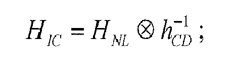

Claims (10)
- An inverse channel apparatus, comprising:an inverse nonlinear calculating unit configured to perform nonlinear additive calculation and nonlinear multiplicative calculation on input signals, so as to obtain signals containing nonlinear damage of the input signals on at least one polarization state; andan inverse linear calculating unit configured to calculate signals containing nonlinear damage and linear damage of the input signals on at least one polarization state according to the signals containing nonlinear damage of the input signals on at least one polarization state and a linear function of a channel.
- The apparatus according to claim 1, wherein the inverse nonlinear calculating unit comprises:an inverse nonlinear coefficient calculating module configured to calculate nonlinear coefficients of the inverse channel according to channel configuration parameters;an inverse nonlinear perturbation calculating module configured to calculate nonlinear perturbation within the inverse channel according to the nonlinear coefficients of the inverse channel and the input signals; andan inverse nonlinear adding and multiplying module configured to calculate signals containing nonlinear damage of the input signals on at least one polarization state according to the nonlinear perturbation within the inverse channel and the input signals.
- The apparatus according to claim 2, wherein the channel configuration parameters comprise optical fiber parameters, the optical fiber parameters comprising an attenuation factor α and/or a dispersion factor β and/or a nonlinear factor γ;
and wherein the inverse nonlinear coefficient calculating module calculates the nonlinear coefficients of the inverse channel according to inverted values of the optical fiber parameters. - The apparatus according to claim 2, wherein the inverse nonlinear perturbation calculating module is configured to calculate nonlinear perturbation within the inverse channel caused by intra-channel four-wave mixing (IFWM), intra-channel cross phase modulation (IXPM) and self-phase modulation (SPM);
and wherein,
the nonlinear perturbation caused by IFWM is:

the nonlinear perturbation caused by IXPM is:


and the nonlinear perturbation caused by SPM is:

where, c is a nonlinear coefficient of the inverse channel, m and n are relative moments, l is an absolute moment, H is an input signal on the horizontal polarization state, and V is an input signal on the vertical polarization state. - The apparatus according to claim 2, wherein the inverse nonlinear adding and multiplying module calculates the signals containing nonlinear damage of the input signals on at least one polarization state according to the following formula:

or
or
where, Δh,IFWM and Δ v,IFWM are the nonlinear perturbation caused by IFWM, φ h,IXPM, φ v,IXPM , whv,IXPM and wvh,IXPM are the nonlinear perturbation caused by IXPM, φ h,SPM and φ v,SPM, are the nonlinear perturbation caused by SPM,

- The apparatus according to claim 1, wherein
the inverse linear calculating unit is an inverse dispersion unit which calculates signals containing nonlinear damage and linear damage of the input signals on at least one polarization state according to the signals containing nonlinear damage of the input signals on at least one polarization state and a dispersion transfer function of the channel;
and wherein the inverse dispersion unit calculates signals containing nonlinear damage and linear damage of the input signals on at least one polarization state according to the following formula:

- A receiver, comprising one or a plurality of inverse channel apparatuses as claimed in any one of claims 1-6, wherein
when the receiver comprises one inverse channel apparatuses, the inverse channel apparatus is provided between an analog-to-digital converter and an adaptive equalization and polarization demultiplexer of the receiver, the inverse channel apparatus being configured to build an inverse channel of an original channel;
and when the receiver comprises a plurality of inverse channel apparatuses, the inverse channel apparatuses are provided between the analog-to-digital converter and the adaptive equalization and polarization multiplexer of the receiver, each of the inverse channel apparatuses being configured to build inverse channels of a part of original channels. - A transmitter, comprising one or a plurality of inverse channel apparatuses as claimed in any one of claims 1-6, wherein
when the transmitter comprises one inverse channel apparatus, the inverse channel apparatus is provided before an digital-to-analog converter of the transmitter, the inverse channel apparatus being configured to build an inverse channel of an original channel;
and when the transmitter comprises a plurality of inverse channel apparatuses, the inverse channel apparatuses are provided before the digital-to-analog converter of the transmitter, each of the inverse channel apparatuses being configured to build inverse channels of a part of original channels. - A transmission system, comprising a transmitter and a receiver, the transmitter or receiver comprising one or a plurality of the inverse channel apparatuses as claimed in any one of claims 1-6.
- A nonlinear compensation method, comprising:performing nonlinear additive damage calculation and nonlinear multiplicative damage calculation on input signals, so as to obtain signals containing nonlinear damage of the input signals on at least one polarization state; andcalculating signals containing nonlinear damage and linear damage of the input signals on at least one polarization state according to the signals containing nonlinear damage of the input signals on at least one polarization state and a linear function of a channel.
Applications Claiming Priority (1)
| Application Number | Priority Date | Filing Date | Title |
|---|---|---|---|
| CN201210071581.9A CN103312414B (en) | 2012-03-16 | 2012-03-16 | A kind of inverse channel device and comprise the transmitter of this device, receiver and system |
Publications (2)
| Publication Number | Publication Date |
|---|---|
| EP2639976A1 true EP2639976A1 (en) | 2013-09-18 |
| EP2639976B1 EP2639976B1 (en) | 2018-04-25 |
Family
ID=47843122
Family Applications (1)
| Application Number | Title | Priority Date | Filing Date |
|---|---|---|---|
| EP13158130.8A Not-in-force EP2639976B1 (en) | 2012-03-16 | 2013-03-07 | Inverse channel apparatus and transmitter, receiver and system containing the apparatus |
Country Status (3)
| Country | Link |
|---|---|
| US (1) | US8995835B2 (en) |
| EP (1) | EP2639976B1 (en) |
| CN (1) | CN103312414B (en) |
Cited By (3)
| Publication number | Priority date | Publication date | Assignee | Title |
|---|---|---|---|---|
| JP2017225024A (en) * | 2016-06-16 | 2017-12-21 | 富士通株式会社 | Receiving device and setting method |
| WO2018075239A1 (en) * | 2016-10-17 | 2018-04-26 | Panduit Corp. | Methods and systems for fiber optic communication |
| US20220116113A1 (en) * | 2019-06-21 | 2022-04-14 | Fraunhofer-Gesellschaft zur Förderung der angewandten Forschung e.V. | Apparatus and method for transmitting and/or receiving data over a fiber-optical channel employing perturbation-based fiber nonlinearity compensation in a periodic frequency domain |
Families Citing this family (11)
| Publication number | Priority date | Publication date | Assignee | Title |
|---|---|---|---|---|
| US9831956B2 (en) * | 2013-02-07 | 2017-11-28 | Nec Corporation | Signal processing device and signal processing method |
| US9853765B2 (en) * | 2013-04-09 | 2017-12-26 | Nec Corporation | Signal processing device and signal processing method for optical polarization multiplexed signal |
| EP2804334A1 (en) * | 2013-05-13 | 2014-11-19 | Xieon Networks S.à.r.l. | Method, device and communication system for reducing optical transmission impairments |
| US20150086193A1 (en) * | 2013-09-20 | 2015-03-26 | Alcatel-Lucent Usa Inc. | Fiber-nonlinearity pre-compensation processing for an optical transmitter |
| CN104980379B (en) * | 2014-04-11 | 2018-06-08 | 富士通株式会社 | Estimation device, method and the receiver of non-linear distortion |
| CN105827321B (en) * | 2015-01-05 | 2018-06-01 | 富士通株式会社 | Non-linear compensation method, device and system in multi-carrier light communication system |
| CN110380789B (en) * | 2018-04-12 | 2022-03-11 | 中兴通讯股份有限公司 | Signal processing method and device |
| US10985951B2 (en) | 2019-03-15 | 2021-04-20 | The Research Foundation for the State University | Integrating Volterra series model and deep neural networks to equalize nonlinear power amplifiers |
| US10756822B1 (en) | 2019-08-27 | 2020-08-25 | Nokia Solutions And Networks Oy | Digital fiber nonlinearity compensation |
| CN110784237B (en) * | 2019-10-30 | 2021-04-06 | 电子科技大学 | A device and method for improving the spurious-free dynamic range of a receiver |
| KR102275351B1 (en) * | 2020-05-07 | 2021-07-09 | 한국과학기술원 | Apparatus and method for nonlinear equalization based on absolute operation |
Citations (1)
| Publication number | Priority date | Publication date | Assignee | Title |
|---|---|---|---|---|
| US20100239262A1 (en) * | 2009-03-20 | 2010-09-23 | University Of Central Florida Research Foundation, Inc. | Compensation of Optical Transmission Impairments Using Digital Backward Propagation |
Family Cites Families (23)
| Publication number | Priority date | Publication date | Assignee | Title |
|---|---|---|---|---|
| US5226060A (en) * | 1992-01-08 | 1993-07-06 | Universal Data Systems, Inc. | Modem receiver with nonlinear equalization |
| US9191117B2 (en) * | 1995-05-11 | 2015-11-17 | Ciena Corporation | High-speed optical transponder systems |
| DE69728651T2 (en) * | 1996-11-19 | 2004-08-19 | Matsushita Electric Industrial Co., Ltd., Kadoma | Transmitter with linearized amplifier |
| EP1461879A2 (en) * | 2001-12-31 | 2004-09-29 | 3M Innovative Properties Company | System for higher-order dispersion compensation |
| JP3707549B2 (en) * | 2002-03-22 | 2005-10-19 | 日本電気株式会社 | Transmitter |
| US7266310B1 (en) * | 2003-04-29 | 2007-09-04 | Nortel Networks Limited | Digital compensation for optical transmission system |
| JP4394409B2 (en) * | 2003-09-25 | 2010-01-06 | 株式会社日立国際電気 | Predistortion type amplifier with distortion compensation function |
| US7430248B2 (en) * | 2004-01-27 | 2008-09-30 | Crestcom, Inc. | Predistortion circuit and method for compensating nonlinear distortion in a digital RF communications transmitter |
| JP4199185B2 (en) * | 2004-03-01 | 2008-12-17 | パナソニック株式会社 | Transmitting apparatus and wireless communication apparatus |
| US7606539B2 (en) * | 2006-08-07 | 2009-10-20 | Infineon Technologies Ag | Adaptive predistorter coupled to a nonlinear element |
| EP2086130B1 (en) * | 2008-01-29 | 2013-01-09 | Alcatel Lucent | Combined phase and polarization modulation for optical communication |
| JP5176692B2 (en) * | 2008-05-28 | 2013-04-03 | 日本電気株式会社 | Distortion compensation circuit and distortion compensation method |
| JP5088271B2 (en) * | 2008-08-19 | 2012-12-05 | 富士通株式会社 | Distortion compensator, optical receiver, control method thereof, and optical transmission system |
| US8233809B2 (en) * | 2008-10-28 | 2012-07-31 | Nec Laboratories America, Inc. | Polarization independent frequency domain equalization (FDE) for chromatic dispersion (CD) compensation in PolMux coherent systems |
| JP2010130071A (en) * | 2008-11-25 | 2010-06-10 | Fujitsu Ltd | Nonlinear distortion compensation apparatus and nonlinear distortion compensation method |
| EP2249493B1 (en) * | 2009-05-05 | 2013-12-18 | Alcatel Lucent | Method and equipment for operating a coherent optical packet receiver |
| US8943112B2 (en) * | 2009-06-26 | 2015-01-27 | Syntropy Systems, Llc | Sampling/quantization converters |
| CN102612811B (en) * | 2010-02-20 | 2016-03-30 | 华为技术有限公司 | Clock phase recovery device |
| US8494368B2 (en) * | 2010-04-16 | 2013-07-23 | Alcatel Lucent | Electronic nonlinearity compensation for optical transmission systems |
| KR20120065726A (en) * | 2010-12-13 | 2012-06-21 | 한국전자통신연구원 | Coherent optical receiver with digital equalization of the received optical signal and digital equalization method of the received digital signal |
| JP5671071B2 (en) * | 2011-02-07 | 2015-02-18 | 日本電信電話株式会社 | Digital signal processor |
| EP2502365B8 (en) * | 2011-02-17 | 2015-10-28 | Huawei Technologies Co., Ltd. | Signal processing apparatus, transmitter, receiver and method |
| US9680567B2 (en) * | 2011-03-03 | 2017-06-13 | Acacia Communications, Inc. | Fault localization and fiber security in optical transponders |
-
2012
- 2012-03-16 CN CN201210071581.9A patent/CN103312414B/en not_active Expired - Fee Related
-
2013
- 2013-03-05 US US13/785,366 patent/US8995835B2/en active Active
- 2013-03-07 EP EP13158130.8A patent/EP2639976B1/en not_active Not-in-force
Patent Citations (1)
| Publication number | Priority date | Publication date | Assignee | Title |
|---|---|---|---|---|
| US20100239262A1 (en) * | 2009-03-20 | 2010-09-23 | University Of Central Florida Research Foundation, Inc. | Compensation of Optical Transmission Impairments Using Digital Backward Propagation |
Non-Patent Citations (8)
| Title |
|---|
| A. MECCOZI ET AL., PTL, vol. 12, 2000, pages 392 - 394 |
| E. IP ET AL., JLT, vol. 26, 2008, pages 3416 - 3425 |
| E. IP ET AL., JOURNAL OF LIGHTWAVE TECHNOLOGY, vol. 26, 2008, pages 3416 - 3425, XP011241197 * |
| J. C. GEYER ET AL., PTL, vol. 20, 2008, pages 776 - 778 |
| L. LIU ET AL., OFC2009 |
| LING LIU ET AL: "Intrachannel Nonlinearity Compensation by Inverse Volterra Series Transfer Function", JOURNAL OF LIGHTWAVE TECHNOLOGY, IEEE SERVICE CENTER, NEW YORK, NY, US, vol. 30, no. 3, 1 February 2012 (2012-02-01), pages 310 - 316, XP011398582, ISSN: 0733-8724, DOI: 10.1109/JLT.2011.2182038 * |
| SHUXIAN SONG ET AL: "Numerically reversing the nonlinear wave propagation in single-mode optical fiber", IEEE LEOS 12TH ANNUAL MEETING CONFERENCE PROCEEDINGS. LEOS'99, IEEE, vol. 2, 8 November 1999 (1999-11-08), pages 611 - 612, XP010360969, ISBN: 978-0-7803-5634-4, DOI: 10.1109/LEOS.1999.811876 * |
| X. WEI, OPT. LETT., vol. 31, 2006, pages 2544 - 2546 |
Cited By (7)
| Publication number | Priority date | Publication date | Assignee | Title |
|---|---|---|---|---|
| JP2017225024A (en) * | 2016-06-16 | 2017-12-21 | 富士通株式会社 | Receiving device and setting method |
| EP3267600A3 (en) * | 2016-06-16 | 2018-04-18 | Fujitsu Limited | Receiving apparatus and setting method |
| US10541757B2 (en) | 2016-06-16 | 2020-01-21 | Fujitsu Limited | Receiving apparatus and setting method |
| WO2018075239A1 (en) * | 2016-10-17 | 2018-04-26 | Panduit Corp. | Methods and systems for fiber optic communication |
| US10020886B2 (en) | 2016-10-17 | 2018-07-10 | Panduit Corp. | Methods and systems for fiber optic communication |
| US20220116113A1 (en) * | 2019-06-21 | 2022-04-14 | Fraunhofer-Gesellschaft zur Förderung der angewandten Forschung e.V. | Apparatus and method for transmitting and/or receiving data over a fiber-optical channel employing perturbation-based fiber nonlinearity compensation in a periodic frequency domain |
| US11942994B2 (en) * | 2019-06-21 | 2024-03-26 | Fraunhofer-Gesellschaft zur Förderung der angewandten Forschung e. V. | Apparatus and method for transmitting and/or receiving data over a fiber-optical channel employing perturbation-based fiber nonlinearity compensation in a periodic frequency domain |
Also Published As
| Publication number | Publication date |
|---|---|
| EP2639976B1 (en) | 2018-04-25 |
| US8995835B2 (en) | 2015-03-31 |
| CN103312414A (en) | 2013-09-18 |
| US20130243433A1 (en) | 2013-09-19 |
| CN103312414B (en) | 2016-03-30 |
Similar Documents
| Publication | Publication Date | Title |
|---|---|---|
| EP2639976B1 (en) | Inverse channel apparatus and transmitter, receiver and system containing the apparatus | |
| EP2651084A2 (en) | Method and apparatus for compensating nonlinear distortions in intensity modulation-direct detection system | |
| EP3096470B1 (en) | Method and system for nonlinear interference mitigation | |
| Prilepsky et al. | Nonlinear spectral management: Linearization of the lossless fiber channel | |
| US20130108260A1 (en) | Method and apparatus for adaptive nonlinear equalization in a polarization multiplexing optical communication system | |
| Puttnam et al. | Self-homodyne detection in optical communication systems | |
| CN102386968B (en) | Self-phase modulation noise calculating device, removing device and optical coherent receiver | |
| EP2629471B1 (en) | Nonlinear Compensating Apparatus and Method and Transmitter | |
| JP6149367B2 (en) | Nonlinear estimation apparatus, method, and receiver | |
| Zuo et al. | Rogue waves for the generalized nonlinear Schrödinger–Maxwell–Bloch system in optical-fiber communication | |
| US20120290244A1 (en) | Method and apparatus for compensating nonlinear damage | |
| CN105471507A (en) | Nonlinear compensation method and device | |
| US9768884B2 (en) | Multi-range frequency-domain compensation of chromatic dispersion | |
| EP3076568B1 (en) | Method for eliminating nonlinear effect, transmitter and receiver | |
| Shu et al. | Low-complexity storage-reduced digital spectrum-based soft-failure management with Welch’s method | |
| US20120224867A1 (en) | Method and apparatus for all-optical discrete fourier transform including all-optical ofdm demultiplexing | |
| Chung et al. | Compensation of the distorted WDM signals by symmetric dispersion map with nonuniform zero-crossing place of accumulated dispersion in midway-OPC system | |
| Singh et al. | Joint-transceiver equalization technique over a 1.4 km multi-mode fiber using optical mimo technique in im/dd systems | |
| Vgenopoulou et al. | Comparison of nonlinear compensation techniques for 400-Gb/s coherent multi-band OFDM super-channels | |
| Asif et al. | Efficient compensation of chromatic dispersion and nonlinearities using logarithmic digital backward propagation in N-channel DWDM 1.12 Tbit/s DP-QPSK transmission | |
| Schmauss et al. | Progress in digital backward propagation | |
| Yang et al. | An integral split-step Fourier method for digital back propagation to compensate fiber nonlinearity | |
| JP6116001B2 (en) | Optical transmitter and optical receiver | |
| Xiao et al. | Learning effective nonlinear operator for high speed optical compensation system | |
| Zhou | All-optical discrete Fourier transform based on multilevel phase modulation and a dispersive element |
Legal Events
| Date | Code | Title | Description |
|---|---|---|---|
| PUAI | Public reference made under article 153(3) epc to a published international application that has entered the european phase |
Free format text: ORIGINAL CODE: 0009012 |
|
| AK | Designated contracting states |
Kind code of ref document: A1 Designated state(s): AL AT BE BG CH CY CZ DE DK EE ES FI FR GB GR HR HU IE IS IT LI LT LU LV MC MK MT NL NO PL PT RO RS SE SI SK SM TR |
|
| AX | Request for extension of the european patent |
Extension state: BA ME |
|
| 17P | Request for examination filed |
Effective date: 20140218 |
|
| RBV | Designated contracting states (corrected) |
Designated state(s): AL AT BE BG CH CY CZ DE DK EE ES FI FR GB GR HR HU IE IS IT LI LT LU LV MC MK MT NL NO PL PT RO RS SE SI SK SM TR |
|
| GRAP | Despatch of communication of intention to grant a patent |
Free format text: ORIGINAL CODE: EPIDOSNIGR1 |
|
| STAA | Information on the status of an ep patent application or granted ep patent |
Free format text: STATUS: GRANT OF PATENT IS INTENDED |
|
| INTG | Intention to grant announced |
Effective date: 20171121 |
|
| GRAA | (expected) grant |
Free format text: ORIGINAL CODE: 0009210 |
|
| GRAS | Grant fee paid |
Free format text: ORIGINAL CODE: EPIDOSNIGR3 |
|
| STAA | Information on the status of an ep patent application or granted ep patent |
Free format text: STATUS: THE PATENT HAS BEEN GRANTED |
|
| AK | Designated contracting states |
Kind code of ref document: B1 Designated state(s): AL AT BE BG CH CY CZ DE DK EE ES FI FR GB GR HR HU IE IS IT LI LT LU LV MC MK MT NL NO PL PT RO RS SE SI SK SM TR |
|
| REG | Reference to a national code |
Ref country code: GB Ref legal event code: FG4D |
|
| REG | Reference to a national code |
Ref country code: CH Ref legal event code: EP |
|
| REG | Reference to a national code |
Ref country code: AT Ref legal event code: REF Ref document number: 993936 Country of ref document: AT Kind code of ref document: T Effective date: 20180515 |
|
| REG | Reference to a national code |
Ref country code: IE Ref legal event code: FG4D |
|
| REG | Reference to a national code |
Ref country code: DE Ref legal event code: R096 Ref document number: 602013036337 Country of ref document: DE |
|
| REG | Reference to a national code |
Ref country code: NL Ref legal event code: MP Effective date: 20180425 |
|
| REG | Reference to a national code |
Ref country code: LT Ref legal event code: MG4D |
|
| PG25 | Lapsed in a contracting state [announced via postgrant information from national office to epo] |
Ref country code: NL Free format text: LAPSE BECAUSE OF FAILURE TO SUBMIT A TRANSLATION OF THE DESCRIPTION OR TO PAY THE FEE WITHIN THE PRESCRIBED TIME-LIMIT Effective date: 20180425 |
|
| PG25 | Lapsed in a contracting state [announced via postgrant information from national office to epo] |
Ref country code: PL Free format text: LAPSE BECAUSE OF FAILURE TO SUBMIT A TRANSLATION OF THE DESCRIPTION OR TO PAY THE FEE WITHIN THE PRESCRIBED TIME-LIMIT Effective date: 20180425 Ref country code: SE Free format text: LAPSE BECAUSE OF FAILURE TO SUBMIT A TRANSLATION OF THE DESCRIPTION OR TO PAY THE FEE WITHIN THE PRESCRIBED TIME-LIMIT Effective date: 20180425 Ref country code: ES Free format text: LAPSE BECAUSE OF FAILURE TO SUBMIT A TRANSLATION OF THE DESCRIPTION OR TO PAY THE FEE WITHIN THE PRESCRIBED TIME-LIMIT Effective date: 20180425 Ref country code: LT Free format text: LAPSE BECAUSE OF FAILURE TO SUBMIT A TRANSLATION OF THE DESCRIPTION OR TO PAY THE FEE WITHIN THE PRESCRIBED TIME-LIMIT Effective date: 20180425 Ref country code: NO Free format text: LAPSE BECAUSE OF FAILURE TO SUBMIT A TRANSLATION OF THE DESCRIPTION OR TO PAY THE FEE WITHIN THE PRESCRIBED TIME-LIMIT Effective date: 20180725 Ref country code: BG Free format text: LAPSE BECAUSE OF FAILURE TO SUBMIT A TRANSLATION OF THE DESCRIPTION OR TO PAY THE FEE WITHIN THE PRESCRIBED TIME-LIMIT Effective date: 20180725 Ref country code: FI Free format text: LAPSE BECAUSE OF FAILURE TO SUBMIT A TRANSLATION OF THE DESCRIPTION OR TO PAY THE FEE WITHIN THE PRESCRIBED TIME-LIMIT Effective date: 20180425 |
|
| PG25 | Lapsed in a contracting state [announced via postgrant information from national office to epo] |
Ref country code: RS Free format text: LAPSE BECAUSE OF FAILURE TO SUBMIT A TRANSLATION OF THE DESCRIPTION OR TO PAY THE FEE WITHIN THE PRESCRIBED TIME-LIMIT Effective date: 20180425 Ref country code: HR Free format text: LAPSE BECAUSE OF FAILURE TO SUBMIT A TRANSLATION OF THE DESCRIPTION OR TO PAY THE FEE WITHIN THE PRESCRIBED TIME-LIMIT Effective date: 20180425 Ref country code: LV Free format text: LAPSE BECAUSE OF FAILURE TO SUBMIT A TRANSLATION OF THE DESCRIPTION OR TO PAY THE FEE WITHIN THE PRESCRIBED TIME-LIMIT Effective date: 20180425 Ref country code: GR Free format text: LAPSE BECAUSE OF FAILURE TO SUBMIT A TRANSLATION OF THE DESCRIPTION OR TO PAY THE FEE WITHIN THE PRESCRIBED TIME-LIMIT Effective date: 20180726 |
|
| REG | Reference to a national code |
Ref country code: AT Ref legal event code: MK05 Ref document number: 993936 Country of ref document: AT Kind code of ref document: T Effective date: 20180425 |
|
| PG25 | Lapsed in a contracting state [announced via postgrant information from national office to epo] |
Ref country code: PT Free format text: LAPSE BECAUSE OF FAILURE TO SUBMIT A TRANSLATION OF THE DESCRIPTION OR TO PAY THE FEE WITHIN THE PRESCRIBED TIME-LIMIT Effective date: 20180827 |
|
| REG | Reference to a national code |
Ref country code: DE Ref legal event code: R097 Ref document number: 602013036337 Country of ref document: DE |
|
| PG25 | Lapsed in a contracting state [announced via postgrant information from national office to epo] |
Ref country code: DK Free format text: LAPSE BECAUSE OF FAILURE TO SUBMIT A TRANSLATION OF THE DESCRIPTION OR TO PAY THE FEE WITHIN THE PRESCRIBED TIME-LIMIT Effective date: 20180425 Ref country code: SK Free format text: LAPSE BECAUSE OF FAILURE TO SUBMIT A TRANSLATION OF THE DESCRIPTION OR TO PAY THE FEE WITHIN THE PRESCRIBED TIME-LIMIT Effective date: 20180425 Ref country code: EE Free format text: LAPSE BECAUSE OF FAILURE TO SUBMIT A TRANSLATION OF THE DESCRIPTION OR TO PAY THE FEE WITHIN THE PRESCRIBED TIME-LIMIT Effective date: 20180425 Ref country code: CZ Free format text: LAPSE BECAUSE OF FAILURE TO SUBMIT A TRANSLATION OF THE DESCRIPTION OR TO PAY THE FEE WITHIN THE PRESCRIBED TIME-LIMIT Effective date: 20180425 Ref country code: AT Free format text: LAPSE BECAUSE OF FAILURE TO SUBMIT A TRANSLATION OF THE DESCRIPTION OR TO PAY THE FEE WITHIN THE PRESCRIBED TIME-LIMIT Effective date: 20180425 Ref country code: RO Free format text: LAPSE BECAUSE OF FAILURE TO SUBMIT A TRANSLATION OF THE DESCRIPTION OR TO PAY THE FEE WITHIN THE PRESCRIBED TIME-LIMIT Effective date: 20180425 |
|
| PG25 | Lapsed in a contracting state [announced via postgrant information from national office to epo] |
Ref country code: SM Free format text: LAPSE BECAUSE OF FAILURE TO SUBMIT A TRANSLATION OF THE DESCRIPTION OR TO PAY THE FEE WITHIN THE PRESCRIBED TIME-LIMIT Effective date: 20180425 Ref country code: IT Free format text: LAPSE BECAUSE OF FAILURE TO SUBMIT A TRANSLATION OF THE DESCRIPTION OR TO PAY THE FEE WITHIN THE PRESCRIBED TIME-LIMIT Effective date: 20180425 |
|
| PLBE | No opposition filed within time limit |
Free format text: ORIGINAL CODE: 0009261 |
|
| STAA | Information on the status of an ep patent application or granted ep patent |
Free format text: STATUS: NO OPPOSITION FILED WITHIN TIME LIMIT |
|
| 26N | No opposition filed |
Effective date: 20190128 |
|
| PG25 | Lapsed in a contracting state [announced via postgrant information from national office to epo] |
Ref country code: SI Free format text: LAPSE BECAUSE OF FAILURE TO SUBMIT A TRANSLATION OF THE DESCRIPTION OR TO PAY THE FEE WITHIN THE PRESCRIBED TIME-LIMIT Effective date: 20180425 |
|
| PG25 | Lapsed in a contracting state [announced via postgrant information from national office to epo] |
Ref country code: MC Free format text: LAPSE BECAUSE OF FAILURE TO SUBMIT A TRANSLATION OF THE DESCRIPTION OR TO PAY THE FEE WITHIN THE PRESCRIBED TIME-LIMIT Effective date: 20180425 |
|
| REG | Reference to a national code |
Ref country code: CH Ref legal event code: PL |
|
| PG25 | Lapsed in a contracting state [announced via postgrant information from national office to epo] |
Ref country code: LU Free format text: LAPSE BECAUSE OF NON-PAYMENT OF DUE FEES Effective date: 20190307 Ref country code: AL Free format text: LAPSE BECAUSE OF FAILURE TO SUBMIT A TRANSLATION OF THE DESCRIPTION OR TO PAY THE FEE WITHIN THE PRESCRIBED TIME-LIMIT Effective date: 20180425 |
|
| REG | Reference to a national code |
Ref country code: BE Ref legal event code: MM Effective date: 20190331 |
|
| PG25 | Lapsed in a contracting state [announced via postgrant information from national office to epo] |
Ref country code: LI Free format text: LAPSE BECAUSE OF NON-PAYMENT OF DUE FEES Effective date: 20190331 Ref country code: IE Free format text: LAPSE BECAUSE OF NON-PAYMENT OF DUE FEES Effective date: 20190307 Ref country code: CH Free format text: LAPSE BECAUSE OF NON-PAYMENT OF DUE FEES Effective date: 20190331 |
|
| PG25 | Lapsed in a contracting state [announced via postgrant information from national office to epo] |
Ref country code: BE Free format text: LAPSE BECAUSE OF NON-PAYMENT OF DUE FEES Effective date: 20190331 |
|
| PG25 | Lapsed in a contracting state [announced via postgrant information from national office to epo] |
Ref country code: TR Free format text: LAPSE BECAUSE OF FAILURE TO SUBMIT A TRANSLATION OF THE DESCRIPTION OR TO PAY THE FEE WITHIN THE PRESCRIBED TIME-LIMIT Effective date: 20180425 |
|
| PG25 | Lapsed in a contracting state [announced via postgrant information from national office to epo] |
Ref country code: MT Free format text: LAPSE BECAUSE OF NON-PAYMENT OF DUE FEES Effective date: 20190307 |
|
| PG25 | Lapsed in a contracting state [announced via postgrant information from national office to epo] |
Ref country code: CY Free format text: LAPSE BECAUSE OF FAILURE TO SUBMIT A TRANSLATION OF THE DESCRIPTION OR TO PAY THE FEE WITHIN THE PRESCRIBED TIME-LIMIT Effective date: 20180425 |
|
| PG25 | Lapsed in a contracting state [announced via postgrant information from national office to epo] |
Ref country code: IS Free format text: LAPSE BECAUSE OF FAILURE TO SUBMIT A TRANSLATION OF THE DESCRIPTION OR TO PAY THE FEE WITHIN THE PRESCRIBED TIME-LIMIT Effective date: 20180825 |
|
| PG25 | Lapsed in a contracting state [announced via postgrant information from national office to epo] |
Ref country code: HU Free format text: LAPSE BECAUSE OF FAILURE TO SUBMIT A TRANSLATION OF THE DESCRIPTION OR TO PAY THE FEE WITHIN THE PRESCRIBED TIME-LIMIT; INVALID AB INITIO Effective date: 20130307 |
|
| PG25 | Lapsed in a contracting state [announced via postgrant information from national office to epo] |
Ref country code: MK Free format text: LAPSE BECAUSE OF FAILURE TO SUBMIT A TRANSLATION OF THE DESCRIPTION OR TO PAY THE FEE WITHIN THE PRESCRIBED TIME-LIMIT Effective date: 20180425 |
|
| PGFP | Annual fee paid to national office [announced via postgrant information from national office to epo] |
Ref country code: FR Payment date: 20230208 Year of fee payment: 11 |
|
| PGFP | Annual fee paid to national office [announced via postgrant information from national office to epo] |
Ref country code: GB Payment date: 20230202 Year of fee payment: 11 Ref country code: DE Payment date: 20230131 Year of fee payment: 11 |
|
| REG | Reference to a national code |
Ref country code: DE Ref legal event code: R119 Ref document number: 602013036337 Country of ref document: DE |
|
| GBPC | Gb: european patent ceased through non-payment of renewal fee |
Effective date: 20240307 |
|
| PG25 | Lapsed in a contracting state [announced via postgrant information from national office to epo] |
Ref country code: DE Free format text: LAPSE BECAUSE OF NON-PAYMENT OF DUE FEES Effective date: 20241001 |
|
| PG25 | Lapsed in a contracting state [announced via postgrant information from national office to epo] |
Ref country code: GB Free format text: LAPSE BECAUSE OF NON-PAYMENT OF DUE FEES Effective date: 20240307 |
|
| PG25 | Lapsed in a contracting state [announced via postgrant information from national office to epo] |
Ref country code: FR Free format text: LAPSE BECAUSE OF NON-PAYMENT OF DUE FEES Effective date: 20240331 |
|
| PG25 | Lapsed in a contracting state [announced via postgrant information from national office to epo] |
Ref country code: GB Free format text: LAPSE BECAUSE OF NON-PAYMENT OF DUE FEES Effective date: 20240307 Ref country code: FR Free format text: LAPSE BECAUSE OF NON-PAYMENT OF DUE FEES Effective date: 20240331 Ref country code: DE Free format text: LAPSE BECAUSE OF NON-PAYMENT OF DUE FEES Effective date: 20241001 |