EP2639932A1 - Wireless electrical power transmission system and its control method - Google Patents
Wireless electrical power transmission system and its control method Download PDFInfo
- Publication number
- EP2639932A1 EP2639932A1 EP11856967.2A EP11856967A EP2639932A1 EP 2639932 A1 EP2639932 A1 EP 2639932A1 EP 11856967 A EP11856967 A EP 11856967A EP 2639932 A1 EP2639932 A1 EP 2639932A1
- Authority
- EP
- European Patent Office
- Prior art keywords
- frequency
- circuit
- control
- transmitting coil
- coil
- Prior art date
- Legal status (The legal status is an assumption and is not a legal conclusion. Google has not performed a legal analysis and makes no representation as to the accuracy of the status listed.)
- Granted
Links
Images

Classifications
-
- H—ELECTRICITY
- H02—GENERATION; CONVERSION OR DISTRIBUTION OF ELECTRIC POWER
- H02J—ELECTRIC POWER NETWORKS; CIRCUIT ARRANGEMENTS OR SYSTEMS FOR SUPPLYING OR DISTRIBUTING ELECTRIC POWER; SYSTEMS FOR STORING ELECTRIC ENERGY
- H02J50/00—Circuit arrangements or systems for wireless supply or distribution of electric power
- H02J50/10—Circuit arrangements or systems for wireless supply or distribution of electric power using inductive coupling
- H02J50/12—Circuit arrangements or systems for wireless supply or distribution of electric power using inductive coupling of the resonant type
-
- H—ELECTRICITY
- H02—GENERATION; CONVERSION OR DISTRIBUTION OF ELECTRIC POWER
- H02J—ELECTRIC POWER NETWORKS; CIRCUIT ARRANGEMENTS OR SYSTEMS FOR SUPPLYING OR DISTRIBUTING ELECTRIC POWER; SYSTEMS FOR STORING ELECTRIC ENERGY
- H02J50/00—Circuit arrangements or systems for wireless supply or distribution of electric power
- H02J50/70—Circuit arrangements or systems for wireless supply or distribution of electric power involving the reduction of electric, magnetic or electromagnetic leakage fields
Definitions
- the present application relates to a wireless electrical power transmission system with good thermal stability and its control method.
- wireless electrical power transmission technologies have been increasingly applied universally, which makes people's lives easier and more convenience, without the fetter of various power wires.
- some small-sized electronic devices may be charged in a wireless power supplying manner.
- electronic devices such as a wireless charger, a wireless rechargeable mouse and a mobile phone may be automatically charged by a wireless power supplying device.
- a wireless power supplying system of medium power e.g. hundreds of watts
- its primary side i.e. the transmitting side
- tis secondary side i.e. the receiving side
- a resonance circuit is typically employed as an output stage. Due to influence by factors such as component parameters and environment, a drift of a coil resonance frequency may be caused, which results in energy transmission in the system deflecting from the predetermined frequency point, thereby reducing the efficiency of the energy transmission; further, an energy loss may cause increased temperature of the coil and devices, and the resultant change of the parameter of the functional device, which varies with the environmental change, will be accumulated and cause the frequency drift, thereby forming a vicious cycle. As a result, a system failure may be caused, even the equipment might be destroyed.
- An object of the present invention is to provide a wireless electrical power transmission system with good thermal stability and its control method, to achieve the stable temperature increase, improve the transmission efficiency of the system, and reduce the heat load of the system.
- the system is controlled by software, to eliminate the frequency point drift caused by the parameter of the device per se and the environmental temperature, precisely control the alternating current frequency characteristic and the frequency point of the wireless electrical power transmission circuit, solve the heat generation problem of the critical component, improve the power transmission efficiency of the wireless electrical power transmission circuit.
- the operating frequency of the primary coil is controlled and adjusted in real-time by software, so that the system is operated stably at the frequency point, the transmission of the active power is improved, and the generation of the reactive power is reduced, thereby enhancing the transmission efficiency of the wireless power supplying system, while eliminating the heat generation problem of the coil and the device.
- the method may be implemented by integrated circuits, so that the circuit design is simplified and the security and stability of the system is improved.
- the object of the present invention may be achieved as follows.
- the frequency of the transmitting coil is controlled by software, and the frequency drift caused by the parameter difference of the device per se is reduced as compared to the implementation of the hardware circuit; the frequency of the coil is tracked and adjusted in a real-time manner by software according to a real-time phase, to continuously approximate to the predetermined frequency point, so that the system can be operated stably at the frequency point, the system transmission efficiency is improved, and the heat generation problem is reduced; the opening and closing of a switching tube in an inverter circuit is controlled by software, thus a large current which is formed in the system loop due to the simultaneous opening of the switching tube is avoided, and the heat generation of the coil and devices is avoided; and the discontinuous energy transmission caused by the simultaneous opening or closing of the switching tube is also avoided.
- a control method of the wireless electrical power transmission system of the present invention includes steps of:
- the wireless electrical power transmission system of the present invention includes a transmitting coil frequency generating part and a coil frequency phase tracking and feedback part, where the transmitting coil frequency generating part includes a control circuit, a driving circuit and an inverter circuit, and the coil frequency phase tracking and feedback part includes a frequency detection circuit and a phase locked loop circuit.
- the control circuit is controlled by software to output two opposite control signals, each of which controls the opening and closing of a switching tube after passing through the driving circuit, to alternatively generate voltages V1 and V2 for the transmitting coil, so that high-frequency oscillation is formed in the coil to enable energy transmission.
- the control circuit may generate two signals P1 and P2, which are opposite under the control of software and more precise compared with that under the control of implementation purely by hardware LC circuits.
- standard alternating voltages can be formed at both ends of the transmitting coil.
- voltages V1 and V2 at both ends of the transmitting coil are sampled, and then compared by a voltage comparison circuit to obtain an oscillation frequency f in the transmitting coil. Specifically, if V1>V2, a voltage comparator in the voltage comparison circuit outputs a high level, and if V1 ⁇ V2, the voltage comparator outputs a low level, thereby obtaining the oscillation frequency f of the transmitting coil.
- a phase difference signal ⁇ may be generated during the comparison between the frequencies f and f0.
- the oscillation frequency f of the transmitting coil and the phase difference signal ⁇ are fed back to the control circuit, which then compares the frequency f0 with the fixed frequency point fk to obtain the size of the frequency drift, and then adjusts the frequency fp of the signals P1 and P2 according to the least square method or the median method.
- the frequency fp is compared and adjusted continuously in the system and eventually the frequency f is equal to the fixed frequency point fk, so that the system can be stabilized at the frequency point for energy transmission.
- the phase difference signal ⁇ may be used by the control circuit to finely tune and output the delay of outputting the signals P1 and P2.
- the phase locked loop is used to eliminate the drift phenomenon caused by a clock delay in a chip.
- the frequency signal is inputted to the phase locked loop to allow the consistency between the phase frequency of the frequency signal and that of a reference signal, so that the data drift phenomenon can be eliminated.
- the wireless electrical power transmission system with good thermal stability includes the transmitting coil frequency generating circuit and the coil frequency phase tracking and feedback circuit, where the transmitting coil frequency generating circuit includes the control circuit, the driving circuit and the inverter circuit, and the coil frequency phase tracking and feedback circuit includes the frequency detection circuit and the phase locked loop circuit.
- control circuit is controlled by software to output two opposite control signals, each of which controls the opening and closing of a switching tube after passing through the driving circuit, to alternatively generate voltages V1 and V2 for the transmitting coil and form high-frequency oscillation in the coil.
- control circuit may generate two signals P1 and P2, which are opposite under the control of software and more precise compared with that under the control of implementation purely by hardware LC circuits.
- standard alternating voltages can be formed at both ends of the transmitting coil.
- phase tracking circuit may be used to solve the problem of the frequency drift.
- the switching tubes would be opened or closed simultaneously due to the asynchronization of hardware switches. If the switching tubes in the inverter circuit are opened at the same time, then a large current will be generated in the loop, thus the temperatures of the device and the coil will be increased, and the system will generate heat. The simultaneous opening or closing of the switching tubes will disable the oscillation of the transmitting coil, and therefore disable the energy transmission.
- the control signal may be delayed and tailed due to the difference of the device parameter or the influence of the environmental factor on the device parameter, resulting in the drift of the frequency point, as well as the phenomenon of the energy transmission interruption.
- the inverter circuit is controlled precisely by software, so that the maximum active power and the minimum reactive power of the system are achieved. Therefore, the energy transmission efficiency of the system is improved while reducing the heat generation of system caused by the reactive power.
- the advantage of the invention lies in that: the frequency of the transmitting coil is controlled by software, and the frequency drift caused by the parameter difference of the device per se is reduced as compared to the implementation of the hardware circuit.
- the frequency of the coil is tracked and adjusted in a real-time manner by software according to a real-time phase, to continuously approximate to the predetermined frequency point, so that the system can be operated stably at the frequency point, the system transmission efficiency is improved, and the heat generation problem is reduced.
- CPLD Complex Programmable Logic Device
- the opening and closing of a switching tube in an inverter circuit is controlled by software, thus a large current which is formed in the system loop due to the simultaneous opening of the switching tube is avoided, and the heat generation of the coil and devices is avoided; and the discontinuous energy transmission caused by the simultaneous opening or closing of the switching tube is also avoided.
- the frequency of the coil can be quickly moved to the predetermined frequency point, for the purpose of stable operation.
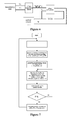
- Figure 1 is a block diagram showing the overall structure of the primary side of the system of the present invention.
- FIG. 2 is a block diagram showing control, driving and inverter parts of the present invention.
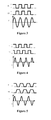
- Figure 3 is a diagram showing the standard alternating voltage waveform formed at both output ends of an inverter at the primary side.
- Figure 4 is a diagram showing the alternating voltage waveform caused by asynchronization of the hardware switches.
- Figure 5 is a diagram showing the delayed and tailed waveform of the control signal caused by the device.
- Figure 6 is a block diagram showing the coil frequency phase tracking and feedback part of the present invention.
- Figure 7 is a main flow chart of the control of the present invention.
- the wireless electrical power transmission system of the present invention includes a transmitting coil frequency generating part and a coil frequency phase tracking and feedback part.
- the transmitting coil frequency generating part includes a control circuit, a driving circuit and an inverter circuit, and the coil frequency phase tracking and feedback part includes a frequency detection circuit and a phase locked loop circuit.
- connection structure of the system is as follows.
- the control circuit refers to a Microprogrammed Control Unit (MCU) and its associated circuitry, and its output port is connected to the driving circuit; output ends of the driving circuit are respectively connected with control electrodes of a switching tube of the inverter circuit, thus constituting software-controlled frequency generating and controllable inverter circuits.
- the control circuit is controlled by software to output two opposite control signals, each of which controls the opening and closing of a switching tube after passing through the driving circuit, to alternatively generate voltages V1 and V2 for the transmitting coil, so that high-frequency oscillation is formed in the coil to enable energy transmission.
- control circuit may generate two signals P1 and P2, which are opposite under the control of software and more precise compared with that under the control of implementation purely by hardware LC circuits.
- standard alternating voltages can be formed at both ends of the transmitting coil.
- the coil frequency phase tracking and feedback part includes a frequency voltage sampling circuit and a phase locked loop circuit, and the signal output end of the phase locked loop circuit is connected to the control port of the control circuit.
- voltages V1 and V2 at both ends of the transmitting coil are sampled, and then compared by a voltage comparison circuit to obtain an oscillation frequency f in the transmitting coil. Specifically, if V1>V2, a voltage comparator in the voltage comparison circuit outputs a high level, and if V1 ⁇ V2, the voltage comparator outputs a low level, thereby obtaining the oscillation frequency f of the transmitting coil.
- a phase difference signal ⁇ may be generated during the comparison between the frequencies f and f0.
- the oscillation frequency f of the transmitting coil and the phase difference signal ⁇ are fed back to the control circuit, which then compares the frequency f0 with the fixed frequency point fk to obtain the size of the frequency drift, and then adjusts the frequency fp of the signals P1 and P2 according to the least square method or the median method.
- the frequency fp is compared and adjusted continuously in the system and eventually the frequency f is equal to the fixed frequency point fk, so that the system can be stabilized at the frequency point for energy transmission.
- the phase difference signal ⁇ may be used by the control circuit to finely tune and output the delay of outputting the signals P1 and P2.
- the phase locked loop is used to eliminate the drift phenomenon caused by a clock delay in a chip.
- the frequency signal is inputted to the phase locked loop to allow the consistency between the phase frequency of the frequency signal and that of a reference signal, so that the data drift phenomenon can be eliminated.
- the wireless electrical power transmission system with good thermal stability includes the transmitting coil frequency generating circuit and the coil frequency phase tracking and feedback circuit, where the transmitting coil frequency generating circuit includes the control circuit, the driving circuit and the inverter circuit, and the coil frequency phase tracking and feedback circuit includes the frequency detection circuit and the phase locked loop circuit.
- the control circuit is controlled by software to output two opposite control signals, each of which controls the opening and closing of a switching tube after passing through the driving circuit, to form the high-frequency oscillation in the transmitting coil.
- control circuit may generate two signals P1 and P2, which are opposite under the control of software and more precise compared with that under the control of implementation purely by hardware LC circuits.
- standard alternating voltages can be formed at both ends of the transmitting coil, as shown in Figure 3 .
- the inconsistency of parameters of the system device, and variation of the device parameter due to heat generation of the system may also cause the frequency drift.
- a phase tracking circuit may be used to solve the problem of the frequency drift.
- the switching tubes would be opened or closed simultaneously due to the asynchronization of hardware switches. If the switching tubes in the inverter circuit are opened at the same time, then a large current will be generated in the loop, thus the temperatures of the device and the coil will be increased, and the system will generate heat. The simultaneous opening or closing of the switching tubes will disable the oscillation of the transmitting coil, and therefore disable the energy transmission.
- the control signal may be delayed and tailed due to the difference of the device parameter or the influence of the environmental factor on the device parameter, resulting in the drift of the frequency point, as well as the phenomenon of the energy transmission interruption.
- a control method of the wireless electrical power transmission system of the present invention includes steps of:
- the inverter circuit is controlled precisely by software, so that the maximum active power and the minimum reactive power of the system are achieved. Therefore, the energy transmission efficiency of the system is improved while reducing the heat generation of system caused by the reactive power.
Landscapes
- Engineering & Computer Science (AREA)
- Computer Networks & Wireless Communication (AREA)
- Power Engineering (AREA)
- Physics & Mathematics (AREA)
- Electromagnetism (AREA)
- Inverter Devices (AREA)
Abstract
Description
- The present application relates to a wireless electrical power transmission system with good thermal stability and its control method.
- With the progress of science and technologies, wireless electrical power transmission technologies have been increasingly applied universally, which makes people's lives easier and more convenience, without the fetter of various power wires. Currently, some small-sized electronic devices may be charged in a wireless power supplying manner. For example, electronic devices such as a wireless charger, a wireless rechargeable mouse and a mobile phone may be automatically charged by a wireless power supplying device.
- For a wireless power supplying system of medium power (e.g. hundreds of watts), its primary side (i.e. the transmitting side) and tis secondary side (i.e. the receiving side) are operated in a deep coupled and synchronized state because of the large power, and a resonance circuit is typically employed as an output stage. Due to influence by factors such as component parameters and environment, a drift of a coil resonance frequency may be caused, which results in energy transmission in the system deflecting from the predetermined frequency point, thereby reducing the efficiency of the energy transmission; further, an energy loss may cause increased temperature of the coil and devices, and the resultant change of the parameter of the functional device, which varies with the environmental change, will be accumulated and cause the frequency drift, thereby forming a vicious cycle. As a result, a system failure may be caused, even the equipment might be destroyed.
- Currently, the solution for solving the above problems focuses on enabling the frequency stability. However, due to the inherent nature of physical properties of the devices per se, it is difficult to solve the problems fundamentally.
- An object of the present invention is to provide a wireless electrical power transmission system with good thermal stability and its control method, to achieve the stable temperature increase, improve the transmission efficiency of the system, and reduce the heat load of the system.
- In the technical solution of the present invention, the system is controlled by software, to eliminate the frequency point drift caused by the parameter of the device per se and the environmental temperature, precisely control the alternating current frequency characteristic and the frequency point of the wireless electrical power transmission circuit, solve the heat generation problem of the critical component, improve the power transmission efficiency of the wireless electrical power transmission circuit.
- In the method, the operating frequency of the primary coil is controlled and adjusted in real-time by software, so that the system is operated stably at the frequency point, the transmission of the active power is improved, and the generation of the reactive power is reduced, thereby enhancing the transmission efficiency of the wireless power supplying system, while eliminating the heat generation problem of the coil and the device. The method may be implemented by integrated circuits, so that the circuit design is simplified and the security and stability of the system is improved.
- The object of the present invention may be achieved as follows. The frequency of the transmitting coil is controlled by software, and the frequency drift caused by the parameter difference of the device per se is reduced as compared to the implementation of the hardware circuit; the frequency of the coil is tracked and adjusted in a real-time manner by software according to a real-time phase, to continuously approximate to the predetermined frequency point, so that the system can be operated stably at the frequency point, the system transmission efficiency is improved, and the heat generation problem is reduced; the opening and closing of a switching tube in an inverter circuit is controlled by software, thus a large current which is formed in the system loop due to the simultaneous opening of the switching tube is avoided, and the heat generation of the coil and devices is avoided; and the discontinuous energy transmission caused by the simultaneous opening or closing of the switching tube is also avoided.
- A control method of the wireless electrical power transmission system of the present invention includes steps of:
- providing control signals P1 and P2 with a frequency fp by a control circuit according to a frequency point fk, where fp = fk;
- opening or closing a switching tube by a driving circuit according to the control signals P1 and P2, so that an alternating voltage is formed at both ends of a transmitting coil, so that the high-frequency oscillation of the transmitting coil is started;
- obtaining a frequency f of the transmitting coil, after the voltage sampling by a voltage comparison circuit;
- processing the signal of the frequency f of the transmitting coil through a phase locked loop circuit, and feeding the processed signal back to the control circuit together with the phase difference signal;
- adjusting outputs of the control signals P1 and P2 by the control circuit according to the feedback signal; and
- repeating the above steps, so that the system is operated stably at the frequency point.
- The wireless electrical power transmission system of the present invention includes a transmitting coil frequency generating part and a coil frequency phase tracking and feedback part, where the transmitting coil frequency generating part includes a control circuit, a driving circuit and an inverter circuit, and the coil frequency phase tracking and feedback part includes a frequency detection circuit and a phase locked loop circuit.
- With respect to the transmitting coil frequency generating part, the control circuit is controlled by software to output two opposite control signals, each of which controls the opening and closing of a switching tube after passing through the driving circuit, to alternatively generate voltages V1 and V2 for the transmitting coil, so that high-frequency oscillation is formed in the coil to enable energy transmission. Depending on the resonance frequency, the control circuit may generate two signals P1 and P2, which are opposite under the control of software and more precise compared with that under the control of implementation purely by hardware LC circuits. Thus, standard alternating voltages can be formed at both ends of the transmitting coil.
- With respect to the coil frequency phase tracking and feedback part, voltages V1 and V2 at both ends of the transmitting coil are sampled, and then compared by a voltage comparison circuit to obtain an oscillation frequency f in the transmitting coil. Specifically, if V1>V2, a voltage comparator in the voltage comparison circuit outputs a high level, and if V1<V2, the voltage comparator outputs a low level, thereby obtaining the oscillation frequency f of the transmitting coil. A frequency f0 is obtained after the oscillation frequency f of the transmitting coil is processed by a phase comparator and a Voltage Controlled Oscillator (VCO). Eventually, f0 = f because of the effect of the phase locked loop. A phase difference signal ΔΦ may be generated during the comparison between the frequencies f and f0. The oscillation frequency f of the transmitting coil and the phase difference signal ΔΦ are fed back to the control circuit, which then compares the frequency f0 with the fixed frequency point fk to obtain the size of the frequency drift, and then adjusts the frequency fp of the signals P1 and P2 according to the least square method or the median method. The frequency fp is compared and adjusted continuously in the system and eventually the frequency f is equal to the fixed frequency point fk, so that the system can be stabilized at the frequency point for energy transmission. The phase difference signal ΔΦ may be used by the control circuit to finely tune and output the delay of outputting the signals P1 and P2.
- The phase locked loop is used to eliminate the drift phenomenon caused by a clock delay in a chip. The frequency signal is inputted to the phase locked loop to allow the consistency between the phase frequency of the frequency signal and that of a reference signal, so that the data drift phenomenon can be eliminated.
- As described above, the wireless electrical power transmission system with good thermal stability includes the transmitting coil frequency generating circuit and the coil frequency phase tracking and feedback circuit, where the transmitting coil frequency generating circuit includes the control circuit, the driving circuit and the inverter circuit, and the coil frequency phase tracking and feedback circuit includes the frequency detection circuit and the phase locked loop circuit.
- It is characterized in that the control circuit is controlled by software to output two opposite control signals, each of which controls the opening and closing of a switching tube after passing through the driving circuit, to alternatively generate voltages V1 and V2 for the transmitting coil and form high-frequency oscillation in the coil.
- Depending on the resonance frequency, the control circuit may generate two signals P1 and P2, which are opposite under the control of software and more precise compared with that under the control of implementation purely by hardware LC circuits. Thus, standard alternating voltages can be formed at both ends of the transmitting coil.
- The inconsistency of parameters of the system device, and variation of the device parameter due to heat generation of the system, may also cause the frequency drift. In this case, a phase tracking circuit may be used to solve the problem of the frequency drift.
- The switching tubes would be opened or closed simultaneously due to the asynchronization of hardware switches. If the switching tubes in the inverter circuit are opened at the same time, then a large current will be generated in the loop, thus the temperatures of the device and the coil will be increased, and the system will generate heat. The simultaneous opening or closing of the switching tubes will disable the oscillation of the transmitting coil, and therefore disable the energy transmission.
- The control signal may be delayed and tailed due to the difference of the device parameter or the influence of the environmental factor on the device parameter, resulting in the drift of the frequency point, as well as the phenomenon of the energy transmission interruption.
- The inverter circuit is controlled precisely by software, so that the maximum active power and the minimum reactive power of the system are achieved. Therefore, the energy transmission efficiency of the system is improved while reducing the heat generation of system caused by the reactive power.
- The advantage of the invention lies in that: the frequency of the transmitting coil is controlled by software, and the frequency drift caused by the parameter difference of the device per se is reduced as compared to the implementation of the hardware circuit.
- The frequency of the coil is tracked and adjusted in a real-time manner by software according to a real-time phase, to continuously approximate to the predetermined frequency point, so that the system can be operated stably at the frequency point, the system transmission efficiency is improved, and the heat generation problem is reduced.
- The precise control of the frequency point of the wireless electrical power transmission circuit, including the control of frequency and timing, are achieved by a Complex Programmable Logic Device (CPLD).
- The opening and closing of a switching tube in an inverter circuit is controlled by software, thus a large current which is formed in the system loop due to the simultaneous opening of the switching tube is avoided, and the heat generation of the coil and devices is avoided; and the discontinuous energy transmission caused by the simultaneous opening or closing of the switching tube is also avoided.
- 1. Through the control by software, the frequency drift caused by parameter of the device per se and the environmental temperature is reduced, to achieve the precise control of the frequency point of the frequency wireless electrical power transmission circuit and alternating current frequency characteristics.
- 2. By the software-controlled method, the frequency of the coil can be quickly moved to the predetermined frequency point, for the purpose of stable operation.
- 3. The heat generation problem of key devices can be eliminated, to reduce the reactive power of the entire system, extend the circuit life, and improve the transmission efficiency of the wireless electrical power transmission circuit.
-
Figure 1 is a block diagram showing the overall structure of the primary side of the system of the present invention. -
Figure 2 is a block diagram showing control, driving and inverter parts of the present invention. -
Figure 3 is a diagram showing the standard alternating voltage waveform formed at both output ends of an inverter at the primary side. -
Figure 4 is a diagram showing the alternating voltage waveform caused by asynchronization of the hardware switches. -
Figure 5 is a diagram showing the delayed and tailed waveform of the control signal caused by the device. -
Figure 6 is a block diagram showing the coil frequency phase tracking and feedback part of the present invention. -
Figure 7 is a main flow chart of the control of the present invention. - The wireless electrical power transmission system of the present invention includes a transmitting coil frequency generating part and a coil frequency phase tracking and feedback part. The transmitting coil frequency generating part includes a control circuit, a driving circuit and an inverter circuit, and the coil frequency phase tracking and feedback part includes a frequency detection circuit and a phase locked loop circuit.
- The specific connection structure of the system is as follows.
- Referring to
Figure 1 , with respect to the transmitting coil frequency generating part, the control circuit refers to a Microprogrammed Control Unit (MCU) and its associated circuitry, and its output port is connected to the driving circuit; output ends of the driving circuit are respectively connected with control electrodes of a switching tube of the inverter circuit, thus constituting software-controlled frequency generating and controllable inverter circuits. The control circuit is controlled by software to output two opposite control signals, each of which controls the opening and closing of a switching tube after passing through the driving circuit, to alternatively generate voltages V1 and V2 for the transmitting coil, so that high-frequency oscillation is formed in the coil to enable energy transmission. Depending on the resonance frequency, the control circuit may generate two signals P1 and P2, which are opposite under the control of software and more precise compared with that under the control of implementation purely by hardware LC circuits. Thus, standard alternating voltages can be formed at both ends of the transmitting coil. - Referring to
Figures 2 and6 , the coil frequency phase tracking and feedback part includes a frequency voltage sampling circuit and a phase locked loop circuit, and the signal output end of the phase locked loop circuit is connected to the control port of the control circuit. - With respect to the coil frequency phase tracking and feedback part, voltages V1 and V2 at both ends of the transmitting coil are sampled, and then compared by a voltage comparison circuit to obtain an oscillation frequency f in the transmitting coil. Specifically, if V1>V2, a voltage comparator in the voltage comparison circuit outputs a high level, and if V1<V2, the voltage comparator outputs a low level, thereby obtaining the oscillation frequency f of the transmitting coil. A frequency f0 is obtained after the oscillation frequency f of the transmitting coil is processed by a phase comparator and a Voltage Controlled Oscillator (VCO). Eventually, f0 = f because of the effect of the phase locked loop. A phase difference signal ΔΦ may be generated during the comparison between the frequencies f and f0. The oscillation frequency f of the transmitting coil and the phase difference signal ΔΦ are fed back to the control circuit, which then compares the frequency f0 with the fixed frequency point fk to obtain the size of the frequency drift, and then adjusts the frequency fp of the signals P1 and P2 according to the least square method or the median method. The frequency fp is compared and adjusted continuously in the system and eventually the frequency f is equal to the fixed frequency point fk, so that the system can be stabilized at the frequency point for energy transmission. The phase difference signal ΔΦ may be used by the control circuit to finely tune and output the delay of outputting the signals P1 and P2.
- The phase locked loop is used to eliminate the drift phenomenon caused by a clock delay in a chip. The frequency signal is inputted to the phase locked loop to allow the consistency between the phase frequency of the frequency signal and that of a reference signal, so that the data drift phenomenon can be eliminated.
- As described above, the wireless electrical power transmission system with good thermal stability includes the transmitting coil frequency generating circuit and the coil frequency phase tracking and feedback circuit, where the transmitting coil frequency generating circuit includes the control circuit, the driving circuit and the inverter circuit, and the coil frequency phase tracking and feedback circuit includes the frequency detection circuit and the phase locked loop circuit. The control circuit is controlled by software to output two opposite control signals, each of which controls the opening and closing of a switching tube after passing through the driving circuit, to form the high-frequency oscillation in the transmitting coil.
- Depending on the resonance frequency, the control circuit may generate two signals P1 and P2, which are opposite under the control of software and more precise compared with that under the control of implementation purely by hardware LC circuits. Thus, standard alternating voltages can be formed at both ends of the transmitting coil, as shown in
Figure 3 . - Referring to
Figure 5 , the inconsistency of parameters of the system device, and variation of the device parameter due to heat generation of the system, may also cause the frequency drift. In this case, a phase tracking circuit may be used to solve the problem of the frequency drift. - Referring to
Figure 4 , the switching tubes would be opened or closed simultaneously due to the asynchronization of hardware switches. If the switching tubes in the inverter circuit are opened at the same time, then a large current will be generated in the loop, thus the temperatures of the device and the coil will be increased, and the system will generate heat. The simultaneous opening or closing of the switching tubes will disable the oscillation of the transmitting coil, and therefore disable the energy transmission. - The control signal may be delayed and tailed due to the difference of the device parameter or the influence of the environmental factor on the device parameter, resulting in the drift of the frequency point, as well as the phenomenon of the energy transmission interruption.
- Referring to
Figure 7 , a control method of the wireless electrical power transmission system of the present invention includes steps of: - providing control signals P1 and P2 with a frequency fp by a control circuit according to a frequency point fk, where fp = fk;
- opening or closing a switching tube by a driving circuit according to the control signals P1 and P2, so that an alternating voltage is formed at both ends of a transmitting coil, so that the high-frequency oscillation of the transmitting coil is started;
- obtaining a frequency f of the transmitting coil, after the voltage sampling by a voltage comparison circuit;
- processing the signal of the frequency f of the transmitting coil through a phase locked loop circuit, and feeding the processed signal back to the control circuit together with the phase difference signal;
- adjusting outputs of the control signals P1 and P2 by the control circuit according to the feedback signal; and
- repeating the above steps, so that the system is operated stably at the frequency point.
- The inverter circuit is controlled precisely by software, so that the maximum active power and the minimum reactive power of the system are achieved. Therefore, the energy transmission efficiency of the system is improved while reducing the heat generation of system caused by the reactive power.
- The above description merely relates to the preferred embodiments of the present invention, and is not intended to limit the present invention in any case. Although the present invention has been disclosed with the above preferred embodiment, the embodiment is not intended to limit the present invention. Those skilled in the art can amend and modify the above disclosed technical contents as equivalent embodiments, without departing from the scope of the technical solution of the present invention. However, the contents without departing from the technical solution of the present invention, any amendments, equivalent variations and modifications of the above embodiments based on the technical essence of the present invention, should fall into the scope of the technical solution of the present invention.
Claims (4)
- A wireless electrical power transmission system, comprising a transmitting coil frequency generating circuit and a coil frequency phase tracking and feedback circuit, wherein the transmitting coil frequency generating circuit includes a control circuit, a driving circuit and an inverter circuit, characterized in that:the control circuit is controlled by software to output two opposite control signals, each of which controls the opening and closing of a switching tube after passing through the driving circuit, to form high-frequency oscillation in the transmitting coil.
- The system of claim 1, wherein the control circuit of the transmitting coil frequency generating circuit includes a Microprogrammed Control Unit, and an output port of the control circuit is connected to the driving circuit, output ends of the driving circuit are respectively connected with control electrodes of a switching tube of the inverter circuit, constituting software-controlled frequency generation and controllable inverter circuits.
- The system of claim 1, wherein the coil frequency phase tracking and feedback circuit includes a frequency voltage sampling circuit and a phase locked loop circuit, and a signal output end of the phase locked loop circuit is connected to a control port of the control circuit.
- A control method of a wireless electrical power transmission system, characterized by comprising steps of:providing control signals P1 and P2 with a frequency fp by a control circuit according to a frequency point fk, wherein fp = fk;opening or closing a switching tube by a driving circuit according to the control signals P1 and P2, so that an alternating voltage is formed at both ends of a transmitting coil, so that high-frequency oscillation of the transmitting coil is started;obtaining a frequency f of the transmitting coil, after the voltage sampling by a voltage comparison circuit;processing the signal of the frequency f of the transmitting coil through a phase locked loop circuit, and feeding the processed signal back to the control circuit together with a phase difference signal;adjusting outputs of the control signals P1 and P2 by the control circuit according to the feedback signal; andrepeating the above steps, so that the system is operated stably at the frequency point.
Priority Applications (1)
| Application Number | Priority Date | Filing Date | Title |
|---|---|---|---|
| PT11856967T PT2639932T (en) | 2011-01-30 | 2011-01-30 | Wireless electrical power transmission system and its control method |
Applications Claiming Priority (1)
| Application Number | Priority Date | Filing Date | Title |
|---|---|---|---|
| PCT/CN2011/070814 WO2012100435A1 (en) | 2011-01-30 | 2011-01-30 | Wireless electrical power transmission system and its control method |
Publications (3)
| Publication Number | Publication Date |
|---|---|
| EP2639932A1 true EP2639932A1 (en) | 2013-09-18 |
| EP2639932A4 EP2639932A4 (en) | 2016-11-16 |
| EP2639932B1 EP2639932B1 (en) | 2018-10-10 |
Family
ID=46580209
Family Applications (1)
| Application Number | Title | Priority Date | Filing Date |
|---|---|---|---|
| EP11856967.2A Active EP2639932B1 (en) | 2011-01-30 | 2011-01-30 | Wireless electrical power transmission system and its control method |
Country Status (6)
| Country | Link |
|---|---|
| US (1) | US20130300203A1 (en) |
| EP (1) | EP2639932B1 (en) |
| JP (1) | JP5650336B2 (en) |
| CN (1) | CN103688441B (en) |
| PT (1) | PT2639932T (en) |
| WO (1) | WO2012100435A1 (en) |
Families Citing this family (4)
| Publication number | Priority date | Publication date | Assignee | Title |
|---|---|---|---|---|
| KR102312096B1 (en) * | 2015-02-06 | 2021-10-13 | 엘지전자 주식회사 | Wireless power transfer method, apparatus and system |
| CN104716752B (en) * | 2015-04-12 | 2017-11-17 | 湖南大学 | A kind of induction electric energy transmission control unit and its control method |
| CN107171452B (en) * | 2017-04-21 | 2020-02-07 | 西安电子科技大学 | Pi-type impedance automatic matching system and method in radio frequency energy acquisition circuit |
| CN115051480B (en) * | 2022-05-26 | 2025-01-10 | 中国人民解放军海军工程大学 | Array coupler control structure and control method for array wireless power transmission system |
Family Cites Families (12)
| Publication number | Priority date | Publication date | Assignee | Title |
|---|---|---|---|---|
| US5450305A (en) * | 1991-08-12 | 1995-09-12 | Auckland Uniservices Limited | Resonant power supplies |
| JPH1092673A (en) * | 1996-07-26 | 1998-04-10 | Tdk Corp | Non-contact power transmission equipment |
| JP2004248365A (en) * | 2003-02-12 | 2004-09-02 | Yazaki Corp | Contactless power transmission device, contactless power transmission method |
| US7187226B2 (en) * | 2004-07-01 | 2007-03-06 | Analog Devices, Inc. | Anti-cross conduction drive control circuit and method |
| US7208912B2 (en) * | 2004-09-24 | 2007-04-24 | Lear Corporation | Inductive battery recharging system with peak voltage detection |
| JP2006230028A (en) * | 2005-02-15 | 2006-08-31 | Meidensha Corp | Method of compensating current of active filter |
| CN1996711A (en) * | 2006-12-08 | 2007-07-11 | 广州电器科学研究院 | Inductive coupled wireless power transfer device |
| JP4308858B2 (en) * | 2007-02-16 | 2009-08-05 | セイコーエプソン株式会社 | Power transmission control device, power reception control device, non-contact power transmission system, power transmission device, power reception device, and electronic equipment |
| US8947041B2 (en) * | 2008-09-02 | 2015-02-03 | Qualcomm Incorporated | Bidirectional wireless power transmission |
| JP4620151B2 (en) * | 2008-12-12 | 2011-01-26 | 東光株式会社 | Non-contact power transmission circuit |
| JP4893755B2 (en) * | 2009-01-14 | 2012-03-07 | セイコーエプソン株式会社 | Power transmission control device, power transmission device, electronic device, and load state detection circuit |
| JP5369693B2 (en) * | 2009-01-15 | 2013-12-18 | 日産自動車株式会社 | Non-contact power feeding device |
-
2011
- 2011-01-30 JP JP2013550731A patent/JP5650336B2/en not_active Expired - Fee Related
- 2011-01-30 PT PT11856967T patent/PT2639932T/en unknown
- 2011-01-30 US US13/821,563 patent/US20130300203A1/en not_active Abandoned
- 2011-01-30 WO PCT/CN2011/070814 patent/WO2012100435A1/en not_active Ceased
- 2011-01-30 EP EP11856967.2A patent/EP2639932B1/en active Active
- 2011-01-30 CN CN201180009163.0A patent/CN103688441B/en not_active Expired - Fee Related
Also Published As
| Publication number | Publication date |
|---|---|
| EP2639932B1 (en) | 2018-10-10 |
| WO2012100435A1 (en) | 2012-08-02 |
| CN103688441A (en) | 2014-03-26 |
| PT2639932T (en) | 2019-01-17 |
| US20130300203A1 (en) | 2013-11-14 |
| JP2014506774A (en) | 2014-03-17 |
| JP5650336B2 (en) | 2015-01-07 |
| EP2639932A4 (en) | 2016-11-16 |
| CN103688441B (en) | 2017-03-22 |
Similar Documents
| Publication | Publication Date | Title |
|---|---|---|
| US9991748B2 (en) | Wireless power transmission system and power transmission device | |
| Tahir et al. | Frequency and phase modulation performance of an injection-locked CW magnetron | |
| CN104393623B (en) | A kind of frequency locking method and system for magnetic resonance wireless charging system | |
| CN106160414A (en) | The synchronization of pulsewidth modulation switching frequency has the switching power converter of improvement | |
| US10404258B2 (en) | Integrated circuit device having an injection-locked oscillator | |
| TW201737609A (en) | Dynamic system resonant frequency detection and compensation methods for WPT and relevant technologies | |
| EP2639932B1 (en) | Wireless electrical power transmission system and its control method | |
| CN104716827A (en) | DC-DC voltage converter and conversion method | |
| CN104811055A (en) | High power wideband ultrasonic power supply based on silicon carbide device and control method thereof | |
| Cochran et al. | Discrete time synchronization modeling for active rectifiers in wireless power transfer systems | |
| US20200328620A1 (en) | Tuner and rectifier circuit for wireless power receiver | |
| KR20220119178A (en) | Load abnormality detecting circuit for inverter | |
| Pucci et al. | Synchronous operation of high-frequency inductive power transfer systems through injection locking | |
| CN101951179B (en) | Synchronous rectification circuit and synchronous rectification method | |
| CN113615034A (en) | Series distributed radio frequency generator for wireless power transfer | |
| US9160352B1 (en) | Phase-locked loop and method for controlling the same | |
| US20190260359A1 (en) | Tuner and rectifier apparatus for wireless power transfer receiver | |
| RU2662228C1 (en) | Method of frequency-pulse regulation of resonant converter with phase auto-tuning of pulse width | |
| CN207082912U (en) | A kind of magnetic induction mobile phone wireless charging emitter | |
| CN115102542B (en) | Phase-locked loop frequency fast switching circuit, phase-locked loop and control method | |
| Hao et al. | Clock Pulling Enables Maximum-Efficiency Wireless Power Transfer | |
| Lijuan et al. | The design of frequency tracking control circuit in induction heating power supply based on SG3525 | |
| US7449962B2 (en) | Phase-controlled current source for phase-locked loop | |
| CN118041082A (en) | LLC resonant converter and control method and control device thereof | |
| CN109149786A (en) | A kind of magnetic induction mobile phone wireless charging emitter |
Legal Events
| Date | Code | Title | Description |
|---|---|---|---|
| PUAI | Public reference made under article 153(3) epc to a published international application that has entered the european phase |
Free format text: ORIGINAL CODE: 0009012 |
|
| 17P | Request for examination filed |
Effective date: 20130612 |
|
| AK | Designated contracting states |
Kind code of ref document: A1 Designated state(s): AL AT BE BG CH CY CZ DE DK EE ES FI FR GB GR HR HU IE IS IT LI LT LU LV MC MK MT NL NO PL PT RO RS SE SI SK SM TR |
|
| DAX | Request for extension of the european patent (deleted) | ||
| REG | Reference to a national code |
Ref country code: DE Ref legal event code: R079 Ref document number: 602011052872 Country of ref document: DE Free format text: PREVIOUS MAIN CLASS: H02J0017000000 Ipc: H02J0005000000 |
|
| RA4 | Supplementary search report drawn up and despatched (corrected) |
Effective date: 20161018 |
|
| RIC1 | Information provided on ipc code assigned before grant |
Ipc: H02J 5/00 20160101AFI20161012BHEP |
|
| STAA | Information on the status of an ep patent application or granted ep patent |
Free format text: STATUS: EXAMINATION IS IN PROGRESS |
|
| 17Q | First examination report despatched |
Effective date: 20170908 |
|
| GRAP | Despatch of communication of intention to grant a patent |
Free format text: ORIGINAL CODE: EPIDOSNIGR1 |
|
| STAA | Information on the status of an ep patent application or granted ep patent |
Free format text: STATUS: GRANT OF PATENT IS INTENDED |
|
| INTG | Intention to grant announced |
Effective date: 20180503 |
|
| GRAS | Grant fee paid |
Free format text: ORIGINAL CODE: EPIDOSNIGR3 |
|
| GRAA | (expected) grant |
Free format text: ORIGINAL CODE: 0009210 |
|
| STAA | Information on the status of an ep patent application or granted ep patent |
Free format text: STATUS: THE PATENT HAS BEEN GRANTED |
|
| AK | Designated contracting states |
Kind code of ref document: B1 Designated state(s): AL AT BE BG CH CY CZ DE DK EE ES FI FR GB GR HR HU IE IS IT LI LT LU LV MC MK MT NL NO PL PT RO RS SE SI SK SM TR |
|
| REG | Reference to a national code |
Ref country code: GB Ref legal event code: FG4D |
|
| REG | Reference to a national code |
Ref country code: CH Ref legal event code: EP Ref country code: AT Ref legal event code: REF Ref document number: 1052361 Country of ref document: AT Kind code of ref document: T Effective date: 20181015 |
|
| REG | Reference to a national code |
Ref country code: IE Ref legal event code: FG4D |
|
| REG | Reference to a national code |
Ref country code: DE Ref legal event code: R096 Ref document number: 602011052872 Country of ref document: DE |
|
| REG | Reference to a national code |
Ref country code: PT Ref legal event code: SC4A Ref document number: 2639932 Country of ref document: PT Date of ref document: 20190117 Kind code of ref document: T Free format text: AVAILABILITY OF NATIONAL TRANSLATION Effective date: 20190104 |
|
| REG | Reference to a national code |
Ref country code: SE Ref legal event code: TRGR |
|
| REG | Reference to a national code |
Ref country code: NL Ref legal event code: FP |
|
| REG | Reference to a national code |
Ref country code: LT Ref legal event code: MG4D |
|
| REG | Reference to a national code |
Ref country code: AT Ref legal event code: MK05 Ref document number: 1052361 Country of ref document: AT Kind code of ref document: T Effective date: 20181010 |
|
| PG25 | Lapsed in a contracting state [announced via postgrant information from national office to epo] |
Ref country code: BG Free format text: LAPSE BECAUSE OF FAILURE TO SUBMIT A TRANSLATION OF THE DESCRIPTION OR TO PAY THE FEE WITHIN THE PRESCRIBED TIME-LIMIT Effective date: 20190110 Ref country code: AT Free format text: LAPSE BECAUSE OF FAILURE TO SUBMIT A TRANSLATION OF THE DESCRIPTION OR TO PAY THE FEE WITHIN THE PRESCRIBED TIME-LIMIT Effective date: 20181010 Ref country code: PL Free format text: LAPSE BECAUSE OF FAILURE TO SUBMIT A TRANSLATION OF THE DESCRIPTION OR TO PAY THE FEE WITHIN THE PRESCRIBED TIME-LIMIT Effective date: 20181010 Ref country code: HR Free format text: LAPSE BECAUSE OF FAILURE TO SUBMIT A TRANSLATION OF THE DESCRIPTION OR TO PAY THE FEE WITHIN THE PRESCRIBED TIME-LIMIT Effective date: 20181010 Ref country code: ES Free format text: LAPSE BECAUSE OF FAILURE TO SUBMIT A TRANSLATION OF THE DESCRIPTION OR TO PAY THE FEE WITHIN THE PRESCRIBED TIME-LIMIT Effective date: 20181010 Ref country code: IS Free format text: LAPSE BECAUSE OF FAILURE TO SUBMIT A TRANSLATION OF THE DESCRIPTION OR TO PAY THE FEE WITHIN THE PRESCRIBED TIME-LIMIT Effective date: 20190210 Ref country code: NO Free format text: LAPSE BECAUSE OF FAILURE TO SUBMIT A TRANSLATION OF THE DESCRIPTION OR TO PAY THE FEE WITHIN THE PRESCRIBED TIME-LIMIT Effective date: 20190110 Ref country code: LT Free format text: LAPSE BECAUSE OF FAILURE TO SUBMIT A TRANSLATION OF THE DESCRIPTION OR TO PAY THE FEE WITHIN THE PRESCRIBED TIME-LIMIT Effective date: 20181010 Ref country code: FI Free format text: LAPSE BECAUSE OF FAILURE TO SUBMIT A TRANSLATION OF THE DESCRIPTION OR TO PAY THE FEE WITHIN THE PRESCRIBED TIME-LIMIT Effective date: 20181010 Ref country code: LV Free format text: LAPSE BECAUSE OF FAILURE TO SUBMIT A TRANSLATION OF THE DESCRIPTION OR TO PAY THE FEE WITHIN THE PRESCRIBED TIME-LIMIT Effective date: 20181010 |
|
| PG25 | Lapsed in a contracting state [announced via postgrant information from national office to epo] |
Ref country code: GR Free format text: LAPSE BECAUSE OF FAILURE TO SUBMIT A TRANSLATION OF THE DESCRIPTION OR TO PAY THE FEE WITHIN THE PRESCRIBED TIME-LIMIT Effective date: 20190111 Ref country code: RS Free format text: LAPSE BECAUSE OF FAILURE TO SUBMIT A TRANSLATION OF THE DESCRIPTION OR TO PAY THE FEE WITHIN THE PRESCRIBED TIME-LIMIT Effective date: 20181010 Ref country code: AL Free format text: LAPSE BECAUSE OF FAILURE TO SUBMIT A TRANSLATION OF THE DESCRIPTION OR TO PAY THE FEE WITHIN THE PRESCRIBED TIME-LIMIT Effective date: 20181010 |
|
| REG | Reference to a national code |
Ref country code: DE Ref legal event code: R097 Ref document number: 602011052872 Country of ref document: DE |
|
| PG25 | Lapsed in a contracting state [announced via postgrant information from national office to epo] |
Ref country code: DK Free format text: LAPSE BECAUSE OF FAILURE TO SUBMIT A TRANSLATION OF THE DESCRIPTION OR TO PAY THE FEE WITHIN THE PRESCRIBED TIME-LIMIT Effective date: 20181010 Ref country code: CZ Free format text: LAPSE BECAUSE OF FAILURE TO SUBMIT A TRANSLATION OF THE DESCRIPTION OR TO PAY THE FEE WITHIN THE PRESCRIBED TIME-LIMIT Effective date: 20181010 |
|
| PLBE | No opposition filed within time limit |
Free format text: ORIGINAL CODE: 0009261 |
|
| STAA | Information on the status of an ep patent application or granted ep patent |
Free format text: STATUS: NO OPPOSITION FILED WITHIN TIME LIMIT |
|
| PG25 | Lapsed in a contracting state [announced via postgrant information from national office to epo] |
Ref country code: MC Free format text: LAPSE BECAUSE OF FAILURE TO SUBMIT A TRANSLATION OF THE DESCRIPTION OR TO PAY THE FEE WITHIN THE PRESCRIBED TIME-LIMIT Effective date: 20181010 Ref country code: RO Free format text: LAPSE BECAUSE OF FAILURE TO SUBMIT A TRANSLATION OF THE DESCRIPTION OR TO PAY THE FEE WITHIN THE PRESCRIBED TIME-LIMIT Effective date: 20181010 Ref country code: EE Free format text: LAPSE BECAUSE OF FAILURE TO SUBMIT A TRANSLATION OF THE DESCRIPTION OR TO PAY THE FEE WITHIN THE PRESCRIBED TIME-LIMIT Effective date: 20181010 Ref country code: SM Free format text: LAPSE BECAUSE OF FAILURE TO SUBMIT A TRANSLATION OF THE DESCRIPTION OR TO PAY THE FEE WITHIN THE PRESCRIBED TIME-LIMIT Effective date: 20181010 Ref country code: SK Free format text: LAPSE BECAUSE OF FAILURE TO SUBMIT A TRANSLATION OF THE DESCRIPTION OR TO PAY THE FEE WITHIN THE PRESCRIBED TIME-LIMIT Effective date: 20181010 |
|
| REG | Reference to a national code |
Ref country code: CH Ref legal event code: PL |
|
| 26N | No opposition filed |
Effective date: 20190711 |
|
| PG25 | Lapsed in a contracting state [announced via postgrant information from national office to epo] |
Ref country code: LU Free format text: LAPSE BECAUSE OF NON-PAYMENT OF DUE FEES Effective date: 20190130 |
|
| REG | Reference to a national code |
Ref country code: BE Ref legal event code: MM Effective date: 20190131 |
|
| REG | Reference to a national code |
Ref country code: IE Ref legal event code: MM4A |
|
| PG25 | Lapsed in a contracting state [announced via postgrant information from national office to epo] |
Ref country code: SI Free format text: LAPSE BECAUSE OF FAILURE TO SUBMIT A TRANSLATION OF THE DESCRIPTION OR TO PAY THE FEE WITHIN THE PRESCRIBED TIME-LIMIT Effective date: 20181010 |
|
| PG25 | Lapsed in a contracting state [announced via postgrant information from national office to epo] |
Ref country code: BE Free format text: LAPSE BECAUSE OF NON-PAYMENT OF DUE FEES Effective date: 20190131 |
|
| PG25 | Lapsed in a contracting state [announced via postgrant information from national office to epo] |
Ref country code: CH Free format text: LAPSE BECAUSE OF NON-PAYMENT OF DUE FEES Effective date: 20190131 Ref country code: LI Free format text: LAPSE BECAUSE OF NON-PAYMENT OF DUE FEES Effective date: 20190131 |
|
| PG25 | Lapsed in a contracting state [announced via postgrant information from national office to epo] |
Ref country code: IE Free format text: LAPSE BECAUSE OF NON-PAYMENT OF DUE FEES Effective date: 20190130 |
|
| PG25 | Lapsed in a contracting state [announced via postgrant information from national office to epo] |
Ref country code: MT Free format text: LAPSE BECAUSE OF NON-PAYMENT OF DUE FEES Effective date: 20190130 |
|
| PG25 | Lapsed in a contracting state [announced via postgrant information from national office to epo] |
Ref country code: CY Free format text: LAPSE BECAUSE OF FAILURE TO SUBMIT A TRANSLATION OF THE DESCRIPTION OR TO PAY THE FEE WITHIN THE PRESCRIBED TIME-LIMIT Effective date: 20181010 |
|
| PG25 | Lapsed in a contracting state [announced via postgrant information from national office to epo] |
Ref country code: HU Free format text: LAPSE BECAUSE OF FAILURE TO SUBMIT A TRANSLATION OF THE DESCRIPTION OR TO PAY THE FEE WITHIN THE PRESCRIBED TIME-LIMIT; INVALID AB INITIO Effective date: 20110130 |
|
| PG25 | Lapsed in a contracting state [announced via postgrant information from national office to epo] |
Ref country code: MK Free format text: LAPSE BECAUSE OF FAILURE TO SUBMIT A TRANSLATION OF THE DESCRIPTION OR TO PAY THE FEE WITHIN THE PRESCRIBED TIME-LIMIT Effective date: 20181010 |
|
| PGFP | Annual fee paid to national office [announced via postgrant information from national office to epo] |
Ref country code: NL Payment date: 20241224 Year of fee payment: 15 Ref country code: PT Payment date: 20241218 Year of fee payment: 15 |
|
| PGFP | Annual fee paid to national office [announced via postgrant information from national office to epo] |
Ref country code: SE Payment date: 20250128 Year of fee payment: 15 |
|
| PGFP | Annual fee paid to national office [announced via postgrant information from national office to epo] |
Ref country code: FR Payment date: 20250130 Year of fee payment: 15 |
|
| PGFP | Annual fee paid to national office [announced via postgrant information from national office to epo] |
Ref country code: IT Payment date: 20250109 Year of fee payment: 15 |
|
| PGFP | Annual fee paid to national office [announced via postgrant information from national office to epo] |
Ref country code: TR Payment date: 20250124 Year of fee payment: 15 |
|
| REG | Reference to a national code |
Ref country code: DE Ref legal event code: R079 Ref document number: 602011052872 Country of ref document: DE Free format text: PREVIOUS MAIN CLASS: H02J0005000000 Ipc: H02J0004250000 |
|
| PGFP | Annual fee paid to national office [announced via postgrant information from national office to epo] |
Ref country code: GB Payment date: 20260127 Year of fee payment: 16 |
|
| PGFP | Annual fee paid to national office [announced via postgrant information from national office to epo] |
Ref country code: DE Payment date: 20260114 Year of fee payment: 16 |