EP2639898A1 - A method for controlling signal gain of a raman amplifier - Google Patents
A method for controlling signal gain of a raman amplifier Download PDFInfo
- Publication number
- EP2639898A1 EP2639898A1 EP13151972.0A EP13151972A EP2639898A1 EP 2639898 A1 EP2639898 A1 EP 2639898A1 EP 13151972 A EP13151972 A EP 13151972A EP 2639898 A1 EP2639898 A1 EP 2639898A1
- Authority
- EP
- European Patent Office
- Prior art keywords
- signal
- optical
- pump
- raman amplifier
- gain
- Prior art date
- Legal status (The legal status is an assumption and is not a legal conclusion. Google has not performed a legal analysis and makes no representation as to the accuracy of the status listed.)
- Granted
Links
Images


Classifications
-
- H—ELECTRICITY
- H01—ELECTRIC ELEMENTS
- H01S—DEVICES USING THE PROCESS OF LIGHT AMPLIFICATION BY STIMULATED EMISSION OF RADIATION [LASER] TO AMPLIFY OR GENERATE LIGHT; DEVICES USING STIMULATED EMISSION OF ELECTROMAGNETIC RADIATION IN WAVE RANGES OTHER THAN OPTICAL
- H01S3/00—Lasers, i.e. devices using stimulated emission of electromagnetic radiation in the infrared, visible or ultraviolet wave range
- H01S3/10—Controlling the intensity, frequency, phase, polarisation or direction of the emitted radiation, e.g. switching, gating, modulating or demodulating
- H01S3/13—Stabilisation of laser output parameters, e.g. frequency or amplitude
- H01S3/1301—Stabilisation of laser output parameters, e.g. frequency or amplitude in optical amplifiers
- H01S3/1302—Stabilisation of laser output parameters, e.g. frequency or amplitude in optical amplifiers by all-optical means, e.g. gain-clamping
-
- H—ELECTRICITY
- H01—ELECTRIC ELEMENTS
- H01S—DEVICES USING THE PROCESS OF LIGHT AMPLIFICATION BY STIMULATED EMISSION OF RADIATION [LASER] TO AMPLIFY OR GENERATE LIGHT; DEVICES USING STIMULATED EMISSION OF ELECTROMAGNETIC RADIATION IN WAVE RANGES OTHER THAN OPTICAL
- H01S3/00—Lasers, i.e. devices using stimulated emission of electromagnetic radiation in the infrared, visible or ultraviolet wave range
- H01S3/05—Construction or shape of optical resonators; Accommodation of active medium therein; Shape of active medium
- H01S3/06—Construction or shape of active medium
- H01S3/063—Waveguide lasers, i.e. whereby the dimensions of the waveguide are of the order of the light wavelength
- H01S3/067—Fibre lasers
- H01S3/06754—Fibre amplifiers
-
- H—ELECTRICITY
- H01—ELECTRIC ELEMENTS
- H01S—DEVICES USING THE PROCESS OF LIGHT AMPLIFICATION BY STIMULATED EMISSION OF RADIATION [LASER] TO AMPLIFY OR GENERATE LIGHT; DEVICES USING STIMULATED EMISSION OF ELECTROMAGNETIC RADIATION IN WAVE RANGES OTHER THAN OPTICAL
- H01S3/00—Lasers, i.e. devices using stimulated emission of electromagnetic radiation in the infrared, visible or ultraviolet wave range
- H01S3/09—Processes or apparatus for excitation, e.g. pumping
- H01S3/091—Processes or apparatus for excitation, e.g. pumping using optical pumping
- H01S3/094—Processes or apparatus for excitation, e.g. pumping using optical pumping by coherent light
- H01S3/094042—Processes or apparatus for excitation, e.g. pumping using optical pumping by coherent light of a fibre laser
- H01S3/094046—Processes or apparatus for excitation, e.g. pumping using optical pumping by coherent light of a fibre laser of a Raman fibre laser
-
- H—ELECTRICITY
- H01—ELECTRIC ELEMENTS
- H01S—DEVICES USING THE PROCESS OF LIGHT AMPLIFICATION BY STIMULATED EMISSION OF RADIATION [LASER] TO AMPLIFY OR GENERATE LIGHT; DEVICES USING STIMULATED EMISSION OF ELECTROMAGNETIC RADIATION IN WAVE RANGES OTHER THAN OPTICAL
- H01S3/00—Lasers, i.e. devices using stimulated emission of electromagnetic radiation in the infrared, visible or ultraviolet wave range
- H01S3/10—Controlling the intensity, frequency, phase, polarisation or direction of the emitted radiation, e.g. switching, gating, modulating or demodulating
- H01S3/10007—Controlling the intensity, frequency, phase, polarisation or direction of the emitted radiation, e.g. switching, gating, modulating or demodulating in optical amplifiers
- H01S3/10015—Controlling the intensity, frequency, phase, polarisation or direction of the emitted radiation, e.g. switching, gating, modulating or demodulating in optical amplifiers by monitoring or controlling, e.g. attenuating, the input signal
-
- H—ELECTRICITY
- H01—ELECTRIC ELEMENTS
- H01S—DEVICES USING THE PROCESS OF LIGHT AMPLIFICATION BY STIMULATED EMISSION OF RADIATION [LASER] TO AMPLIFY OR GENERATE LIGHT; DEVICES USING STIMULATED EMISSION OF ELECTROMAGNETIC RADIATION IN WAVE RANGES OTHER THAN OPTICAL
- H01S3/00—Lasers, i.e. devices using stimulated emission of electromagnetic radiation in the infrared, visible or ultraviolet wave range
- H01S3/10—Controlling the intensity, frequency, phase, polarisation or direction of the emitted radiation, e.g. switching, gating, modulating or demodulating
- H01S3/13—Stabilisation of laser output parameters, e.g. frequency or amplitude
- H01S3/1301—Stabilisation of laser output parameters, e.g. frequency or amplitude in optical amplifiers
- H01S3/13013—Stabilisation of laser output parameters, e.g. frequency or amplitude in optical amplifiers by controlling the optical pumping
-
- H—ELECTRICITY
- H01—ELECTRIC ELEMENTS
- H01S—DEVICES USING THE PROCESS OF LIGHT AMPLIFICATION BY STIMULATED EMISSION OF RADIATION [LASER] TO AMPLIFY OR GENERATE LIGHT; DEVICES USING STIMULATED EMISSION OF ELECTROMAGNETIC RADIATION IN WAVE RANGES OTHER THAN OPTICAL
- H01S3/00—Lasers, i.e. devices using stimulated emission of electromagnetic radiation in the infrared, visible or ultraviolet wave range
- H01S3/10—Controlling the intensity, frequency, phase, polarisation or direction of the emitted radiation, e.g. switching, gating, modulating or demodulating
- H01S3/13—Stabilisation of laser output parameters, e.g. frequency or amplitude
- H01S3/1305—Feedback control systems
-
- H—ELECTRICITY
- H01—ELECTRIC ELEMENTS
- H01S—DEVICES USING THE PROCESS OF LIGHT AMPLIFICATION BY STIMULATED EMISSION OF RADIATION [LASER] TO AMPLIFY OR GENERATE LIGHT; DEVICES USING STIMULATED EMISSION OF ELECTROMAGNETIC RADIATION IN WAVE RANGES OTHER THAN OPTICAL
- H01S3/00—Lasers, i.e. devices using stimulated emission of electromagnetic radiation in the infrared, visible or ultraviolet wave range
- H01S3/30—Lasers, i.e. devices using stimulated emission of electromagnetic radiation in the infrared, visible or ultraviolet wave range using scattering effects, e.g. stimulated Brillouin or Raman effects
-
- H—ELECTRICITY
- H01—ELECTRIC ELEMENTS
- H01S—DEVICES USING THE PROCESS OF LIGHT AMPLIFICATION BY STIMULATED EMISSION OF RADIATION [LASER] TO AMPLIFY OR GENERATE LIGHT; DEVICES USING STIMULATED EMISSION OF ELECTROMAGNETIC RADIATION IN WAVE RANGES OTHER THAN OPTICAL
- H01S3/00—Lasers, i.e. devices using stimulated emission of electromagnetic radiation in the infrared, visible or ultraviolet wave range
- H01S3/30—Lasers, i.e. devices using stimulated emission of electromagnetic radiation in the infrared, visible or ultraviolet wave range using scattering effects, e.g. stimulated Brillouin or Raman effects
- H01S3/302—Lasers, i.e. devices using stimulated emission of electromagnetic radiation in the infrared, visible or ultraviolet wave range using scattering effects, e.g. stimulated Brillouin or Raman effects in an optical fibre
-
- H—ELECTRICITY
- H04—ELECTRIC COMMUNICATION TECHNIQUE
- H04B—TRANSMISSION
- H04B10/00—Transmission systems employing electromagnetic waves other than radio-waves, e.g. infrared, visible or ultraviolet light, or employing corpuscular radiation, e.g. quantum communication
- H04B10/07—Arrangements for monitoring or testing transmission systems; Arrangements for fault measurement of transmission systems
- H04B10/071—Arrangements for monitoring or testing transmission systems; Arrangements for fault measurement of transmission systems using a reflected signal, e.g. using optical time domain reflectometers [OTDR]
-
- H—ELECTRICITY
- H04—ELECTRIC COMMUNICATION TECHNIQUE
- H04B—TRANSMISSION
- H04B10/00—Transmission systems employing electromagnetic waves other than radio-waves, e.g. infrared, visible or ultraviolet light, or employing corpuscular radiation, e.g. quantum communication
- H04B10/29—Repeaters
- H04B10/291—Repeaters in which processing or amplification is carried out without conversion of the main signal from optical form
- H04B10/2912—Repeaters in which processing or amplification is carried out without conversion of the main signal from optical form characterised by the medium used for amplification or processing
- H04B10/2916—Repeaters in which processing or amplification is carried out without conversion of the main signal from optical form characterised by the medium used for amplification or processing using Raman or Brillouin amplifiers
-
- H—ELECTRICITY
- H04—ELECTRIC COMMUNICATION TECHNIQUE
- H04B—TRANSMISSION
- H04B10/00—Transmission systems employing electromagnetic waves other than radio-waves, e.g. infrared, visible or ultraviolet light, or employing corpuscular radiation, e.g. quantum communication
- H04B10/29—Repeaters
- H04B10/291—Repeaters in which processing or amplification is carried out without conversion of the main signal from optical form
- H04B10/293—Signal power control
- H04B10/2931—Signal power control using AGC
-
- H—ELECTRICITY
- H01—ELECTRIC ELEMENTS
- H01S—DEVICES USING THE PROCESS OF LIGHT AMPLIFICATION BY STIMULATED EMISSION OF RADIATION [LASER] TO AMPLIFY OR GENERATE LIGHT; DEVICES USING STIMULATED EMISSION OF ELECTROMAGNETIC RADIATION IN WAVE RANGES OTHER THAN OPTICAL
- H01S3/00—Lasers, i.e. devices using stimulated emission of electromagnetic radiation in the infrared, visible or ultraviolet wave range
- H01S3/09—Processes or apparatus for excitation, e.g. pumping
- H01S3/091—Processes or apparatus for excitation, e.g. pumping using optical pumping
- H01S3/094—Processes or apparatus for excitation, e.g. pumping using optical pumping by coherent light
- H01S3/0941—Processes or apparatus for excitation, e.g. pumping using optical pumping by coherent light of a laser diode
- H01S3/09415—Processes or apparatus for excitation, e.g. pumping using optical pumping by coherent light of a laser diode the pumping beam being parallel to the lasing mode of the pumped medium, e.g. end-pumping
-
- H—ELECTRICITY
- H01—ELECTRIC ELEMENTS
- H01S—DEVICES USING THE PROCESS OF LIGHT AMPLIFICATION BY STIMULATED EMISSION OF RADIATION [LASER] TO AMPLIFY OR GENERATE LIGHT; DEVICES USING STIMULATED EMISSION OF ELECTROMAGNETIC RADIATION IN WAVE RANGES OTHER THAN OPTICAL
- H01S3/00—Lasers, i.e. devices using stimulated emission of electromagnetic radiation in the infrared, visible or ultraviolet wave range
- H01S3/10—Controlling the intensity, frequency, phase, polarisation or direction of the emitted radiation, e.g. switching, gating, modulating or demodulating
- H01S3/10069—Memorized or pre-programmed characteristics, e.g. look-up table [LUT]
Definitions
- a Raman amplifier is a type of optical amplifier used in fiber optic transmission systems.
- Raman amplification is based on the Stimulated Raman Scattering (SRS) phenomenon where a lower frequency signal photon induces a scattering of a higher frequency pump photon in an optical medium in the nonlinear regime. As a result of this, another signal photon is produced, wherein the surplus energy resonantly passes through the vibrational states of the medium.
- Raman amplifiers are being deployed in long-haul, regional, and metro-core fiber optic transmission systems.
- Distributed Raman amplifiers improve the optical signal-to-noise ratio and reduce the nonlinear penalty of fiber systems, allowing for longer reach, longer amplifier spans, higher bit rates, higher number of channels, closer channel spacing and operation near the fiber zero dispersion wavelength.
- Raman scattering of incoming light with phonons in the lattice of the gain medium produces photons coherent with the incoming photons.
- the optical signal is amplified by Raman amplification.
- the amplification effect of a Raman amplifier is achieved by a nonlinear interaction between a signal and a pump laser within an optical fiber.
- the distributed Raman amplifier is a Raman amplifier in which the transmission line optical fiber is utilized as the gain medium by multiplexing a pump wavelength with a signal wavelength whereas a lumped Raman amplifier utilizes a dedicated, self-contained shorter length of optical fiber to provide amplification.
- a lumped Raman amplifier a highly nonlinear fiber with a small core such as dispersion compensating fiber is utilized to increase the interaction between the signal and the pump wavelength.
- the pump light may be coupled into the transmission fiber in the same direction as the signal (co-directional pumping), in the opposite direction (counter-directional pumping) or in both directions (bi-directional pumping).
- the invention provides a method for controlling signal gain of a pumped Raman amplifier, wherein a pump power of a pump signal of said Raman amplifier is controlled in response to at least one monitored optical feedback signal reflected back, due to Rayleigh scattering, from a transmission line fiber connected to said Raman amplifier.
- the pump power of said optical pump signal is further controlled in response to at least one monitored optical feed-forward signal.
- the feed-forward signal is the transmitted signal launched into said transmission line fiber and in a counter-pumped Raman amplifier the feed-forward signal is the received signal detected from said transmission line fiber.
- the monitored optical signal comprises at least one optical pilot signal transmitted on an optical supervisory channel and/or an optical data signal transmitted on an optical signal channel.
- the at least one monitored optical signal is tapped by means of an optical splitter and converted into a feedback control signal and a feed-forward control signal applied to a pump source unit generating said optical pump signal with the controlled pump power launched into said transmission line fiber connected to said Raman amplifier.
- the tapped monitored optical signal is converted by a photodetector into an electrical current which is transformed by means of a transimpedance amplifier into a control voltage indicating the signal power of the respective monitored optical signal.
- a control voltage corresponding to a ratio between the signal power of the monitored optical feedback signal and the signal power of the monitored optical feed-forward signal is supplied to at least one proportional, integral and differential (PiD) control circuit which compares the control voltage with a set voltage read from a look-up table in response to a desired Raman gain set by a user to generate a feedback control signal which controls said pump source unit generating said optical pump signal.
- PiD proportional, integral and differential
- the optical supervisory channel comprises a wavelength band between a pump wavelength band of said optical pump signal and a data signal wavelength band of said optical data signal.
- the invention further provides a pumped Raman amplifier comprising a gain control circuit adapted to control a pump power of an optical pump signal in response to at least one monitored optical feedback signal reflected back from a transmission line fiber connected to said pumped Raman amplifier.
- the gain control circuit is further adapted to control the pump power of said optical pump signal in response to at least one monitored optical feed-forward signal launched into said transmission line fiber connected to said pumped Raman amplifier.
- the gain control circuit comprises a PID control circuit which compares a control voltage indicating a ratio between the signal power of the monitored optical feedback signal and the signal power of the monitored optical feed-forward signal with a set voltage read from a look-up table in response to a desired Raman gain set by a user to generate a feedback control signal which controls a pump source unit of said Raman amplifier generating the optical pump signal with the controlled pump power.
- the gain control circuit comprises a PID control circuit which compares a control voltage indicating the signal power of the monitored optical feedback signal with a set voltage read from a look-up table in response to a desired Raman gain set by a user to generate a feedback control signal which controls a pump source unit of said Raman amplifier generating the optical pump signal with the controlled pump power.
- the pumped Raman amplifier further comprises:
- the pumped Raman amplifier further comprises a second monitoring unit adapted to monitor an optical data signal transmitted on an optical data channel.
- the pumped Raman amplifier further comprises a third monitoring unit adapted to monitor an optical pump signal generated by said pump source unit being controlled by said gain control circuit.
- each monitoring unit is connected to an optical splitter adapted to tap the respective monitored optical signal, at least one photodetector adapted to convert the tapped optical signal into an electrical current, wherein said monitoring unit comprises at least one transimpedance amplifier adapted to transform said electrical current into a control voltage indicating a signal power of the monitored optical signal.
- the gain control circuit comprises feedback gain adjustment means to adjust the feedback control signal provided by the PID control circuit and feed-forward gain adjustment means to adjust a feed-forward control signal provided by a monitoring unit of said pumped Raman amplifier.
- the gain control circuit further comprises at least one signal adder adapted to add the adjusted feedback control signal and the adjusted feed-forward control signal to generate a signal supplied to a driver amplifier of said pump source unit, wherein said driver amplifier is adapted to amplify the signal and to supply the amplified signal to a laser diode of said pump source unit.
- the invention further provides a gain control unit for a pumped Raman amplifier, wherein said gain control circuit is adapted to control a pump power of an optical pump signal in response to at least one monitored optical feedback signal reflected back from a transmission line fiber connected to said pumped Raman amplifier.
- the gain control circuit is further adapted to control the pump power of the optical pump signal in response to at least one monitored optical feed-forward signal launched into said transmission line fiber connected to said pumped Raman amplifier.
- Fig. 1A shows a possible implementation of a pumped Raman amplifier 1 according to the present invention, wherein the pumped Raman amplifier 1 is formed by a co-pumped Raman amplifier connected via its signal output 2 to a transmission line fiber 3 as illustrated in Fig. 1A.
- Fig. 1B shows a further possible implementation of the pumped Raman amplifier, wherein the pumped Raman amplifier is formed by a counter-pumped Raman amplifier 1'.
- both Raman amplifiers 1, 1' shown in Figs 1A , 1B are symmetrical in their circuit structure.
- the pumped Raman amplifier 1 comprises a gain control unit 4 adapted to control a pump power of an optical pump signal in response to at least one monitored optical feedback signal reflected back from the transmission line fiber 3 connected to the pumped Raman amplifier 1.
- the gain control unit 4 is further adapted to control the pump power of the optical pump signal in response to at least to one monitored optical feed-forward signal launched into said transmission line fiber 3 connected to the pumped Raman amplifier 1.
- the gain control unit 4 comprises in the shown implementation a PID control circuit 5 which compares a control voltage V RBS or V BR applied through a switching unit 30.
- the control voltage V BR indicates the optical signal power of the monitored optical feedback signal and the control voltage V RBS indicates a ratio between the optical signal power of the monitored optical feedback signal and the optical signal power of the monitored optical forward signal.
- the control voltage is compared with a set voltage Vset read from a look-up table 6 in response to a desired Raman gain set by a user to generate a feedback (FB) control signal which controls a pump source unit 7 of said Raman amplifier 1 generating the optical pump signal with the controlled pump power.
- the control voltage V RBS can be generated by the ratio of the optical power of the monitored optical feedback signal which can be the pump signal, a data signal or supervisory signal and the optical power of the monitored optical forward signal which can be also a pump signal, data signal or supervisory signal, respectively.
- the control voltage V BR can be generated by the optical power of the monitored optical feedback signal which can be the pump signal, data signal or pilot/supervisory signal.
- the look up table (LUT) 6 can be stored in a data storage which forms part of the Raman amplifier 1 or to which the Raman amplifier 1 has access via a data network.
- the pumped Raman amplifier 1 comprises in the shown implementation several monitoring units.
- a first monitoring unit 8 is adapted to monitor at least one optical pilot signal transmitted in an optical supervisory channel OSC.
- the pumped Raman amplifier 1 receives the optical pilot signal S OSC-IN at an input 9.
- the input 9 of the pumped Raman amplifier 1 can, for example, be connected to a transceiver of a central office within in the optical telecommunication system.
- the received optical pilot signal passes through a variable optical attenuator VOA 10, an optional optical isolator 11 and an optical two-by-two splitter 12 as shown in Fig. 1 .
- the optical splitter 12 is connected to the first monitoring unit 8.
- the optical splitter 12 is adapted to tap the monitored optical pilot signal transmitted in the optical supervisory channel OSC.
- the optical splitter 12 is connected to an OSC signal WDM multiplexer 13 which can be formed by an optical filter wherein the multiplexer 13 is adapted to combine the optical pilot signal with a communication signal which can comprise, for example, 1 - 96 different wavelengths ⁇ .
- the OSC signal WDM multiplexer 13 is connected to a signal pump WDM multiplexer 14 which in turn is connected to the signal output 2 of the co-pumped Raman amplifier 1 as illustrated in Fig. 1A .
- the data signal and the OSC supervisory signal are output and transmitted via the transmission line fiber 3 as transmission signals S TX .
- the pumped Raman amplifier 1 has further a signal input 15 for receiving an optical data signal S in transmitted on an optical data channel.
- This optical data signal is supplied via an optical isolator 16 to a further optical splitter 17 shown in Fig. 1A .
- the optical splitter 17 can be a two-by-two optical splitter adapted to tap the respective monitored optical signal.
- the optical splitter 17 is connected to the OSC signal WDM multiplexer 13.
- the OSC signal WDM multiplexer 13 multiplexes the optical data signal transmitted on one or several optical data channels with the at least one optical pilot signal transmitted on the optical supervisory channel OSC.
- the second optical splitter 17 is connected to a second signal monitoring unit 18 which is adapted to monitor the optical data signals transmitted on the optical data channels.
- the optical splitter 17 taps the respective monitored optical signal and supplies the tapped monitored optical data signal to the signal monitoring unit 18.
- the signal pump WDM multiplexer 14 is adapted to multiplex the output signal of the OSC signal WDM multiplexer 13 with the pump signal supplied to the signal pump WDM 14 via a third optical splitter 19 from a pump source unit 7.
- the third optical splitter 19 can be formed by a two-by-two optical splitter as shown in Fig. 1A .
- the optical splitter 19 is connected to a third monitoring unit 20 adapted to monitor an optical pump signal generated by the pump source unit 7.
- the pump source unit 7 is controlled by the gain control unit 4 as shown in Fig. 1A . Accordingly, in the embodiment of Fig.
- the pumped Raman amplifier 1 A comprises a first monitoring unit 8 adapted to monitor at least one optical pilot signal transmitted in an optical supervisory channel OSC, a second monitoring unit1 18 adapted to monitor an optical data signal transmitted on an optical data channel and a third monitoring unit 20 adapted to monitor an optical pump signal generated by the pump source unit 7.
- Each monitoring unit is connected to an optical splitter adapted to tap the respective monitored optical signal.
- Each monitoring unit 8, 18, 20 comprises photodetectors PD adapted to convert the respective tapped optical signal into an electrical current I and transimpedance amplifiers TIA which are provided to transform the converted electrical current I into a feed-forward control voltage V s indicating a signal power of the respective monitored optical signal.
- the pump source unit 7 comprises driver amplifiers DAs, for laser diodes LDs.
- the laser diodes LDs are connected via polarization beam combiners PBCs to a pump WDM multiplexer 21 supplying the pump signal via the optical splitter 19 to the signal pump WDM multiplexer 14 of the pumped Raman amplifier 1 as shown in Fig. 1A .
- the gain control unit 4 receives control voltage signals from the first, second and third monitoring units 8, 18, and 20.
- the gain control unit 4 comprises a PID control circuit 5 which compares a control voltage V RBS indicating a ratio between the signal power of the monitored optical feedback signal and the signal power of the monitored optical feed-forward signal with a set voltage V set read from the look-up table 6 connected to an input 22a of the pumped Raman amplifier 1.
- the look up table 6 can be connected to a user interface UI where a user can set a desired Raman gain to generate a feedback (FB) control signal which controls the pump source unit 7 of said pumped Raman amplifier 1.
- FB feedback
- the gain control unit 4 further receives a feed-forward (FF) control signal provided by a monitoring unit of the pumped Raman amplifier 1.
- the feed-forward (FF) control signal is supplied to a first switching unit 23 of the gain control unit 4.
- the feedback FB control signal provided by the PID control circuit 5 of the gain control unit 4 is supplied to a second switching unit 24 of the gain control unit 4.
- the second switching unit 24 has two inputs, wherein the first input is connected to the output of the PID control circuit 5 and the second input is connected to a reference unit 25 providing a reference voltage V 0 .
- An integrated mode control circuit 26 controls the first and second switching unit 23, 24 of the gain control unit 4 to switch between different operation modes of the gain control unit 4.
- the pump power of the pump signal is controlled in response to the monitored optical feedback signal reflected back from the transmission line fiber 3 connected to the Raman amplifier 1.
- the pump power of the optical pump signal is controlled in response to the monitored optical feedback signal and in response to the monitored optical feed-forward signal launched into said transmission line fiber 3.
- the gain control unit 4 comprises feedback gain adjustment means 27 to adjust the feedback FB control signal output by the switching unit 24 and feed-forward gain adjustment means 28 to adjust a feed-forward FF control signal output by the second switching unit 23.
- the feedback gain applied by the feedback gain adjustment means 27 and the feed forward gain applied by the feed forward gain adjustment means 28 are read from the look-up table (LUT) 6 via terminals 22b, 22c respectively.
- the gain control unit 4 further comprises at least one signal adder 29 adapted to add the adjusted feedback control signal and the adjusted feed-forward control signal to generate a signal supplied to a driver amplifier DA of the pump source unit 7 as shown in fig. 1A .
- the driver amplifier DA of the pump source unit 7 is adapted to amplify the signal and to supply the amplified signal to a laser diode LD of the pump source unit 7.
- the Raman control employing the method according to the present invention can employ both, the signal light launched into the transmission line fiber 3 and the amplified signal Rayleigh backscattered (RBS) light reflected back from the transmission line fiber 3.
- the signal light launched into the transmission line fiber 3 is used for a feed-forward pump control.
- the signal light back-reflected (RBS) from the transmission line fiber 3 is used as a virtual feedback pump control signal.
- the transmitted forward signal light is data signal channels, pump signal channels and supervisory signal channel.
- the signal RBS light is composed of back-reflected data signal, pump signal and supervisory signal.
- the signal RBS light such as the data signal and supervisory signal is amplified by the Raman gain as the pump power is increased while the pump signal is depleted.
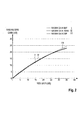
- the signal RBS gain is proportional to the signal SRS gain (i.e., Raman gain) as illustrated in Figure 2 .
- SBS signal stimulated Brillouin scattered
- the signal stimulated Brillouin scattered (SBS) light is avoided by controlling per channel data and supervisory signal launch power into the transmission fiber 3.
- the pump signal SBS is non-existent since the spectral line widths of the pump LDs are very broad.
- the RBS gain versus Raman gain relationship shown in Figure 2 is valid when ASE, data, supervisory or pump signal back reflection is monitored for closed loop gain control. However, when pump back reflection monitoring is used for closed loop gain control, the change in RBS takes a negative sign (i.e., RBS loss versus Raman gain). This is because when pump powers are increased to attain higher Raman gain pump depletion increases proportionally.
- the pumped Raman amplifier 1 according to the present invention as shown in Figure 1A comprises a feedback control loop, wherein the signal gain level can be adjusted to be constant over loss changes.
- the pumped Raman amplifier 1 can use the relationship between the Raman amplified back reflected signal RBS light and the Raman amplified transmitted signal light for different fiber types as illustrated in FiGure 2 .
- the RBS coefficient varies from -29 to -31 dB for different fiber types.
- the RBS gain in Fig 2 is defined as the RBS coefficient normalized to when pump powers are off (no Raman gain). When the loop is closed and the user sets the gain the control loop maintains the back reflection indicated in Fig. 2 .
- the pumped Raman amplifier 1 can monitor the optical pilot signal transmitted in the optical supervisory channel OSC and/or optical data signals transmitted on optical signal channels.
- the gain control unit 4 receives monitoring signals from all monitoring units 8, 18, and 20.
- the input of the gain control unit 4 is switchable between outputs of different monitoring units.
- the pumped Raman amplifier 1 further comprises a feed-forward control loop to control gain saturation over input power changes. It is possible to use the pump power versus signal power relationship for different gain settings and for different fiber types of the transmission line fiber 3. In a possible embodiment a user can enter first a fiber type of the transmission line fiber 3.
- the counter-pumped Raman amplifier 1' is symmetrical structured to the co-pumped Raman amplifier 1 shown in Fig. 1A .
- the counter-pumped Raman amplifier 1' receives at terminal 2' an optical data signal, an optical supervisory OSC signal, backward ASE noise and backscattered pump signal S RX '.
- pump signal S TX ' is transmitted into the transmission line fiber 3.
- the pump signal is counter propagating with respect to the received data signal and supervisory signal.
- the data signal and supervisory signal S IN ' are transmitted into the transmission fiber 3 from a far-end upstream node location.
- the saturation point depends on the gain setting.
- P S input signal power
- the unsaturated gain Go is a function of the fiber parameters of the transmission line fiber 3 and the pump power P P .
- ⁇ P is part of the pump power produced by the FB control signal.
- FB control signal detected by the backscattered supervisory signal channel signal data channel or signal pump channel power from the transmission line fiber 3 a virtual feedback loop can be established.
- a feed-forward loop is established. In using both loops, the speed of the transient response compensation can be significantly increased.
- V s is the FF control voltage
- g k is the conversion factor resulting from the product of the slope efficiency of the k th pump LD and the transconductance gain of the k th DA
- N p is the total number of pump signal channels
- a k is the k th pump signal FF gain adjustment factor
- b k is the k th pump signal FB gain adjustment factor.
- Each pump channel is driven by a different control voltage level.
- the FF and FB gain adjustment factors are stored in the LUT 6 for various gain settings. FF and FB gain adjustment factors are chosen to produce a flat Raman gain spectrum at various gain settings and when signal is transmitted over various fiber types.
- the method according to the present invention it is possible to reduce transient and steady state gain errors when distributed forward Raman amplifiers are operating in a near saturated region.
- the gain of the forward Raman can roll-off beyond a certain input power range.
- the input power range can be extended keeping the gain constant as input signal power increases.
- a further advantage of the method according to the present invention is to reduce transients very rapidly.
- Traffic patterns in a WDM optical communication system can change drastically when wavelengths 7, i.e. channels, are added or removed at the network end terminals or when wavelengths 7 are switched between deployed network fibers or when an optical fiber is cut.
- Optical amplifiers deployed in conventional networks may therefore experience a large optical power variation due to sudden changes of channel loading within the network fiber link.
- Surviving channels will experience large transients, i.e. power surges, if an optical amplifier is not rapidly gain controlled over a given input power dynamic range. Such transients can propagate and accumulate when passing through amplifier cascades within the optical network.
- the method performs a fast dynamic gain control of the forward pumped distributed Raman amplifier 1 when sudden and large signal power variations occur at the input of the transmission line fiber 3.
- a co-pumped Raman amplifier 1 is connected to the transmission line fiber 3 as shown in Fig. 1A .
- the other end of the fiber is where the downstream node is located.
- the downstream node may be a line-amplifier node with an EDFA, or a ROADM node (not shown in Fig 1 A) .
- a line-amplifier node with an EDFA or ROADM node at the upstream node location is connected to the transmission line fiber 3.
- a counter-pumped Raman 1' is connected to the other end of the transmission line fiber 3 as shown in Fig 1B .
- both a co-pumped and counter-pumped Raman amplifier 1, 1' are connected to each end of the transmission line fiber 3.
- pump signals may crosstalk to each other causing the gain control to not work optimally.
- To overcome this one can use different pump channel wavelengths at co- and counter units and use an optical filter inside the pump unit before the back reflection is detected to avoid the leakage.
Landscapes
- Physics & Mathematics (AREA)
- Electromagnetism (AREA)
- Engineering & Computer Science (AREA)
- Plasma & Fusion (AREA)
- Optics & Photonics (AREA)
- Computer Networks & Wireless Communication (AREA)
- Signal Processing (AREA)
- Automation & Control Theory (AREA)
- Optical Modulation, Optical Deflection, Nonlinear Optics, Optical Demodulation, Optical Logic Elements (AREA)
Abstract
a gain control unit adapted to control a pump power of an optical pump signal in response to at least one monitored optical feedback signal reflected back from a transmission line fiber connected to said pumped Raman amplifier.
Description
- A Raman amplifier is a type of optical amplifier used in fiber optic transmission systems. Raman amplification is based on the Stimulated Raman Scattering (SRS) phenomenon where a lower frequency signal photon induces a scattering of a higher frequency pump photon in an optical medium in the nonlinear regime. As a result of this, another signal photon is produced, wherein the surplus energy resonantly passes through the vibrational states of the medium. Raman amplifiers are being deployed in long-haul, regional, and metro-core fiber optic transmission systems. Distributed Raman amplifiers improve the optical signal-to-noise ratio and reduce the nonlinear penalty of fiber systems, allowing for longer reach, longer amplifier spans, higher bit rates, higher number of channels, closer channel spacing and operation near the fiber zero dispersion wavelength. Raman scattering of incoming light with phonons in the lattice of the gain medium produces photons coherent with the incoming photons. In a Raman amplifier the optical signal is amplified by Raman amplification. Unlike the erbium-doped fiber amplifiers (EDFA) or the semiconductor optical amplifiers (SOA) the amplification effect of a Raman amplifier is achieved by a nonlinear interaction between a signal and a pump laser within an optical fiber. Two different types of Raman amplifiers are known, i.e. a distributed and a lumped amplifier. The distributed Raman amplifier is a Raman amplifier in which the transmission line optical fiber is utilized as the gain medium by multiplexing a pump wavelength with a signal wavelength whereas a lumped Raman amplifier utilizes a dedicated, self-contained shorter length of optical fiber to provide amplification. In the case of a lumped Raman amplifier a highly nonlinear fiber with a small core such as dispersion compensating fiber is utilized to increase the interaction between the signal and the pump wavelength. The pump light may be coupled into the transmission fiber in the same direction as the signal (co-directional pumping), in the opposite direction (counter-directional pumping) or in both directions (bi-directional pumping).
- In a conventional optical transmission system large signal variations may occur when data channels are added or are dropped within the network. This can lead to sudden and large signal power variations at the input of the transmission line fiber connected to the Raman amplifier which in turn causes a change in signal gain of the amplified surviving data channels along the transmission line fiber. Accordingly, there is a need for a fast dynamic signal gain control of co- or counter- pumped distributed Raman amplifiers.
- The invention provides a method for controlling signal gain of a pumped Raman amplifier, wherein a pump power of a pump signal of said Raman amplifier is controlled in response to at least one monitored optical feedback signal reflected back, due to Rayleigh scattering, from a transmission line fiber connected to said Raman amplifier.
- In a possible embodiment of the method according to the present invention the pump power of said optical pump signal is further controlled in response to at least one monitored optical feed-forward signal. In a co-pumped Raman amplifier the feed-forward signal is the transmitted signal launched into said transmission line fiber and in a counter-pumped Raman amplifier the feed-forward signal is the received signal detected from said transmission line fiber.
- In a still further possible embodiment of the method according to the present invention the monitored optical signal comprises at least one optical pilot signal transmitted on an optical supervisory channel and/or an optical data signal transmitted on an optical signal channel.
- In a further possible embodiment of the method according to the present invention the at least one monitored optical signal is tapped by means of an optical splitter and converted into a feedback control signal and a feed-forward control signal applied to a pump source unit generating said optical pump signal with the controlled pump power launched into said transmission line fiber connected to said Raman amplifier. In a further possible embodiment of the method according to the present invention the tapped monitored optical signal is converted by a photodetector into an electrical current which is transformed by means of a transimpedance amplifier into a control voltage indicating the signal power of the respective monitored optical signal.
- In a further possible embodiment of the method according to the present invention a control voltage corresponding to a ratio between the signal power of the monitored optical feedback signal and the signal power of the monitored optical feed-forward signal is supplied to at least one proportional, integral and differential (PiD) control circuit which compares the control voltage with a set voltage read from a look-up table in response to a desired Raman gain set by a user to generate a feedback control signal which controls said pump source unit generating said optical pump signal.
- In a further possible embodiment of the method according to the present invention the optical supervisory channel comprises a wavelength band between a pump wavelength band of said optical pump signal and a data signal wavelength band of said optical data signal.
- The invention further provides a pumped Raman amplifier comprising
a gain control circuit adapted to control a pump power of an optical pump signal in response to at least one monitored optical feedback signal reflected back from a transmission line fiber connected to said pumped Raman amplifier. - In a possible embodiment of the method according to the present invention the gain control circuit is further adapted to control the pump power of said optical pump signal in response to at least one monitored optical feed-forward signal launched into said transmission line fiber connected to said pumped Raman amplifier.
- In a further possible embodiment of the method according to the present invention the gain control circuit comprises a PID control circuit which compares a control voltage indicating a ratio between the signal power of the monitored optical feedback signal and the signal power of the monitored optical feed-forward signal with a set voltage read from a look-up table in response to a desired Raman gain set by a user to generate a feedback control signal which controls a pump source unit of said Raman amplifier generating the optical pump signal with the controlled pump power.
- In a further possible embodiment of the method according to the present invention the gain control circuit comprises a PID control circuit which compares a control voltage indicating the signal power of the monitored optical feedback signal with a set voltage read from a look-up table in response to a desired Raman gain set by a user to generate a feedback control signal which controls a pump source unit of said Raman amplifier generating the optical pump signal with the controlled pump power.
- One can choose to use either the ratio or the absolute back reflection. For example, in a co-pumped Raman amplifier if a data or supervisory signal monitor unit is used for feedback control voltage then one can use a ratio of the power mentioned i.e., VRBS. In a co- or counter-pumped Raman amplifier If one uses the pump signal monitor unit the absolute back reflection for feedback control voltage i.e., VBR can be used. For feed-forward control the data signal voltage Vs is used.
In a further possible embodiment of the pumped Raman amplifier according to the present invention the pumped Raman amplifier further comprises: - a first monitoring unit adapted to monitor at least one optical pilot signal transmitted in an optical supervisory channel.
- In a further possible embodiment of the pumped Raman amplifier according to the present invention the pumped Raman amplifier further comprises a second monitoring unit adapted to monitor an optical data signal transmitted on an optical data channel.
- In a still further possible embodiment of the pumped Raman amplifier according to the present invention the pumped Raman amplifier further comprises a third monitoring unit adapted to monitor an optical pump signal generated by said pump source unit being controlled by said gain control circuit.
- In a further possible embodiment of the pumped Raman amplifier according to the present invention each monitoring unit is connected to
an optical splitter adapted to tap the respective monitored optical signal,
at least one photodetector adapted to convert the tapped optical signal into an electrical current, wherein said monitoring unit comprises
at least one transimpedance amplifier adapted to transform said electrical current into a control voltage indicating a signal power of the monitored optical signal. - In a further possible embodiment of the pumped Raman amplifier according to the present invention the gain control circuit comprises feedback gain adjustment means to adjust the feedback control signal provided by the PID control circuit and feed-forward gain adjustment means to adjust a feed-forward control signal provided by a monitoring unit of said pumped Raman amplifier.
- In a still further possible embodiment of the pumped Raman amplifier according to the present invention the gain control circuit further comprises at least one signal adder adapted to add the adjusted feedback control signal and the adjusted feed-forward control signal to generate a signal supplied to a driver amplifier of said pump source unit, wherein said driver amplifier is adapted to amplify the signal and to supply the amplified signal to a laser diode of said pump source unit.
- The invention further provides a gain control unit for a pumped Raman amplifier, wherein said gain control circuit is adapted to control a pump power of an optical pump signal in response to at least one monitored optical feedback signal reflected back from a transmission line fiber connected to said pumped Raman amplifier.
- In a possible embodiment of the gain control unit according to the present invention the gain control circuit is further adapted to control the pump power of the optical pump signal in response to at least one monitored optical feed-forward signal launched into said transmission line fiber connected to said pumped Raman amplifier.
- In the following possible embodiments of the method and apparatus for controlling a signal gain of a pumped Raman amplifier are described with reference to the enclosed figures.
- Figs. 1 A, 1B
- show block diagrams of possible implementations of a pumped Raman amplifier employing the method according to the present invention;
- Fig. 2
- shows a plot of change in back reflected optical power under different Raman gain set-points of a pumped Raman amplifier according to the present invention.
-
Fig. 1A shows a possible implementation of a pumpedRaman amplifier 1 according to the present invention, wherein the pumpedRaman amplifier 1 is formed by a co-pumped Raman amplifier connected via itssignal output 2 to atransmission line fiber 3 as illustrated inFig. 1A. Fig. 1B shows a further possible implementation of the pumped Raman amplifier, wherein the pumped Raman amplifier is formed by a counter-pumped Raman amplifier 1'. As can be seen both Ramanamplifiers 1, 1' shown inFigs 1A ,1B are symmetrical in their circuit structure. The pumped Ramanamplifier 1 comprises again control unit 4 adapted to control a pump power of an optical pump signal in response to at least one monitored optical feedback signal reflected back from thetransmission line fiber 3 connected to the pumpedRaman amplifier 1. Thegain control unit 4 is further adapted to control the pump power of the optical pump signal in response to at least to one monitored optical feed-forward signal launched into saidtransmission line fiber 3 connected to the pumpedRaman amplifier 1. As can be seen inFig. 1A thegain control unit 4 comprises in the shown implementation aPID control circuit 5 which compares a control voltage VRBS or VBR applied through aswitching unit 30. The control voltage VBR indicates the optical signal power of the monitored optical feedback signal and the control voltage VRBS indicates a ratio between the optical signal power of the monitored optical feedback signal and the optical signal power of the monitored optical forward signal. The control voltage is compared with a set voltage Vset read from a look-up table 6 in response to a desired Raman gain set by a user to generate a feedback (FB) control signal which controls a pump source unit 7 of saidRaman amplifier 1 generating the optical pump signal with the controlled pump power. The control voltage VRBS can be generated by the ratio of the optical power of the monitored optical feedback signal which can be the pump signal, a data signal or supervisory signal and the optical power of the monitored optical forward signal which can be also a pump signal, data signal or supervisory signal, respectively. The control voltage VBR can be generated by the optical power of the monitored optical feedback signal which can be the pump signal, data signal or pilot/supervisory signal.
The look up table (LUT) 6 can be stored in a data storage which forms part of theRaman amplifier 1 or to which theRaman amplifier 1 has access via a data network. - As can be seen from
Fig. 1A the pumpedRaman amplifier 1 comprises in the shown implementation several monitoring units. - A
first monitoring unit 8 is adapted to monitor at least one optical pilot signal transmitted in an optical supervisory channel OSC. The pumpedRaman amplifier 1 receives the optical pilot signal SOSC-IN at aninput 9. Theinput 9 of the pumpedRaman amplifier 1 can, for example, be connected to a transceiver of a central office within in the optical telecommunication system. The received optical pilot signal passes through a variableoptical attenuator VOA 10, an optionaloptical isolator 11 and an optical two-by-twosplitter 12 as shown inFig. 1 . Theoptical splitter 12 is connected to thefirst monitoring unit 8. Theoptical splitter 12 is adapted to tap the monitored optical pilot signal transmitted in the optical supervisory channel OSC. Theoptical splitter 12 is connected to an OSCsignal WDM multiplexer 13 which can be formed by an optical filter wherein themultiplexer 13 is adapted to combine the optical pilot signal with a communication signal which can comprise, for example, 1 - 96 different wavelengths λ. The OSCsignal WDM multiplexer 13, is connected to a signalpump WDM multiplexer 14 which in turn is connected to thesignal output 2 of theco-pumped Raman amplifier 1 as illustrated inFig. 1A . At thesignal output 2 pump signal, the data signal and the OSC supervisory signal are output and transmitted via thetransmission line fiber 3 as transmission signals STX. At theoutput 2, the backscattered pump signal, data signal, supervisory signal and backward propagating ASE noise are received from thetransmission line fiber 3 as received signals SRX.
The pumpedRaman amplifier 1 has further asignal input 15 for receiving an optical data signal Sin transmitted on an optical data channel. This optical data signal is supplied via anoptical isolator 16 to a furtheroptical splitter 17 shown inFig. 1A . Theoptical splitter 17 can be a two-by-two optical splitter adapted to tap the respective monitored optical signal. Theoptical splitter 17 is connected to the OSCsignal WDM multiplexer 13. The OSCsignal WDM multiplexer 13 multiplexes the optical data signal transmitted on one or several optical data channels with the at least one optical pilot signal transmitted on the optical supervisory channel OSC. The secondoptical splitter 17 is connected to a secondsignal monitoring unit 18 which is adapted to monitor the optical data signals transmitted on the optical data channels. Theoptical splitter 17 taps the respective monitored optical signal and supplies the tapped monitored optical data signal to thesignal monitoring unit 18. - The signal
pump WDM multiplexer 14 is adapted to multiplex the output signal of the OSCsignal WDM multiplexer 13 with the pump signal supplied to thesignal pump WDM 14 via a thirdoptical splitter 19 from a pump source unit 7. The thirdoptical splitter 19 can be formed by a two-by-two optical splitter as shown inFig. 1A . Theoptical splitter 19 is connected to athird monitoring unit 20 adapted to monitor an optical pump signal generated by the pump source unit 7. The pump source unit 7 is controlled by thegain control unit 4 as shown inFig. 1A . Accordingly, in the embodiment ofFig. 1 the pumped Raman amplifier 1 A comprises afirst monitoring unit 8 adapted to monitor at least one optical pilot signal transmitted in an optical supervisory channel OSC, asecond monitoring unit1 18 adapted to monitor an optical data signal transmitted on an optical data channel and athird monitoring unit 20 adapted to monitor an optical pump signal generated by the pump source unit 7. Each monitoring unit is connected to an optical splitter adapted to tap the respective monitored optical signal. Eachmonitoring unit - The pump source unit 7 comprises driver amplifiers DAs, for laser diodes LDs. The laser diodes LDs are connected via polarization beam combiners PBCs to a
pump WDM multiplexer 21 supplying the pump signal via theoptical splitter 19 to the signalpump WDM multiplexer 14 of the pumpedRaman amplifier 1 as shown inFig. 1A . - The
gain control unit 4 receives control voltage signals from the first, second andthird monitoring units Fig. 1A thegain control unit 4 comprises aPID control circuit 5 which compares a control voltage VRBS indicating a ratio between the signal power of the monitored optical feedback signal and the signal power of the monitored optical feed-forward signal with a set voltage Vset read from the look-up table 6 connected to aninput 22a of the pumpedRaman amplifier 1. The look up table 6 can be connected to a user interface UI where a user can set a desired Raman gain to generate a feedback (FB) control signal which controls the pump source unit 7 of said pumpedRaman amplifier 1. As can be seen inFig. 1A thegain control unit 4 further receives a feed-forward (FF) control signal provided by a monitoring unit of the pumpedRaman amplifier 1. The feed-forward (FF) control signal is supplied to afirst switching unit 23 of thegain control unit 4. The feedback FB control signal provided by thePID control circuit 5 of thegain control unit 4 is supplied to asecond switching unit 24 of thegain control unit 4. Thesecond switching unit 24 has two inputs, wherein the first input is connected to the output of thePID control circuit 5 and the second input is connected to areference unit 25 providing a reference voltage V0. - An integrated
mode control circuit 26 controls the first andsecond switching unit gain control unit 4 to switch between different operation modes of thegain control unit 4. In a possible operation mode the pump power of the pump signal is controlled in response to the monitored optical feedback signal reflected back from thetransmission line fiber 3 connected to theRaman amplifier 1. In a further possible operation mode the pump power of the optical pump signal is controlled in response to the monitored optical feedback signal and in response to the monitored optical feed-forward signal launched into saidtransmission line fiber 3. - In a possible embodiment the
gain control unit 4 comprises feedback gain adjustment means 27 to adjust the feedback FB control signal output by the switchingunit 24 and feed-forward gain adjustment means 28 to adjust a feed-forward FF control signal output by thesecond switching unit 23. The feedback gain applied by the feedback gain adjustment means 27 and the feed forward gain applied by the feed forward gain adjustment means 28 are read from the look-up table (LUT) 6 viaterminals gain control unit 4 further comprises at least one signal adder 29 adapted to add the adjusted feedback control signal and the adjusted feed-forward control signal to generate a signal supplied to a driver amplifier DA of the pump source unit 7 as shown infig. 1A . The driver amplifier DA of the pump source unit 7 is adapted to amplify the signal and to supply the amplified signal to a laser diode LD of the pump source unit 7. - With the method according to the present invention it is possible to dynamically control the signal gain and saturation of the forward
co-pumped Raman amplifier 1 shown inFig. 1A . The Raman control employing the method according to the present invention can employ both, the signal light launched into thetransmission line fiber 3 and the amplified signal Rayleigh backscattered (RBS) light reflected back from thetransmission line fiber 3. The signal light launched into thetransmission line fiber 3 is used for a feed-forward pump control. The signal light back-reflected (RBS) from thetransmission line fiber 3 is used as a virtual feedback pump control signal. The transmitted forward signal light is data signal channels, pump signal channels and supervisory signal channel. The signal RBS light is composed of back-reflected data signal, pump signal and supervisory signal. The signal RBS light such as the data signal and supervisory signal is amplified by the Raman gain as the pump power is increased while the pump signal is depleted. The signal RBS gain is proportional to the signal SRS gain (i.e., Raman gain) as illustrated inFigure 2 . This makes it possible to employ the virtual feedback control employed by the method according to the present invention. The signal stimulated Brillouin scattered (SBS) light is avoided by controlling per channel data and supervisory signal launch power into thetransmission fiber 3. The pump signal SBS is non-existent since the spectral line widths of the pump LDs are very broad. The RBS gain versus Raman gain relationship shown inFigure 2 is valid when ASE, data, supervisory or pump signal back reflection is monitored for closed loop gain control. However, when pump back reflection monitoring is used for closed loop gain control, the change in RBS takes a negative sign (i.e., RBS loss versus Raman gain). This is because when pump powers are increased to attain higher Raman gain pump depletion increases proportionally. - The pumped
Raman amplifier 1 according to the present invention as shown inFigure 1A comprises a feedback control loop, wherein the signal gain level can be adjusted to be constant over loss changes. The pumpedRaman amplifier 1 can use the relationship between the Raman amplified back reflected signal RBS light and the Raman amplified transmitted signal light for different fiber types as illustrated inFiGure 2 . The RBS coefficient varies from -29 to -31 dB for different fiber types. The RBS gain inFig 2 is defined as the RBS coefficient normalized to when pump powers are off (no Raman gain). When the loop is closed and the user sets the gain the control loop maintains the back reflection indicated inFig. 2 . - The pumped
Raman amplifier 1 can monitor the optical pilot signal transmitted in the optical supervisory channel OSC and/or optical data signals transmitted on optical signal channels. In a possible implementation thegain control unit 4 receives monitoring signals from all monitoringunits gain control unit 4 is switchable between outputs of different monitoring units. - The pumped
Raman amplifier 1 according to the present invention further comprises a feed-forward control loop to control gain saturation over input power changes. It is possible to use the pump power versus signal power relationship for different gain settings and for different fiber types of thetransmission line fiber 3. In a possible embodiment a user can enter first a fiber type of thetransmission line fiber 3. - As shown in
Fig. 1B the counter-pumped Raman amplifier 1' is symmetrical structured to theco-pumped Raman amplifier 1 shown inFig. 1A . The counter-pumped Raman amplifier 1' receives at terminal 2' an optical data signal, an optical supervisory OSC signal, backward ASE noise and backscattered pump signal SRX'. At terminal 2', pump signal STX' is transmitted into thetransmission line fiber 3. - The pump signal is counter propagating with respect to the received data signal and supervisory signal. The data signal and supervisory signal SIN' are transmitted into the
transmission fiber 3 from a far-end upstream node location. - The saturation point depends on the gain setting. The saturated large signal gain expression is given by:

wherein G0 is the unsaturated (small signal) gain,
PS is the signal power at the fiber input of thetransmission line fiber 3,
PP is the pump power at the fiber input of thetransmission line fiber 3,
λ S and λP are the signal and pump wavelength, respectively. - The saturation signal power is:

A low input signal power (PS <<Psat) the Raman gain is almost constant. However, the Raman gain does decrease as the input signal power PS increases, for example, due to adding or dropping channels. - The unsaturated gain Go is a function of the fiber parameters of the
transmission line fiber 3 and the pump power PP. The unsaturated gain can be expressed as follows:
where CR is the Raman gain efficiency and Leff is the effective fiber length. - The expression of the pump power Pp that is required to control gain saturation, i.e, to extend the input signal power range with a constant and spectrally flat gain, in the feed-forward control mode of the
Raman amplifier 1, can be derived as follows:
- This expression can be simplified further as:

where:
and P0 is the required pump power to attain the small-signal gain Go. At various gain settings the FF and FB gain coefficients are adjusted with the switchingunit 24 switched to thereference voltage unit 25. The FB loop is engaged when the switchingunit 24 is switched to the PID output. The expression including feedback (FB) control can be further simplified as:
- Where ΔPis part of the pump power produced by the FB control signal. With the method according to the present invention FB control signal detected by the backscattered supervisory signal channel, signal data channel or signal pump channel power from the transmission line fiber 3 a virtual feedback loop can be established. By detecting the input data signal power a feed-forward loop is established. In using both loops, the speed of the transient response compensation can be significantly increased. The total transmitted pump power is related to the control voltage as follows:

- Where Vs is the FF control voltage, ΔV=VSet-VBR (or =Vset-VBRS) is the FB control voltage, gk is the conversion factor resulting from the product of the slope efficiency of the kth pump LD and the transconductance gain of the kth DA, Np is the total number of pump signal channels, ak is the kth pump signal FF gain adjustment factor and bk is the kth pump signal FB gain adjustment factor. Each pump channel is driven by a different control voltage level. The FF and FB gain adjustment factors are stored in the LUT 6 for various gain settings. FF and FB gain adjustment factors are chosen to produce a flat Raman gain spectrum at various gain settings and when signal is transmitted over various fiber types.
- With the method according to the present invention it is possible to reduce transient and steady state gain errors when distributed forward Raman amplifiers are operating in a near saturated region. In an open loop the gain of the forward Raman can roll-off beyond a certain input power range. When the loop is closed the input power range can be extended keeping the gain constant as input signal power increases.
- A further advantage of the method according to the present invention is to reduce transients very rapidly. Traffic patterns in a WDM optical communication system can change drastically when wavelengths 7, i.e. channels, are added or removed at the network end terminals or when wavelengths 7 are switched between deployed network fibers or when an optical fiber is cut. Optical amplifiers deployed in conventional networks may therefore experience a large optical power variation due to sudden changes of channel loading within the network fiber link. Surviving channels will experience large transients, i.e. power surges, if an optical amplifier is not rapidly gain controlled over a given input power dynamic range. Such transients can propagate and accumulate when passing through amplifier cascades within the optical network. When the surviving channels are received at the end terminals the rapid power variations can generate error bursts which will degrade the signal quality. With the method and apparatus according to the present invention it is possible to reduce these kinds of transients very rapidly. The method performs a fast dynamic gain control of the forward pumped distributed
Raman amplifier 1 when sudden and large signal power variations occur at the input of thetransmission line fiber 3. - There are three configurations when using pumped Raman amplifiers connected to the
transmission line fiber 3.
In a first co-pumped Raman configuration , only aco-pumped Raman amplifier 1 is connected to thetransmission line fiber 3 as shown inFig. 1A . The other end of the fiber is where the downstream node is located. The downstream node may be a line-amplifier node with an EDFA, or a ROADM node (not shown inFig 1 A) .
In a second counter-pumped Raman configuration a line-amplifier node with an EDFA or ROADM node at the upstream node location is connected to thetransmission line fiber 3. A counter-pumped Raman 1' is connected to the other end of thetransmission line fiber 3 as shown inFig 1B .
In a third bi-directional pumped Raman configuration both a co-pumped andcounter-pumped Raman amplifier 1, 1' are connected to each end of thetransmission line fiber 3. When using this configuration pump signals may crosstalk to each other causing the gain control to not work optimally. To overcome this one can use different pump channel wavelengths at co- and counter units and use an optical filter inside the pump unit before the back reflection is detected to avoid the leakage.
Claims (16)
- A method for controlling a signal gain of a pumped Raman amplifier,
wherein a pump power of a pump signal of said Raman amplifier is controlled in response to at least one monitored optical feedback signal reflected back from a transmission line fiber connected to said Raman amplifier. - The method according to claim 1,
wherein the pump power of said optical pump signal is further controlled in response to at least one monitored optical feed-forward signal launched into said transmission line fiber. - The method according to claim 1,
wherein said monitored optical signal comprises at least one optical pilot signal transmitted on an optical supervisory channel and
an optical data signal transmitted on an optical signal channel. - The method according to claim 1,
wherein said at least one monitored optical signal is tapped by means of an optical splitter and converted into a feedback control signal and a feed-forward control signal applied to a pump source unit generating said optical pump signal with the controlled pump power launched into said transmission line fiber connected to said Raman amplifier. - The method according to claim 4,
wherein the tapped monitored optical signal is converted by a photodetector into an electrical current which is transformed by means of a transimpedance amplifier into a control voltage indicating the signal power of the respective monitored optical signal. - The method according to claim 5,
wherein a control voltage corresponding to a ratio between the signal power of the monitored optical feedback signal and the signal power of the monitored optical feed-forward signal is supplied to at least one PID control circuit which compares said control voltage with a set voltage read from a look-up table in response to a desired Raman gain set by a user to generate a feedback control signal which controls said pump source unit generating said optical pump signal. - The method according to claim 3,
wherein said optical supervisory channel comprises a wavelength band between a pump wavelength band of said optical pump signal and a data signal wavelength band of said optical data signal. - A pumped Raman amplifier comprising
a gain control unit adapted to control a pump power of an optical pump signal in response to at least one monitored optical feedback signal reflected back from a transmission line fiber connected to said pumped Raman amplifier. - The pumped Raman amplifier according to claim 8,
wherein said gain control unit is further adapted to control said pump power of said optical pump signal in response to at least one monitored optical feed-forward signal launched into said transmission line fiber connected to said pumped Raman amplifier. - The pumped Raman amplifier according to claim 8,
wherein said gain control unit comprises a PID control circuit which compares a control voltage indicating a ratio between the signal power of the monitored optical feedback signal and the signal power of the monitored optical feed-forward signal with a set voltage read from a look-up table in response to a desired Raman gain set by a user to generate a feedback control signal which controls a pump source unit of said Raman amplifier generating the optical pump signal with the controlled pump power. - The pumped Raman amplifier according to claim 10,
wherein said pumped Raman amplifier further comprises:a first monitoring unit adapted to monitor at least one optical pilot signal transmitted in an optical supervisory channel;a second monitoring unit adapted to monitor an optical data signal transmitted on an optical data channel; anda third monitoring unit adapted to monitor an optical pump signal generated by said pump source unit being controlled by said gain control unit. - The pumped Raman amplifier according to claim 11,
wherein each monitoring unit is connected to
an optical splitter adapted to tap the respective monitored optical signal and comprises;
at least one photodetector adapted to convert the tapped optical signal into an electrical current and
at least one transimpedance amplifier adapted to transform said electrical current into a control voltage indicating a signal power of the monitored optical signal. - The pumped Raman amplifier according to claim 12,
wherein said gain control unit comprises feedback gain adjustment means to adjust the feedback control signal provided by said PID control circuit and feed-forward gain adjustment means to adjust a feed-forward control signal provided by a monitoring unit of said pumped Raman amplifier. - The pumped Raman amplifier according to claim 13,
wherein said gain control unit further comprises at least one signal adder adapted to add the adjusted feedback control signal and the adjusted feed-forward control signal to generate a signal supplied to a driver amplifier of said pump source unit, wherein said driver amplifier is adapted to amplify the signal and to supply the amplified signal to a laser diode of said pump source unit. - A gain control unit for a pumped Raman amplifier,
wherein said gain control unit is adapted to control a pump power of an optical pump signal in response to at least one monitored optical feedback signal reflected back from a transmission line fiber connected to said pumped Raman amplifier. - The gain control unit according to claim 15,
wherein said gain control unit is further adapted to control said pump power of said optical pump signal in response to at least one monitored optical feed-forward signal launched into said transmission line fiber connected to said pumped Raman amplifier.
Applications Claiming Priority (1)
| Application Number | Priority Date | Filing Date | Title |
|---|---|---|---|
| US13/419,422 US8854726B2 (en) | 2012-03-13 | 2012-03-13 | Method for controlling signal gain of a Raman amplifier |
Publications (2)
| Publication Number | Publication Date |
|---|---|
| EP2639898A1 true EP2639898A1 (en) | 2013-09-18 |
| EP2639898B1 EP2639898B1 (en) | 2018-01-10 |
Family
ID=47561457
Family Applications (1)
| Application Number | Title | Priority Date | Filing Date |
|---|---|---|---|
| EP13151972.0A Active EP2639898B1 (en) | 2012-03-13 | 2013-01-18 | A method for controlling signal gain of a raman amplifier |
Country Status (2)
| Country | Link |
|---|---|
| US (2) | US8854726B2 (en) |
| EP (1) | EP2639898B1 (en) |
Cited By (4)
| Publication number | Priority date | Publication date | Assignee | Title |
|---|---|---|---|---|
| EP3079275A4 (en) * | 2013-12-31 | 2016-11-30 | Huawei Tech Co Ltd | METHOD, DEVICE, AND BROKEN FIBER DETECTION SYSTEM FOR DISTRIBUTED RAMAN DISPERSION OPTICAL AMPLIFIER |
| CN106936509A (en) * | 2015-12-29 | 2017-07-07 | 海思光电子有限公司 | A kind of Raman transient effect control method and device |
| EP3217574A1 (en) * | 2016-03-09 | 2017-09-13 | Xieon Networks S.à r.l. | A bidirectional and configurable directional raman pumping apparatus |
| CN109103741A (en) * | 2018-09-04 | 2018-12-28 | 武汉光迅科技股份有限公司 | A kind of gain dynamic control method of Raman Fiber Amplifier, device and system |
Families Citing this family (4)
| Publication number | Priority date | Publication date | Assignee | Title |
|---|---|---|---|---|
| JP6694754B2 (en) * | 2016-05-16 | 2020-05-20 | 株式会社フジクラ | Laser device and laser system |
| EP3300265B1 (en) * | 2016-09-22 | 2018-12-26 | Xieon Networks S.à r.l. | Raman pumping arrangement with improved osc sensitivity |
| JP7464841B2 (en) * | 2020-08-04 | 2024-04-10 | 富士通株式会社 | Raman amplifier control device and control method |
| JP7871662B2 (en) * | 2022-09-08 | 2026-06-09 | 1Finity株式会社 | Optical transmission device, optical transmission system, and control method for a Raman amplifier |
Citations (7)
| Publication number | Priority date | Publication date | Assignee | Title |
|---|---|---|---|---|
| WO2002017520A1 (en) * | 2000-08-18 | 2002-02-28 | Corning Incorporated | Gain control in raman amplifiers |
| EP1298764A2 (en) * | 2001-09-28 | 2003-04-02 | Fujitsu Limited | Method and device for optical amplification |
| US20040075887A1 (en) * | 2002-06-04 | 2004-04-22 | Eiselt Michael H. | Apparatus and method for raman gain control |
| US6850360B1 (en) * | 2001-04-16 | 2005-02-01 | Bookham, Inc. | Raman amplifier systems with diagnostic capabilities |
| US20050024712A1 (en) * | 2003-08-01 | 2005-02-03 | Fujitsu Limited | Raman amplifier and raman amplifier adjustment method |
| US20070258132A1 (en) * | 2006-05-02 | 2007-11-08 | At&T Corp. | Improved feedback dynamic gain control for a wdm system employing multi wavelength pumped raman fiber amplifiers |
| EP1916565A1 (en) * | 2005-06-20 | 2008-04-30 | Fujitsu Ltd. | Raman light amplifier |
Family Cites Families (13)
| Publication number | Priority date | Publication date | Assignee | Title |
|---|---|---|---|---|
| JP2001235772A (en) | 2000-02-22 | 2001-08-31 | Sumitomo Electric Ind Ltd | Raman amplification control device and optical transmission system |
| JP2002040495A (en) * | 2000-07-21 | 2002-02-06 | Sumitomo Electric Ind Ltd | Raman amplifier |
| EP1229381A4 (en) * | 2000-09-07 | 2005-11-30 | Fujitsu Ltd | OPTICAL AMPLIFIER AND OPTICAL COMMUNICATION SYSTEM |
| US6433922B1 (en) * | 2001-02-26 | 2002-08-13 | Redc Optical Networks Ltd. | Apparatus and method for a self adjusting Raman amplifier |
| JP4632585B2 (en) * | 2001-07-16 | 2011-02-16 | 富士通株式会社 | Optical transmission system |
| JP3808766B2 (en) * | 2001-12-21 | 2006-08-16 | 富士通株式会社 | Raman amplifier and optical transmission system |
| JP2003298527A (en) * | 2002-04-02 | 2003-10-17 | Fujitsu Ltd | Method and apparatus for optical fiber transmission using Raman amplification |
| US6963681B2 (en) * | 2002-07-01 | 2005-11-08 | Jds Uniphase Corporation | Automatic raman gain control |
| JP2004080301A (en) * | 2002-08-15 | 2004-03-11 | Kddi Submarine Cable Systems Inc | Monitoring method and system for distributed Raman optical transmission line |
| JP2004289811A (en) * | 2003-03-04 | 2004-10-14 | Sumitomo Electric Ind Ltd | Optical transmission system |
| JP4558425B2 (en) * | 2003-09-08 | 2010-10-06 | 古河電気工業株式会社 | Raman amplifier, excitation source for use in Raman amplifier, method for amplifying optical signal |
| US20070103766A1 (en) * | 2004-10-26 | 2007-05-10 | Frriedrich Lars | Method for monitoring an optical transmission line by means of an optical amplifier and optical amplifier therefor |
| US7142356B2 (en) * | 2005-02-24 | 2006-11-28 | At&T Corp. | Fast dynamic gain control in an optical fiber amplifier |
-
2012
- 2012-03-13 US US13/419,422 patent/US8854726B2/en active Active
-
2013
- 2013-01-18 EP EP13151972.0A patent/EP2639898B1/en active Active
-
2014
- 2014-06-09 US US14/299,418 patent/US9379513B2/en active Active
Patent Citations (7)
| Publication number | Priority date | Publication date | Assignee | Title |
|---|---|---|---|---|
| WO2002017520A1 (en) * | 2000-08-18 | 2002-02-28 | Corning Incorporated | Gain control in raman amplifiers |
| US6850360B1 (en) * | 2001-04-16 | 2005-02-01 | Bookham, Inc. | Raman amplifier systems with diagnostic capabilities |
| EP1298764A2 (en) * | 2001-09-28 | 2003-04-02 | Fujitsu Limited | Method and device for optical amplification |
| US20040075887A1 (en) * | 2002-06-04 | 2004-04-22 | Eiselt Michael H. | Apparatus and method for raman gain control |
| US20050024712A1 (en) * | 2003-08-01 | 2005-02-03 | Fujitsu Limited | Raman amplifier and raman amplifier adjustment method |
| EP1916565A1 (en) * | 2005-06-20 | 2008-04-30 | Fujitsu Ltd. | Raman light amplifier |
| US20070258132A1 (en) * | 2006-05-02 | 2007-11-08 | At&T Corp. | Improved feedback dynamic gain control for a wdm system employing multi wavelength pumped raman fiber amplifiers |
Cited By (10)
| Publication number | Priority date | Publication date | Assignee | Title |
|---|---|---|---|---|
| EP3079275A4 (en) * | 2013-12-31 | 2016-11-30 | Huawei Tech Co Ltd | METHOD, DEVICE, AND BROKEN FIBER DETECTION SYSTEM FOR DISTRIBUTED RAMAN DISPERSION OPTICAL AMPLIFIER |
| US10135525B2 (en) | 2013-12-31 | 2018-11-20 | Huawei Technologies Co., Ltd. | Fiber-cut detection method, apparatus, and system for distributed Raman fiber amplifier |
| CN106936509A (en) * | 2015-12-29 | 2017-07-07 | 海思光电子有限公司 | A kind of Raman transient effect control method and device |
| CN106936509B (en) * | 2015-12-29 | 2020-04-28 | 海思光电子有限公司 | Raman transient effect control method and device |
| EP3217574A1 (en) * | 2016-03-09 | 2017-09-13 | Xieon Networks S.à r.l. | A bidirectional and configurable directional raman pumping apparatus |
| WO2017153517A1 (en) * | 2016-03-09 | 2017-09-14 | Xieon Networks S.À R.L. | A bidirectional and configurable directional raman pumping apparatus |
| US11476938B2 (en) | 2016-03-09 | 2022-10-18 | Xieon Networks S.A.R.L. | Bidirectional and configurable directional Raman pumping apparatus |
| CN109103741A (en) * | 2018-09-04 | 2018-12-28 | 武汉光迅科技股份有限公司 | A kind of gain dynamic control method of Raman Fiber Amplifier, device and system |
| CN109103741B (en) * | 2018-09-04 | 2019-11-26 | 武汉光迅科技股份有限公司 | A kind of gain dynamic control method of Raman Fiber Amplifier, device and system |
| US12074407B2 (en) | 2018-09-04 | 2024-08-27 | Accelink Technologies Co., Ltd. | Method, device and system for dynamically controlling gain of Raman optical fiber amplifier |
Also Published As
| Publication number | Publication date |
|---|---|
| US9379513B2 (en) | 2016-06-28 |
| US20140285874A1 (en) | 2014-09-25 |
| EP2639898B1 (en) | 2018-01-10 |
| US8854726B2 (en) | 2014-10-07 |
| US20130242379A1 (en) | 2013-09-19 |
Similar Documents
| Publication | Publication Date | Title |
|---|---|---|
| US9379513B2 (en) | Method for controlling signal gain of a raman amplifier | |
| US6639715B2 (en) | Raman amplifier and optical transmission system using the amplifier | |
| EP1603257B1 (en) | Optical transmission device and optical communication system | |
| US6341034B1 (en) | Optical amplifier system with transient control using spectrally filtered input | |
| US6498677B1 (en) | Optical amplifier systems with transient control | |
| US6476961B1 (en) | Optical amplifier systems with transient control | |
| CA2649501C (en) | Improved feedback dynamic gain control for a wdm system employing multi-wavelength-pumped raman fiber amplifiers | |
| US10135536B2 (en) | Transmitter optical signal to noise ratio improvement through receiver amplification in single laser coherent systems | |
| US7554719B2 (en) | Fast dynamic gain control in an optical fiber amplifier | |
| EP1385280B1 (en) | Raman amplifier | |
| US7554718B2 (en) | Fast dynamic gain control in an optical fiber amplifier | |
| US20140139908A1 (en) | Methods and devices for efficient optical fiber amplifiers | |
| US9184852B2 (en) | Receiving device and receiving method | |
| KR100474690B1 (en) | Long wavelength optical fiber amplifer | |
| EP3654552A1 (en) | Tilt control through optical pump power adjustment | |
| Kitamura et al. | First experimental demonstration of all-optical feedforward automatic gain control scheme using a semiconductor optical amplifier | |
| JP4695713B2 (en) | Raman amplifier and optical transmission system using the same | |
| EP1696524B1 (en) | Fast dynamic gain control in an optical fiber amplifier | |
| Chung et al. | Reduction of relaxation oscillations in optical automatic gain clamped EDFA using fast electronic feedforward | |
| EP2081308B1 (en) | Method and device for providing and/or controlling an optical signal | |
| Kitamura et al. | All-optical feedforward automatic gain control scheme for pump power shared erbium-doped fiber amplifiers | |
| KR100727636B1 (en) | Automatic Gain Control Optical Amplification System | |
| JP2001060917A (en) | WDM optical transmitter and optical amplifier | |
| Lee et al. | An automatic gain-controlled Raman/gain-clamped SOA for metro WDM networks with changes in span loss | |
| Lopez | Optically gain clamped Erbium-doped fibre amplifiers for next generation optical networks |
Legal Events
| Date | Code | Title | Description |
|---|---|---|---|
| PUAI | Public reference made under article 153(3) epc to a published international application that has entered the european phase |
Free format text: ORIGINAL CODE: 0009012 |
|
| AK | Designated contracting states |
Kind code of ref document: A1 Designated state(s): AL AT BE BG CH CY CZ DE DK EE ES FI FR GB GR HR HU IE IS IT LI LT LU LV MC MK MT NL NO PL PT RO RS SE SI SK SM TR |
|
| AX | Request for extension of the european patent |
Extension state: BA ME |
|
| RIN1 | Information on inventor provided before grant (corrected) |
Inventor name: ATLAS, DOGAN Inventor name: TALEGHANI, MOHAMMAD Inventor name: MAHBOBZADEH, MOHAMMAD Inventor name: HAMILTON, KYLE |
|
| 17P | Request for examination filed |
Effective date: 20140114 |
|
| RBV | Designated contracting states (corrected) |
Designated state(s): AL AT BE BG CH CY CZ DE DK EE ES FI FR GB GR HR HU IE IS IT LI LT LU LV MC MK MT NL NO PL PT RO RS SE SI SK SM TR |
|
| 17Q | First examination report despatched |
Effective date: 20140225 |
|
| STAA | Information on the status of an ep patent application or granted ep patent |
Free format text: STATUS: EXAMINATION IS IN PROGRESS |
|
| GRAP | Despatch of communication of intention to grant a patent |
Free format text: ORIGINAL CODE: EPIDOSNIGR1 |
|
| STAA | Information on the status of an ep patent application or granted ep patent |
Free format text: STATUS: GRANT OF PATENT IS INTENDED |
|
| RIC1 | Information provided on ipc code assigned before grant |
Ipc: H01S 3/131 20060101ALI20170830BHEP Ipc: H01S 3/0941 20060101ALN20170830BHEP Ipc: H04B 10/071 20130101ALI20170830BHEP Ipc: H04B 10/291 20130101ALI20170830BHEP Ipc: H01S 3/30 20060101ALI20170830BHEP Ipc: H01S 3/067 20060101AFI20170830BHEP Ipc: H01S 3/13 20060101ALI20170830BHEP Ipc: H01S 3/094 20060101ALI20170830BHEP Ipc: H01S 3/10 20060101ALI20170830BHEP Ipc: H04B 10/296 20130101ALN20170830BHEP Ipc: H04B 10/293 20130101ALI20170830BHEP |
|
| RIC1 | Information provided on ipc code assigned before grant |
Ipc: H01S 3/10 20060101ALI20170904BHEP Ipc: H01S 3/067 20060101AFI20170904BHEP Ipc: H01S 3/131 20060101ALI20170904BHEP Ipc: H04B 10/071 20130101ALI20170904BHEP Ipc: H01S 3/30 20060101ALI20170904BHEP Ipc: H01S 3/13 20060101ALI20170904BHEP Ipc: H04B 10/296 20130101ALN20170904BHEP Ipc: H04B 10/293 20130101ALI20170904BHEP Ipc: H01S 3/094 20060101ALI20170904BHEP Ipc: H01S 3/0941 20060101ALN20170904BHEP Ipc: H04B 10/291 20130101ALI20170904BHEP |
|
| INTG | Intention to grant announced |
Effective date: 20170922 |
|
| GRAS | Grant fee paid |
Free format text: ORIGINAL CODE: EPIDOSNIGR3 |
|
| GRAA | (expected) grant |
Free format text: ORIGINAL CODE: 0009210 |
|
| STAA | Information on the status of an ep patent application or granted ep patent |
Free format text: STATUS: THE PATENT HAS BEEN GRANTED |
|
| AK | Designated contracting states |
Kind code of ref document: B1 Designated state(s): AL AT BE BG CH CY CZ DE DK EE ES FI FR GB GR HR HU IE IS IT LI LT LU LV MC MK MT NL NO PL PT RO RS SE SI SK SM TR |
|
| REG | Reference to a national code |
Ref country code: CH Ref legal event code: EP Ref country code: AT Ref legal event code: REF Ref document number: 963409 Country of ref document: AT Kind code of ref document: T Effective date: 20180115 |
|
| REG | Reference to a national code |
Ref country code: IE Ref legal event code: FG4D |
|
| REG | Reference to a national code |
Ref country code: DE Ref legal event code: R096 Ref document number: 602013032026 Country of ref document: DE |
|
| REG | Reference to a national code |
Ref country code: NL Ref legal event code: MP Effective date: 20180110 |
|
| REG | Reference to a national code |
Ref country code: AT Ref legal event code: MK05 Ref document number: 963409 Country of ref document: AT Kind code of ref document: T Effective date: 20180110 |
|
| PG25 | Lapsed in a contracting state [announced via postgrant information from national office to epo] |
Ref country code: NL Free format text: LAPSE BECAUSE OF FAILURE TO SUBMIT A TRANSLATION OF THE DESCRIPTION OR TO PAY THE FEE WITHIN THE PRESCRIBED TIME-LIMIT Effective date: 20180110 |
|
| PG25 | Lapsed in a contracting state [announced via postgrant information from national office to epo] |
Ref country code: FI Free format text: LAPSE BECAUSE OF FAILURE TO SUBMIT A TRANSLATION OF THE DESCRIPTION OR TO PAY THE FEE WITHIN THE PRESCRIBED TIME-LIMIT Effective date: 20180110 Ref country code: NO Free format text: LAPSE BECAUSE OF FAILURE TO SUBMIT A TRANSLATION OF THE DESCRIPTION OR TO PAY THE FEE WITHIN THE PRESCRIBED TIME-LIMIT Effective date: 20180410 Ref country code: HR Free format text: LAPSE BECAUSE OF FAILURE TO SUBMIT A TRANSLATION OF THE DESCRIPTION OR TO PAY THE FEE WITHIN THE PRESCRIBED TIME-LIMIT Effective date: 20180110 Ref country code: CY Free format text: LAPSE BECAUSE OF FAILURE TO SUBMIT A TRANSLATION OF THE DESCRIPTION OR TO PAY THE FEE WITHIN THE PRESCRIBED TIME-LIMIT Effective date: 20180110 Ref country code: LT Free format text: LAPSE BECAUSE OF FAILURE TO SUBMIT A TRANSLATION OF THE DESCRIPTION OR TO PAY THE FEE WITHIN THE PRESCRIBED TIME-LIMIT Effective date: 20180110 Ref country code: ES Free format text: LAPSE BECAUSE OF FAILURE TO SUBMIT A TRANSLATION OF THE DESCRIPTION OR TO PAY THE FEE WITHIN THE PRESCRIBED TIME-LIMIT Effective date: 20180110 |
|
| PG25 | Lapsed in a contracting state [announced via postgrant information from national office to epo] |
Ref country code: IS Free format text: LAPSE BECAUSE OF FAILURE TO SUBMIT A TRANSLATION OF THE DESCRIPTION OR TO PAY THE FEE WITHIN THE PRESCRIBED TIME-LIMIT Effective date: 20180510 Ref country code: BG Free format text: LAPSE BECAUSE OF FAILURE TO SUBMIT A TRANSLATION OF THE DESCRIPTION OR TO PAY THE FEE WITHIN THE PRESCRIBED TIME-LIMIT Effective date: 20180410 Ref country code: GR Free format text: LAPSE BECAUSE OF FAILURE TO SUBMIT A TRANSLATION OF THE DESCRIPTION OR TO PAY THE FEE WITHIN THE PRESCRIBED TIME-LIMIT Effective date: 20180411 Ref country code: AT Free format text: LAPSE BECAUSE OF FAILURE TO SUBMIT A TRANSLATION OF THE DESCRIPTION OR TO PAY THE FEE WITHIN THE PRESCRIBED TIME-LIMIT Effective date: 20180110 Ref country code: SE Free format text: LAPSE BECAUSE OF FAILURE TO SUBMIT A TRANSLATION OF THE DESCRIPTION OR TO PAY THE FEE WITHIN THE PRESCRIBED TIME-LIMIT Effective date: 20180110 Ref country code: LV Free format text: LAPSE BECAUSE OF FAILURE TO SUBMIT A TRANSLATION OF THE DESCRIPTION OR TO PAY THE FEE WITHIN THE PRESCRIBED TIME-LIMIT Effective date: 20180110 Ref country code: RS Free format text: LAPSE BECAUSE OF FAILURE TO SUBMIT A TRANSLATION OF THE DESCRIPTION OR TO PAY THE FEE WITHIN THE PRESCRIBED TIME-LIMIT Effective date: 20180110 Ref country code: PL Free format text: LAPSE BECAUSE OF FAILURE TO SUBMIT A TRANSLATION OF THE DESCRIPTION OR TO PAY THE FEE WITHIN THE PRESCRIBED TIME-LIMIT Effective date: 20180110 |
|
| REG | Reference to a national code |
Ref country code: CH Ref legal event code: PL |
|
| REG | Reference to a national code |
Ref country code: DE Ref legal event code: R097 Ref document number: 602013032026 Country of ref document: DE |
|
| PG25 | Lapsed in a contracting state [announced via postgrant information from national office to epo] |
Ref country code: RO Free format text: LAPSE BECAUSE OF FAILURE TO SUBMIT A TRANSLATION OF THE DESCRIPTION OR TO PAY THE FEE WITHIN THE PRESCRIBED TIME-LIMIT Effective date: 20180110 Ref country code: EE Free format text: LAPSE BECAUSE OF FAILURE TO SUBMIT A TRANSLATION OF THE DESCRIPTION OR TO PAY THE FEE WITHIN THE PRESCRIBED TIME-LIMIT Effective date: 20180110 Ref country code: IT Free format text: LAPSE BECAUSE OF FAILURE TO SUBMIT A TRANSLATION OF THE DESCRIPTION OR TO PAY THE FEE WITHIN THE PRESCRIBED TIME-LIMIT Effective date: 20180110 Ref country code: AL Free format text: LAPSE BECAUSE OF FAILURE TO SUBMIT A TRANSLATION OF THE DESCRIPTION OR TO PAY THE FEE WITHIN THE PRESCRIBED TIME-LIMIT Effective date: 20180110 Ref country code: MC Free format text: LAPSE BECAUSE OF FAILURE TO SUBMIT A TRANSLATION OF THE DESCRIPTION OR TO PAY THE FEE WITHIN THE PRESCRIBED TIME-LIMIT Effective date: 20180110 Ref country code: LU Free format text: LAPSE BECAUSE OF NON-PAYMENT OF DUE FEES Effective date: 20180118 |
|
| REG | Reference to a national code |
Ref country code: IE Ref legal event code: MM4A |
|
| REG | Reference to a national code |
Ref country code: BE Ref legal event code: MM Effective date: 20180131 |
|
| PLBE | No opposition filed within time limit |
Free format text: ORIGINAL CODE: 0009261 |
|
| STAA | Information on the status of an ep patent application or granted ep patent |
Free format text: STATUS: NO OPPOSITION FILED WITHIN TIME LIMIT |
|
| PG25 | Lapsed in a contracting state [announced via postgrant information from national office to epo] |
Ref country code: BE Free format text: LAPSE BECAUSE OF NON-PAYMENT OF DUE FEES Effective date: 20180131 Ref country code: LI Free format text: LAPSE BECAUSE OF NON-PAYMENT OF DUE FEES Effective date: 20180131 Ref country code: CH Free format text: LAPSE BECAUSE OF NON-PAYMENT OF DUE FEES Effective date: 20180131 Ref country code: SK Free format text: LAPSE BECAUSE OF FAILURE TO SUBMIT A TRANSLATION OF THE DESCRIPTION OR TO PAY THE FEE WITHIN THE PRESCRIBED TIME-LIMIT Effective date: 20180110 Ref country code: CZ Free format text: LAPSE BECAUSE OF FAILURE TO SUBMIT A TRANSLATION OF THE DESCRIPTION OR TO PAY THE FEE WITHIN THE PRESCRIBED TIME-LIMIT Effective date: 20180110 Ref country code: DK Free format text: LAPSE BECAUSE OF FAILURE TO SUBMIT A TRANSLATION OF THE DESCRIPTION OR TO PAY THE FEE WITHIN THE PRESCRIBED TIME-LIMIT Effective date: 20180110 Ref country code: SM Free format text: LAPSE BECAUSE OF FAILURE TO SUBMIT A TRANSLATION OF THE DESCRIPTION OR TO PAY THE FEE WITHIN THE PRESCRIBED TIME-LIMIT Effective date: 20180110 |
|
| 26N | No opposition filed |
Effective date: 20181011 |
|
| PG25 | Lapsed in a contracting state [announced via postgrant information from national office to epo] |
Ref country code: IE Free format text: LAPSE BECAUSE OF NON-PAYMENT OF DUE FEES Effective date: 20180118 |
|
| PG25 | Lapsed in a contracting state [announced via postgrant information from national office to epo] |
Ref country code: SI Free format text: LAPSE BECAUSE OF FAILURE TO SUBMIT A TRANSLATION OF THE DESCRIPTION OR TO PAY THE FEE WITHIN THE PRESCRIBED TIME-LIMIT Effective date: 20180110 |
|
| PG25 | Lapsed in a contracting state [announced via postgrant information from national office to epo] |
Ref country code: FR Free format text: LAPSE BECAUSE OF NON-PAYMENT OF DUE FEES Effective date: 20180310 |
|
| PG25 | Lapsed in a contracting state [announced via postgrant information from national office to epo] |
Ref country code: MT Free format text: LAPSE BECAUSE OF NON-PAYMENT OF DUE FEES Effective date: 20180118 |
|
| PG25 | Lapsed in a contracting state [announced via postgrant information from national office to epo] |
Ref country code: TR Free format text: LAPSE BECAUSE OF FAILURE TO SUBMIT A TRANSLATION OF THE DESCRIPTION OR TO PAY THE FEE WITHIN THE PRESCRIBED TIME-LIMIT Effective date: 20180110 |
|
| PG25 | Lapsed in a contracting state [announced via postgrant information from national office to epo] |
Ref country code: PT Free format text: LAPSE BECAUSE OF FAILURE TO SUBMIT A TRANSLATION OF THE DESCRIPTION OR TO PAY THE FEE WITHIN THE PRESCRIBED TIME-LIMIT Effective date: 20180110 Ref country code: HU Free format text: LAPSE BECAUSE OF FAILURE TO SUBMIT A TRANSLATION OF THE DESCRIPTION OR TO PAY THE FEE WITHIN THE PRESCRIBED TIME-LIMIT; INVALID AB INITIO Effective date: 20130118 |
|
| PG25 | Lapsed in a contracting state [announced via postgrant information from national office to epo] |
Ref country code: MK Free format text: LAPSE BECAUSE OF NON-PAYMENT OF DUE FEES Effective date: 20180110 |
|
| P01 | Opt-out of the competence of the unified patent court (upc) registered |
Effective date: 20230630 |
|
| REG | Reference to a national code |
Ref country code: DE Ref legal event code: R081 Ref document number: 602013032026 Country of ref document: DE Owner name: ADTRAN NETWORKS SE, DE Free format text: FORMER OWNER: ADVA OPTICAL NETWORKING SE, 82152 PLANEGG, DE |
|
| PGFP | Annual fee paid to national office [announced via postgrant information from national office to epo] |
Ref country code: GB Payment date: 20260219 Year of fee payment: 14 |
|
| PGFP | Annual fee paid to national office [announced via postgrant information from national office to epo] |
Ref country code: DE Payment date: 20260217 Year of fee payment: 14 |