EP2639781A1 - Véhicule avec détection de position d'objet de trafic amélioré - Google Patents
Véhicule avec détection de position d'objet de trafic amélioré Download PDFInfo
- Publication number
- EP2639781A1 EP2639781A1 EP12159423.8A EP12159423A EP2639781A1 EP 2639781 A1 EP2639781 A1 EP 2639781A1 EP 12159423 A EP12159423 A EP 12159423A EP 2639781 A1 EP2639781 A1 EP 2639781A1
- Authority
- EP
- European Patent Office
- Prior art keywords
- symmetry
- image
- target object
- host vehicle
- detected
- Prior art date
- Legal status (The legal status is an assumption and is not a legal conclusion. Google has not performed a legal analysis and makes no representation as to the accuracy of the status listed.)
- Withdrawn
Links
Images


Classifications
-
- H—ELECTRICITY
- H04—ELECTRIC COMMUNICATION TECHNIQUE
- H04N—PICTORIAL COMMUNICATION, e.g. TELEVISION
- H04N7/00—Television systems
- H04N7/18—Closed-circuit television [CCTV] systems, i.e. systems in which the video signal is not broadcast
-
- G—PHYSICS
- G01—MEASURING; TESTING
- G01S—RADIO DIRECTION-FINDING; RADIO NAVIGATION; DETERMINING DISTANCE OR VELOCITY BY USE OF RADIO WAVES; LOCATING OR PRESENCE-DETECTING BY USE OF THE REFLECTION OR RERADIATION OF RADIO WAVES; ANALOGOUS ARRANGEMENTS USING OTHER WAVES
- G01S13/00—Systems using the reflection or reradiation of radio waves, e.g. radar systems; Analogous systems using reflection or reradiation of waves whose nature or wavelength is irrelevant or unspecified
- G01S13/02—Systems using reflection of radio waves, e.g. primary radar systems; Analogous systems
- G01S13/50—Systems of measurement based on relative movement of target
- G01S13/58—Velocity or trajectory determination systems; Sense-of-movement determination systems
-
- G—PHYSICS
- G01—MEASURING; TESTING
- G01S—RADIO DIRECTION-FINDING; RADIO NAVIGATION; DETERMINING DISTANCE OR VELOCITY BY USE OF RADIO WAVES; LOCATING OR PRESENCE-DETECTING BY USE OF THE REFLECTION OR RERADIATION OF RADIO WAVES; ANALOGOUS ARRANGEMENTS USING OTHER WAVES
- G01S13/00—Systems using the reflection or reradiation of radio waves, e.g. radar systems; Analogous systems using reflection or reradiation of waves whose nature or wavelength is irrelevant or unspecified
- G01S13/66—Radar-tracking systems; Analogous systems
- G01S13/72—Radar-tracking systems; Analogous systems for two-dimensional tracking, e.g. combination of angle and range tracking, track-while-scan radar
- G01S13/723—Radar-tracking systems; Analogous systems for two-dimensional tracking, e.g. combination of angle and range tracking, track-while-scan radar by using numerical data
- G01S13/726—Multiple target tracking
-
- G—PHYSICS
- G01—MEASURING; TESTING
- G01S—RADIO DIRECTION-FINDING; RADIO NAVIGATION; DETERMINING DISTANCE OR VELOCITY BY USE OF RADIO WAVES; LOCATING OR PRESENCE-DETECTING BY USE OF THE REFLECTION OR RERADIATION OF RADIO WAVES; ANALOGOUS ARRANGEMENTS USING OTHER WAVES
- G01S13/00—Systems using the reflection or reradiation of radio waves, e.g. radar systems; Analogous systems using reflection or reradiation of waves whose nature or wavelength is irrelevant or unspecified
- G01S13/86—Combinations of radar systems with non-radar systems, e.g. sonar, direction finder
- G01S13/867—Combination of radar systems with cameras
-
- G—PHYSICS
- G01—MEASURING; TESTING
- G01S—RADIO DIRECTION-FINDING; RADIO NAVIGATION; DETERMINING DISTANCE OR VELOCITY BY USE OF RADIO WAVES; LOCATING OR PRESENCE-DETECTING BY USE OF THE REFLECTION OR RERADIATION OF RADIO WAVES; ANALOGOUS ARRANGEMENTS USING OTHER WAVES
- G01S13/00—Systems using the reflection or reradiation of radio waves, e.g. radar systems; Analogous systems using reflection or reradiation of waves whose nature or wavelength is irrelevant or unspecified
- G01S13/88—Radar or analogous systems specially adapted for specific applications
- G01S13/93—Radar or analogous systems specially adapted for specific applications for anti-collision purposes
- G01S13/931—Radar or analogous systems specially adapted for specific applications for anti-collision purposes of land vehicles
-
- G—PHYSICS
- G06—COMPUTING; CALCULATING OR COUNTING
- G06V—IMAGE OR VIDEO RECOGNITION OR UNDERSTANDING
- G06V20/00—Scenes; Scene-specific elements
- G06V20/50—Context or environment of the image
- G06V20/56—Context or environment of the image exterior to a vehicle by using sensors mounted on the vehicle
- G06V20/58—Recognition of moving objects or obstacles, e.g. vehicles or pedestrians; Recognition of traffic objects, e.g. traffic signs, traffic lights or roads
- G06V20/584—Recognition of moving objects or obstacles, e.g. vehicles or pedestrians; Recognition of traffic objects, e.g. traffic signs, traffic lights or roads of vehicle lights or traffic lights
-
- G—PHYSICS
- G08—SIGNALLING
- G08G—TRAFFIC CONTROL SYSTEMS
- G08G1/00—Traffic control systems for road vehicles
- G08G1/16—Anti-collision systems
- G08G1/166—Anti-collision systems for active traffic, e.g. moving vehicles, pedestrians, bikes
-
- G—PHYSICS
- G01—MEASURING; TESTING
- G01S—RADIO DIRECTION-FINDING; RADIO NAVIGATION; DETERMINING DISTANCE OR VELOCITY BY USE OF RADIO WAVES; LOCATING OR PRESENCE-DETECTING BY USE OF THE REFLECTION OR RERADIATION OF RADIO WAVES; ANALOGOUS ARRANGEMENTS USING OTHER WAVES
- G01S13/00—Systems using the reflection or reradiation of radio waves, e.g. radar systems; Analogous systems using reflection or reradiation of waves whose nature or wavelength is irrelevant or unspecified
- G01S13/02—Systems using reflection of radio waves, e.g. primary radar systems; Analogous systems
- G01S13/06—Systems determining position data of a target
- G01S13/42—Simultaneous measurement of distance and other co-ordinates
-
- G—PHYSICS
- G01—MEASURING; TESTING
- G01S—RADIO DIRECTION-FINDING; RADIO NAVIGATION; DETERMINING DISTANCE OR VELOCITY BY USE OF RADIO WAVES; LOCATING OR PRESENCE-DETECTING BY USE OF THE REFLECTION OR RERADIATION OF RADIO WAVES; ANALOGOUS ARRANGEMENTS USING OTHER WAVES
- G01S13/00—Systems using the reflection or reradiation of radio waves, e.g. radar systems; Analogous systems using reflection or reradiation of waves whose nature or wavelength is irrelevant or unspecified
- G01S13/88—Radar or analogous systems specially adapted for specific applications
- G01S13/93—Radar or analogous systems specially adapted for specific applications for anti-collision purposes
- G01S13/931—Radar or analogous systems specially adapted for specific applications for anti-collision purposes of land vehicles
- G01S2013/932—Radar or analogous systems specially adapted for specific applications for anti-collision purposes of land vehicles using own vehicle data, e.g. ground speed, steering wheel direction
-
- G—PHYSICS
- G01—MEASURING; TESTING
- G01S—RADIO DIRECTION-FINDING; RADIO NAVIGATION; DETERMINING DISTANCE OR VELOCITY BY USE OF RADIO WAVES; LOCATING OR PRESENCE-DETECTING BY USE OF THE REFLECTION OR RERADIATION OF RADIO WAVES; ANALOGOUS ARRANGEMENTS USING OTHER WAVES
- G01S13/00—Systems using the reflection or reradiation of radio waves, e.g. radar systems; Analogous systems using reflection or reradiation of waves whose nature or wavelength is irrelevant or unspecified
- G01S13/88—Radar or analogous systems specially adapted for specific applications
- G01S13/93—Radar or analogous systems specially adapted for specific applications for anti-collision purposes
- G01S13/931—Radar or analogous systems specially adapted for specific applications for anti-collision purposes of land vehicles
- G01S2013/9323—Alternative operation using light waves
-
- G—PHYSICS
- G01—MEASURING; TESTING
- G01S—RADIO DIRECTION-FINDING; RADIO NAVIGATION; DETERMINING DISTANCE OR VELOCITY BY USE OF RADIO WAVES; LOCATING OR PRESENCE-DETECTING BY USE OF THE REFLECTION OR RERADIATION OF RADIO WAVES; ANALOGOUS ARRANGEMENTS USING OTHER WAVES
- G01S13/00—Systems using the reflection or reradiation of radio waves, e.g. radar systems; Analogous systems using reflection or reradiation of waves whose nature or wavelength is irrelevant or unspecified
- G01S13/88—Radar or analogous systems specially adapted for specific applications
- G01S13/93—Radar or analogous systems specially adapted for specific applications for anti-collision purposes
- G01S13/931—Radar or analogous systems specially adapted for specific applications for anti-collision purposes of land vehicles
- G01S2013/9324—Alternative operation using ultrasonic waves
-
- G—PHYSICS
- G01—MEASURING; TESTING
- G01S—RADIO DIRECTION-FINDING; RADIO NAVIGATION; DETERMINING DISTANCE OR VELOCITY BY USE OF RADIO WAVES; LOCATING OR PRESENCE-DETECTING BY USE OF THE REFLECTION OR RERADIATION OF RADIO WAVES; ANALOGOUS ARRANGEMENTS USING OTHER WAVES
- G01S13/00—Systems using the reflection or reradiation of radio waves, e.g. radar systems; Analogous systems using reflection or reradiation of waves whose nature or wavelength is irrelevant or unspecified
- G01S13/88—Radar or analogous systems specially adapted for specific applications
- G01S13/93—Radar or analogous systems specially adapted for specific applications for anti-collision purposes
- G01S13/931—Radar or analogous systems specially adapted for specific applications for anti-collision purposes of land vehicles
- G01S2013/9327—Sensor installation details
- G01S2013/93271—Sensor installation details in the front of the vehicles
-
- G—PHYSICS
- G01—MEASURING; TESTING
- G01S—RADIO DIRECTION-FINDING; RADIO NAVIGATION; DETERMINING DISTANCE OR VELOCITY BY USE OF RADIO WAVES; LOCATING OR PRESENCE-DETECTING BY USE OF THE REFLECTION OR RERADIATION OF RADIO WAVES; ANALOGOUS ARRANGEMENTS USING OTHER WAVES
- G01S7/00—Details of systems according to groups G01S13/00, G01S15/00, G01S17/00
- G01S7/02—Details of systems according to groups G01S13/00, G01S15/00, G01S17/00 of systems according to group G01S13/00
- G01S7/28—Details of pulse systems
- G01S7/285—Receivers
- G01S7/295—Means for transforming co-ordinates or for evaluating data, e.g. using computers
- G01S7/2955—Means for determining the position of the radar coordinate system for evaluating the position data of the target in another coordinate system
Definitions
- the present invention is related to the field of computer vision for vehicles, and particularly automatic object detection in the automotive domain. ("Automotive" equally applies to any land, air or sea vehicle). More precisely, the invention belongs to the domain of driver assistance systems.
- object position detection systems with a radar sensor and mounted on a host vehicle may detect other vehicles in the vicinity of a host vehicle and may return information like the lateral and longitudinal position of those vehicles.
- Vehicleity is the area around the host vehicle which is covered by one or more sensors of the host vehicle. Due to the manner the radar sensor measures this information, the lateral component of the position may be very inaccurate and can vary in the range of a vehicle width. For most applications a more precise estimation of the lateral position is thus required.
- “Position” is the position of the object in the input field of the sensor(s) relative to the position of the host vehicle.
- Document US 6 590 521 B1 describes an object recognition system in a car.
- the system consists of a radar detection for coarse detection for which then the outline of the detected vehicle is determined by means of an edge detection. Furthermore, lane detection and free area detection are also described.
- This system uses edge-based object border detection for detecting the left, right, lower and upper border of an object.
- Document US 2004/0178945 A1 describes an object location system for a road vehicle, which system uses radar means for detecting vehicles and a camera for extracting properties of the detected objects.
- the object of the present invention is to provide a method and a system for improving the detection results of an object position sensor like a radar sensor.
- a first aspect of the invention refers to a method for detecting the position of a target object in the environment of a host vehicle, comprising the following steps:
- a further aspect of the invention refers to a device for detecting the position of a target object in the environment of a host vehicle, the device comprising:
- a still further aspect of the invention refers to a system for detecting the position of a target object in the environment of a host vehicle, the system comprising:
- a still further aspect of the invention refers to a land, air or sea vehicle, preferably a car or motorcycle, being provided with such a system.
- the system may output a signal being fed to acoustic and/or visual indicating means of the car and or actuators of the vehicle (steering, braking, accelerator, ).
- the first position and the second position are lateral positions of the target object preferably reflecting the angle or the direction to the target vehicle relative to the host vehicle.
- the symmetry search consists in identifying a symmetry axis of the target object.
- the symmetry search is performed within a preferably horizontal symmetry search area, the symmetry search area being located in the image in accordance with the first position and being preferably centered on the first position.
- a symmetry window which size preferably corresponds to the size of the target object, is positioned within the symmetry search area, and a correlation value is computed between the content of the symmetry window and the mirrored content of the symmetry window.
- a correlation value can be computed for different positions of the symmetry window within symmetry search area. At least one peak can be detected among the computed correlation values.
- the symmetry search can be performed by horizontally folding the symmetry window with its mirrored image using a locally normalizing cost function as a similarity measure for calculating a symmetry value for each position of the symmetry window.
- the target object is partly or fully occluded in the image, preferably by projecting onto the image the position of other objects detected by the object position sensor and evaluating potential occlusion by means of the distance of the hypotheses to the host vehicle.
- the symmetry search is governed by at least one consistency check for preventing an erroneous refining of the first position.
- a consistency check can evaluate if the symmetry search leads to multiple valid solutions, e.g. to multiple symmetry peaks, for the second position.
- a symmetry peak obtained via the symmetry search is not taken into account for refining the first position if the symmetry peak is below a given threshold, or if the region around the symmetry peak and above the given threshold is wider than a give fraction of the expected width of the target object.
- detected symmetry peaks have to further pass a consistency check that evaluates the past position of theses peaks.
- the position of a detected symmetry peak can be stabilized by computing a locally weighted mean around the symmetry peak.
- the second position is incorporated into a Kalman filter for tracking the detected position over time for a spatio-temporal stabilization.
- the first position or the second position is incorporated into a Kalman filter, the noise parameters of the Kalman filter being dynamically adapted to a low noise configuration in case the second position is processed by the Kalman filter, or to a higher noise configuration in case the first position is processed by the Kalman filter e.g. because the position refining failed.
- the idea of the invention is to improve the positioning of objects like vehicles detected by a radar sensor using computer vision methods, especially symmetry based positioning.
- the invention targets at improving the estimated lateral position of vehicles detected by a radar sensor.
- the invention relates to an intelligent vehicle that is equipped with a camera and a radar device.
- the radar detections have an insufficient lateral precision.
- this invention uses the additional camera image for a lateral position improvement.
- a symmetry detection is applied to the camera image for finding the correct lateral position of a radar detection.
- the filter size is defined by means of the distance (which is available from the radar data) of the detection and the known average width of a vehicle.
- This filter is then applied to an image search area that preferably corresponds to the width of the vehicle, starting from the position detected by the radar.
- this search area encompasses the whole area that is defined by the precision limit of the radar's lateral position.
- the maximal response position is regarded as the real lateral position.
- the symmetry used for improving the estimated lateral position of vehicles detected by a radar sensor shows particularly good results when the object is fully visible or at least when the object is not occluded above a given ratio. Hence, it may be advantageous to provide an additional consistency check for evaluating the found peak (maximal symmetry response) and smoothing the detection over time.
- the proposed invention aims at solving the problem of inaccurate lateral position detection by improving the measurement of the position instead of applying strong temporal filtering using e.g. a Kalman filter.
- the position measured by the radar sensor is projected to the image space of a camera, also mounted at the host vehicle, and is therein refined using a symmetry detection method.
- This method is qualified to improve the position, because a vehicle usually has a strong symmetry along the lateral axis.
- a robust interest point can be found on the detected vehicle and, by projecting back the found interest point to 3D space, a more accurate lateral position of the detected vehicle can be given, making a strong temporal filtering superfluous.
- Fig. 1 shows a system 1 according to an embodiment of the invention.
- the proposed system comprises a radar sensor 2, a camera 3, an inertial sensor (measuring translational and rotary accelerations of the vehicle) 4 and a computing device 9.
- Fig. 10 shows a top view or bird's eye view of an embodiment 100 of the present invention.
- the radar sensor 2, the camera 3, the inertial sensor 4 and the computing device 9 are preferably mounted on a host vehicle 101 ("ego-vehicle").
- the host vehicle 101 can be any land, air, or see vehicle as well as any combination thereof.
- the invention can e.g. be used with a car, a motorcycle or a scooter.
- the host vehicle 101 of the embodiment 100 of Fig. 10 is preferably a car 101.
- Said host vehicle 101 has a front side 102, a rear side 103 as well as lateral sides that are a left hand side 104 and a right hand side 105.
- the car comprises preferably four wheels 106.
- Reference 107 is an arrow identifying the main travelling direction of the vehicle 101.
- the main travelling direction is preferably the forward motion.
- the opposite direction to the main travelling direction preferably corresponds to a rearward travelling direction 108.
- the host vehicle 101 preferably presents a longitudinal axis 110 extending from the front side 102 to the rear side 103.
- the longitudinal axis 110 can preferably be an axis of symmetry of the host vehicle. As shown in Fig. 10 , the main travelling direction 107 and rearward travelling direction 108 are parallel to the longitudinal axis 110.
- the radar sensor 2 is mounted on the host vehicle 101 so as to be able to detect other vehicles or traffic objects (pedestrians,...) around, and particularly in the vicinity of, the host vehicle.
- An object detected by the radar sensor 2 is referred to as a target object 109.
- the target object 109 is a vehicle being ahead of the host vehicle 101 relative to the main travelling direction 107.
- the schematic view of Fig. 10 is not true to scale.
- the down-scaled target object 109 e.g. illustrates a distant target object.
- the radar sensor 2 provides data about the relative position of such a target object 109 to the host vehicle 101 and to the radar sensor 2.
- the position data are defined with respect to the coordinate system of the radar sensor 2 or with respect to the coordinate system of the host vehicle.
- the position can comprise a (relative) longitudinal position 5 and a (relative) lateral position 6.
- the terms "longitudinal” can be defined in relation to the main traveling direction 107 of the host vehicle, or the longitudinal axis 110 of the host vehicle, especially in case of a standing host vehicle.
- the "lateral position” can thus refer to the distance of the target object to the traveling axis of the host vehicle.
- the longitudinal position 5 corresponds to the distance between the host vehicle 101 or the radar 2 and the projection of the target vehicle 109 on the longitudinal axis 110, the lateral position 6 then corresponding to the distance between target vehicle 109 and longitudinal axis 110.
- the radar sensor 2 may also detect the speed 14 of the target vehicle or object, in addition to the relative position. Methods for detecting said speed 14 are well-known in the art.
- the radar sensor 2 is part of a particular embodiment of the invention. More generally, the invention makes use of an object position sensor for determining a longitudinal position 5 and a lateral position 6 of the target vehicle.
- the object position sensor typically comprises a transmitter that emits waves. The waves are then scattered or reflected by the target vehicle.
- a receiver of the object position sensor is adapted to receive the waves that are reflected back by the target vehicle. The received waves are processed according to known techniques in order to determine said longitudinal position 5 and lateral position 6 of the target vehicle or object within the coordinate system of the object position sensor.
- the system 1 can alternatively or in addition thereto comprise another object position sensor like a lidar, also called laser radar, an ultrasonic sensor or a sonar.
- a lidar also called laser radar
- an ultrasonic sensor or a sonar.
- the lidar emits a laser
- the ultrasonic sensor emits sound waves in the ultrasonic range
- the sonar emits sound waves that can range from infrasonic to ultrasonic frequencies.
- the longitudinal position 5 advantageously corresponds to the detected distance from the radar 2 to the target vehicle (in case the radar beam is parallel to the traveling direction of the host vehicle), and the lateral position 6 is reflected by the angle A or the direction (relative to the traveling direction 107 of the host vehicle) to the target vehicle.
- the longitudinal position 5 and the angle A are shown in Fig. 10 .
- the above-mentioned longitudinal position 5 can be the position along the longitudinal axis 110 passing through the radar 2 or, more generally, passing through the system 1 or the host vehicle 101 on which the system 1 is mounted.
- the lateral position 6 can correspond to the position along an axis perpendicular to said longitudinal axis 110.
- the longitudinal axis preferably corresponds to the main axis of the radar beam or to the main axis of the radar beams.
- the radar 2 is mounted on the host vehicle so that the longitudinal position 5 is the position along the front-rear axis of the host vehicle or along the symmetry axis of the host vehicle.
- the device 9 comprises a coordinate transformation module 12 shown in Fig. 1 for transforming position data between the coordinate system of the radar sensor 2 and the coordinate system of the host vehicle 101.
- the coordinate system of the host vehicle 101 is preferably a orthogonal coordinate system defined by the longitudinal axis 110.
- the camera 3, or more generally the image sensor 3, is a known device that is adapted to capture images 7 of the surroundings of the host vehicle.
- the camera 3 may capture a single image or a succession of images forming the successive frames of a video.
- the radar 2 and the camera 3 are mounted on the host vehicle in such a way that both of their sensing areas are mostly overlapping. A higher overlap implies a higher possibility of improving the positioning of the target vehicle detected by the radar sensor.
- the axis of symmetry of the radar beam/beams and the camera input field are preferably parallel, more preferred co-parallel.
- the detection axis of the radar 2 is parallel to the detection axis of the camera 3.
- the radar sensor 2 and the camera 3 are preferably mounted in the front area of the host vehicle in order to detect the position of a target vehicle or object ahead of the host vehicle.
- the longitudinal position 5 and the lateral position 6 advantageously correspond to the longitudinal and lateral axes of the host vehicle.
- the radar sensor 2 and the camera 3 can be positioned on the rear side 103 or in a rear or lateral area of the host vehicle. Their sensing direction would thus allow the detection of a target vehicle or object located respectively behind the host vehicle or along the lateral axis of the host vehicle. Radar sensor 2 and camera 3 can also be positioned on the left hand side 104 or right hand side 105 of the host vehicle.
- the inertial sensor 4 is fixedly attached to the host vehicle and is adapted to generate data 8 relative to the speed (derived from by integrating the acceleration detection performed by this sensor) of the host vehicle. Said data 8 are transmitted to the computing device 9 via e.g. a dedicated line.
- the inertial sensor 4 can comprise a motion sensor in form of an accelerometer for determining the speed of the host vehicle.
- the inertial sensor 4 further comprises a rotation sensor like a gyroscope so that the velocity, i.e. the direction and the speed of movement, of the host vehicle can be detected by the computing device 9.
- the system 1 of Fig. 1 further comprises a bus 10 for transmitting the sensed data to the computing device 9.
- the bus is preferably a CAN bus or controller area network bus, which is usually used for connecting components inside a vehicle.
- the bus 10 connects the radar 2, the camera 3 and the inertial sensor 4 to computing device 9.
- the computing device 9 receives via this bus 10 information about objects detected by the radar sensor 2 such as the longitudinal position 5 and the lateral position 6, information about the host vehicle such as its speed 8, and an image 7 or a sequence of images captured by the camera 3.
- dedicated transmission lines can be provided for transmitting the sensed data to the computing device 9.
- the block diagram of Fig. 1 shows three units or modules of the computing device 9: the lateral position improvement module 11, the coordinate transformation module 12, and the Kalman filter module 13.
- the lateral position improvement module 11 receives lateral and longitudinal positions 5, 6 of objects detected by the radar sensor 2, the camera image 7 corresponding to the radar time frame, and the host vehicle speed 8. The lateral position improvement module 11 estimates a more accurate lateral position of the objects than the lateral position 6 given by the radar 2.
- This lateral position improvement module 11 is adapted to find symmetry axes of the objects in the camera images 7 based on the rough positions detected by the radar 2.
- the coordinate transformation module 12 is used to convert positions between the radar and the image coordinate system. This process is governed by parameters that are acquired by a calibration of radar 2 and camera 3.
- the Kalman filter module 13 estimates the object position, Velocity and acceleration from the measurements of the radar 2, the inertial sensor 4 and the lateral position improvement, using the well-known Kalman filter approach to produce statistically optimal estimates.
- Fig. 2 is a flowchart of the method steps carried out by the lateral position improvement module 11.
- the method 20 comprises a first step consisting in identifying stationary objects 21. Each object detected by the radar 2 is classifies as a moving object or as a stationary object. This step is optional.
- This method step can be used for identifying moving or stationary objects. This step can be carried out e.g. if the only objects that should be identified and processed are non-stationary i.e. non-static objects like moving vehicles. Other elements in the environment of the host vehicle like houses or trees will automatically be disregarded.
- this method step can consist in identifying moving or stationary objects with respect to the host vehicle, e.g. so as to select only vehicles driving with a speed similar to the speed of the host vehicle and into the same direction as the host vehicle.
- a typical scenario is the identification of the vehicle or vehicles driving ahead or behind the host vehicle.
- Static objects are indentified by comparing their speed relative to the host vehicle with the speed of the host vehicle.
- An object is considered static if its speed is comparable to the speed of the host vehicle but in the opposite direction. This means that objects are considered static if the absolute difference of the speed of the object relative to the host vehicle and the speed of the host vehicle is below a given treshold, e.g. below 20km/h, below 10 km/h or below 5 km/h.
- the speed of the host vehicle, as detected by the inertial sensor 4, and/or the speed of the object 14, as detected by the radar 2 can be taken into account for the identification of stationary objects.
- a region corresponding to the object detected by the radar 2 and advantageously categorized 21 as being stationary object with respect to the host vehicle is identified on the image 7 from the camera.
- a region called region of interest (ROI) is computed for each radar detected object at the compute region of interest step 22.
- the region of interest has a predefined size and shape corresponding to the object to be detected.
- the size of the region of interest is representative of the object that is expected to be identified.
- the objects to be detected are preferably vehicles.
- the region of interest can preferably be rectangular with a predefined width and height reflecting typical vehicle values. As an example, a width of 1.8 m and a height of 1.4 m can be chosen.
- Fig. 3 shows three regions of interest 31, 32, 33 of three objects detected by the radar. As can be seen in Fig. 3 , the size of the region of interest is scaled down depending on the longitudinal position 5 of the object. The region of interest 31 is inserted in the image 7 on the location defined by the position 5, 6 detected by the radar 2.
- the object position detected by the radar 2 defined by the longitudinal position 5 and the lateral position 6 is projected on the image space of the camera 3.
- the relative mount position of the radar 2 with respect to the camera 3, or the relative position of the sensing areas of radar and camera, is thereby taken into account for projecting a position detected by the radar 2 onto an image 7 from the camera 3.
- the region of interest is also computed on the basis of camera calibration parameters.
- the coordinate transformation module 12 is used for computing the region of interest in an image 7 corresponding to the object in metric space.
- the data reflecting said relative mount position or said relative sensing area position, as well as the calibration parameters of the camera are preferably stored in a storing unit 14 of the computing device 9.
- the check occlusion step 23 of the lateral position improvement method 20 it is checked if a detected object is occluded or hidden by any other object.
- the occlusion for an object can be checked as follows. Taking a rectangular region that consists of the region of interest of an object plus an additional margin to the left and to the right, it is checked if this region overlaps with a region of interest of any other object that is closer to the host vehicle than the object under consideration. In such a case, the object is identified as occluded.
- Fig. 3 illustrates the occlusion check step 23.
- Fig. 3 shows an image 30 consisting in the image 7 sensed by the camera and the regions of interest 31, 32, 33 of objects detected by the radar 2.
- said region of interest 31 is extended on the left by a left margin 34 and on the right by a right margin 35 to form an occlusion check region 36.
- Two regions of interest 32, 33 are identified as being closer to the host vehicle than the object under consideration.
- the region of interest 33 does not overlap the occlusion check region 36.
- the occlusion check region 36 overlaps with the region of interest 32. Therefore the object linked with said occlusion check region 36 is identified as an occluded object.
- the percentage of overlapping can be determined by e.g. calculated the proportion of the occlusion check region 36 that is hidden or occluded by said closer regions of interest 32, 33.
- Objects having an occlusion check region 36 that is at least partially occluded by other regions of interests 32, 33 are preferably not processed further.
- the method 20 is not carried out further for objects with an occlusion check region 36 presenting a percentage of overlapping above a given threshold, e.g. above 10%, 20% or 50%.
- the improve lateral position step 24 is detailed in Fig. 4 . This step is preferably executed for every non-static 21 and non-occluded 23 object located within the pre-defined position range.
- a symmetry search area 53 in an image 50 is determined.
- the symmetry search area 53 for an object 51 is an extension of its region of interest 52.
- the symmetry search area 53 is obtained by extending the region of interest 52 to the left and to the right by a pre-defined ratio.
- the search range, i.e. the symmetry search area 53 is three times as wide as the region of interest 52 of the object 51.
- a symmetry window 61 shown in Fig. 6 , of the same size as the region of interest 52 is placed in the symmetry search area 53.
- a correlation between the image clipped by the symmetry window 61 and its left-right flipped copy is computed 41.
- the image located in said symmetry window 61 is correlated with its vertical symmetrical, i.e. with its left-right mirrored image.
- a correlation value C is computed for each position of the symmetry window 61 as it is swept over the symmetry search area 53.
- the correlation value C may not be computed for each position of the symmetry window 61. Rather the correlation value C may only be calculated for discrete, e.g. regularly spaced, positions of the symmetry window 61 within the symmetry search area 53.
- a high correlation value is expected when the image inside the symmetry window 61 is left-right symmetric.
- the correlation measure is based on any of the following locally normalizing cost functions:
- the normalized cross-correlation is a standard matching cost function in the domain of stereo disparity computation that is robust against a bias and a linear gain of pixel intensities.
- NCC normalized cross-correlation
- x is the pixel position of the anchor point of the left patch
- p(x) is the set of pixel coordinates of the left image patch
- p(x + d) is the set of pixel coordinates of the right image patch
- d denotes the disparity between the left and right image patch.
- is the number of elements of p (x).
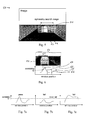
- Fig. 8 shows the processing flow of NCC for two image patches P1 and P2. First the mean and standard deviation is calculated for each patch. Then the patch values are normalized using mean and standard deviation. Finally, a matching score is computed.
- the summed normalized correlation is used for the correlation measure.
- the summed normalized correlation is disclosed e.g. in the document " A two-stage correlation method for stereoscopic depth estimation", Amsterdamcke, N. and Eggert, J. (2010), in Proceedings of the International Conference on Digital Image Computing: Techniques and Applications (DICTA), pages 227-234 , or in the document EP 2386998 A1 . These documents are hereby incorporated by reference.
- the summed normalized correlation is a cost function for image correlation computation. It is a two-stage filtering that performs a normalized cross-correlation (NCC) with a very small filter in the first stage and aggregates the resulting correlation coefficients in the second stage.
- NCC normalized cross-correlation
- SNCC normalized cross-correlation
- the image patches (A) are divided into subparts (B). As is depicted in the inset (B') at the upper left of Fig. 9 these subparts may also overlap. Furthermore, the two patches are subdivided in an analogous way, so that each subpart in one patch has a corresponding subpart in the other patch (C).
- each corresponding subpart pair is passed toward the NCC calculation (D).
- Each NCC box in Fig. 9 can be replaced by the scheme shown in Fig. 8 . This leads to local similarity scores for each subpart pair. These scores are integrated into a total matching score in a third step (E), which finally leads to the similarity evaluation (F).
- the correlation measure can be based on a known local mean and variance normalization together with the known methods sum of absolute difference (SAD) or sum of squared difference (SSD).
- SAD sum of absolute difference
- SSD sum of squared difference
- the sum of absolute difference (SAD) is e.g. an algorithm for measuring the similarity between image blocks. It works by taking the absolute difference between each pixel in the original block and the corresponding pixel in the block being used for comparison. These differences are summed to create a simple metric of block similarity.
- rank transform cost function for correlation is based on the idea of replacing each pixel intensity with its rank among a certain neighborhood. This removes most of the lighting changes that can occur between images.
- the actual rank transform is only a preprocessing of the images, which is usually followed by a further computation with sum of absolute difference (SAD) or sum of squared difference (SSD).
- the "census transform” cost function is an extension of the rank transform which does not replace the pixels with their rank but rather a binary fingerprint that encodes which pixels of the neighborhood are smaller than an anchor pixel.
- the matching cost here is the Hamming distance between two such finger prints.
- the symmetry search may also be performed in the frequency domain, e.g. via a phase only correlation (POC).
- the phase only correlation is used to compute horizontal shifts between the content of the symmetry window 61 and its vertical mirrored image.
- Both the content of the symmetry window 61 and its mirrored image are made up of pixels arrayed in a mesh-like pattern.
- pixel information patterns of all meshes are separately subjected to a Fourier transformation. Then, a phase-only processing is carried out on the Fourier transformation plane in order to determine a matching point between both the patterns.
- a find peaks step 42 is performed for finding peaks in the computed correlation curve 62. These peaks are potential candidates for the symmetry axis of the object 51. By sweeping a search window 63 over the correlation curve 62, all candidate peaks are indentified. A peak is found when the correlation at the center of the search window 63 is the maximum within the whole search window 63.
- the size of the search window 63 is a certain ratio of the region of interest 52. In the present embodiment it is half of the region of interest width. As a matter of fact, multiple peaks may be found in this step:
- Fig. 6 shows an embodiment with a correlation curve 62 having two peaks 64, 65.
- Each of these peaks 64, 65 is verified in the verify peaks step 43, which is illustrated in Figs. 7a, 7b and 7c .
- the verification is performed with the following two criteria.
- the correlation at the peak 64, 65 has to be greater than a threshold T.
- the segment of the correlation curve that contains the peak 64, 65 and is above the threshold is narrower than a certain ratio of the ROI width. In a particular embodiment, the ratio can be 1.5.
- Figs. 7a, 7b and 7c show some typical correlation curves to visualize the above criteria.
- the first criterion verifies that the confidence of a symmetry peak is high enough, and the second criterion is to remove peaks that are due to poor texture. Peaks that fail these criteria are removed from the list of peaks. Peaks are removed from the list of peaks preferably if they do not meet these two criteria. Alternatively, they are removed if only one of the two criteria is not fulfilled.
- Fig. 7a shows an embodiment with both criteria being fulfilled.
- the first criterion is not met because no peak is above the predetermined threshold T.
- the second criterion is not fulfilled.
- the lateral position of the object is not updated or corrected, but the lateral position 6 measured by the radar 2 is used instead.
- the following check consistency step 44 checks if peaks are consistent with the past positions of the object 51. To this end, the lateral positions of the peaks in an image are converted back to lateral positions in the radar coordinate system using the coordinate transformation module 12. Then the median of the lateral positions in the last time frames are computed and the lateral position of the peak closest to the median is determined. For example, the last five time frames can be used to compute the median. If the difference between the median and the closest lateral position is less than a threshold then the peak passes into the next step, otherwise the consistency of the lateral position of the peaks are processed further.
- Those remaining peaks are checked with the following criteria: the lateral position of the peak which is closest to the last lateral position updated by this module is determined, and it passes into the next step if their difference is less than a threshold. In case that the last position was not updated in this module or the difference is larger than a threshold, the lateral position of the object is not updated, but its radar position 6 is used instead.
- the stabilize peak step 45 is performed to avoid jitter in the lateral position.
- the stabilized lateral position in image coordinates is converted to the radar coordinate by the coordinate transformation module 12, and the lateral position 6 originally estimated by the radar is updated with the refined lateral position 25 in this module.
- the system 1 further comprises a Kalman filter module 13.
- a Kalman filter is well known in the art, and is e.g. described in Kalman, R. E. (1960). A new approach to linear filtering and prediction problems. Transactions of the ASME - Journal of Basic Engineering, 82(1):35-45 .
- the Kalman filter module 13 receives the object's lateral position with a flag indicating whether or not it has been updated in the lateral position improvement module 11. Since noise in the lateral position is expected to be lower when it is updated by the module as compared to the radar lateral position 6, the noise parameters of the Kalman Filter dynamically adapts to the flag or indicator of the source of lateral position.
Priority Applications (3)
| Application Number | Priority Date | Filing Date | Title |
|---|---|---|---|
| EP12159423.8A EP2639781A1 (fr) | 2012-03-14 | 2012-03-14 | Véhicule avec détection de position d'objet de trafic amélioré |
| JP2013027937A JP5689907B2 (ja) | 2012-03-14 | 2013-02-15 | 車両において通行物体位置検出を向上する方法 |
| US13/799,338 US9313462B2 (en) | 2012-03-14 | 2013-03-13 | Vehicle with improved traffic-object position detection using symmetric search |
Applications Claiming Priority (1)
| Application Number | Priority Date | Filing Date | Title |
|---|---|---|---|
| EP12159423.8A EP2639781A1 (fr) | 2012-03-14 | 2012-03-14 | Véhicule avec détection de position d'objet de trafic amélioré |
Publications (1)
| Publication Number | Publication Date |
|---|---|
| EP2639781A1 true EP2639781A1 (fr) | 2013-09-18 |
Family
ID=45928661
Family Applications (1)
| Application Number | Title | Priority Date | Filing Date |
|---|---|---|---|
| EP12159423.8A Withdrawn EP2639781A1 (fr) | 2012-03-14 | 2012-03-14 | Véhicule avec détection de position d'objet de trafic amélioré |
Country Status (3)
| Country | Link |
|---|---|
| US (1) | US9313462B2 (fr) |
| EP (1) | EP2639781A1 (fr) |
| JP (1) | JP5689907B2 (fr) |
Cited By (19)
| Publication number | Priority date | Publication date | Assignee | Title |
|---|---|---|---|---|
| DE102014118035A1 (de) | 2014-12-05 | 2016-06-09 | Valeo Schalter Und Sensoren Gmbh | Verfahren zum Erkennen einer Abschattung einer Sensoreinrichtung eines Kraftfahrzeugs durch ein Objekt, Recheneinrichtung, Fahrerassistenzsystem sowie Kraftfahrzeug |
| WO2016114885A1 (fr) * | 2015-01-16 | 2016-07-21 | Qualcomm Incorporated | Détection d'objet à l'aide de données d'emplacement et de représentations d'espace d'échelle de données d'image |
| FR3036204A1 (fr) * | 2015-05-11 | 2016-11-18 | Valeo Schalter & Sensoren Gmbh | Procede et systeme de compensation d'erreurs pour un systeme de detection d'objets embarque sur un vehicule automobile |
| EP3229041A1 (fr) * | 2016-03-30 | 2017-10-11 | Delphi Technologies, Inc. | Détection d'objet au moyen d'une zone de détection d'image définie par radar et vision |
| CN108001457A (zh) * | 2016-10-28 | 2018-05-08 | 德尔福技术公司 | 自动车辆传感器控制系统 |
| CN108604413A (zh) * | 2016-01-19 | 2018-09-28 | 日产自动车株式会社 | 显示装置的控制方法及显示装置 |
| US10126136B2 (en) | 2016-06-14 | 2018-11-13 | nuTonomy Inc. | Route planning for an autonomous vehicle |
| EP3415943A1 (fr) * | 2017-06-13 | 2018-12-19 | Veoneer Sweden AB | Estimation d'erreur pour un système de détection d'environnement de véhicule |
| CN109426802A (zh) * | 2017-08-22 | 2019-03-05 | 通用汽车环球科技运作有限责任公司 | 雷达和视觉传感器系统的融合 |
| US10309792B2 (en) | 2016-06-14 | 2019-06-04 | nuTonomy Inc. | Route planning for an autonomous vehicle |
| EP3493443A1 (fr) | 2013-12-06 | 2019-06-05 | Alcatel Lucent | Procédé et dispositif pour configurer dynamiquement soit une mécanisme de codage ou de retransmission comme protection contre des impulsions de bruit sur une ligne de communication |
| US10331129B2 (en) | 2016-10-20 | 2019-06-25 | nuTonomy Inc. | Identifying a stopping place for an autonomous vehicle |
| US10473470B2 (en) | 2016-10-20 | 2019-11-12 | nuTonomy Inc. | Identifying a stopping place for an autonomous vehicle |
| FR3087932A1 (fr) * | 2018-10-26 | 2020-05-01 | Psa Automobiles Sa | Procede de determination du caractere identique d’objets detectes par des capteurs differents dans l’environnement d’un vehicule automobile |
| US10681513B2 (en) | 2016-10-20 | 2020-06-09 | nuTonomy Inc. | Identifying a stopping place for an autonomous vehicle |
| US10857994B2 (en) | 2016-10-20 | 2020-12-08 | Motional Ad Llc | Identifying a stopping place for an autonomous vehicle |
| US11092446B2 (en) | 2016-06-14 | 2021-08-17 | Motional Ad Llc | Route planning for an autonomous vehicle |
| WO2022042806A1 (fr) * | 2020-08-25 | 2022-03-03 | Continental Automotive Gmbh | Procédé destiné à être mis en oeuvre par un système de détection pour un installation d'infrastructure routière et système de détection |
| RU2805133C2 (ru) * | 2019-01-21 | 2023-10-11 | Рено С.А.С | Способ определения оценки достоверности цели в окружающей среде транспортного средства |
Families Citing this family (43)
| Publication number | Priority date | Publication date | Assignee | Title |
|---|---|---|---|---|
| US20120229596A1 (en) * | 2007-03-16 | 2012-09-13 | Michael Kenneth Rose | Panoramic Imaging and Display System With Intelligent Driver's Viewer |
| US8957807B2 (en) * | 2011-12-14 | 2015-02-17 | Ford Global Technologies, Llc | Internal multi-axis G sensing used to align an automotive forward radar to the vehicle's thrust axis |
| US9746554B2 (en) * | 2013-04-09 | 2017-08-29 | Valeo Radar Systems, Inc. | Radar imaging system and related techniques |
| KR101417659B1 (ko) * | 2013-07-11 | 2014-07-09 | 현대자동차주식회사 | 차량 전방의 협로 검출 장치 및 그 방법 |
| JP5812061B2 (ja) * | 2013-08-22 | 2015-11-11 | 株式会社デンソー | 物標検出装置およびプログラム |
| KR20160103008A (ko) * | 2013-12-03 | 2016-08-31 | 뷰레이 테크놀로지스 인크. | 위상 상관을 이용한 비-강성 변형의 존재시에 의료 영상들의 단일- 및 다중-모달리티 정렬 |
| US10254395B2 (en) * | 2013-12-04 | 2019-04-09 | Trimble Inc. | System and methods for scanning with integrated radar detection and image capture |
| EP3060942B1 (fr) | 2013-12-06 | 2019-10-02 | Siemens Aktiengesellschaft | Procédé pour la détermination de la disposition d'au moins deux capteurs et réseaux de capteurs |
| KR101727162B1 (ko) * | 2014-02-27 | 2017-04-14 | 한국전자통신연구원 | 관제 서비스 제공 장치 및 그 방법 |
| DE102014003221A1 (de) * | 2014-03-05 | 2015-09-10 | Audi Ag | Verfahren zur maßstabskorrekten Skalierung einer Aufnahme eines Kamerasensors |
| JP6313617B2 (ja) * | 2014-03-17 | 2018-04-18 | スタンレー電気株式会社 | 距離画像生成装置、物体検出装置および物体検出方法 |
| EP3194211A4 (fr) * | 2014-08-04 | 2017-08-09 | Gentex Corporation | Système d'assistance au conducteur utilisant un capteur inertiel |
| JP6265149B2 (ja) * | 2014-08-27 | 2018-01-24 | 株式会社デンソー | 検出装置 |
| KR101692628B1 (ko) * | 2014-12-24 | 2017-01-04 | 한동대학교 산학협력단 | 관심영역을 이용하여 차량의 후방 좌우 옆 차선 영역을 감지하는 방법 및 이를 이용한 차량용 영상 모니터링 시스템 |
| US10302741B2 (en) * | 2015-04-02 | 2019-05-28 | Texas Instruments Incorporated | Method and apparatus for live-object detection |
| JP6320542B2 (ja) | 2015-05-23 | 2018-05-09 | エスゼット ディージェイアイ テクノロジー カンパニー リミテッドSz Dji Technology Co.,Ltd | 初期構成を有する複数のセンサを有する可動物体に対する1または複数の外部パラメータを推定する方法、システム、及びプログラム |
| EP3158293B1 (fr) * | 2015-05-23 | 2019-01-23 | SZ DJI Technology Co., Ltd. | Fusion de capteurs à l'aide de capteurs inertiels et d'images |
| US11378629B2 (en) | 2016-06-22 | 2022-07-05 | Viewray Technologies, Inc. | Magnetic resonance imaging |
| US11284811B2 (en) | 2016-06-22 | 2022-03-29 | Viewray Technologies, Inc. | Magnetic resonance volumetric imaging |
| US10571913B2 (en) * | 2016-08-05 | 2020-02-25 | Aptiv Technologies Limited | Operation-security system for an automated vehicle |
| JP6722066B2 (ja) * | 2016-08-29 | 2020-07-15 | 株式会社Soken | 周辺監視装置及び周辺監視方法 |
| KR20180041525A (ko) * | 2016-10-14 | 2018-04-24 | 주식회사 만도 | 차량의 물체 트래킹 시스템 및 그 제어 방법 |
| KR102488922B1 (ko) * | 2016-10-26 | 2023-01-17 | 주식회사 에이치엘클레무브 | 센서 융합을 통한 차량의 횡방향 거리 측정 장치 및 방법 |
| KR20180060784A (ko) * | 2016-11-29 | 2018-06-07 | 삼성전자주식회사 | 비정상 객체 판단 방법 및 장치 |
| KR101967812B1 (ko) * | 2017-02-17 | 2019-04-11 | 옴니센서(주) | 가중치 적용 칼만 필터를 이용한 레이더 신호 처리 장치 및 그를 이용한 표적 검출 시스템 |
| IT201700050502A1 (it) * | 2017-05-10 | 2018-11-10 | Ducati Motor Holding Spa | Motocicletta con dispositivo di rilevamento di un veicolo che sopraggiunge dal retro |
| JP6480504B2 (ja) | 2017-05-31 | 2019-03-13 | 本田技研工業株式会社 | 物標認識システム、物標認識方法、およびプログラム |
| KR102371616B1 (ko) * | 2017-11-07 | 2022-03-07 | 현대자동차주식회사 | 차량의 센서 데이터 연계 장치 및 방법 |
| CN109343049B (zh) * | 2017-11-10 | 2022-04-26 | 毫末智行科技有限公司 | 跟踪可移动目标的方法和装置 |
| US11041941B2 (en) * | 2018-02-26 | 2021-06-22 | Steradian Semiconductors Private Limited | Method and device for calibrating a radar object detection system |
| DE102018122092A1 (de) * | 2018-09-11 | 2020-03-12 | Valeo Schalter Und Sensoren Gmbh | Verfahren zum Bestimmen zumindest eines Positionsparameters eines Objekts in einer Umgebung eines Kraftfahrzeugs, Computerprogrammprodukt, Fahrerassistenzsystem und Kraftfahrzeug |
| US11835948B2 (en) | 2018-12-03 | 2023-12-05 | Motional Ad Llc | Systems and methods for improving vehicle operations using movable sensors |
| JP2020091672A (ja) * | 2018-12-06 | 2020-06-11 | ロベルト・ボッシュ・ゲゼルシャフト・ミト・ベシュレンクテル・ハフツングRobert Bosch Gmbh | 鞍乗型車両のライダー支援システムのための処理装置及び処理方法、鞍乗型車両のライダー支援システム、及び、鞍乗型車両 |
| US11630197B2 (en) * | 2019-01-04 | 2023-04-18 | Qualcomm Incorporated | Determining a motion state of a target object |
| JP6698188B2 (ja) * | 2019-02-07 | 2020-05-27 | 本田技研工業株式会社 | 物標認識システム、物標認識方法、およびプログラム |
| JP7196789B2 (ja) * | 2019-07-02 | 2022-12-27 | 株式会社デンソー | 車載センサ装置 |
| US11131776B2 (en) * | 2019-08-19 | 2021-09-28 | Gm Global Technology Operations, Llc | Method and apparatus for Kalman filter parameter selection using map data |
| CN110611791B (zh) * | 2019-08-26 | 2021-06-22 | 安徽四创电子股份有限公司 | 一种水域探测监控系统 |
| CN110646792B (zh) * | 2019-11-04 | 2022-04-12 | 中国人民解放军空军工程大学 | 一种基于观察哨数字望远镜的雷达搜索窗口设置方法 |
| CN111369541B (zh) * | 2020-03-06 | 2022-07-08 | 吉林大学 | 一种智能汽车恶劣天气条件下车辆检测方法 |
| US11418773B2 (en) * | 2020-04-21 | 2022-08-16 | Plato Systems, Inc. | Method and apparatus for camera calibration |
| CN111860161B (zh) * | 2020-06-16 | 2023-11-10 | 成都浩孚科技有限公司 | 一种目标遮挡检测方法 |
| CN114167404A (zh) * | 2020-09-11 | 2022-03-11 | 华为技术有限公司 | 目标跟踪方法及装置 |
Citations (4)
| Publication number | Priority date | Publication date | Assignee | Title |
|---|---|---|---|---|
| WO2003001472A1 (fr) * | 2001-06-23 | 2003-01-03 | Lucas Industries Limited | Systeme de localisation d'objets pour vehicule routier |
| US6590521B1 (en) | 1999-11-04 | 2003-07-08 | Honda Giken Gokyo Kabushiki Kaisha | Object recognition system |
| AT501882A1 (de) * | 2005-06-03 | 2006-12-15 | Advanced Comp Vision Gmbh Acv | Verfahren zum erkennen von gegenständen |
| EP2386998A1 (fr) | 2010-05-14 | 2011-11-16 | Honda Research Institute Europe GmbH | Procédé de corrélation en deux étapes pour recherche de correspondance |
Family Cites Families (33)
| Publication number | Priority date | Publication date | Assignee | Title |
|---|---|---|---|---|
| AU3325500A (en) * | 1999-03-24 | 2000-10-09 | Nikon Corporation | Position determining device, position determining method and exposure device, exposure method and alignment determining device, and alignment determining method |
| JP4308381B2 (ja) * | 1999-09-29 | 2009-08-05 | 富士通テン株式会社 | 周辺監視センサ |
| US6570840B1 (en) * | 2000-04-26 | 2003-05-27 | Optical Disc Corporation | Figure of merit in optical recording structures |
| DE10030258A1 (de) * | 2000-06-20 | 2002-01-03 | Daimler Chrysler Ag | Verfahren zur Abstandsregelung eines Fahrzeugs zu einem vorausfahrenden Fremdfahrzeug und Abstandsregelsystem |
| US6961449B2 (en) * | 2001-01-16 | 2005-11-01 | University Of Massachusetts Lowell | Method of correlation of images in biometric applications |
| US6842538B2 (en) * | 2001-03-23 | 2005-01-11 | Shih-Jong J. Lee | Automatic detection of alignment or registration marks |
| US7012952B2 (en) * | 2001-08-01 | 2006-03-14 | Qualcomm Incorporated | Method and apparatus for adjusting delay in systems with time-burst pilot and fractionally spaced equalizers |
| JP2003135445A (ja) * | 2001-10-31 | 2003-05-13 | Toshiba Corp | X線ct装置、x線ct装置アライメント方法、及びx線ct装置アライメントサービス提供システム |
| TW200301352A (en) * | 2001-12-05 | 2003-07-01 | Hamamatsu Photonics Kk | Light detection device, imaging device and device for depth capture |
| AU2002236414A1 (en) * | 2002-01-18 | 2003-07-30 | Kent Ridge Digital Labs | Method and apparatus for determining symmetry in 2d and 3d images |
| JP3985615B2 (ja) * | 2002-07-16 | 2007-10-03 | 日産自動車株式会社 | 前方車両追跡システムおよび前方車両追跡方法 |
| KR20040050569A (ko) * | 2002-12-10 | 2004-06-16 | 한국전자통신연구원 | 피두셜 마크의 중심 위치 측정방법 |
| JPWO2005008753A1 (ja) * | 2003-05-23 | 2006-11-16 | 株式会社ニコン | テンプレート作成方法とその装置、パターン検出方法、位置検出方法とその装置、露光方法とその装置、デバイス製造方法及びテンプレート作成プログラム |
| JP4162095B2 (ja) * | 2003-12-11 | 2008-10-08 | ストライダー ラブス,インコーポレイテッド | 遮蔽された部分の表面を対称性の算出により見込み復元するための技術 |
| US8064660B2 (en) * | 2004-02-27 | 2011-11-22 | National University Of Singapore | Method and system for detection of bone fractures |
| WO2006013635A1 (fr) * | 2004-08-03 | 2006-02-09 | Techno Dream 21 Co., Ltd. | Procédé de mesure de forme en trois dimensions et appareil correspondant |
| JP2007104171A (ja) * | 2005-10-03 | 2007-04-19 | Omron Corp | 前方監視装置 |
| JP2007163317A (ja) * | 2005-12-14 | 2007-06-28 | Fujitsu Ten Ltd | レーダー装置 |
| JP4595833B2 (ja) * | 2006-02-24 | 2010-12-08 | トヨタ自動車株式会社 | 物体検出装置 |
| US8160758B2 (en) * | 2006-05-22 | 2012-04-17 | Honeywell International Inc. | Methods and systems for radar aided aircraft positioning for approaches and landings |
| JP2008089402A (ja) * | 2006-10-02 | 2008-04-17 | Konica Minolta Holdings Inc | 情報処理システム、プログラムおよび情報処理方法 |
| CA2631004C (fr) * | 2007-05-09 | 2016-07-19 | Universite De Sherbrooke | Methodes de reconstruction d'images basees sur le systeme des matrices-blocs circulantes |
| US7666915B2 (en) * | 2007-09-24 | 2010-02-23 | Headwaters Technology Innovation, Llc | Highly dispersible carbon nanospheres in a polar solvent and methods for making same |
| US8284190B2 (en) * | 2008-06-25 | 2012-10-09 | Microsoft Corporation | Registration of street-level imagery to 3D building models |
| US8193967B2 (en) * | 2008-12-10 | 2012-06-05 | The United States Of America As Represented By The Secretary Of The Army | Method and system for forming very low noise imagery using pixel classification |
| US7796829B2 (en) * | 2008-12-10 | 2010-09-14 | The United States Of America As Represented By The Secretary Of The Army | Method and system for forming an image with enhanced contrast and/or reduced noise |
| JP5287392B2 (ja) * | 2009-03-17 | 2013-09-11 | トヨタ自動車株式会社 | 物体識別装置 |
| JP5229126B2 (ja) * | 2009-06-17 | 2013-07-03 | 日本電気株式会社 | 目標追尾処理器及びそれに用いる誤差共分散行列の補正方法 |
| DE112009005424B4 (de) * | 2009-12-08 | 2015-12-24 | Toyota Jidosha Kabushiki Kaisha | Objektdetektionsvorrichtung und Objektdetektionsverfahren |
| JP2011158409A (ja) * | 2010-02-03 | 2011-08-18 | Mitsubishi Electric Corp | 目標追尾装置及びコンピュータプログラム及び目標追尾方法 |
| US8933986B2 (en) * | 2010-05-28 | 2015-01-13 | Qualcomm Incorporated | North centered orientation tracking in uninformed environments |
| US8704887B2 (en) * | 2010-12-02 | 2014-04-22 | GM Global Technology Operations LLC | Multi-object appearance-enhanced fusion of camera and range sensor data |
| US8730091B2 (en) * | 2011-05-10 | 2014-05-20 | Raytheon Company | Target identification for a radar image |
-
2012
- 2012-03-14 EP EP12159423.8A patent/EP2639781A1/fr not_active Withdrawn
-
2013
- 2013-02-15 JP JP2013027937A patent/JP5689907B2/ja not_active Expired - Fee Related
- 2013-03-13 US US13/799,338 patent/US9313462B2/en active Active
Patent Citations (5)
| Publication number | Priority date | Publication date | Assignee | Title |
|---|---|---|---|---|
| US6590521B1 (en) | 1999-11-04 | 2003-07-08 | Honda Giken Gokyo Kabushiki Kaisha | Object recognition system |
| WO2003001472A1 (fr) * | 2001-06-23 | 2003-01-03 | Lucas Industries Limited | Systeme de localisation d'objets pour vehicule routier |
| US20040178945A1 (en) | 2001-06-23 | 2004-09-16 | Buchanan Alastair James | Object location system for a road vehicle |
| AT501882A1 (de) * | 2005-06-03 | 2006-12-15 | Advanced Comp Vision Gmbh Acv | Verfahren zum erkennen von gegenständen |
| EP2386998A1 (fr) | 2010-05-14 | 2011-11-16 | Honda Research Institute Europe GmbH | Procédé de corrélation en deux étapes pour recherche de correspondance |
Non-Patent Citations (3)
| Title |
|---|
| EINECKE, N.; EGGERT, J.: "A two-stage correlation method for stereoscopic depth estimation", PROCEEDINGS OF THE INTERNATIONAL CONFERENCE ON DIGITAL IMAGE COMPUTING: TECHNIQUES AND APPLICATIONS (DICTA, 2010, pages 227 - 234, XP031853178 |
| KALMAN, R. E.: "A new approach to linear filtering and prediction problems", TRANSACTIONS OF THE ASME - JOURNAL OF BASIC ENGINEERING, vol. 82, no. 1, 1960, pages 35 - 45, XP008039411 |
| ZABIH, R.; WOODFILL, J.: "Non- parametric local transforms for computing visual correspondence", PROCEEDINGS OF THIRD EUROPEAN CONFERENCE ON COMPUTER VISION (ECCV, 1994, pages 151 - 158, XP047289384, DOI: doi:10.1007/BFb0028345 |
Cited By (32)
| Publication number | Priority date | Publication date | Assignee | Title |
|---|---|---|---|---|
| EP3493443A1 (fr) | 2013-12-06 | 2019-06-05 | Alcatel Lucent | Procédé et dispositif pour configurer dynamiquement soit une mécanisme de codage ou de retransmission comme protection contre des impulsions de bruit sur une ligne de communication |
| DE102014118035B4 (de) | 2014-12-05 | 2022-11-17 | Valeo Schalter Und Sensoren Gmbh | Verfahren zum Erkennen einer Abschattung einer Sensoreinrichtung eines Kraftfahrzeugs durch ein Objekt, Recheneinrichtung, Fahrerassistenzsystem sowie Kraftfahrzeug |
| DE102014118035A1 (de) | 2014-12-05 | 2016-06-09 | Valeo Schalter Und Sensoren Gmbh | Verfahren zum Erkennen einer Abschattung einer Sensoreinrichtung eines Kraftfahrzeugs durch ein Objekt, Recheneinrichtung, Fahrerassistenzsystem sowie Kraftfahrzeug |
| US10908259B2 (en) | 2014-12-05 | 2021-02-02 | Valeo Schalter Und Sensoren Gmbh | Method for detecting a screening of a sensor device of a motor vehicle by an object, computing device, driver-assistance system and motor vehicle |
| WO2016114885A1 (fr) * | 2015-01-16 | 2016-07-21 | Qualcomm Incorporated | Détection d'objet à l'aide de données d'emplacement et de représentations d'espace d'échelle de données d'image |
| US10133947B2 (en) | 2015-01-16 | 2018-11-20 | Qualcomm Incorporated | Object detection using location data and scale space representations of image data |
| FR3036204A1 (fr) * | 2015-05-11 | 2016-11-18 | Valeo Schalter & Sensoren Gmbh | Procede et systeme de compensation d'erreurs pour un systeme de detection d'objets embarque sur un vehicule automobile |
| CN108604413A (zh) * | 2016-01-19 | 2018-09-28 | 日产自动车株式会社 | 显示装置的控制方法及显示装置 |
| CN108604413B (zh) * | 2016-01-19 | 2020-06-16 | 日产自动车株式会社 | 显示装置的控制方法及显示装置 |
| US10522041B2 (en) | 2016-01-19 | 2019-12-31 | Nissan Motor Co., Ltd. | Display device control method and display device |
| EP3407325A4 (fr) * | 2016-01-19 | 2019-07-03 | Nissan Motor Co., Ltd. | Procédé de commande de dispositif d'affichage et dispositif d'affichage |
| EP3229041A1 (fr) * | 2016-03-30 | 2017-10-11 | Delphi Technologies, Inc. | Détection d'objet au moyen d'une zone de détection d'image définie par radar et vision |
| US11022449B2 (en) | 2016-06-14 | 2021-06-01 | Motional Ad Llc | Route planning for an autonomous vehicle |
| US10309792B2 (en) | 2016-06-14 | 2019-06-04 | nuTonomy Inc. | Route planning for an autonomous vehicle |
| US11092446B2 (en) | 2016-06-14 | 2021-08-17 | Motional Ad Llc | Route planning for an autonomous vehicle |
| US11022450B2 (en) | 2016-06-14 | 2021-06-01 | Motional Ad Llc | Route planning for an autonomous vehicle |
| US10126136B2 (en) | 2016-06-14 | 2018-11-13 | nuTonomy Inc. | Route planning for an autonomous vehicle |
| US10857994B2 (en) | 2016-10-20 | 2020-12-08 | Motional Ad Llc | Identifying a stopping place for an autonomous vehicle |
| US10331129B2 (en) | 2016-10-20 | 2019-06-25 | nuTonomy Inc. | Identifying a stopping place for an autonomous vehicle |
| US10681513B2 (en) | 2016-10-20 | 2020-06-09 | nuTonomy Inc. | Identifying a stopping place for an autonomous vehicle |
| US11711681B2 (en) | 2016-10-20 | 2023-07-25 | Motional Ad Llc | Identifying a stopping place for an autonomous vehicle |
| US10473470B2 (en) | 2016-10-20 | 2019-11-12 | nuTonomy Inc. | Identifying a stopping place for an autonomous vehicle |
| CN108001457A (zh) * | 2016-10-28 | 2018-05-08 | 德尔福技术公司 | 自动车辆传感器控制系统 |
| CN108001457B (zh) * | 2016-10-28 | 2022-06-10 | 动态Ad有限责任公司 | 自动车辆传感器控制系统 |
| EP3318893A1 (fr) * | 2016-10-28 | 2018-05-09 | Delphi Technologies, Inc. | Système de commande de capteur de véhicule automatisé |
| WO2018228869A1 (fr) * | 2017-06-13 | 2018-12-20 | Veoneer Sweden Ab | Estimation d'erreur pour un système de détection d'environnement de véhicule |
| US11327154B2 (en) * | 2017-06-13 | 2022-05-10 | Veoneer Sweden Ab | Error estimation for a vehicle environment detection system |
| EP3415943A1 (fr) * | 2017-06-13 | 2018-12-19 | Veoneer Sweden AB | Estimation d'erreur pour un système de détection d'environnement de véhicule |
| CN109426802A (zh) * | 2017-08-22 | 2019-03-05 | 通用汽车环球科技运作有限责任公司 | 雷达和视觉传感器系统的融合 |
| FR3087932A1 (fr) * | 2018-10-26 | 2020-05-01 | Psa Automobiles Sa | Procede de determination du caractere identique d’objets detectes par des capteurs differents dans l’environnement d’un vehicule automobile |
| RU2805133C2 (ru) * | 2019-01-21 | 2023-10-11 | Рено С.А.С | Способ определения оценки достоверности цели в окружающей среде транспортного средства |
| WO2022042806A1 (fr) * | 2020-08-25 | 2022-03-03 | Continental Automotive Gmbh | Procédé destiné à être mis en oeuvre par un système de détection pour un installation d'infrastructure routière et système de détection |
Also Published As
| Publication number | Publication date |
|---|---|
| JP2013190421A (ja) | 2013-09-26 |
| JP5689907B2 (ja) | 2015-03-25 |
| US20130335569A1 (en) | 2013-12-19 |
| US9313462B2 (en) | 2016-04-12 |
Similar Documents
| Publication | Publication Date | Title |
|---|---|---|
| US9313462B2 (en) | Vehicle with improved traffic-object position detection using symmetric search | |
| US11348266B2 (en) | Estimating distance to an object using a sequence of images recorded by a monocular camera | |
| US9846812B2 (en) | Image recognition system for a vehicle and corresponding method | |
| US11620837B2 (en) | Systems and methods for augmenting upright object detection | |
| US9824586B2 (en) | Moving object recognition systems, moving object recognition programs, and moving object recognition methods | |
| US10074021B2 (en) | Object detection apparatus, object detection method, and program | |
| JP4246766B2 (ja) | 車両から対象物を位置測定して追跡する方法および装置 | |
| JP5145585B2 (ja) | 物標検出装置 | |
| JP2007255979A (ja) | 物体検出方法および物体検出装置 | |
| EP3282389A1 (fr) | Appareil de traitement d'image, appareil de capture d'image, système de commande d'appareil de corps mobile, procédé de traitement d'image, et programme | |
| JP4052291B2 (ja) | 車両用画像処理装置 | |
| Romdhane et al. | A generic obstacle detection method for collision avoidance | |
| JP5256482B2 (ja) | 測距装置 | |
| JP2009186228A (ja) | 3次元計測装置 | |
| WO2020036039A1 (fr) | Dispositif de caméra stéréo | |
| EP3825648A1 (fr) | Dispositif de détection d'objet | |
| CN110488320A (zh) | 一种利用立体视觉检测车辆距离的方法 | |
| JP4381394B2 (ja) | 障害物検知装置及びその方法 |
Legal Events
| Date | Code | Title | Description |
|---|---|---|---|
| PUAI | Public reference made under article 153(3) epc to a published international application that has entered the european phase |
Free format text: ORIGINAL CODE: 0009012 |
|
| 17P | Request for examination filed |
Effective date: 20130128 |
|
| AK | Designated contracting states |
Kind code of ref document: A1 Designated state(s): AL AT BE BG CH CY CZ DE DK EE ES FI FR GB GR HR HU IE IS IT LI LT LU LV MC MK MT NL NO PL PT RO RS SE SI SK SM TR |
|
| AX | Request for extension of the european patent |
Extension state: BA ME |
|
| STAA | Information on the status of an ep patent application or granted ep patent |
Free format text: STATUS: REQUEST FOR EXAMINATION WAS MADE |
|
| STAA | Information on the status of an ep patent application or granted ep patent |
Free format text: STATUS: THE APPLICATION IS DEEMED TO BE WITHDRAWN |
|
| 18D | Application deemed to be withdrawn |
Effective date: 20171003 |