EP2639684A1 - Object display device and object display method - Google Patents
Object display device and object display method Download PDFInfo
- Publication number
- EP2639684A1 EP2639684A1 EP11839897.3A EP11839897A EP2639684A1 EP 2639684 A1 EP2639684 A1 EP 2639684A1 EP 11839897 A EP11839897 A EP 11839897A EP 2639684 A1 EP2639684 A1 EP 2639684A1
- Authority
- EP
- European Patent Office
- Prior art keywords
- display
- marker
- image
- real space
- virtual object
- Prior art date
- Legal status (The legal status is an assumption and is not a legal conclusion. Google has not performed a legal analysis and makes no representation as to the accuracy of the status listed.)
- Withdrawn
Links
Images





Classifications
-
- G—PHYSICS
- G06—COMPUTING OR CALCULATING; COUNTING
- G06T—IMAGE DATA PROCESSING OR GENERATION, IN GENERAL
- G06T11/00—Two-dimensional [2D] image generation
- G06T11/60—Creating or editing images; Combining images with text
-
- G—PHYSICS
- G06—COMPUTING OR CALCULATING; COUNTING
- G06F—ELECTRIC DIGITAL DATA PROCESSING
- G06F3/00—Input arrangements for transferring data to be processed into a form capable of being handled by the computer; Output arrangements for transferring data from processing unit to output unit, e.g. interface arrangements
- G06F3/01—Input arrangements or combined input and output arrangements for interaction between user and computer
- G06F3/048—Interaction techniques based on graphical user interfaces [GUI]
- G06F3/0481—Interaction techniques based on graphical user interfaces [GUI] based on specific properties of the displayed interaction object or a metaphor-based environment, e.g. interaction with desktop elements like windows or icons, or assisted by a cursor's changing behaviour or appearance
- G06F3/04815—Interaction with a metaphor-based environment or interaction object displayed as three-dimensional [3D], e.g. changing the user viewpoint with respect to the environment or object
-
- G—PHYSICS
- G06—COMPUTING OR CALCULATING; COUNTING
- G06T—IMAGE DATA PROCESSING OR GENERATION, IN GENERAL
- G06T11/00—Two-dimensional [2D] image generation
-
- G—PHYSICS
- G06—COMPUTING OR CALCULATING; COUNTING
- G06T—IMAGE DATA PROCESSING OR GENERATION, IN GENERAL
- G06T19/00—Manipulating three-dimensional [3D] models or images for computer graphics
- G06T19/006—Mixed reality
-
- G—PHYSICS
- G06—COMPUTING OR CALCULATING; COUNTING
- G06V—IMAGE OR VIDEO RECOGNITION OR UNDERSTANDING
- G06V10/00—Arrangements for image or video recognition or understanding
- G06V10/20—Image preprocessing
- G06V10/24—Aligning, centring, orientation detection or correction of the image
- G06V10/245—Aligning, centring, orientation detection or correction of the image by locating a pattern; Special marks for positioning
-
- G—PHYSICS
- G06—COMPUTING OR CALCULATING; COUNTING
- G06V—IMAGE OR VIDEO RECOGNITION OR UNDERSTANDING
- G06V20/00—Scenes; Scene-specific elements
- G06V20/20—Scenes; Scene-specific elements in augmented reality scenes
-
- G—PHYSICS
- G06—COMPUTING OR CALCULATING; COUNTING
- G06V—IMAGE OR VIDEO RECOGNITION OR UNDERSTANDING
- G06V10/00—Arrangements for image or video recognition or understanding
- G06V10/20—Image preprocessing
- G06V10/24—Aligning, centring, orientation detection or correction of the image
- G06V10/247—Aligning, centring, orientation detection or correction of the image by affine transforms, e.g. correction due to perspective effects; Quadrilaterals, e.g. trapezoids
Definitions
- the present invention relates to an object display device and an object display method.
- a technique in which a predetermined marker is detected from an image in real space acquired by the camera of a mobile terminal, and a virtual object associated with the marker is overlaid on the image in real space and displayed on a display.
- a terminal device is also known which estimates a change in spatial positional relationship between an image capturing unit and an object to be captured, from temporally different images, and performs control, for example, on scrolling on a display based on the change (see, for example, Patent Literature 1).
- Patent Literature 1 Japanese Patent Application Laid-Open Publication No. 2010-67090
- the technique of displaying a virtual object overlaid on an image in real space based on a marker detected from the image in real space captured by a camera cannot display the virtual object if the marker is not detected for some reason.
- the marker although existing in a shooting range, is not detected in some cases due to various reasons such as the positional relationship between the camera and the marker, and the shooting conditions such as brightness.
- An object of the present invention is to provide an object display device and an object display method capable of displaying a virtual object even when a marker in real space is not detected for some reason.
- an object display device detects a predetermined marker from an image in real space acquired by image capturing means and overlays a virtual object associated with the marker on the image in real space to display the overlaid virtual object on display means.
- the object display device includes display complementing means for, in the case that the marker is not detected, acquiring a change in the image in real space displayed on the display means between the past when the marker was detected and the present, and display decision means for deciding a display position and display manner of the virtual object based on the change in the image in real space displayed on the display means and acquired by the display complementing means.
- the display means displays the virtual object overlaid on the image in real space based on the display position and display manner of the virtual object that are decided by the display decision means.
- an object display method is performed in an object display device for detecting a predetermined marker from an image in real space acquired by image capturing means and for overlaying a virtual object associated with the marker on the image in real space to display the overlaid virtual object on display means.
- the object display method includes a display complementing step of, in the case that the marker is not detected, acquiring a change in the image in real space displayed on the display means between the past when the marker was detected and the present, a display decision step of deciding a display position and display manner of the virtual object based on the change in the image in real space displayed on the display means and acquired in the display complementing step, and a display step of displaying the virtual object overlaid on the image in real space based on the display position and display manner of the virtual object that are decided in the display decision step.
- the object display device and the object display method in the case that a marker is not detected at present, a change in an image in real space displayed on the display means between the past when the marker was detected and the present is acquired. Since a virtual object is displayed based on the position and shape of the marker in the image in real space, the display position and display manner of the virtual object are also to be changed in accordance with a change in the image in real space.
- the display position and display manner of the virtual object at present can therefore also be decided from the display position and display manner of the virtual object in the past, based on the change in the image in real space between the past and the present. Accordingly, the virtual object can be displayed even when the marker in real space is not detected for some reason.
- the display complementing means may include particular shape recognition means for extracting a particular shape from the image in real space and recognizing a change in the shape and position of the particular shape between the past when the marker was detected and the present.
- a change in the image in real space displayed on the display means may be acquired based on the change in the shape and position of the particular shape that is recognized by the particular shape recognition means.
- a change in the image in real space displayed on the display means is acquired based on a change in the shape and position of the particular shape extracted from the image in real space.
- the change in the shape and position of the particular shape is extracted from the image in real space in a similar manner as with the marker for deciding the display position and display manner of the virtual object, so that a change in the image in real space displayed on the display means is acquired accurately. Accordingly, the display position and display manner at present can be decided accurately based on the display position and display manner of the virtual object in the past.
- the particular shape for acquiring a change in the image in real space displayed on the display means may be a shape of a predetermined substance. In this case, a change in the image in real space displayed on the display means can be acquired reliably.
- the particular shape for acquiring a change in the image in real space displayed on the display means may be at least one of a predetermined graphic and line, and a certain region having a single color. In this case, the probability of extraction of the particular shape by the particular shape recognition means is improved.
- the display complementing means may include terminal attitude sensing means for sensing a change in a position and shooting direction of the object display device.
- the display decision means may decide the display position and display manner of the virtual object based on the change in the position and shooting direction of the object display device that is recognized by the terminal attitude sensing means.
- the display position and display manner of the virtual object are decided based on a change in the position and shooting direction of the object display device, so that the virtual object can be displayed even when the particular shape is not detected from the image in real space.
- the display decision means may estimate a position and shape of the marker in the image in real space displayed on the display means based on the change in the image in real space displayed on the display means, and may decide the display position and display manner of the virtual object based on the estimated position and shape of the marker.
- the position and shape of the marker in real space which serves as a basis for deciding the display position and display manner of the virtual object are estimated based on the change in the image in real space displayed on the display means, so that the display position and display manner of the virtual object at present can be decided appropriately.
- the position of a mobile terminal can be specified accurately and reliably.
- Fig. 1 is a block diagram showing a functional configuration of an object display device 1.
- the object display device 1 in the present embodiment is a device for detecting a predetermined marker from an image in real space acquired by image capturing means and overlays a virtual object associated with the marker on the image in real space to display the overlaid virtual object on display means.
- the marker is a predetermined sign present in real space.
- the object display device 1 stores data of virtual objects in advance, the data which is to be displayed in association with markers.
- the object display device 1 decides the display position and display manner of a virtual object based on the shape (deformation) and size of the marker, overlays the virtual object on the image in real space in accordance with the decided display position and display manner, and allows the overlaid virtual object to appear on the display.
- the object display device 1 may acquire data of the virtual object via communication.
- the virtual object is overlaid on an image in real space and displayed, thereby providing a variety of information to the user of the object display device 1.
- the object display device 1 functionally includes a camera 2 (image capturing means), an image acquisition unit 3, a marker recognition unit 4, a marker database 5, a display decision unit 6 (display decision means), an object database 7, a display unit 8 (display means), and a display complementing unit 9 (display complementing means).
- Fig. 2 is a hardware configuration diagram of the object display device 1.
- the object display device 1 is physically configured as a computer system mainly including a CPU 101, a RAM 102 and a ROM 103 as main storages, a communication module 104 that is a data transmission/reception device, an auxiliary storage device 105 such as a hard disk or a flash memory, an input device 106 such as a keyboard as an input device, and an output device 107 such as a display.
- a computer system mainly including a CPU 101, a RAM 102 and a ROM 103 as main storages, a communication module 104 that is a data transmission/reception device, an auxiliary storage device 105 such as a hard disk or a flash memory, an input device 106 such as a keyboard as an input device, and an output device 107 such as a display.
- Each function shown in Fig. 1 is implemented by reading predetermined computer software on the hardware such as the CPU 101 and the RAM 102 shown in Fig.
- the camera 2 is image capturing means for capturing an image in real space.
- the camera 2 sends the captured image in real space to the image acquisition unit 3.
- the image in real space includes still images and motion images.
- the image acquisition unit 3 is a unit that acquires an image in real space captured by the camera 2.
- the image acquisition unit 3 sends the acquired image in real space to the marker recognition unit 4 and the display complementing unit 9.
- the marker recognition unit 4 is a unit that recognizes a marker from an image in real space based on image data of the marker registered in the marker database 5.
- the marker is recognized, for example, by an image processing technique such as pattern matching known to those skilled in the art. More specifically, the marker recognition unit 4 extracts a marker from an image in real space and additionally recognizes the position and shape of the marker in the image in real space.
- the shape of the marker in the image in real space has a deformation in accordance with the positional relationship between the camera 2 and the marker, so that the orientation of the marker in the image in real space can be determined based on the shape of the marker.
- the marker recognition unit 4 sends information identifying the recognized marker and information about the position and shape of the marker in the image in real space to the display complementing unit 9 and the display decision unit 6.
- Fig. 3 is a diagram showing an example in which the marker recognition unit 4 cannot recognize a marker from an image in real space.
- Fig. 3(a) shows an example of an image f that appears on the display unit 8 when the positional relationship between the object display device 1 and a marker M is as shown in a schematic diagram in Fig. 3(b) .
- the marker M in the present embodiment is a sign in which a letter "i" of the alphabet is represented on a plane.
- the object display device 1 captures an image of the marker M from obliquely upward of the marker M, so that the marker recognition unit 4 can recognize the marker M from the image f.
- the display unit 8 overlays a virtual object O associated with the marker M on the image in real space and displays the overlaid virtual object O.
- Fig. 3(c) is an example of the image f that appears on the display unit 8 when the positional relationship between the object display device 1 and the marker M is as shown in a schematic diagram in Fig. 3(d) .
- the angle that the shooting direction for the object display device 1 to capture the image of the marker M forms with the upper surface of the marker M is small, so that, as shown in Fig. 3(c) , the degree of deformation of the shape of the marker M in the image f captured by the camera 2 and the image acquisition unit 3 is greater than that in Fig. 3(a) .
- the marker recognition unit 4 cannot recognize the marker M from the image f in real space. In this case, as shown in Fig. 3(c) , the display unit 8 does not overlay and display the virtual object O.
- Examples of possible cases where the marker recognition unit 4 cannot recognize a marker from an image in real space include, in addition to the case where the degree of deformation of the shape of the marker M is great as shown in Figs. 3(c) and (d) , a case where blown-out highlights occur due to flashing light and a case where the quantity of light for image capturing is insufficient.
- the marker database 5 is a database storing data of markers. Data of markers is more specifically image data of markers.
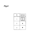
- Fig. 4 is a diagram showing a configuration of the marker database 5 and an example of data stored therein. As shown in Fig. 4 , the marker database 5 stores the data of markers associated with respective IDs identifying the markers.
- the display decision unit 6 extracts the data of a virtual object associated with the marker from the object database, based on the information identifying the marker that is sent from the marker recognition unit 4, and decides the display position and display manner of the virtual object in the image displayed on the display unit, based on the information about the position and shape of the marker that is sent from the marker recognition unit 4.
- the display position and display manner of the virtual object are defined based on the relative positional relationship to the marker associated with the virtual object.
- the positional relationship between the virtual object and the marker is stored as an offset in the object database 7 as described later.
- the data of the offset includes, for example, information indicating the relative position of the virtual object with reference to the position of the marker, and information about the orientation of the virtual object when displayed.
- the display decision unit 6 sends the information about the display position and display manner of the virtual object (including the information about the orientation) and the image data of the virtual object to the display unit 8.
- the display decision unit 6 acquires a change in the image in real space displayed on the display unit 8 between the past when the marker was detected and the present from the display complementing unit 9, and decides the display position and display manner of the virtual object in the image displayed on the display unit, based on the acquired change in the image in real space.
- the details of processing of deciding the display position and display manner of a virtual object in the case where a marker is not detected will be described later.
- the object database 7 is a database storing data concerning virtual objects.
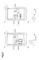
- Fig. 5 is a diagram showing a confguration of the object database 7 and an example of data stored therein.
- the object database 7 stores object data, associated markers, and offsets which are associated with respective object IDs identifying virtual objects.
- the object data is image data of a virtual object.
- the associated marker is an ID of a marker displayed in associated with the virtual object.
- the offset is data showing the positional relation to the marker when the virtual object overlaid on an image in real space is displayed.
- the display unit 8 is a unit that displays a virtual object overlaid on an image in real space based on the display position and display manner of the virtual object that are decided by the display decision unit 6.
- the display unit 8 is configured, for example, with a device such as a display.
- the display complementing unit 9 is a unit that acquires a change in the image in real space displayed on the display unit 8 between the past when a marker was detected and the present, in the case where the marker is not detected.
- the display complementing unit 9 includes a particular shape recognition unit 91 (particular shape recognition means), a sensor 92, and a terminal attitude sensing unit 93 (terminal attitude sensing means).
- the particular shape recognition unit 91 extracts a predetermined particular shape from an image in real space and recognizes a change in the shape and position of the particular shape between the past when the marker was detected and the present. More specifically, the particular shape recognition unit 91 stores the shape and position of the particular shape in the past when the marker was detected, into a predetermined memory, and, if the marker is not recognized at present, compares the shape and position of the particular shape acquired from the image in real space at present with the shape and position of the particular shape in the immediate past when the marker was detected, thereby recognizing the change therebetween.
- the display complementing unit 9 then acquires a change in the image in real space displayed on the display unit 8 based on the change in the shape and position of the particular shape that is recognized by the particular shape recognition unit 91, and sends information about the acquired change in the image in real space to the display decision unit 6.
- FIG. 6 a process of displaying an overlaid virtual object based on the extracted particular shape is described in details.
- Fig. 6(a) shows an example of an image f 1 that appears on the display unit 8 when the positional relationship between the object display device 1 and the marker M is as shown in a schematic diagram in Fig. 6(b) .
- the object display device 1 captures an image of the marker M from obliquely upward of the marker M.
- the angle that the shooting direction for capturing an image of the marker M from the object display device 1 forms with the upper surface of the marker M is large, so that the marker recognition unit 4 can recognize the marker M 1 from the image f 1 in the example shown in Fig. 6(a) .
- the display decision unit 6 extracts the virtual object O associated with the marker M recognized by the marker recognition unit 4 from the object database 7, decides the display position and display manner of the virtual object O based on the position and shape of the marker M 1 , and allows the display unit 8 to display the overlaid virtual object O 1 associated with the marker M 1 .
- Fig. 6(c) shows an example of the image f 1 that appears on the display unit 8 when the positional relationship between the object display device 1 and the marker M is as shown in a schematic diagram in Fig. 6(d) .
- the angle that the shooting direction for capturing an image of the marker M from the object display device 1 forms with the upper surface of the marker M is small, so that, as shown in Fig. 6(c) , the degree of deformation of the shape of the marker M 2 in an image F 2 displayed on the display unit 8 is greater than in Fig. 6(a) .
- the marker recognition unit 4 cannot recognize the marker M 2 . In this case, the marker recognition unit 4 sends information indicating that the marker is not recognized to the display complementing unit 9 and the display decision unit 6.
- the particular shape recognition unit 91 of the display complementing unit 9 When acquiring the information indicating that the marker is not recognized, the particular shape recognition unit 91 of the display complementing unit 9 extracts a particular shape S from the image f and recognizes a change in the shape and position between the particular shape S 1 in the image f 1 ( Fig. 6(a) ) in the past when the marker was detected and the particular shape S 2 in the image f 2 at present.
- the display complementing unit 9 sends the change in the shape and position of the particular shape S that is recognized by the particular shape recognition unit 91, as information about a change in the image in real space, to the display decision unit 6.
- the display decision unit 6 estimates the position and shape of the marker M 2 in the image f 2 at present based on the information about a change in the image in real space that is sent from the display complementing unit 9, as well as the position and shape of the marker M 1 in the image f 1 in the past when the marker M was detected.
- the display decision unit 6 decides the display position and display manner of the virtual object O 2 based on the estimated position and shape of the marker M 2 . More specifically, the display decision unit 6 estimates a relative change in the position and shape of the marker M between the images f 1 and f 2 based on a relative change in the position and shape between the particular shape S 1 in the image f 1 in the past and the particular shape S 2 in the image f 2 at present.
- the particular shape recognition unit 91 extracts the shape of a vase as a particular shape S.
- the target recognized as a particular shape S is not limited to the shape of such an object.
- the particular shape S may be the shape of a predetermined substance. Any substance that can be recognized by an image recognition technique known to those skilled in the art can be employed. Predetermined substances such as a logotype, a sign, a face, and a table can be employed.
- the particular shape S may be at least one of a predetermined graphic and line, and a certain region having a single color. Examples of such a particular shape S include a quadrature, a vertical line and a horizontal line, and a grid pattern formed with horizontal lines and vertical lines that are present in the image.
- data about the particular shape S may be stored in advance in predetermined storage means in the object display device 1.
- data about the particular shape S may not be retained in advance in storage means.
- the particular shape recognition unit 91 carries out a determination process as to whether a particular shape for acquiring a change in the image in real space can be extracted from the image acquired by the image acquisition unit 3, prior to the process of recognizing a change in the shape and position of the particular shape S.
- a process of overlaying a virtual object based on learning information acquired from changes of the particular shape and the shape of the marker will be described as a variation to the process described with reference to Fig. 6 .
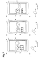
- Fig. 7(a) shows an example of the image f that appears on the display unit 8 when the positional relationship between the object display device 1 and the marker M is as shown in a schematic diagram in Fig. 7(b) .
- the object display device 1 captures an image of the marker M from obliquely upward of the marker M.
- the angle that the shooting direction for capturing an image of the marker M from the object display device 1 forms with the upper surface of the marker M is large, so that the marker recognition unit 4 can recognize the marker M from the image f in the example shown in Fig. 7(a) .
- the display decision unit 6 extracts the virtual object O associated with the marker M recognized by the marker recognition unit 4 from the object database 7, decides the display position and display manner of the virtual object O based on the position and shape of the marker M, and allows the display unit 8 to display the overlaid virtual object O associated with the marker M.
- Fig. 7(c) shows an example of the image f that appears on the display unit 8 when the positional relationship between the object display device 1 and the marker M is as shown in a schematic diagram in Fig. 7(d) .
- the angle that the shooting direction for the object display device 1 to capture an image of the marker M forms with the upper surface of the marker M is slightly smaller than that in Fig. 7(b) , so that, as shown in Fig. 7(c) , the degree of deformation of the shape of the marker M in the image f captured by the camera 2 and the image acquisition unit 3 is greater than in Fig. 7(a) .
- the display decision unit 6 decides the display position and display manner of the virtual object O based on the recognized marker M and allows the display unit 8 to display the overlaid virtual object O based on the decided display position and display manner.
- the marker recognition unit 4 acquires a change in the position and shape of the marker M during transition of display from the image f shown in Fig. 7(a) to the image f shown in Fig. 7(c) and sends information about the acquired change in the position and shape of the marker M to the display decision unit 6.
- the particular shape recognition unit 91 extracts and recognizes a particular shape B from the image f shown in Figs. 7(a) and (c) as an object shaped like a rectangular parallelepiped.
- the particular shape recognition unit 91 acquires a change in the position and shape of the particular shape B during transition of display from the image f shown in Fig. 7(a) to the image f shown in Fig. 7(c) and sends information about the acquired change in the position and shape of the particular shape B to the display decision unit 6.
- the display decision unit 6 acquires the information about the change in the position and shape of the marker M during transition of display from the image f shown in Fig. 7(a) to the image f shown in Fig. 7(c) from the marker recognition unit 4 and also acquires the information about the change in the position and shape of the particular shape B from the particular shape recognition unit 91.
- the display decision unit 6 then acquires the change in the position and shape of the marker M corresponding to the change in the position and shape of the particular shape B as learning information and stores the acquired learning information into a predetermined memory.
- the display decision unit 6 can estimate the position and shape of the marker M based on the learning information about the respective positions and shapes of the particular shape B and the marker M.
- the particular shape recognition unit 91 can recognize the particular shape B. The particular shape recognition unit 91 thus sends the position and shape of the particular shape B in the image f shown in Fig. 7(e) to the display decision unit 6.
- the display decision unit 6 estimates the position and shape of the marker M in Fig. 7(e) based on the position and shape of the particular shape B in Fig. 7(e) and the learning information about the respective positions and shapes of the particular shape B and the marker M.
- the display decision unit 6 decides the display position and display manner of the virtual object O based on the estimated position and shape of the marker M and allows the display unit 8 to display the virtual object O.
- the terminal attitude sensing unit 93 senses a change in the position and shooting direction of the object display device 1 based on a variety of information acquired from the sensor 92.
- the sensor 92 include sensors such as an accelerometer sensor and a geomagnetic sensor. Information about acceleration and the direction of geomagnetism acquired by those sensors is sent to the terminal attitude sensing unit 93.
- the display complementing unit 9 cannot acquire a change in the image displayed on the display unit 8
- the display decision unit 6 decides the display position and display manner of the virtual object based on the change in the position and shooting direction of the object display device 1 that is recognized by the terminal attitude sensing unit 93.
- Fig. 8 is a diagram showing an example of a table in which attitude data, a marker position, and an estimated marker shape are associated for each frame in the image displayed on the display unit 8.
- the frame No. in Fig. 8 is data identifying a frame.
- the attitude data (orientation) is data indicating the orientation of the object display device 1 at the point of time when the image of the corresponding frame is acquired.
- the attitude data (orientation) "D 0 " at the point of time when the image of the frame No. "100" is acquired is set as an initial state, and differential values from the data "D 0 " indicating the orientation are stored as "D 1 " and "D 2 ".
- the attitude data (orientation) can be represented, for example, by the rotation angle with respect to each axis in a predetermined three-dimensional coordinate system.
- the attitude data (position) is data indicating the position of the object display device 1 at the point of time when the image of the corresponding frame is acquired.
- the attitude data (position) at the point of time when the image of the frame No. "100" is acquired is set as an initial state, and differential values from the data "P 0 " indicating the orientation are stored as "P 1 " and "P 2 ".
- the terminal attitude sensing unit 93 sends the attitude data (orientation) and the attitude data (position) to the display decision unit 6.
- the attitude data (position) can be represented, for example, by coordinate values in a predetermined three-dimensional coordinate system.
- the marker position in the table shown in Fig. 8 is data indicating the display position of the marker at the point of time when the image of the corresponding frame is acquired.
- the marker position is represented, for example, by a predetermine coordinate system set in the display region of the display unit 8.
- the estimated marker shape is the marker shape displayed on the display unit 8 that is estimated by the display decision unit 6.
- the display decision unit 6 estimates the marker position based on the attitude data (orientation) and the attitude data (position). Specifically, the display decision unit 6 can estimate the marker position "M 1 " based on the attitude data (orientation) "D 1 " and the attitude data (position) "P 1 " as well as the marker position "M 0 ". Similarly, the display decision unit 6 can estimate the marker position "M 2 " based on the attitude data (orientation) "D 2 " and the attitude data (position) "P 2 " as well as the marker position "M 1 ".
- the display decision unit 6 can calculate the deformation of the shape of the marker displayed on the display unit 8 based on the attitude data (orientation) and the attitude data (position) and can estimate the estimated marker shape.
- the display decision unit 6 can determine whether a marker exists in a range of angle of view of the display unit 8 by estimating the marker position shown in the table in Fig. 8 when the marker recognition unit 4 cannot recognize the marker. This determination process is implemented, for example, by determining whether the coordinate values of the marker position are within a predetermined range of values. Accordingly, when it is determined that a marker does not exist in the range of angle of view of the display unit 8, control can be performed such that the process for displaying an overlaid virtual object is omitted.
- FIG. 9 is a flowchart showing processing carried out in the object display device 1.
- the image acquisition unit 3 acquires an image in real space captured by the camera 2 (S1).
- the marker recognition unit 4 attempts to detect a marker from the image in real space based on image data of the marker registered in the marker database 5 (S2). If a marker is detected, the marker recognition unit 4 sends information identifying the recognized marker and information about the position and shape of the marker in the image in real space to the display decision unit 6. The process procedure then proceeds to step S3.
- step S3 the display decision unit 6 searches the object database 7 based on the information identifying the marker that is sent from the marker recognition unit 4, and determines whether there exists a virtual object to be displayed in association with the marker (S3). If it is not determined that there exists a virtual object to be displayed in association with the marker, the process procedure ends. If it is determined that there exists a virtual object to be displayed in association with the marker, the process procedure proceeds to step S4.
- step S4 the display decision unit 6 extracts data of the virtual object associated with the marker from the object database and decides the display position and display manner of the virtual object in the image displayed on the display unit, based on the information about the position and shape of the marker that is sent from the marker recognition unit 4 (S4).
- step S2 the marker recognition unit 4 sends information to that effect to the display complementing unit 9 and the display decision unit 6.
- the process procedure then proceeds to step S5.
- step S5 the marker recognition unit 4 determines whether a marker is detected and a virtual object is displayed in the frame displayed on the display unit 8 immediately before then (S5). If it is determined that a marker is detected and a virtual object is displayed, the process procedure proceeds to step S6. If it is not determined that a marker is detected and a virtual object is displayed, the process procedure ends.
- step S6 the terminal attitude sensing unit 93 of the display complementing unit 9 senses a change in the position and shooting direction of the object display device 1 based on a variety of information acquired from the sensor 92.
- the position and shooting direction of the object display device 1 is illustrated, for example, by the attitude data (position) and the attitude data (orientation) in Fig. 8 .
- the display decision unit 6 estimates the position of the marker at present in the image of real space displayed on the display unit 8, based on the change in the position and shooting direction of the object display device 1 and the position of the marker in the immediately preceding frame (S6).
- the display decision unit 6 determines whether there exists a marker within the range of angle of view of the display unit 8 (S7). If it is determined that there exists a marker within the range of angle of view, the process procedure proceeds to step S8. If it is not determined that there exists a maker within the range of angle of view, the process procedure ends.
- the processing in steps S6 and S7 is not essential in the present embodiment.
- step S8 the particular shape recognition unit 91 of the display complementing unit 9 attempts to detect a predetermined particular shape from the image in real space (S8, the display complementing step). If a particular shape is detected, the process procedure proceeds to step S9. If a particular shape is not detected, the process procedure proceeds to step S10.
- step S9 the particular shape recognition unit 91 recognizes a change (deformation) and a change in the position of the particular shape between the immediately preceding frame and the present frame.
- the display complementing unit 9 acquires a change in the image in real space displayed on the display unit 8 based on the change in the shape and position of the particular shape that is recognized by the particular shape recognition unit 91, and sends information about the acquired change in the image in real space to the display decision unit 6 (the display complementing step).
- the display decision unit 6 estimates the position and shape of the marker in the present frame based on the information about the change in the image in real space that is sent from the image complementing unit 9, and the position and shape of the marker in the frame in the past when the marker was detected.
- the display decision unit 6 decides the display position and display manner of the virtual object based on the estimated position and shape of the marker (S9, the display decision step).
- step S 10 the terminal attitude sensing unit 93 acquires a change in the position and attitude of the object display device 1 between the present and the time of image acquisition in the frame in the past when the marker was detected.
- the display decision unit 6 estimates the position and shape of the marker in the present frame based on the change in the position and attitude of the object display device 1 as well as the position and shape of the marker in the frame in the past when the marker was detected.
- the display decision unit 6 decides the display position and display manner of the virtual object based on the estimated position and shape of the marker (S10).
- step S 11 the display decision unit 6 allows the display unit 8 to display an image in which the virtual object is overlaid on the captured image in real space based on the decided display position and display manner of the virtual object (S11). The process in the present embodiment thus ends.
- the display decision unit 6 can therefore decide the display position and display manner of the virtual object at present from the display position and display manner of the virtual object in the past, based on the change in the image in real space between the past and the present. Accordingly, even when the marker in real space is not detected for some reason, the virtual object can be displayed.
- the particular shape recognition unit 91 of the display complementing unit 9 acquires a change in the image in real space displayed on the display unit 8 based on a change in the shape and position of the particular shape extracted from the image in real space.
- the change in the shape and position of the particular shape is extracted from the image in real space in a similar manner as with the marker for deciding the display position and display manner of the virtual object, so that a change in the image in real space displayed on the display unit 8 is acquired accurately.
- the display decision unit 6 can decide the display position and display manner accurately based on the display position and display manner of the virtual object in the past.
- the terminal attitude sensing unit 93 of the display complementing unit 9 acquires a change in the position and shooting direction of the object display device 1.
- the display complementing unit 9 acquires a change in the image in real space displayed on the display unit 8. Accordingly, even when the particular shape recognition unit 91 fails to extract a particular shape from the image in real space, the display complementing unit 9 can acquire a change in the image in real space displayed on the display unit 8.
- the display decision unit 6 estimates the position and shape of the marker in real space which serves as a basis for deciding the display position and display manner of the virtual object, based on the change in the image in real space displayed on the display unit 8. Accordingly, the display position and display manner of the virtual object at present can be decided appropriately.
- the present invention allows a virtual object to be displayed even when a marker in real space is not detected for some reason, in services using the AR technology.
Landscapes
- Engineering & Computer Science (AREA)
- Theoretical Computer Science (AREA)
- Physics & Mathematics (AREA)
- General Physics & Mathematics (AREA)
- General Engineering & Computer Science (AREA)
- Multimedia (AREA)
- Human Computer Interaction (AREA)
- Computer Graphics (AREA)
- Computer Hardware Design (AREA)
- Software Systems (AREA)
- Processing Or Creating Images (AREA)
- User Interface Of Digital Computer (AREA)
- Position Input By Displaying (AREA)
Abstract
Description
- The present invention relates to an object display device and an object display method.
- In recent years, services using AR (Augmented Reality) technology have been developed and provided. For example, a technique is known in which a predetermined marker is detected from an image in real space acquired by the camera of a mobile terminal, and a virtual object associated with the marker is overlaid on the image in real space and displayed on a display. A terminal device is also known which estimates a change in spatial positional relationship between an image capturing unit and an object to be captured, from temporally different images, and performs control, for example, on scrolling on a display based on the change (see, for example, Patent Literature 1).
- [Patent Literature 1] Japanese Patent Application Laid-Open Publication No.
2010-67090 - The technique of displaying a virtual object overlaid on an image in real space based on a marker detected from the image in real space captured by a camera cannot display the virtual object if the marker is not detected for some reason. When an image of a marker existing in real space is captured, the marker, although existing in a shooting range, is not detected in some cases due to various reasons such as the positional relationship between the camera and the marker, and the shooting conditions such as brightness.
- The present invention is made in view of the above-mentioned problem. An object of the present invention is to provide an object display device and an object display method capable of displaying a virtual object even when a marker in real space is not detected for some reason.
- In order to solve the above-mentioned problem, an object display device according to an embodiment of the present invention detects a predetermined marker from an image in real space acquired by image capturing means and overlays a virtual object associated with the marker on the image in real space to display the overlaid virtual object on display means. The object display device includes display complementing means for, in the case that the marker is not detected, acquiring a change in the image in real space displayed on the display means between the past when the marker was detected and the present, and display decision means for deciding a display position and display manner of the virtual object based on the change in the image in real space displayed on the display means and acquired by the display complementing means. The display means displays the virtual object overlaid on the image in real space based on the display position and display manner of the virtual object that are decided by the display decision means.
- In order to solve the above-mentioned problem, an object display method according to an embodiment of the present invention is performed in an object display device for detecting a predetermined marker from an image in real space acquired by image capturing means and for overlaying a virtual object associated with the marker on the image in real space to display the overlaid virtual object on display means. The object display method includes a display complementing step of, in the case that the marker is not detected, acquiring a change in the image in real space displayed on the display means between the past when the marker was detected and the present, a display decision step of deciding a display position and display manner of the virtual object based on the change in the image in real space displayed on the display means and acquired in the display complementing step, and a display step of displaying the virtual object overlaid on the image in real space based on the display position and display manner of the virtual object that are decided in the display decision step.
- In the object display device and the object display method according to an embodiment of the present invention, in the case that a marker is not detected at present, a change in an image in real space displayed on the display means between the past when the marker was detected and the present is acquired. Since a virtual object is displayed based on the position and shape of the marker in the image in real space, the display position and display manner of the virtual object are also to be changed in accordance with a change in the image in real space. The display position and display manner of the virtual object at present can therefore also be decided from the display position and display manner of the virtual object in the past, based on the change in the image in real space between the past and the present. Accordingly, the virtual object can be displayed even when the marker in real space is not detected for some reason.
- In the object display device according to an embodiment of the present invention, the display complementing means may include particular shape recognition means for extracting a particular shape from the image in real space and recognizing a change in the shape and position of the particular shape between the past when the marker was detected and the present. A change in the image in real space displayed on the display means may be acquired based on the change in the shape and position of the particular shape that is recognized by the particular shape recognition means.
- In this case, a change in the image in real space displayed on the display means is acquired based on a change in the shape and position of the particular shape extracted from the image in real space. The change in the shape and position of the particular shape is extracted from the image in real space in a similar manner as with the marker for deciding the display position and display manner of the virtual object, so that a change in the image in real space displayed on the display means is acquired accurately. Accordingly, the display position and display manner at present can be decided accurately based on the display position and display manner of the virtual object in the past.
- The particular shape for acquiring a change in the image in real space displayed on the display means may be a shape of a predetermined substance. In this case, a change in the image in real space displayed on the display means can be acquired reliably.
- The particular shape for acquiring a change in the image in real space displayed on the display means may be at least one of a predetermined graphic and line, and a certain region having a single color. In this case, the probability of extraction of the particular shape by the particular shape recognition means is improved.
- In the object display device according to an embodiment of the present invention, the display complementing means may include terminal attitude sensing means for sensing a change in a position and shooting direction of the object display device. In the case that the display complementing means fails to acquire a change in the image displayed on the display means, the display decision means may decide the display position and display manner of the virtual object based on the change in the position and shooting direction of the object display device that is recognized by the terminal attitude sensing means.
- In this case, the display position and display manner of the virtual object are decided based on a change in the position and shooting direction of the object display device, so that the virtual object can be displayed even when the particular shape is not detected from the image in real space.
- In the object display device according to an embodiment of the present invention, the display decision means may estimate a position and shape of the marker in the image in real space displayed on the display means based on the change in the image in real space displayed on the display means, and may decide the display position and display manner of the virtual object based on the estimated position and shape of the marker.
- In this case, the position and shape of the marker in real space which serves as a basis for deciding the display position and display manner of the virtual object are estimated based on the change in the image in real space displayed on the display means, so that the display position and display manner of the virtual object at present can be decided appropriately.
- In the AR technology, the position of a mobile terminal can be specified accurately and reliably.
-
- [
Fig. 1]Fig. 1 is a block diagram showing a functional configuration of an object display device. - [
Fig. 2]Fig. 2 is a hardware block diagram of the object display device. - [
Fig. 3]Fig. 3 is a diagram showing a display example of a virtual object based on a marker on a display unit and an example in which a virtual object cannot be displayed when a marker is not detected. - [
Fig. 4]Fig. 4 is a diagram showing a configuration of a marker database and an example of data stored therein. - [
Fig. 5]Fig. 5 is a diagram showing a configuration of an object database and an example of data stored therein. - [
Fig. 6]Fig. 6 is a diagram schematically showing a positional relationship between the object display device and the marker and showing examples of a display image in such a relationship. - [
Fig. 7] Fig. 7 is a diagram showing display examples of a virtual object based on a change in a particular shape and a change in a marker shape on the display unit. - [
Fig. 8] Fig. 8 is a diagram showing an example of the attitude data of the object display device, and data of a marker position and an estimated marker shape for each frame. - [
Fig. 9] Fig. 9 is a flowchart showing processing of an object display method. - An embodiment of an object display device and an object display method according to the present invention will be described with reference to the figures. It is noted that the same parts are denoted with the same reference signs, if possible, and an overlapping description is omitted.
-
Fig. 1 is a block diagram showing a functional configuration of anobject display device 1. Theobject display device 1 in the present embodiment is a device for detecting a predetermined marker from an image in real space acquired by image capturing means and overlays a virtual object associated with the marker on the image in real space to display the overlaid virtual object on display means. - The marker is a predetermined sign present in real space. The
object display device 1 stores data of virtual objects in advance, the data which is to be displayed in association with markers. When detecting a marker from an image in real space, theobject display device 1 decides the display position and display manner of a virtual object based on the shape (deformation) and size of the marker, overlays the virtual object on the image in real space in accordance with the decided display position and display manner, and allows the overlaid virtual object to appear on the display. Theobject display device 1 may acquire data of the virtual object via communication. - The virtual object is overlaid on an image in real space and displayed, thereby providing a variety of information to the user of the
object display device 1. - As shown in
Fig. 2 , theobject display device 1 functionally includes a camera 2 (image capturing means), animage acquisition unit 3, a marker recognition unit 4, amarker database 5, a display decision unit 6 (display decision means), anobject database 7, a display unit 8 (display means), and a display complementing unit 9 (display complementing means). -
Fig. 2 is a hardware configuration diagram of theobject display device 1. As shown inFig. 2 , theobject display device 1 is physically configured as a computer system mainly including aCPU 101, aRAM 102 and aROM 103 as main storages, acommunication module 104 that is a data transmission/reception device, anauxiliary storage device 105 such as a hard disk or a flash memory, aninput device 106 such as a keyboard as an input device, and anoutput device 107 such as a display. Each function shown inFig. 1 is implemented by reading predetermined computer software on the hardware such as theCPU 101 and theRAM 102 shown inFig. 2 to bring thecommunication module 104, theinput device 106, and theoutput device 107 into operation under the control of theCPU 101, and by reading and writing data from/into theRAM 102 or theauxiliary storage device 105. Referring toFig. 1 again, each functional unit of theobject display device 1 will be described in details. - The
camera 2 is image capturing means for capturing an image in real space. Thecamera 2 sends the captured image in real space to theimage acquisition unit 3. The image in real space includes still images and motion images. - The
image acquisition unit 3 is a unit that acquires an image in real space captured by thecamera 2. Theimage acquisition unit 3 sends the acquired image in real space to the marker recognition unit 4 and thedisplay complementing unit 9. - The marker recognition unit 4 is a unit that recognizes a marker from an image in real space based on image data of the marker registered in the
marker database 5. The marker is recognized, for example, by an image processing technique such as pattern matching known to those skilled in the art. More specifically, the marker recognition unit 4 extracts a marker from an image in real space and additionally recognizes the position and shape of the marker in the image in real space. The shape of the marker in the image in real space has a deformation in accordance with the positional relationship between thecamera 2 and the marker, so that the orientation of the marker in the image in real space can be determined based on the shape of the marker. The marker recognition unit 4 sends information identifying the recognized marker and information about the position and shape of the marker in the image in real space to thedisplay complementing unit 9 and thedisplay decision unit 6. - When the marker recognition unit 4 fails to recognize a marker from an image in real space, the marker recognition unit 4 sends information to that effect to the
display complementing unit 9 and thedisplay decision unit 6.Fig. 3 is a diagram showing an example in which the marker recognition unit 4 cannot recognize a marker from an image in real space. -
Fig. 3(a) shows an example of an image f that appears on thedisplay unit 8 when the positional relationship between theobject display device 1 and a marker M is as shown in a schematic diagram inFig. 3(b) . The marker M in the present embodiment is a sign in which a letter "i" of the alphabet is represented on a plane. As shown inFig. 3(b) , theobject display device 1 captures an image of the marker M from obliquely upward of the marker M, so that the marker recognition unit 4 can recognize the marker M from the image f. Once the marker M is recognized, as shown inFig. 3(a) , thedisplay unit 8 overlays a virtual object O associated with the marker M on the image in real space and displays the overlaid virtual object O. -
Fig. 3(c) is an example of the image f that appears on thedisplay unit 8 when the positional relationship between theobject display device 1 and the marker M is as shown in a schematic diagram inFig. 3(d) . InFig. 3(d) , the angle that the shooting direction for theobject display device 1 to capture the image of the marker M forms with the upper surface of the marker M is small, so that, as shown inFig. 3(c) , the degree of deformation of the shape of the marker M in the image f captured by thecamera 2 and theimage acquisition unit 3 is greater than that inFig. 3(a) . When the degree of deformation of the shape of the marker M in the image f is great in this manner, the marker recognition unit 4 cannot recognize the marker M from the image f in real space. In this case, as shown inFig. 3(c) , thedisplay unit 8 does not overlay and display the virtual object O. - Examples of possible cases where the marker recognition unit 4 cannot recognize a marker from an image in real space include, in addition to the case where the degree of deformation of the shape of the marker M is great as shown in
Figs. 3(c) and (d) , a case where blown-out highlights occur due to flashing light and a case where the quantity of light for image capturing is insufficient. - The
marker database 5 is a database storing data of markers. Data of markers is more specifically image data of markers.Fig. 4 is a diagram showing a configuration of themarker database 5 and an example of data stored therein. As shown inFig. 4 , themarker database 5 stores the data of markers associated with respective IDs identifying the markers. - The
display decision unit 6 extracts the data of a virtual object associated with the marker from the object database, based on the information identifying the marker that is sent from the marker recognition unit 4, and decides the display position and display manner of the virtual object in the image displayed on the display unit, based on the information about the position and shape of the marker that is sent from the marker recognition unit 4. - The display position and display manner of the virtual object are defined based on the relative positional relationship to the marker associated with the virtual object. In the present embodiment, the positional relationship between the virtual object and the marker is stored as an offset in the
object database 7 as described later. The data of the offset includes, for example, information indicating the relative position of the virtual object with reference to the position of the marker, and information about the orientation of the virtual object when displayed. - The
display decision unit 6 sends the information about the display position and display manner of the virtual object (including the information about the orientation) and the image data of the virtual object to thedisplay unit 8. - When a marker is not detected, the
display decision unit 6 acquires a change in the image in real space displayed on thedisplay unit 8 between the past when the marker was detected and the present from thedisplay complementing unit 9, and decides the display position and display manner of the virtual object in the image displayed on the display unit, based on the acquired change in the image in real space. The details of processing of deciding the display position and display manner of a virtual object in the case where a marker is not detected will be described later. - The
object database 7 is a database storing data concerning virtual objects.Fig. 5 is a diagram showing a confguration of theobject database 7 and an example of data stored therein. As shown inFig. 5 , theobject database 7 stores object data, associated markers, and offsets which are associated with respective object IDs identifying virtual objects. The object data is image data of a virtual object. The associated marker is an ID of a marker displayed in associated with the virtual object. The offset is data showing the positional relation to the marker when the virtual object overlaid on an image in real space is displayed. - The
display unit 8 is a unit that displays a virtual object overlaid on an image in real space based on the display position and display manner of the virtual object that are decided by thedisplay decision unit 6. Thedisplay unit 8 is configured, for example, with a device such as a display. - The
display complementing unit 9 is a unit that acquires a change in the image in real space displayed on thedisplay unit 8 between the past when a marker was detected and the present, in the case where the marker is not detected. Thedisplay complementing unit 9 includes a particular shape recognition unit 91 (particular shape recognition means), asensor 92, and a terminal attitude sensing unit 93 (terminal attitude sensing means). - Specifically, the particular
shape recognition unit 91 extracts a predetermined particular shape from an image in real space and recognizes a change in the shape and position of the particular shape between the past when the marker was detected and the present. More specifically, the particularshape recognition unit 91 stores the shape and position of the particular shape in the past when the marker was detected, into a predetermined memory, and, if the marker is not recognized at present, compares the shape and position of the particular shape acquired from the image in real space at present with the shape and position of the particular shape in the immediate past when the marker was detected, thereby recognizing the change therebetween. - The
display complementing unit 9 then acquires a change in the image in real space displayed on thedisplay unit 8 based on the change in the shape and position of the particular shape that is recognized by the particularshape recognition unit 91, and sends information about the acquired change in the image in real space to thedisplay decision unit 6. - Referring now to
Fig. 6 , a process of displaying an overlaid virtual object based on the extracted particular shape is described in details. -
Fig. 6(a) shows an example of an image f1 that appears on thedisplay unit 8 when the positional relationship between theobject display device 1 and the marker M is as shown in a schematic diagram inFig. 6(b) . As shown inFig. 6(b) , theobject display device 1 captures an image of the marker M from obliquely upward of the marker M. The angle that the shooting direction for capturing an image of the marker M from theobject display device 1 forms with the upper surface of the marker M is large, so that the marker recognition unit 4 can recognize the marker M1 from the image f1 in the example shown inFig. 6(a) . In this case, thedisplay decision unit 6 extracts the virtual object O associated with the marker M recognized by the marker recognition unit 4 from theobject database 7, decides the display position and display manner of the virtual object O based on the position and shape of the marker M1, and allows thedisplay unit 8 to display the overlaid virtual object O1 associated with the marker M1. -
Fig. 6(c) shows an example of the image f1 that appears on thedisplay unit 8 when the positional relationship between theobject display device 1 and the marker M is as shown in a schematic diagram inFig. 6(d) . As shown inFig. 6(d) , the angle that the shooting direction for capturing an image of the marker M from theobject display device 1 forms with the upper surface of the marker M is small, so that, as shown inFig. 6(c) , the degree of deformation of the shape of the marker M2 in an image F2 displayed on thedisplay unit 8 is greater than inFig. 6(a) . When the degree of deformation of the shape of the marker M in the image f is great in this manner, the marker recognition unit 4 cannot recognize the marker M2. In this case, the marker recognition unit 4 sends information indicating that the marker is not recognized to thedisplay complementing unit 9 and thedisplay decision unit 6. - When acquiring the information indicating that the marker is not recognized, the particular
shape recognition unit 91 of thedisplay complementing unit 9 extracts a particular shape S from the image f and recognizes a change in the shape and position between the particular shape S1 in the image f1 (Fig. 6(a) ) in the past when the marker was detected and the particular shape S2 in the image f2 at present. Thedisplay complementing unit 9 sends the change in the shape and position of the particular shape S that is recognized by the particularshape recognition unit 91, as information about a change in the image in real space, to thedisplay decision unit 6. - The
display decision unit 6 estimates the position and shape of the marker M2 in the image f2 at present based on the information about a change in the image in real space that is sent from thedisplay complementing unit 9, as well as the position and shape of the marker M1 in the image f1 in the past when the marker M was detected. Thedisplay decision unit 6 then decides the display position and display manner of the virtual object O2 based on the estimated position and shape of the marker M2. More specifically, thedisplay decision unit 6 estimates a relative change in the position and shape of the marker M between the images f1 and f2 based on a relative change in the position and shape between the particular shape S1 in the image f1 in the past and the particular shape S2 in the image f2 at present. - In the example shown in
Fig. 6 , the particularshape recognition unit 91 extracts the shape of a vase as a particular shape S. The target recognized as a particular shape S is not limited to the shape of such an object. For example, the particular shape S may be the shape of a predetermined substance. Any substance that can be recognized by an image recognition technique known to those skilled in the art can be employed. Predetermined substances such as a logotype, a sign, a face, and a table can be employed. The particular shape S may be at least one of a predetermined graphic and line, and a certain region having a single color. Examples of such a particular shape S include a quadrature, a vertical line and a horizontal line, and a grid pattern formed with horizontal lines and vertical lines that are present in the image. For example, data about the particular shape S may be stored in advance in predetermined storage means in theobject display device 1. As long as the particular shape S can be recognized as a predetermined feature point by an image recognition technique known to those skilled in the art, data about the particular shape S may not be retained in advance in storage means. - The particular
shape recognition unit 91 carries out a determination process as to whether a particular shape for acquiring a change in the image in real space can be extracted from the image acquired by theimage acquisition unit 3, prior to the process of recognizing a change in the shape and position of the particular shape S. - Referring now to
Fig. 7 , a process of overlaying a virtual object based on learning information acquired from changes of the particular shape and the shape of the marker will be described as a variation to the process described with reference toFig. 6 . -
Fig. 7(a) shows an example of the image f that appears on thedisplay unit 8 when the positional relationship between theobject display device 1 and the marker M is as shown in a schematic diagram inFig. 7(b) . As shown inFig. 7(b) , theobject display device 1 captures an image of the marker M from obliquely upward of the marker M. The angle that the shooting direction for capturing an image of the marker M from theobject display device 1 forms with the upper surface of the marker M is large, so that the marker recognition unit 4 can recognize the marker M from the image f in the example shown inFig. 7(a) . Once the marker M is recognized, thedisplay decision unit 6 extracts the virtual object O associated with the marker M recognized by the marker recognition unit 4 from theobject database 7, decides the display position and display manner of the virtual object O based on the position and shape of the marker M, and allows thedisplay unit 8 to display the overlaid virtual object O associated with the marker M. -
Fig. 7(c) shows an example of the image f that appears on thedisplay unit 8 when the positional relationship between theobject display device 1 and the marker M is as shown in a schematic diagram inFig. 7(d) . InFig. 7(d) , the angle that the shooting direction for theobject display device 1 to capture an image of the marker M forms with the upper surface of the marker M is slightly smaller than that inFig. 7(b) , so that, as shown inFig. 7(c) , the degree of deformation of the shape of the marker M in the image f captured by thecamera 2 and theimage acquisition unit 3 is greater than inFig. 7(a) . However, supposing the marker recognition unit 4 can recognize the marker M with the degree of deformation shown inFig. 7(c) , thedisplay decision unit 6 decides the display position and display manner of the virtual object O based on the recognized marker M and allows thedisplay unit 8 to display the overlaid virtual object O based on the decided display position and display manner. - Here, the marker recognition unit 4 acquires a change in the position and shape of the marker M during transition of display from the image f shown in
Fig. 7(a) to the image f shown inFig. 7(c) and sends information about the acquired change in the position and shape of the marker M to thedisplay decision unit 6. The particularshape recognition unit 91 extracts and recognizes a particular shape B from the image f shown inFigs. 7(a) and (c) as an object shaped like a rectangular parallelepiped. The particularshape recognition unit 91 then acquires a change in the position and shape of the particular shape B during transition of display from the image f shown inFig. 7(a) to the image f shown inFig. 7(c) and sends information about the acquired change in the position and shape of the particular shape B to thedisplay decision unit 6. - The
display decision unit 6 acquires the information about the change in the position and shape of the marker M during transition of display from the image f shown inFig. 7(a) to the image f shown inFig. 7(c) from the marker recognition unit 4 and also acquires the information about the change in the position and shape of the particular shape B from the particularshape recognition unit 91. Thedisplay decision unit 6 then acquires the change in the position and shape of the marker M corresponding to the change in the position and shape of the particular shape B as learning information and stores the acquired learning information into a predetermined memory. When the marker recognition unit 4 cannot recognize the marker M, thedisplay decision unit 6 can estimate the position and shape of the marker M based on the learning information about the respective positions and shapes of the particular shape B and the marker M. - More specifically, when the positional relationship between the
object display device 1 and the marker M is as shown in a schematic diagram inFig. 7(f) , the angle that the shooting direction for theobject display device 1 to capture the marker M forms with the upper surface of the marker M is very small, so that the degree of deformation of the shape of the marker M in the image f is great as shown inFig. 7(e) . The marker recognition unit 4 therefore cannot recognize the marker M. Even in the positional relationship shown inFig. 7(f) , the particularshape recognition unit 91 can recognize the particular shape B. The particularshape recognition unit 91 thus sends the position and shape of the particular shape B in the image f shown inFig. 7(e) to thedisplay decision unit 6. Thedisplay decision unit 6 then estimates the position and shape of the marker M inFig. 7(e) based on the position and shape of the particular shape B inFig. 7(e) and the learning information about the respective positions and shapes of the particular shape B and the marker M. Thedisplay decision unit 6 decides the display position and display manner of the virtual object O based on the estimated position and shape of the marker M and allows thedisplay unit 8 to display the virtual object O. - Referring again to
Fig. 2 , the function of the terminalattitude sensing unit 93 is described. The terminalattitude sensing unit 93 senses a change in the position and shooting direction of theobject display device 1 based on a variety of information acquired from thesensor 92. Examples of thesensor 92 include sensors such as an accelerometer sensor and a geomagnetic sensor. Information about acceleration and the direction of geomagnetism acquired by those sensors is sent to the terminalattitude sensing unit 93. When thedisplay complementing unit 9 cannot acquire a change in the image displayed on thedisplay unit 8, thedisplay decision unit 6 decides the display position and display manner of the virtual object based on the change in the position and shooting direction of theobject display device 1 that is recognized by the terminalattitude sensing unit 93. - Referring to
Fig. 8 , the processing by the terminalattitude sensing unit 93 is specifically described.Fig. 8 is a diagram showing an example of a table in which attitude data, a marker position, and an estimated marker shape are associated for each frame in the image displayed on thedisplay unit 8. - The frame No. in
Fig. 8 is data identifying a frame. The attitude data (orientation) is data indicating the orientation of theobject display device 1 at the point of time when the image of the corresponding frame is acquired. The attitude data (orientation) "D0" at the point of time when the image of the frame No. "100" is acquired is set as an initial state, and differential values from the data "D0" indicating the orientation are stored as "D1" and "D2". The attitude data (orientation) can be represented, for example, by the rotation angle with respect to each axis in a predetermined three-dimensional coordinate system. - The attitude data (position) is data indicating the position of the
object display device 1 at the point of time when the image of the corresponding frame is acquired. The attitude data (position) at the point of time when the image of the frame No. "100" is acquired is set as an initial state, and differential values from the data "P0" indicating the orientation are stored as "P1" and "P2". The terminalattitude sensing unit 93 sends the attitude data (orientation) and the attitude data (position) to thedisplay decision unit 6. The attitude data (position) can be represented, for example, by coordinate values in a predetermined three-dimensional coordinate system. - The marker position in the table shown in
Fig. 8 is data indicating the display position of the marker at the point of time when the image of the corresponding frame is acquired. The marker position is represented, for example, by a predetermine coordinate system set in the display region of thedisplay unit 8. The estimated marker shape is the marker shape displayed on thedisplay unit 8 that is estimated by thedisplay decision unit 6. - The
display decision unit 6 estimates the marker position based on the attitude data (orientation) and the attitude data (position). Specifically, thedisplay decision unit 6 can estimate the marker position "M1" based on the attitude data (orientation) "D1" and the attitude data (position) "P1" as well as the marker position "M0". Similarly, thedisplay decision unit 6 can estimate the marker position "M2" based on the attitude data (orientation) "D2" and the attitude data (position) "P2" as well as the marker position "M1". - The
display decision unit 6 can calculate the deformation of the shape of the marker displayed on thedisplay unit 8 based on the attitude data (orientation) and the attitude data (position) and can estimate the estimated marker shape. - The
display decision unit 6 can determine whether a marker exists in a range of angle of view of thedisplay unit 8 by estimating the marker position shown in the table inFig. 8 when the marker recognition unit 4 cannot recognize the marker. This determination process is implemented, for example, by determining whether the coordinate values of the marker position are within a predetermined range of values. Accordingly, when it is determined that a marker does not exist in the range of angle of view of thedisplay unit 8, control can be performed such that the process for displaying an overlaid virtual object is omitted. - Referring now to
Fig. 9 , an example of operation of theobject display device 1 in the object display method in the present embodiment is described.Fig. 9 is a flowchart showing processing carried out in theobject display device 1. - First, the
image acquisition unit 3 acquires an image in real space captured by the camera 2 (S1). The marker recognition unit 4 then attempts to detect a marker from the image in real space based on image data of the marker registered in the marker database 5 (S2). If a marker is detected, the marker recognition unit 4 sends information identifying the recognized marker and information about the position and shape of the marker in the image in real space to thedisplay decision unit 6. The process procedure then proceeds to step S3. - In step S3, the
display decision unit 6 searches theobject database 7 based on the information identifying the marker that is sent from the marker recognition unit 4, and determines whether there exists a virtual object to be displayed in association with the marker (S3). If it is not determined that there exists a virtual object to be displayed in association with the marker, the process procedure ends. If it is determined that there exists a virtual object to be displayed in association with the marker, the process procedure proceeds to step S4. - In step S4, the
display decision unit 6 extracts data of the virtual object associated with the marker from the object database and decides the display position and display manner of the virtual object in the image displayed on the display unit, based on the information about the position and shape of the marker that is sent from the marker recognition unit 4 (S4). - By contrast, if no marker was detected in step S2, the marker recognition unit 4 sends information to that effect to the
display complementing unit 9 and thedisplay decision unit 6. The process procedure then proceeds to step S5. In step S5, the marker recognition unit 4 determines whether a marker is detected and a virtual object is displayed in the frame displayed on thedisplay unit 8 immediately before then (S5). If it is determined that a marker is detected and a virtual object is displayed, the process procedure proceeds to step S6. If it is not determined that a marker is detected and a virtual object is displayed, the process procedure ends. - In step S6, the terminal
attitude sensing unit 93 of thedisplay complementing unit 9 senses a change in the position and shooting direction of theobject display device 1 based on a variety of information acquired from thesensor 92. The position and shooting direction of theobject display device 1 is illustrated, for example, by the attitude data (position) and the attitude data (orientation) inFig. 8 . - The
display decision unit 6 then estimates the position of the marker at present in the image of real space displayed on thedisplay unit 8, based on the change in the position and shooting direction of theobject display device 1 and the position of the marker in the immediately preceding frame (S6). Thedisplay decision unit 6 then determines whether there exists a marker within the range of angle of view of the display unit 8 (S7). If it is determined that there exists a marker within the range of angle of view, the process procedure proceeds to step S8. If it is not determined that there exists a maker within the range of angle of view, the process procedure ends. The processing in steps S6 and S7 is not essential in the present embodiment. - In step S8, the particular
shape recognition unit 91 of thedisplay complementing unit 9 attempts to detect a predetermined particular shape from the image in real space (S8, the display complementing step). If a particular shape is detected, the process procedure proceeds to step S9. If a particular shape is not detected, the process procedure proceeds to step S10. - In step S9, the particular
shape recognition unit 91 recognizes a change (deformation) and a change in the position of the particular shape between the immediately preceding frame and the present frame. Thedisplay complementing unit 9 then acquires a change in the image in real space displayed on thedisplay unit 8 based on the change in the shape and position of the particular shape that is recognized by the particularshape recognition unit 91, and sends information about the acquired change in the image in real space to the display decision unit 6 (the display complementing step). Thedisplay decision unit 6 then estimates the position and shape of the marker in the present frame based on the information about the change in the image in real space that is sent from theimage complementing unit 9, and the position and shape of the marker in the frame in the past when the marker was detected. Thedisplay decision unit 6 then decides the display position and display manner of the virtual object based on the estimated position and shape of the marker (S9, the display decision step). - In
step S 10, the terminalattitude sensing unit 93 acquires a change in the position and attitude of theobject display device 1 between the present and the time of image acquisition in the frame in the past when the marker was detected. Thedisplay decision unit 6 then estimates the position and shape of the marker in the present frame based on the change in the position and attitude of theobject display device 1 as well as the position and shape of the marker in the frame in the past when the marker was detected. Thedisplay decision unit 6 then decides the display position and display manner of the virtual object based on the estimated position and shape of the marker (S10). - In
step S 11, thedisplay decision unit 6 allows thedisplay unit 8 to display an image in which the virtual object is overlaid on the captured image in real space based on the decided display position and display manner of the virtual object (S11). The process in the present embodiment thus ends. - In the
object display device 1 and the object display method in the present embodiment as described above, when a marker is not detected at present, a change in the image in real space displayed on thedisplay unit 8 between the past when the marker was detected and the present is acquired. Since the virtual object is displayed based on the position and shape of the marker in the image in real space, the display position and display manner of the virtual object are also to be changed in accordance with a change in the image in real space. Thedisplay decision unit 6 can therefore decide the display position and display manner of the virtual object at present from the display position and display manner of the virtual object in the past, based on the change in the image in real space between the past and the present. Accordingly, even when the marker in real space is not detected for some reason, the virtual object can be displayed. - In the
object display device 1 in the present embodiment, the particularshape recognition unit 91 of thedisplay complementing unit 9 acquires a change in the image in real space displayed on thedisplay unit 8 based on a change in the shape and position of the particular shape extracted from the image in real space. The change in the shape and position of the particular shape is extracted from the image in real space in a similar manner as with the marker for deciding the display position and display manner of the virtual object, so that a change in the image in real space displayed on thedisplay unit 8 is acquired accurately. Accordingly, thedisplay decision unit 6 can decide the display position and display manner accurately based on the display position and display manner of the virtual object in the past. - In the
object display device 1 in the present embodiment, the terminalattitude sensing unit 93 of thedisplay complementing unit 9 acquires a change in the position and shooting direction of theobject display device 1. In addition, thedisplay complementing unit 9 acquires a change in the image in real space displayed on thedisplay unit 8. Accordingly, even when the particularshape recognition unit 91 fails to extract a particular shape from the image in real space, thedisplay complementing unit 9 can acquire a change in the image in real space displayed on thedisplay unit 8. - In the
object display device 1 in the present embodiment, thedisplay decision unit 6 estimates the position and shape of the marker in real space which serves as a basis for deciding the display position and display manner of the virtual object, based on the change in the image in real space displayed on thedisplay unit 8. Accordingly, the display position and display manner of the virtual object at present can be decided appropriately. - The present invention has been described in details above based on an embodiment thereof. However, the present invention is not limited to the foregoing embodiment. The present invention is susceptible to various modifications in a range that does not deviate from the spirit of the invention.
- The present invention allows a virtual object to be displayed even when a marker in real space is not detected for some reason, in services using the AR technology.
- 1 ... object display device, 2 ... camera, 3 ... image acquisition unit, 4 ... marker recognition unit, 5 ... marker database, 6 ... display decision unit, 7 ... object database, 8 ... display unit, 9 ... display complementing unit, 91 ... particular shape recognition unit, 92 ... sensor, 93 ... terminal attitude sensing unit, S, B ... particular shape, M ... marker, O ... virtual obj ect.
Claims (7)
- An object display device for detecting a predetermined marker from an image in real space acquired by image capturing means and for overlaying a virtual object associated with the marker on the image in real space to display the overlaid virtual object on display means, the object display device comprising:display complementing means for, in the case that the marker is not detected, acquiring a change in the image in real space displayed on the display means between the past when the marker was detected and the present; anddisplay decision means for deciding a display position and display manner of the virtual object based on the change in the image in real space displayed on the display means and acquired by the display complementing means, whereinthe display means displays the virtual object overlaid on the image in real space based on the display position and display manner of the virtual object that are decided by the display decision means.
- The object display device according to claim 1, wherein
the display complementing means includes particular shape recognition means for extracting a particular shape from the image in real space and recognizing a change in the shape and position of the particular shape between the past when the marker was detected and the present, and
a change in the image in real space displayed on the display means is acquired based on the change in the shape and position of the particular shape that is recognized by the particular shape recognition means. - The object display device according to claim 2, wherein the particular shape is a shape of a predetermined substance.
- The object display device according to claim 2 or 3, wherein the particular shape is at least one of a predetermined graphic and line, and a certain region having a single color.
- The object display device according to any one of claims 1 to 4, wherein
the display complementing means includes terminal attitude sensing means for sensing a change in a position and shooting direction of the object display device, and
in the case that the display complementing means fails to acquire a change in the image displayed on the display means, the display decision means decides the display position and display manner of the virtual object based on the change in the position and shooting direction of the object display device that is recognized by the terminal attitude sensing means. - The object display device according to any one of claims 1 to 5, wherein the display decision means estimates a position and shape of the marker in the image in real space displayed on the display means based on the change in the image in real space displayed on the display means, and the display decision means decides the display position and display manner of the virtual object based on the estimated position and shape of the marker.
- An object display method performed in an object display device for detecting a predetermined marker from an image in real space acquired by image capturing means and for overlaying a virtual object associated with the marker on the image in real space to display the overlaid virtual object on display means, the object display method comprising:a display complementing step of, in the case that the marker is not detected, acquiring a change in the image in real space displayed on the display means between the past when the marker was detected and the present;a display decision step of deciding a display position and display manner of the virtual object based on the change in the image in real space displayed on the display means and acquired in the display complementing step; anda display step of displaying the virtual object overlaid on the image in real space based on the display position and display manner of the virtual object that are decided in the display decision step.
Applications Claiming Priority (2)
| Application Number | Priority Date | Filing Date | Title |
|---|---|---|---|
| JP2010249869A JP5480777B2 (en) | 2010-11-08 | 2010-11-08 | Object display device and object display method |
| PCT/JP2011/073549 WO2012063593A1 (en) | 2010-11-08 | 2011-10-13 | Object display device and object display method |
Publications (2)
| Publication Number | Publication Date |
|---|---|
| EP2639684A1 true EP2639684A1 (en) | 2013-09-18 |
| EP2639684A4 EP2639684A4 (en) | 2016-09-07 |
Family
ID=46050746
Family Applications (1)
| Application Number | Title | Priority Date | Filing Date |
|---|---|---|---|
| EP11839897.3A Withdrawn EP2639684A4 (en) | 2010-11-08 | 2011-10-13 | OBJECT DISPLAY DEVICE AND OBJECT DISPLAY METHOD |
Country Status (5)
| Country | Link |
|---|---|
| US (1) | US9171388B2 (en) |
| EP (1) | EP2639684A4 (en) |
| JP (1) | JP5480777B2 (en) |
| CN (1) | CN103189827B (en) |
| WO (1) | WO2012063593A1 (en) |
Families Citing this family (28)
| Publication number | Priority date | Publication date | Assignee | Title |
|---|---|---|---|---|
| JP5734700B2 (en) * | 2011-02-24 | 2015-06-17 | 京セラ株式会社 | Portable information device and virtual information display program |
| JP6021568B2 (en) * | 2012-10-02 | 2016-11-09 | 任天堂株式会社 | Image processing program, image processing apparatus, image processing system, and image processing method |
| JP6281495B2 (en) * | 2013-02-01 | 2018-02-21 | ソニー株式会社 | Information processing apparatus, terminal apparatus, information processing method, and program |
| TWI525553B (en) * | 2013-10-23 | 2016-03-11 | 財團法人資訊工業策進會 | Expansion of the real system and methods |
| JP6314564B2 (en) * | 2014-03-17 | 2018-04-25 | ソニー株式会社 | Image processing apparatus, image processing method, and program |
| CN103970500B (en) * | 2014-03-31 | 2017-03-29 | 小米科技有限责任公司 | The method and device that a kind of picture shows |
| US9619016B2 (en) | 2014-03-31 | 2017-04-11 | Xiaomi Inc. | Method and device for displaying wallpaper image on screen |
| JP6344029B2 (en) | 2014-04-16 | 2018-06-20 | 富士通株式会社 | Display method, display program, and display device |
| KR102276847B1 (en) * | 2014-09-23 | 2021-07-14 | 삼성전자주식회사 | Method for providing a virtual object and electronic device thereof |
| US9734634B1 (en) | 2014-09-26 | 2017-08-15 | A9.Com, Inc. | Augmented reality product preview |
| US12401911B2 (en) | 2014-11-07 | 2025-08-26 | Duelight Llc | Systems and methods for generating a high-dynamic range (HDR) pixel stream |
| US12401912B2 (en) | 2014-11-17 | 2025-08-26 | Duelight Llc | System and method for generating a digital image |
| US20160163063A1 (en) * | 2014-12-04 | 2016-06-09 | Matthew Ashman | Mixed-reality visualization and method |
| US20170061700A1 (en) * | 2015-02-13 | 2017-03-02 | Julian Michael Urbach | Intercommunication between a head mounted display and a real world object |
| US12445736B2 (en) | 2015-05-01 | 2025-10-14 | Duelight Llc | Systems and methods for generating a digital image |
| JP6609994B2 (en) | 2015-05-22 | 2019-11-27 | 富士通株式会社 | Display control method, information processing apparatus, and display control program |
| JP6582626B2 (en) | 2015-07-02 | 2019-10-02 | 富士通株式会社 | Transmission control method, display terminal, and transmission control program |
| CN108027903B (en) * | 2015-11-10 | 2021-11-23 | 日本电气株式会社 | Information processing apparatus, control method, and program |
| JP2018041201A (en) * | 2016-09-06 | 2018-03-15 | 富士通株式会社 | Display control program, display control method and information processing device |
| US10547776B2 (en) | 2016-09-23 | 2020-01-28 | Apple Inc. | Devices, methods, and graphical user interfaces for capturing and recording media in multiple modes |
| US11030980B2 (en) * | 2017-03-14 | 2021-06-08 | Nec Corporation | Information processing apparatus, information processing system, control method, and program |
| WO2018179176A1 (en) * | 2017-03-29 | 2018-10-04 | 楽天株式会社 | Display control device, display control method, and program |
| CN109715528B (en) * | 2017-04-06 | 2021-04-09 | 日铁系统集成株式会社 | Information processing apparatus, information processing method, and recording medium |
| US10922878B2 (en) * | 2017-10-04 | 2021-02-16 | Google Llc | Lighting for inserted content |
| DE112018006412T5 (en) * | 2018-01-18 | 2020-08-27 | Mitsubishi Electric Corporation | SET-UP ACTUATOR, SET-UP ACTUATION SYSTEM, AND SET-UP OPERATION PROCEDURE |
| US11232636B2 (en) * | 2018-02-08 | 2022-01-25 | Edx Technologies, Inc. | Methods, devices, and systems for producing augmented reality |
| US11354815B2 (en) * | 2018-05-23 | 2022-06-07 | Samsung Electronics Co., Ltd. | Marker-based augmented reality system and method |
| WO2024210519A2 (en) * | 2023-04-03 | 2024-10-10 | 삼성전자 주식회사 | Image generation based on user preference, and electronic device therefor |
Family Cites Families (10)
| Publication number | Priority date | Publication date | Assignee | Title |
|---|---|---|---|---|
| JP3927168B2 (en) * | 2002-11-25 | 2007-06-06 | 日本電信電話株式会社 | Real world object recognition method and real world object recognition system |
| JP4537104B2 (en) * | 2004-03-31 | 2010-09-01 | キヤノン株式会社 | Marker detection method, marker detection device, position and orientation estimation method, and mixed reality space presentation method |
| US7295220B2 (en) * | 2004-05-28 | 2007-11-13 | National University Of Singapore | Interactive system and method |
| JP4773170B2 (en) * | 2005-09-14 | 2011-09-14 | 任天堂株式会社 | Game program and game system |
| JP2009237878A (en) * | 2008-03-27 | 2009-10-15 | Dainippon Printing Co Ltd | Composite image generating system, overlaying condition determining method, image processing apparatus, and image processing program |
| JP5080409B2 (en) | 2008-09-11 | 2012-11-21 | Kddi株式会社 | Information terminal equipment |
| JP2010118019A (en) * | 2008-11-14 | 2010-05-27 | Sharp Corp | Terminal device, distribution device, control method of terminal device, control method of distribution device, control program, and recording medium |
| JP5236546B2 (en) * | 2009-03-26 | 2013-07-17 | 京セラ株式会社 | Image synthesizer |
| CN101571748A (en) * | 2009-06-04 | 2009-11-04 | 浙江大学 | Brain-computer interactive system based on reinforced realization |
| KR101695809B1 (en) * | 2009-10-09 | 2017-01-13 | 엘지전자 주식회사 | Mobile terminal and method for controlling thereof |
-
2010
- 2010-11-08 JP JP2010249869A patent/JP5480777B2/en active Active
-
2011
- 2011-10-13 EP EP11839897.3A patent/EP2639684A4/en not_active Withdrawn
- 2011-10-13 WO PCT/JP2011/073549 patent/WO2012063593A1/en not_active Ceased
- 2011-10-13 CN CN201180053101.XA patent/CN103189827B/en not_active Expired - Fee Related
- 2011-10-13 US US13/879,701 patent/US9171388B2/en not_active Expired - Fee Related
Also Published As
| Publication number | Publication date |
|---|---|
| EP2639684A4 (en) | 2016-09-07 |
| CN103189827A (en) | 2013-07-03 |
| JP2012103789A (en) | 2012-05-31 |
| WO2012063593A1 (en) | 2012-05-18 |
| US9171388B2 (en) | 2015-10-27 |
| US20130201217A1 (en) | 2013-08-08 |
| CN103189827B (en) | 2016-04-27 |
| JP5480777B2 (en) | 2014-04-23 |
Similar Documents
| Publication | Publication Date | Title |
|---|---|---|
| US9171388B2 (en) | Object display device and object display method | |
| US9715743B2 (en) | Image processing apparatus, image processing method, and program | |
| US10225506B2 (en) | Information processing apparatus and information processing method | |
| US7519218B2 (en) | Marker detection method and apparatus, and position and orientation estimation method | |
| US9153202B2 (en) | Object display device, object display method, and object display program | |
| US8705868B2 (en) | Computer-readable storage medium, image recognition apparatus, image recognition system, and image recognition method | |
| US10621787B2 (en) | Method and apparatus for overlaying a picture of a real scene with a virtual image, and mobile device | |
| US20220156973A1 (en) | Information processing apparatus, information processing method, and program | |
| US20220262088A1 (en) | Image recognition system, image recognition method, and storage medium | |
| EP3291179B1 (en) | Image processing device, image processing method, and image processing program | |
| US20090010496A1 (en) | Image information processing apparatus, judging method, and computer program | |
| JP5812550B1 (en) | Image display device, image display method, and program | |
| US7840035B2 (en) | Information processing apparatus, method of computer control, computer readable medium, and computer data signal | |
| US10740614B2 (en) | Information processing device, information processing method, and program storing medium | |
| JP5651659B2 (en) | Object detection system and program | |
| JP2020201821A (en) | Image processing apparatus, control method therefor, and program | |
| JP2011071746A (en) | Video output device, and video output method | |
| KR102099852B1 (en) | System and method for providing multi-user augmented reality contents using game book including markers | |
| CN112668599A (en) | Automatic interface testing method based on image comparison | |
| US20240037783A1 (en) | Information processing system, information processing apparatus, information processing method, and recording medium | |
| CN119577684A (en) | Multi-sensor fusion algorithm based on improved feature point extraction | |
| JP2023072549A (en) | Image difference detection system, image difference detection method, and image difference detection program | |
| Reinhardt et al. | DETERMINATION OF DEVICE POSE USING TEXT MATCHING FROM CAPTURED IMAGES |
Legal Events
| Date | Code | Title | Description |
|---|---|---|---|
| PUAI | Public reference made under article 153(3) epc to a published international application that has entered the european phase |
Free format text: ORIGINAL CODE: 0009012 |
|
| 17P | Request for examination filed |
Effective date: 20130412 |
|
| AK | Designated contracting states |
Kind code of ref document: A1 Designated state(s): AL AT BE BG CH CY CZ DE DK EE ES FI FR GB GR HR HU IE IS IT LI LT LU LV MC MK MT NL NO PL PT RO RS SE SI SK SM TR |
|
| DAX | Request for extension of the european patent (deleted) | ||
| RA4 | Supplementary search report drawn up and despatched (corrected) |
Effective date: 20160808 |
|
| RIC1 | Information provided on ipc code assigned before grant |
Ipc: G06K 9/32 20060101ALI20160802BHEP Ipc: G06T 11/00 20060101ALI20160802BHEP Ipc: G06F 3/0481 20130101ALI20160802BHEP Ipc: G06K 9/20 20060101ALI20160802BHEP Ipc: G06T 19/00 20110101ALI20160802BHEP Ipc: G06K 9/36 20060101ALI20160802BHEP Ipc: G06T 11/60 20060101ALI20160802BHEP Ipc: G06F 3/048 20060101AFI20160802BHEP Ipc: G06K 9/00 20060101ALI20160802BHEP |
|
| STAA | Information on the status of an ep patent application or granted ep patent |
Free format text: STATUS: THE APPLICATION HAS BEEN WITHDRAWN |
|
| 18W | Application withdrawn |
Effective date: 20170614 |