EP2639520A2 - Air conditioner - Google Patents
Air conditioner Download PDFInfo
- Publication number
- EP2639520A2 EP2639520A2 EP13157729.8A EP13157729A EP2639520A2 EP 2639520 A2 EP2639520 A2 EP 2639520A2 EP 13157729 A EP13157729 A EP 13157729A EP 2639520 A2 EP2639520 A2 EP 2639520A2
- Authority
- EP
- European Patent Office
- Prior art keywords
- heat exchanger
- longitudinal direction
- side plate
- support portion
- main body
- Prior art date
- Legal status (The legal status is an assumption and is not a legal conclusion. Google has not performed a legal analysis and makes no representation as to the accuracy of the status listed.)
- Withdrawn
Links
- 239000003507 refrigerant Substances 0.000 description 2
- 239000011347 resin Substances 0.000 description 2
- 229920005989 resin Polymers 0.000 description 2
- 230000000694 effects Effects 0.000 description 1
- 238000009434 installation Methods 0.000 description 1
- 238000004519 manufacturing process Methods 0.000 description 1
Images


Classifications
-
- F—MECHANICAL ENGINEERING; LIGHTING; HEATING; WEAPONS; BLASTING
- F24—HEATING; RANGES; VENTILATING
- F24F—AIR-CONDITIONING; AIR-HUMIDIFICATION; VENTILATION; USE OF AIR CURRENTS FOR SCREENING
- F24F13/00—Details common to, or for air-conditioning, air-humidification, ventilation or use of air currents for screening
- F24F13/30—Arrangement or mounting of heat-exchangers
-
- F—MECHANICAL ENGINEERING; LIGHTING; HEATING; WEAPONS; BLASTING
- F24—HEATING; RANGES; VENTILATING
- F24F—AIR-CONDITIONING; AIR-HUMIDIFICATION; VENTILATION; USE OF AIR CURRENTS FOR SCREENING
- F24F1/00—Room units for air-conditioning, e.g. separate or self-contained units or units receiving primary air from a central station
- F24F1/0007—Indoor units, e.g. fan coil units
- F24F1/0059—Indoor units, e.g. fan coil units characterised by heat exchangers
Definitions
- the present invention relates to an air conditioner that includes an indoor unit having a heat exchanger.
- the inside of the indoor unit of an air conditioner is provided with a heat exchanger through which refrigerant passes, and which performs heat-exchange with air supplied from a suction port. Air passing through the heat exchanger is cooled or heated so that cool wind or hot wind is supplied in the indoor side.
- Patent Document 1 has disclosed a technology concerning a heat exchanger in connection with a indoor unit of air conditioner, which prevents dew condensed on a wind shielding plate provided between a front side heat exchanger and a rear side heat exchanger from being blown out.
- the indoor unit includes, for example, a main body casing, an upper suction port, a lower discharge port, a heat exchanger, a front panel, and the like.
- the heat exchanger is a heavy component in the indoor unit. Thus, there is a possibility that the heat exchanger may be moved from its original mounting position inside the main body casing due to an impact upon transportation, before installation of the air conditioner. According to conventional art, to prevent the heat exchanger from being moved due to the impact, the heat exchanger needs to be fixed to various positions with screws or fixed by using a support member prepared optionally.
- an object of the present invention is to provide an air conditioner capable of keeping a heat exchanger from being moved while reducing the number of components for fixing the heat exchanger.
- an air conditioner according to an aspect of the present invention includes: a heat exchanger arranged such that a longitudinal direction of the heat exchanger is along a longitudinal direction of a main body casing; and a support portion formed integrally with the main body casing, wherein the heat exchanger has a side plate provided at an end in the longitudinal direction of the heat exchanger; the support portion is located inward in the longitudinal direction of the heat exchanger relative to the side plate; and the side plate has an engagement portion which is in contact with an inner face side of the support portion in the longitudinal direction of the heat exchanger.
- the support portion is formed integrally with the main body casing and located inward in the longitudinal direction of the heat exchanger relative to the side plate of the heat exchanger.
- the side plate of the heat exchanger has the engagement portion and the engagement portion is in contact with the inner face side of the support portion, the heat exchanger can be kept from being moved toward the outside in the longitudinal direction relative to the support portion of the heat exchanger and in connection with the side plate of the heat exchanger. For example, when an impact is applied to the main body casing so that the heat exchanger receives a force which moves the heat exchanger outward in the longitudinal direction of the heat exchanger relative to the support portion, the heat exchanger can be kept from being moved outward in the longitudinal direction.
- the side plate may be in contact with a face of the support portion which is facing outward in the longitudinal direction of the heat exchanger so that the side plate nips the support together with the engagement portion.
- the side plate of the heat exchanger nips the support portion together with the engagement portion, not only the heat exchanger is kept from being moved but also the heat exchanger is fixed to the main body casing.
- the heat exchanger since the engagement portion is in contact with the inner face side of the support portion, the heat exchanger can be kept from being moved toward the outside in the longitudinal direction relative to the support portion of the heat exchanger and in connection with the side plate of the heat exchanger. Consequently, the heat exchanger can be kept from being moved while reducing the number of components for fixing the heat exchanger.
- the front panel 10 is provided with a suction port 11 and an air outlet 12. Air sucked from the suction port 11 is introduced into the heat exchanger 4 by means of the blower 7. Then, after passing through the heat exchanger 4, cooled or heated air is blown indoor through the air outlet 12.
- the heat exchanger 4 is arranged along a longitudinal direction of the main body casing 2.
- a side plate 5 is provided at one end of the heat exchanger 4 so as to be in contact with the main body of the heat exchanger 4 and a resin block 8 is provided at the other end of the heat exchanger 4.
- the heat exchanger 4 is arranged so as to surround the blower 7.
- a support portion 3 is formed on the base 9 integrally with the base 9. As illustrated in FIG. 1 , the support portion 3 has a plate-like portion. The plate-like portion is formed perpendicularly to the longitudinal direction of the base 9 or to the right and left direction of the indoor unit 1.
- the support portion 3 is located inward in the longitudinal direction of the heat exchanger 4 relative to the side plate 5 of the heat exchanger 4.
- the "inward in the longitudinal direction of the heat exchanger 4" means an area located between both ends in the longitudinal direction of the heat exchanger 4.
- the side plate 5 of the heat exchanger 4 has an engagement portion 6.
- the engagement portion 6 is, for example, of a plate-like member, and formed integrally with the side plate 5 and coupled to the side plate 5 so that it does not get loose upon an impact.
- the engagement portion 6 is so configured to nip the plate-like portion of the support portion 3 of the main body casing 2.
- the engagement portion 6 may be so springy that it is urged to the side plate 5 side.
- the side plate 5 becomes in contact with a face of the support portion 3 which is facing outward in the longitudinal direction of the heat exchanger 4 to nip the support portion 3 of the main body casing 2 together with the engagement portion 6.
- the "outward in the longitudinal direction of the heat exchanger 4" means an outer area outside the both ends of the heat exchanger 4 in the longitudinal direction.
- the heat exchanger provided with a side plate having no engagement portion 6 of this embodiment is fixed to the main body casing by a bolt, which is inserted from the outside in the longitudinal direction of the heat exchanger into the support portion of the main body casing, or using an optional support component.
- the side plate 5 and the engagement portion 6 coupled to the side plate 5 nip the support portion 3 so that the heat exchanger 4 is fixed to the main body casing 2 via the support portion 3.
- the support portion 3 is formed integrally with the main body casing 2 and located inward in the longitudinal direction of the heat exchanger 4 relative to the side plate 5 of the heat exchanger 4.
- the engagement portion 6 coupled to the side plate 5 of the heat exchanger 4 is in contact with the inner face side of the support portion 3.
- the heat exchanger 4 When an impact is applied to the main body casing 2 so that the heat exchanger 4 receives a force which moves itself outward in the longitudinal direction of the heat exchanger 4 relative to the support portion 3, the heat exchanger 4 attempts to move outward in the longitudinal direction. Unless the engagement portion 6 is provided, there is a possibility that the heat exchanger 4 may be moved without any support because the side plate 5 of the heat exchanger 4 is located at the outer side relative to the support portion 3.
- the engagement portion 6 is in contact with the inner face side of the support portion 3 in the longitudinal direction of the heat exchanger 4. Consequently, the heat exchanger 4 can be kept from being moved toward the outside in the longitudinal direction relative to the support portion 3 of the heat exchanger 4 and in connection with the side plate 5 of the heat exchanger 4.
- the heat exchanger 4 can be kept from being moved, thereby the quality of the air conditioner can also be improved. Additionally, the heat exchanger 4 can be fixed to the main body casing 2 without using any screw or any support component, and consequently, the number of necessary components can be reduced, thereby reducing manufacturing cost.
- the present invention is not limited to this example.
- the engagement portion 6 may be provided at two or more positions of the side plate 5.
Landscapes
- Engineering & Computer Science (AREA)
- Chemical & Material Sciences (AREA)
- Combustion & Propulsion (AREA)
- Mechanical Engineering (AREA)
- General Engineering & Computer Science (AREA)
- Physics & Mathematics (AREA)
- Thermal Sciences (AREA)
- Air Filters, Heat-Exchange Apparatuses, And Housings Of Air-Conditioning Units (AREA)
Abstract
Description
- The present invention relates to an air conditioner that includes an indoor unit having a heat exchanger.
- The inside of the indoor unit of an air conditioner is provided with a heat exchanger through which refrigerant passes, and which performs heat-exchange with air supplied from a suction port. Air passing through the heat exchanger is cooled or heated so that cool wind or hot wind is supplied in the indoor side.
- Patent Document 1 has disclosed a technology concerning a heat exchanger in connection with a indoor unit of air conditioner, which prevents dew condensed on a wind shielding plate provided between a front side heat exchanger and a rear side heat exchanger from being blown out.
-
- {PTL 1} Japanese Laid-open Patent Publication No.
2010-121826 - The indoor unit includes, for example, a main body casing, an upper suction port, a lower discharge port, a heat exchanger, a front panel, and the like. The heat exchanger is a heavy component in the indoor unit. Thus, there is a possibility that the heat exchanger may be moved from its original mounting position inside the main body casing due to an impact upon transportation, before installation of the air conditioner. According to conventional art, to prevent the heat exchanger from being moved due to the impact, the heat exchanger needs to be fixed to various positions with screws or fixed by using a support member prepared optionally.
- In light of the situations described above, an object of the present invention is to provide an air conditioner capable of keeping a heat exchanger from being moved while reducing the number of components for fixing the heat exchanger.
- To solve the above-described situations , the air conditioner of the present invention emploies following means.
Specifically, an air conditioner according to an aspect of the present invention includes: a heat exchanger arranged such that a longitudinal direction of the heat exchanger is along a longitudinal direction of a main body casing; and a support portion formed integrally with the main body casing, wherein the heat exchanger has a side plate provided at an end in the longitudinal direction of the heat exchanger; the support portion is located inward in the longitudinal direction of the heat exchanger relative to the side plate; and the side plate has an engagement portion which is in contact with an inner face side of the support portion in the longitudinal direction of the heat exchanger. - According to this aspect, the support portion is formed integrally with the main body casing and located inward in the longitudinal direction of the heat exchanger relative to the side plate of the heat exchanger. In addition, since the side plate of the heat exchanger has the engagement portion and the engagement portion is in contact with the inner face side of the support portion, the heat exchanger can be kept from being moved toward the outside in the longitudinal direction relative to the support portion of the heat exchanger and in connection with the side plate of the heat exchanger. For example, when an impact is applied to the main body casing so that the heat exchanger receives a force which moves the heat exchanger outward in the longitudinal direction of the heat exchanger relative to the support portion, the heat exchanger can be kept from being moved outward in the longitudinal direction.
- In addition to the above-described aspect, the side plate may be in contact with a face of the support portion which is facing outward in the longitudinal direction of the heat exchanger so that the side plate nips the support together with the engagement portion.
- According to this aspect, since the side plate of the heat exchanger nips the support portion together with the engagement portion, not only the heat exchanger is kept from being moved but also the heat exchanger is fixed to the main body casing.
- According to this invention, since the engagement portion is in contact with the inner face side of the support portion, the heat exchanger can be kept from being moved toward the outside in the longitudinal direction relative to the support portion of the heat exchanger and in connection with the side plate of the heat exchanger. Consequently, the heat exchanger can be kept from being moved while reducing the number of components for fixing the heat exchanger.
-
-
FIG. 1 is a vertical cross-section view illustrating an indoor unit of an air conditioner according to an embodiment of the present invention. -
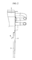
FIG. 2 is a partial enlarged cross-sectional view illustrating a side plate of the heat exchanger inFIG. 1 . -
FIG. 3 is a perspective view illustrating an interior of the indoor unit of the air conditioner according to the embodiment. -
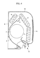
FIG. 4 is a vertical cross-section view illustrating the indoor unit of the air conditioner according to the embodiment. - Hereinafter, embodiments of the present invention will be described with reference to the accompanying drawings.
An indoor unit 1 of an air conditioner is provided with aheat exchanger 4 through which refrigerant passes, ablower 7, a motor, a drain pan, and the like in amain body casing 2. Themain body casing 2 includes abase 9 which is positioned at a rear side of the indoor unit 1, afront panel 10 provided at a front side of thebase 9, and the like. - As illustrated in
FIG. 1 , thefront panel 10 is provided with asuction port 11 and anair outlet 12. Air sucked from thesuction port 11 is introduced into theheat exchanger 4 by means of theblower 7. Then, after passing through theheat exchanger 4, cooled or heated air is blown indoor through theair outlet 12. - As illustrated in
FIG. 1 , theheat exchanger 4 is arranged along a longitudinal direction of themain body casing 2. Aside plate 5 is provided at one end of theheat exchanger 4 so as to be in contact with the main body of theheat exchanger 4 and aresin block 8 is provided at the other end of theheat exchanger 4. As illustrated inFIGS. 3 and4 , theheat exchanger 4 is arranged so as to surround theblower 7. - A
support portion 3 is formed on thebase 9 integrally with thebase 9. As illustrated inFIG. 1 , thesupport portion 3 has a plate-like portion. The plate-like portion is formed perpendicularly to the longitudinal direction of thebase 9 or to the right and left direction of the indoor unit 1. - Next, a configuration of the fixing means of the
heat exchanger 4 according to this embodiment will be described with reference toFIGS. 1 and2 .
Thesupport portion 3 is located inward in the longitudinal direction of theheat exchanger 4 relative to theside plate 5 of theheat exchanger 4. The "inward in the longitudinal direction of theheat exchanger 4" means an area located between both ends in the longitudinal direction of theheat exchanger 4. - Unlike a conventional side plate, the
side plate 5 of theheat exchanger 4 has anengagement portion 6. Theengagement portion 6 is, for example, of a plate-like member, and formed integrally with theside plate 5 and coupled to theside plate 5 so that it does not get loose upon an impact. Theengagement portion 6 is so configured to nip the plate-like portion of thesupport portion 3 of themain body casing 2. Theengagement portion 6 may be so springy that it is urged to theside plate 5 side. When theheat exchanger 4 is installed in themain body casing 2, theengagement portion 6 becomes in contact with the inner face side of thesupport portion 3 in the longitudinal direction of theheat exchanger 4. - Further, when the
heat exchanger 4 is installed in themain body casing 2, theside plate 5 becomes in contact with a face of thesupport portion 3 which is facing outward in the longitudinal direction of theheat exchanger 4 to nip thesupport portion 3 of themain body casing 2 together with theengagement portion 6. The "outward in the longitudinal direction of theheat exchanger 4" means an outer area outside the both ends of theheat exchanger 4 in the longitudinal direction. - Next, a function of the fixing means of the
heat exchanger 4 according to this embodiment will be described below.
According to the conventional art, the heat exchanger provided with a side plate having noengagement portion 6 of this embodiment is fixed to the main body casing by a bolt, which is inserted from the outside in the longitudinal direction of the heat exchanger into the support portion of the main body casing, or using an optional support component. - On the other hand, according to the present embodiment, the
side plate 5 and theengagement portion 6 coupled to theside plate 5 nip thesupport portion 3 so that theheat exchanger 4 is fixed to themain body casing 2 via thesupport portion 3. Thesupport portion 3 is formed integrally with themain body casing 2 and located inward in the longitudinal direction of theheat exchanger 4 relative to theside plate 5 of theheat exchanger 4. Theengagement portion 6 coupled to theside plate 5 of theheat exchanger 4 is in contact with the inner face side of thesupport portion 3. - When an impact is applied to the
main body casing 2 so that theheat exchanger 4 receives a force which moves itself outward in the longitudinal direction of theheat exchanger 4 relative to thesupport portion 3, theheat exchanger 4 attempts to move outward in the longitudinal direction. Unless theengagement portion 6 is provided, there is a possibility that theheat exchanger 4 may be moved without any support because theside plate 5 of theheat exchanger 4 is located at the outer side relative to thesupport portion 3. - According to this embodiment, the
engagement portion 6 is in contact with the inner face side of thesupport portion 3 in the longitudinal direction of theheat exchanger 4. Consequently, theheat exchanger 4 can be kept from being moved toward the outside in the longitudinal direction relative to thesupport portion 3 of theheat exchanger 4 and in connection with theside plate 5 of theheat exchanger 4. - As described above, according to this embodiment, the
heat exchanger 4 can be kept from being moved, thereby the quality of the air conditioner can also be improved. Additionally, theheat exchanger 4 can be fixed to themain body casing 2 without using any screw or any support component, and consequently, the number of necessary components can be reduced, thereby reducing manufacturing cost. - Although in the above-described embodiment, a case where the
engagement portion 6 is provided at a single position of theside plate 5 has been described, the present invention is not limited to this example. For example, theengagement portion 6 may be provided at two or more positions of theside plate 5. -
- 1
- Indoor unit
- 2
- Main body casing
- 3
- Support portion
- 4
- Heat exchanger
- 5
- Side plate (side panel)
- 6
- Engagement portion
- 7
- Blower
- 8
- Resin block
- 9
- Base
- 10
- Front panel
- 11
- Suction port
- 12
- Air outlet
Claims (2)
- An air conditioner comprising:a heat exchanger (4) arranged such that a longitudinal direction of the heat exchanger (4) is along a longitudinal direction of a main body casing (2); anda support portion (3) formed integrally with the main body casing (2), whereinthe heat exchanger has a side plate (5) provided at an end in the longitudinal direction of the heat exchanger (4);the support portion (3) is located inward in the longitudinal direction of the heat exchanger (4) relative to the side plate (5); andthe side plate (5) has an engagement portion (6) which is in contact with an inner face side of the support portion (3) in the longitudinal direction of the heat exchanger (4).
- The air conditioner according to claim 1, wherein the side plate (5) is in contact with a face of the support portion (3) which is facing outward in the longitudinal direction of the heat exchanger (4) so that the side plate (5) nips the support portion (5) together with the engagement portion (6).
Applications Claiming Priority (1)
| Application Number | Priority Date | Filing Date | Title |
|---|---|---|---|
| JP2012054369A JP6081068B2 (en) | 2012-03-12 | 2012-03-12 | Air conditioner |
Publications (2)
| Publication Number | Publication Date |
|---|---|
| EP2639520A2 true EP2639520A2 (en) | 2013-09-18 |
| EP2639520A3 EP2639520A3 (en) | 2018-04-18 |
Family
ID=47826987
Family Applications (1)
| Application Number | Title | Priority Date | Filing Date |
|---|---|---|---|
| EP13157729.8A Withdrawn EP2639520A3 (en) | 2012-03-12 | 2013-03-05 | Air conditioner |
Country Status (2)
| Country | Link |
|---|---|
| EP (1) | EP2639520A3 (en) |
| JP (1) | JP6081068B2 (en) |
Family Cites Families (6)
| Publication number | Priority date | Publication date | Assignee | Title |
|---|---|---|---|---|
| JP3354781B2 (en) * | 1996-01-30 | 2002-12-09 | 三菱重工業株式会社 | Air conditioner |
| US5896921A (en) * | 1997-05-27 | 1999-04-27 | Daewoo Electronics Co., Ltd. | Indoor unit of an air conditioner |
| JP2000179931A (en) * | 1998-12-17 | 2000-06-30 | Matsushita Electric Ind Co Ltd | Heat exchanger fixing device in air conditioner |
| JP2002318001A (en) * | 2001-04-20 | 2002-10-31 | Fujitsu General Ltd | Air conditioner |
| JP2003339461A (en) * | 2002-05-29 | 2003-12-02 | Sun Wave Ind Co Ltd | Lid fixture for inspection port |
| FR2933487B1 (en) * | 2008-07-04 | 2010-11-05 | Tecumseh Europe Sa | DEVICE FOR ASSEMBLING A FAN FOR A REFRIGERATION UNIT |
-
2012
- 2012-03-12 JP JP2012054369A patent/JP6081068B2/en active Active
-
2013
- 2013-03-05 EP EP13157729.8A patent/EP2639520A3/en not_active Withdrawn
Non-Patent Citations (1)
| Title |
|---|
| None * |
Also Published As
| Publication number | Publication date |
|---|---|
| JP2013190109A (en) | 2013-09-26 |
| JP6081068B2 (en) | 2017-02-15 |
| EP2639520A3 (en) | 2018-04-18 |
Similar Documents
| Publication | Publication Date | Title |
|---|---|---|
| US10619865B2 (en) | Air-conditioning unit | |
| CN203605369U (en) | Outdoor unit of air conditioner | |
| EP2952822B1 (en) | Outdoor unit for air-conditioning apparatus | |
| US9664461B2 (en) | Multi-poise condensate drain pan | |
| EP2921795A1 (en) | Outdoor unit of air conditioner | |
| CN104344473B (en) | The outdoor unit of air conditioner | |
| US10240853B2 (en) | Upflow condensate drain pan | |
| CN104422105B (en) | Air-conditioning | |
| US20110138844A1 (en) | Duct type air conditioner | |
| AU2013238794B2 (en) | Outdoor unit for air-conditioning apparatus and air-conditioning apparatus including the same | |
| US9671127B2 (en) | Multi-poise condensate drain pan | |
| JPWO2016075817A1 (en) | Air conditioner indoor unit | |
| US20170261224A1 (en) | Indoor unit | |
| EP2930441A1 (en) | Outdoor machine for air-conditioner | |
| CN107110522B (en) | The outdoor unit | |
| US20110138846A1 (en) | Duct type air conditioner | |
| JP6727411B2 (en) | Air conditioner indoor unit | |
| JP2017053577A (en) | Outdoor unit | |
| CN110291341B (en) | Wind direction changing mechanism | |
| CN106765597B (en) | Air conditioner wall-mounted unit and air conditioner | |
| US11371746B2 (en) | Indoor unit of air-conditioning apparatus | |
| US20150153096A1 (en) | Upflow condensate drain pan | |
| JP6081068B2 (en) | Air conditioner | |
| CN203928198U (en) | Air conditioner outdoor unit | |
| EP2568225A2 (en) | Air Conditioner |
Legal Events
| Date | Code | Title | Description |
|---|---|---|---|
| PUAI | Public reference made under article 153(3) epc to a published international application that has entered the european phase |
Free format text: ORIGINAL CODE: 0009012 |
|
| AK | Designated contracting states |
Kind code of ref document: A2 Designated state(s): AL AT BE BG CH CY CZ DE DK EE ES FI FR GB GR HR HU IE IS IT LI LT LU LV MC MK MT NL NO PL PT RO RS SE SI SK SM TR |
|
| AX | Request for extension of the european patent |
Extension state: BA ME |
|
| RAP1 | Party data changed (applicant data changed or rights of an application transferred) |
Owner name: MITSUBISHI HEAVY INDUSTRIES THERMAL SYSTEMS, LTD. |
|
| PUAL | Search report despatched |
Free format text: ORIGINAL CODE: 0009013 |
|
| AK | Designated contracting states |
Kind code of ref document: A3 Designated state(s): AL AT BE BG CH CY CZ DE DK EE ES FI FR GB GR HR HU IE IS IT LI LT LU LV MC MK MT NL NO PL PT RO RS SE SI SK SM TR |
|
| AX | Request for extension of the european patent |
Extension state: BA ME |
|
| RIC1 | Information provided on ipc code assigned before grant |
Ipc: F24F 13/30 20060101ALI20180309BHEP Ipc: F24F 13/20 20060101AFI20180309BHEP Ipc: F24F 1/00 20110101ALI20180309BHEP |
|
| STAA | Information on the status of an ep patent application or granted ep patent |
Free format text: STATUS: REQUEST FOR EXAMINATION WAS MADE |
|
| 17P | Request for examination filed |
Effective date: 20181016 |
|
| RBV | Designated contracting states (corrected) |
Designated state(s): AL AT BE BG CH CY CZ DE DK EE ES FI FR GB GR HR HU IE IS IT LI LT LU LV MC MK MT NL NO PL PT RO RS SE SI SK SM TR |
|
| GRAP | Despatch of communication of intention to grant a patent |
Free format text: ORIGINAL CODE: EPIDOSNIGR1 |
|
| STAA | Information on the status of an ep patent application or granted ep patent |
Free format text: STATUS: GRANT OF PATENT IS INTENDED |
|
| INTG | Intention to grant announced |
Effective date: 20190405 |
|
| STAA | Information on the status of an ep patent application or granted ep patent |
Free format text: STATUS: THE APPLICATION IS DEEMED TO BE WITHDRAWN |
|
| 18D | Application deemed to be withdrawn |
Effective date: 20190817 |