EP2639497A1 - Reflector assembly for use in a luminaire - Google Patents
Reflector assembly for use in a luminaire Download PDFInfo
- Publication number
- EP2639497A1 EP2639497A1 EP12290085.5A EP12290085A EP2639497A1 EP 2639497 A1 EP2639497 A1 EP 2639497A1 EP 12290085 A EP12290085 A EP 12290085A EP 2639497 A1 EP2639497 A1 EP 2639497A1
- Authority
- EP
- European Patent Office
- Prior art keywords
- reflector
- segments
- dome shaped
- periphery
- reflector segments
- Prior art date
- Legal status (The legal status is an assumption and is not a legal conclusion. Google has not performed a legal analysis and makes no representation as to the accuracy of the status listed.)
- Granted
Links
Images


Classifications
-
- F—MECHANICAL ENGINEERING; LIGHTING; HEATING; WEAPONS; BLASTING
- F21—LIGHTING
- F21V—FUNCTIONAL FEATURES OR DETAILS OF LIGHTING DEVICES OR SYSTEMS THEREOF; STRUCTURAL COMBINATIONS OF LIGHTING DEVICES WITH OTHER ARTICLES, NOT OTHERWISE PROVIDED FOR
- F21V7/00—Reflectors for light sources
- F21V7/0025—Combination of two or more reflectors for a single light source
-
- F—MECHANICAL ENGINEERING; LIGHTING; HEATING; WEAPONS; BLASTING
- F21—LIGHTING
- F21V—FUNCTIONAL FEATURES OR DETAILS OF LIGHTING DEVICES OR SYSTEMS THEREOF; STRUCTURAL COMBINATIONS OF LIGHTING DEVICES WITH OTHER ARTICLES, NOT OTHERWISE PROVIDED FOR
- F21V17/00—Fastening of component parts of lighting devices, e.g. shades, globes, refractors, reflectors, filters, screens, grids or protective cages
- F21V17/002—Fastening of component parts of lighting devices, e.g. shades, globes, refractors, reflectors, filters, screens, grids or protective cages with provision for interchangeability, i.e. component parts being especially adapted to be replaced by another part with the same or a different function
-
- F—MECHANICAL ENGINEERING; LIGHTING; HEATING; WEAPONS; BLASTING
- F21—LIGHTING
- F21V—FUNCTIONAL FEATURES OR DETAILS OF LIGHTING DEVICES OR SYSTEMS THEREOF; STRUCTURAL COMBINATIONS OF LIGHTING DEVICES WITH OTHER ARTICLES, NOT OTHERWISE PROVIDED FOR
- F21V17/00—Fastening of component parts of lighting devices, e.g. shades, globes, refractors, reflectors, filters, screens, grids or protective cages
- F21V17/007—Fastening of component parts of lighting devices, e.g. shades, globes, refractors, reflectors, filters, screens, grids or protective cages with provision for shipment or storage
-
- F—MECHANICAL ENGINEERING; LIGHTING; HEATING; WEAPONS; BLASTING
- F21—LIGHTING
- F21V—FUNCTIONAL FEATURES OR DETAILS OF LIGHTING DEVICES OR SYSTEMS THEREOF; STRUCTURAL COMBINATIONS OF LIGHTING DEVICES WITH OTHER ARTICLES, NOT OTHERWISE PROVIDED FOR
- F21V7/00—Reflectors for light sources
- F21V7/10—Construction
-
- F—MECHANICAL ENGINEERING; LIGHTING; HEATING; WEAPONS; BLASTING
- F21—LIGHTING
- F21V—FUNCTIONAL FEATURES OR DETAILS OF LIGHTING DEVICES OR SYSTEMS THEREOF; STRUCTURAL COMBINATIONS OF LIGHTING DEVICES WITH OTHER ARTICLES, NOT OTHERWISE PROVIDED FOR
- F21V7/00—Reflectors for light sources
- F21V7/22—Reflectors for light sources characterised by materials, surface treatments or coatings, e.g. dichroic reflectors
- F21V7/24—Reflectors for light sources characterised by materials, surface treatments or coatings, e.g. dichroic reflectors characterised by the material
-
- F—MECHANICAL ENGINEERING; LIGHTING; HEATING; WEAPONS; BLASTING
- F21—LIGHTING
- F21V—FUNCTIONAL FEATURES OR DETAILS OF LIGHTING DEVICES OR SYSTEMS THEREOF; STRUCTURAL COMBINATIONS OF LIGHTING DEVICES WITH OTHER ARTICLES, NOT OTHERWISE PROVIDED FOR
- F21V7/00—Reflectors for light sources
-
- F—MECHANICAL ENGINEERING; LIGHTING; HEATING; WEAPONS; BLASTING
- F21—LIGHTING
- F21W—INDEXING SCHEME ASSOCIATED WITH SUBCLASSES F21K, F21L, F21S and F21V, RELATING TO USES OR APPLICATIONS OF LIGHTING DEVICES OR SYSTEMS
- F21W2131/00—Use or application of lighting devices or systems not provided for in codes F21W2102/00-F21W2121/00
- F21W2131/10—Outdoor lighting
- F21W2131/105—Outdoor lighting of arenas or the like
-
- F—MECHANICAL ENGINEERING; LIGHTING; HEATING; WEAPONS; BLASTING
- F21—LIGHTING
- F21W—INDEXING SCHEME ASSOCIATED WITH SUBCLASSES F21K, F21L, F21S and F21V, RELATING TO USES OR APPLICATIONS OF LIGHTING DEVICES OR SYSTEMS
- F21W2131/00—Use or application of lighting devices or systems not provided for in codes F21W2102/00-F21W2121/00
- F21W2131/10—Outdoor lighting
- F21W2131/107—Outdoor lighting of the exterior of buildings
Definitions
- the present invention relates to a reflector assembly for use in a luminaire provided to brightly illuminate a target area wherein said luminaire can be used for floodlight, sport and area lighting applications. Further, the present invention is directed to a method for adapting the light emitting characteristics of a reflector assembly.
- Lighting devices with incandescent or arc discharge lamps are routinely used to illuminate the exterior areas of commercial businesses for purposes of enhancing the appearance of the business at night and for promoting interest in the goods and services of the business by actual and potential customers.
- Restaurants and shopping malls represent just a few of the business types for which exterior luminaires play an important role in marketing and facilitating product sales.
- other facilities such as parking areas, outdoor sports stadiums or indoor arenas usually require intensive illumination of specific areas, e.g. in order to provide lighting that allows a sport to take place safely and provide good viewing conditions, both in visibility of the sports action and comfort of the audience.
- reflectors are commonly used to reflect light emitted from at least one light source.
- the reflectors have a dome shaped configuration and focus the reflected light in desired patterns and with desired levels of intensity so that energy costs are minimized while maximum lighting is achieved.
- Reflectors also serve to protect the light source, with some reflectors providing a protective enclosure to protect the light source from weather, dust, moisture, and the like.
- a reflector is usually the only - or at least the most relevant - optical element of a luminaire which is available for shaping the light emitted into a desired pattern. Since depending on the application a luminaire is used for often a very specific light distribution with respect to the beam aperture and the peak intensity is desired, floodlighting systems are commonly offered with a large variety of reflectors which then are specifically selected to meet the requirements of the application.
- the inventive solution is based on the concept of using a reflector which includes multiple segments assembled to each other in order to finally form the reflective surface.
- the emission of the luminaire can be easily and efficiently adapted to meet the lighting requirements of multiple applications.
- the "construction kit" solution proposed in accordance with the present invention allows manufacturing reflectors having different emission characteristics by simply selecting a specific combination of reflector segments with appropriate reflection characteristics. Even more, the resulting reflectors - though they emit light in different ways - always have identical shapes and thus can be used with identical luminaire housings and/or supporting structures and preferably also with identical light sources. Accordingly, luminaires for floodlighting applications can be obtained with a wide variety of light emission characteristics and thus suitable for different applications at reasonable costs.
- a reflector assembly for use in a luminaire in particular for floodlight, sport and area lighting applications wherein said reflector assembly forms a dome shaped structure for accommodating at least one light source therein and emitting the light of said light source via an opening of said dome shaped structure wherein said reflector comprises a plurality of reflector segments which are arranged to form together the dome shaped structure and wherein at least two of said reflector segments have different reflection characteristics.
- the reflector segments are adapted to form a continuously shaped reflective surface at the inner surface of the dome shaped structure.
- the reflector segments can have a shape and means to connect to a neighboring segment in such a way that a continuous and smooth transition between both segments is obtained. In this way, the resulting reflector assembly is almost identical to a one-piece reflector regarding the quality of the reflective surface but obviously can be manufactured in a much easier and more cost efficient way.
- the reflector segments comprise one central reflector segment and at least two periphery reflector segments which extend from the central reflector segment to the light emitting opening of the dome shaped structure.
- the central reflector segment thus forms the basic element of the inventive reflector assembly and provides a reflective surface which is located behind the light source.
- the periphery reflector segments form reflective surfaces at the sides and in front of the light source and are mainly responsible for shaping the emitted light into the desired form.
- the periphery reflector segments substantially have an identical shape. This solution not only allows reducing the number of different parts to a minimum but also facilitates the assembly of the final reflector structure.
- said reflector segments comprise one central reflector segment and four periphery reflector segments wherein in particular two opposed periphery reflector segments have identical reflection characteristics.
- This characteristic can be obtained by providing two opposed periphery reflector segments which form lateral reflective surfaces and are identical with respect to their reflection characteristics.
- the other periphery reflector segments form a top reflective surface and a bottom reflective surface and are individually selected to finally shape the emitted light beam.
- the reflection characteristics of these two further segments can differ from each other but also from the reflection characteristics of the two lateral segments.
- said reflector segments are adapted to form at least one opening in the reflective surface for inserting or holding a light source.
- the longitudinal light source is preferably located within the reflector such that it extends through a bottom portion of the dome structure. Two openings arranged in this bottom portion of the reflector allow the light source to extend with their ends to lamp holders which are provided in the surrounding area of the reflector.
- a holding structure for holding the light source can extend through the opening(s) in the interior of the reflector dome to safely hold the light source there.
- the inventive concept is based on the idea of using a reflector which includes multiple segments assembled to each other in order to finally form the reflective surface.
- the reflector 1 consists of an assembly of five different parts or segments 2-5 made preferably in high reflective aluminum.
- the reflector 1 comprises a center portion formed by one central reflector segment 2 and a surrounding reflective surface extending from the center portion to the opening of the reflector 1 which is formed by four periphery reflector segments 3-5.
- these reflector segments 2-5 provide a continuous concave shape similar to a conventional one-piece reflector.
- a sixth reflector segment 6 can be added which extends through the interior of the dome structure and forms a deflector. This optional deflector segment 6 is for example used in case a strong asymmetric light distribution is desired.
- the four periphery reflector segments 3-5 have an almost identical shape wherein one reflector segment is shown in isolated form in Figures 4 to 7 . It forms a quarter of the rotational dome structure and thus shows a rotational symmetry with respect to an axis I extending through the center of the reflector assembly perpendicular to the reflector opening (see Figure 2 ). In this way, the four periphery reflector segments 3-5 form in the finally assembled form a smooth and continuous reflective surface for distributing the light emitted by the light source 100 in a desired manner.
- the periphery reflector segments 3-5 have an almost identical shape, it should be clarified that this explanation refers to the general form of the reflective surface of the segments.
- the reflector segments 3-5 can slightly differ from each other in the portion adjacent to the central reflector segment 2.
- two of the periphery reflector segments are at their sides adjacent to the central segment 2 provided with a recess 7 (see Figures 4 to 6 ) having approximately the form of a semi-circle.
- these semi-circular recesses 7 are cut into the reflector segments after their production requiring only one single die-cast form for manufacturing the periphery reflector segments.
- the four periphery reflector segments have an - almost - identical shape, they are usually made from different materials and thus have different optical characteristics. By combining reflector segments of different materials, the light distribution and intensity finally obtained can be adapted in order to meet the requirements of a floodlighting application.
- connection element 10 which extends over the entire connection region at the outer surface of the two segments 3-5.
- the connection elements 10 ensure that the reflector segments 3-5 are secured in the adjacent position and that no gaps occur between two segments 3-5. In this way, the desired smooth and continuous reflective surface is obtained.
- an end plate 12 is provided having in the shown example a quadratic outer shape and a circular opening corresponding to the opening of the dome formed by the peripheral reflector segments 3-5.
- This end plate 12 stabilizes the dome structure and is connected to the reflector segments 3-5 as well as to end portions of the connecting elements 10.
- the peripheral reflector segments 3-5 preferably have flanged end portions 9 allowing to fix the reflector segments 3-5 to the end plate 12 by bolts or screws 13.
- the central reflector segment 2 is covered by a bottom cap 15 stabilizing this bottom area of the reflector 1 by slightly extending with a flanged end portion 16 over the end regions of the peripheral reflector segments 3-5.
- the flanged end portion 16 is also adapted for a connection with the four connecting elements 10 by using further bolts or screws 13 and comprises two lateral openings 17 aligned with the openings 8 in the reflector dome.
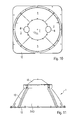
- the finally obtained reflector 1 is shown in the assembled form in Figures 10 and 11 and exhibits stability sufficient for its further use in floodlighting luminaires as well as an excellent optical reflective surface. It can be finally inserted in a casing or holding structure to form a floodlighting luminaire 110 as shown in Figure 12 .
- the dome structure of the reflector could be formed by alternatively shaped reflector segments and it is in particular not necessary that four peripheral reflector segments are used which have an identical shape. It would for example also be possible to use only two peripheral reflector segments or to use even more segments which have different shapes but can again be assembled to the desired reflector shape.
- the resulting reflector structure could differ from the one shown in the figures and could for example be more similar to truncated pyramid or the like.
- the possibilities to adapt the optical characteristics of the resulting reflector are increased in case a higher number of reflector segments is used to form the reflector dome.
- assembling the segments to the final structure is then more complicate and care should be taken that no gaps occur which could significantly impair the optical characteristics of the reflector.
- the shown embodiment provides a perfect compromise since the effort to manufacture the reflector is still low while the optical characteristics of the reflector can nevertheless be adapted in a relatively wide range.
Landscapes
- Engineering & Computer Science (AREA)
- General Engineering & Computer Science (AREA)
- Non-Portable Lighting Devices Or Systems Thereof (AREA)
- Securing Globes, Refractors, Reflectors Or The Like (AREA)
Abstract
Description
- The present invention relates to a reflector assembly for use in a luminaire provided to brightly illuminate a target area wherein said luminaire can be used for floodlight, sport and area lighting applications. Further, the present invention is directed to a method for adapting the light emitting characteristics of a reflector assembly.
- Lighting devices with incandescent or arc discharge lamps are routinely used to illuminate the exterior areas of commercial businesses for purposes of enhancing the appearance of the business at night and for promoting interest in the goods and services of the business by actual and potential customers. Restaurants and shopping malls represent just a few of the business types for which exterior luminaires play an important role in marketing and facilitating product sales. However, also other facilities such as parking areas, outdoor sports stadiums or indoor arenas usually require intensive illumination of specific areas, e.g. in order to provide lighting that allows a sport to take place safely and provide good viewing conditions, both in visibility of the sports action and comfort of the audience.
- For lighting applications as mentioned above, reflectors are commonly used to reflect light emitted from at least one light source. The reflectors have a dome shaped configuration and focus the reflected light in desired patterns and with desired levels of intensity so that energy costs are minimized while maximum lighting is achieved. Reflectors also serve to protect the light source, with some reflectors providing a protective enclosure to protect the light source from weather, dust, moisture, and the like.
- In particular in floodlighting systems used for applications as mentioned above, a reflector is usually the only - or at least the most relevant - optical element of a luminaire which is available for shaping the light emitted into a desired pattern. Since depending on the application a luminaire is used for often a very specific light distribution with respect to the beam aperture and the peak intensity is desired, floodlighting systems are commonly offered with a large variety of reflectors which then are specifically selected to meet the requirements of the application.
- Obviously, producing and storing a high number of different types of reflectors is not desirable. Due to their hollow, bulky shape, reflectors typically require specialized equipment for their manufacture, and take up considerable amounts of room after manufacture, making them expensive to manufacture, store and/or ship. Particularly in industrial-type reflectors or reflectors for floodlighting systems where the light sources and associated reflectors are often relatively large, shipping and storage becomes a major cost but also the equipment for manufacturing such reflectors like injections moulds or the like is expensive.
- There is thus a need to provide a solution for facilitating the manufacture of a reflector which can be used in particular in a floodlighting system and provides a desired specific light emission characteristic.
- In accordance with the present invention, the above object is solved by a reflector assembly as defined in independent claim 1 and by a method as defined in
claim 9. Preferred embodiments and further developments of the present invention are subject matter of the dependent claims. - The inventive solution is based on the concept of using a reflector which includes multiple segments assembled to each other in order to finally form the reflective surface. By providing segments having different reflection characteristics, the emission of the luminaire can be easily and efficiently adapted to meet the lighting requirements of multiple applications. In particular, the "construction kit" solution proposed in accordance with the present invention allows manufacturing reflectors having different emission characteristics by simply selecting a specific combination of reflector segments with appropriate reflection characteristics. Even more, the resulting reflectors - though they emit light in different ways - always have identical shapes and thus can be used with identical luminaire housings and/or supporting structures and preferably also with identical light sources. Accordingly, luminaires for floodlighting applications can be obtained with a wide variety of light emission characteristics and thus suitable for different applications at reasonable costs.
- Thus, in accordance with the present invention a reflector assembly for use in a luminaire in particular for floodlight, sport and area lighting applications is provided wherein said reflector assembly forms a dome shaped structure for accommodating at least one light source therein and emitting the light of said light source via an opening of said dome shaped structure wherein said reflector comprises a plurality of reflector segments which are arranged to form together the dome shaped structure and wherein at least two of said reflector segments have different reflection characteristics.
- Preferably, the reflector segments are adapted to form a continuously shaped reflective surface at the inner surface of the dome shaped structure. In particular, the reflector segments can have a shape and means to connect to a neighboring segment in such a way that a continuous and smooth transition between both segments is obtained. In this way, the resulting reflector assembly is almost identical to a one-piece reflector regarding the quality of the reflective surface but obviously can be manufactured in a much easier and more cost efficient way.
- Further preferably, the reflector segments comprise one central reflector segment and at least two periphery reflector segments which extend from the central reflector segment to the light emitting opening of the dome shaped structure. The central reflector segment thus forms the basic element of the inventive reflector assembly and provides a reflective surface which is located behind the light source. In contrast to this, the periphery reflector segments form reflective surfaces at the sides and in front of the light source and are mainly responsible for shaping the emitted light into the desired form. By selecting periphery reflector segments with specific reflection characteristics, the light distribution can be adapted in an extremely efficient way.
- According to a preferred embodiment of the present invention, the periphery reflector segments substantially have an identical shape. This solution not only allows reducing the number of different parts to a minimum but also facilitates the assembly of the final reflector structure.
- In a further preferred embodiment of the present invention, said reflector segments comprise one central reflector segment and four periphery reflector segments wherein in particular two opposed periphery reflector segments have identical reflection characteristics. In almost all applications of the inventive reflector assembly, it is desired that the light is emitted symmetrically to both sides of a luminaire. This characteristic can be obtained by providing two opposed periphery reflector segments which form lateral reflective surfaces and are identical with respect to their reflection characteristics. In contrast to this, the other periphery reflector segments form a top reflective surface and a bottom reflective surface and are individually selected to finally shape the emitted light beam. The reflection characteristics of these two further segments can differ from each other but also from the reflection characteristics of the two lateral segments.
- Further preferably, said reflector segments are adapted to form at least one opening in the reflective surface for inserting or holding a light source. Similar to a classical one-piece reflector, the longitudinal light source is preferably located within the reflector such that it extends through a bottom portion of the dome structure. Two openings arranged in this bottom portion of the reflector allow the light source to extend with their ends to lamp holders which are provided in the surrounding area of the reflector. Alternatively, a holding structure for holding the light source can extend through the opening(s) in the interior of the reflector dome to safely hold the light source there.
- In the following, the present invention and advantages thereof are explained in more detail with reference to the accompanying drawings.
- Figures 1 to 3
- show the inventive concept of a multi-part reflector assembly;
- Figures 4 to 7
- show different views of a periphery reflector segment used in the inventive reflector assembly;
- Figures 8 and 9
- show exploded views of the final reflector assembly;
- Figures 10 and 11
- show the inventive reflector in an assembled form;
- Figure 12
- shows as floodlighting luminaire comprising the inventive reflector assembly.
- The inventive concept is at first explained with reference to
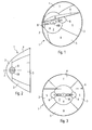
Figures 1 to 3 which show different views of a rotational, dome shaped reflector assembly comprising five separate reflector segments - and one further optional reflector segment - which are assembled to the dome structure. In these Figures, only the light source and the reflector segments are shown but no further elements serving to connect the segments to each other. These further elements for finally forming the reflector are shown in the following figures and explained further below. - As mentioned above, the inventive concept is based on the idea of using a reflector which includes multiple segments assembled to each other in order to finally form the reflective surface. By using reflector segments with different optical characteristics, a wide range of lighting distributions for different floodlighting applications can be obtained.
- In the embodiment shown in
Figures 1 to 3 , the reflector 1 consists of an assembly of five different parts or segments 2-5 made preferably in high reflective aluminum. In particular, the reflector 1 comprises a center portion formed by onecentral reflector segment 2 and a surrounding reflective surface extending from the center portion to the opening of the reflector 1 which is formed by four periphery reflector segments 3-5. In the assembled form, these reflector segments 2-5 provide a continuous concave shape similar to a conventional one-piece reflector. If required, asixth reflector segment 6 can be added which extends through the interior of the dome structure and forms a deflector. Thisoptional deflector segment 6 is for example used in case a strong asymmetric light distribution is desired. - In the preferred embodiment shown in the Figures, the four periphery reflector segments 3-5 have an almost identical shape wherein one reflector segment is shown in isolated form in
Figures 4 to 7 . It forms a quarter of the rotational dome structure and thus shows a rotational symmetry with respect to an axis I extending through the center of the reflector assembly perpendicular to the reflector opening (seeFigure 2 ). In this way, the four periphery reflector segments 3-5 form in the finally assembled form a smooth and continuous reflective surface for distributing the light emitted by thelight source 100 in a desired manner. - When it was explained above that the periphery reflector segments 3-5 have an almost identical shape, it should be clarified that this explanation refers to the general form of the reflective surface of the segments. As shown
Figures 1 to 3 , the reflector segments 3-5 can slightly differ from each other in the portion adjacent to thecentral reflector segment 2. In particular, preferably two of the periphery reflector segments are at their sides adjacent to thecentral segment 2 provided with a recess 7 (seeFigures 4 to 6 ) having approximately the form of a semi-circle. Together with corresponding recesses provided at thecentral reflector segment 2, they form twocircular openings 8 which are arranged opposite to each other in the bottom region of the reflector dome and can be used to insert thelight source 100 or allow that supporting elements extend from an exterior of the reflector 1 through theopenings 8 in the interior of the reflector 1 for holding thelight source 100 there. Preferably, thesesemi-circular recesses 7 are cut into the reflector segments after their production requiring only one single die-cast form for manufacturing the periphery reflector segments. - Although the four periphery reflector segments have an - almost - identical shape, they are usually made from different materials and thus have different optical characteristics. By combining reflector segments of different materials, the light distribution and intensity finally obtained can be adapted in order to meet the requirements of a floodlighting application.
- The effect of changing the reflector material for the different segments can be seen from the following Table which shows the peak intensity (in cd/klm) at a target area and the resulting beam shape for different material combinations. In all examples, an identical light source was used:
material → resulting beam ↓ Anodized 87% Miro4 Extra Bright Miro7 Matt Miro9 Hammered Miro20 Bright Diffuse Intensive 25000 cd/klm R S/T/B/D Semi-Intensive 18000 cd/klm R D S/T/B Semi-Extensive 11600 cd/klm R D T/B S Extensive 8000 cd/klm R D S/T/B Elliptical 5500 cd/klm R D S/T/B - The letters in the table above refer to the different reflector segments as follows:
- R:
- central reflector segment (2)
- S:
- side reflector segment (3)
- T:
- top reflector segment (4)
- B:
- bottom reflector segment (5)
- D:
- deflector reflector segment (6)
- The results summarized in this table clearly show that the selection of the material for the different reflector segments has a significant influence on the resulting light distribution. It is thus indeed possible to adapt the characteristics of a reflector by specifically combining different materials although the shape of the reflector segments is always identical. Even more, not only the shape of the reflector segments does not change but also the resulting shape of the finally assembled reflector is always the same. Accordingly, all further elements of the luminaire, in particular the means for connecting the reflector segments to each other and also a holding structure for holding the reflector within a luminaire are generally the same and can be used in all cases independent from the actual reflector characteristics. Floodlighting luminaires having very different characteristics can thus be obtained in a cost efficient way on the basis of the present invention.
- Whereas the figures so far only showed the general concept of combining the reflector elements to the final reflector dome,
Figures 8 to 11 show in more detail how the segments are connected to each other. - In particular, the exploded views of
Figures 8 and 9 show that two adjacent periphery reflector segments 3-5 are interconnected by aconnection element 10 which extends over the entire connection region at the outer surface of the two segments 3-5. Theconnection elements 10 ensure that the reflector segments 3-5 are secured in the adjacent position and that no gaps occur between two segments 3-5. In this way, the desired smooth and continuous reflective surface is obtained. - At the reflector opening, an
end plate 12 is provided having in the shown example a quadratic outer shape and a circular opening corresponding to the opening of the dome formed by the peripheral reflector segments 3-5. Thisend plate 12 stabilizes the dome structure and is connected to the reflector segments 3-5 as well as to end portions of the connectingelements 10. In this regard, the peripheral reflector segments 3-5 preferably haveflanged end portions 9 allowing to fix the reflector segments 3-5 to theend plate 12 by bolts or screws 13. - At the bottom portion of the reflector 1, the
central reflector segment 2 is covered by abottom cap 15 stabilizing this bottom area of the reflector 1 by slightly extending with aflanged end portion 16 over the end regions of the peripheral reflector segments 3-5. Theflanged end portion 16 is also adapted for a connection with the four connectingelements 10 by using further bolts or screws 13 and comprises twolateral openings 17 aligned with theopenings 8 in the reflector dome. The finally obtained reflector 1 is shown in the assembled form inFigures 10 and 11 and exhibits stability sufficient for its further use in floodlighting luminaires as well as an excellent optical reflective surface. It can be finally inserted in a casing or holding structure to form afloodlighting luminaire 110 as shown inFigure 12 . - Several alternatives to the preferred embodiment shown in the figures are possible. In particular, the means for interconnecting the segments and stabilizing the reflector structure can of course be designed in an alternative way.
- Further, the dome structure of the reflector could be formed by alternatively shaped reflector segments and it is in particular not necessary that four peripheral reflector segments are used which have an identical shape. It would for example also be possible to use only two peripheral reflector segments or to use even more segments which have different shapes but can again be assembled to the desired reflector shape.
- Further, the resulting reflector structure could differ from the one shown in the figures and could for example be more similar to truncated pyramid or the like.
- Obviously, the possibilities to adapt the optical characteristics of the resulting reflector are increased in case a higher number of reflector segments is used to form the reflector dome. On the other hand, assembling the segments to the final structure is then more complicate and care should be taken that no gaps occur which could significantly impair the optical characteristics of the reflector. In this regard, the shown embodiment provides a perfect compromise since the effort to manufacture the reflector is still low while the optical characteristics of the reflector can nevertheless be adapted in a relatively wide range.
Claims (15)
- Reflector assembly (1) for use in a luminaire (110) in particular for floodlight, sport and area lighting applications,
said reflector assembly (1) forming a dome shaped structure for accommodating at least one light source (100) therein and emitting the light of said light source (100) via an opening of said dome shaped structure,
characterized in that said reflector comprises a plurality of reflector segments (2-5) which are arranged to form together the dome shaped structure wherein at least two of said reflector segments (2-5) have different reflection characteristics. - Reflector assembly according to claim 1,
wherein the reflector segments (2-5) form a continuously shaped reflective surface. - Reflector assembly according to claim 1 or 2,
wherein said reflector segments (2-6) comprise one central reflector segment (2) and at least two periphery reflector segments (3-5) extending from the central reflector segment (2) to the opening of the dome shaped structure. - Reflector assembly according to claim 3,
wherein said periphery reflector segments (3-5) substantially have an identical shape. - Reflector assembly according to claim 4,
wherein said reflector segments (2-5) comprise one central reflector segment (2) and four periphery reflector segments (3-5). - Reflector assembly according to claim 5,
wherein two opposed periphery reflector segments (3) have identical reflection characteristics. - Reflector assembly according to any one of the preceding claims,
wherein said reflector segments (2-5) are adapted to form at least one opening in the reflective surface for inserting or holding a light source (100). - Reflector assembly according to any one of the preceding claims,
comprising further means for connecting the reflector segments (2-5) to each other. - Method for manufacturing a dome shaped reflector (1) comprising assembling a plurality of reflector segments (2-5) to form together the dome shaped structure, wherein at least two of said reflector segments (2-5) have different reflection characteristics.
- Method for manufacturing a dome shaped reflector according to claim 9,
wherein the reflector segments (2-5) form a continuously shaped reflective surface. - Method for manufacturing a dome shaped reflector according to claim 9 or 10, wherein said reflector segments (2-6) comprise one central reflector segment (2) and at least two periphery reflector segments (3-5) extending from the central reflector segment (2) to the opening of the dome shaped structure.
- Method for manufacturing a dome shaped reflector according to claim 11, wherein said periphery reflector segments (3-5) substantially have an identical shape.
- Method for manufacturing a dome shaped reflector according to claim 12, wherein said reflector segments (2-5) comprise one central reflector segment (2) and four periphery reflector segments (3-5).
- Method for manufacturing a dome shaped reflector according to claim 13, wherein two opposed periphery reflector segments (3) have identical reflection characteristics.
- Method for manufacturing a dome shaped reflector according to one of claims 9 to 14,
wherein said reflector segments (2-5) are adapted to form at least one opening in the reflective surface for inserting or holding a light source (100).
Priority Applications (4)
| Application Number | Priority Date | Filing Date | Title |
|---|---|---|---|
| EP12290085.5A EP2639497B1 (en) | 2012-03-12 | 2012-03-12 | Reflector assembly for use in a luminaire |
| CN201380022568.7A CN104302972B (en) | 2012-03-12 | 2013-03-11 | Reflector assembly for use in a luminaire |
| RU2014138618A RU2630895C2 (en) | 2012-03-12 | 2013-03-11 | Assembled reflector for use in lighting device |
| PCT/EP2013/054873 WO2013135626A1 (en) | 2012-03-12 | 2013-03-11 | Reflector assembly for use in a luminaire |
Applications Claiming Priority (1)
| Application Number | Priority Date | Filing Date | Title |
|---|---|---|---|
| EP12290085.5A EP2639497B1 (en) | 2012-03-12 | 2012-03-12 | Reflector assembly for use in a luminaire |
Publications (2)
| Publication Number | Publication Date |
|---|---|
| EP2639497A1 true EP2639497A1 (en) | 2013-09-18 |
| EP2639497B1 EP2639497B1 (en) | 2019-11-13 |
Family
ID=47884317
Family Applications (1)
| Application Number | Title | Priority Date | Filing Date |
|---|---|---|---|
| EP12290085.5A Active EP2639497B1 (en) | 2012-03-12 | 2012-03-12 | Reflector assembly for use in a luminaire |
Country Status (4)
| Country | Link |
|---|---|
| EP (1) | EP2639497B1 (en) |
| CN (1) | CN104302972B (en) |
| RU (1) | RU2630895C2 (en) |
| WO (1) | WO2013135626A1 (en) |
Families Citing this family (1)
| Publication number | Priority date | Publication date | Assignee | Title |
|---|---|---|---|---|
| GB2612190B (en) * | 2021-10-05 | 2025-01-08 | Karle Stefan | Lighting device |
Citations (8)
| Publication number | Priority date | Publication date | Assignee | Title |
|---|---|---|---|---|
| US707982A (en) * | 1902-06-02 | 1902-08-26 | Frank J Mayhew | Head or search light. |
| US5287259A (en) * | 1991-11-27 | 1994-02-15 | Lorin Industries, Inc. | Light reflector assembly |
| US5971569A (en) * | 1997-06-11 | 1999-10-26 | Steris Corporation | Surgical light with stacked elliptical reflector |
| US6152583A (en) * | 1998-02-20 | 2000-11-28 | Genlyte Thomas Group Llc | Adjustable luminaire having pivotable lamp and reflector assembly |
| US6203176B1 (en) * | 1998-12-14 | 2001-03-20 | Musco Corporation | Increased efficiency light fixture, reflector, and method |
| US6382803B1 (en) * | 2000-05-02 | 2002-05-07 | Nsi Enterprises, Inc. | Faceted reflector assembly |
| JP2007250231A (en) * | 2006-03-14 | 2007-09-27 | Mitsubishi Electric Corp | lighting equipment |
| US20090268456A1 (en) * | 2008-04-28 | 2009-10-29 | Auer Lighting Gmbh | High performance luminaire with a lamp and a reflector |
Family Cites Families (5)
| Publication number | Priority date | Publication date | Assignee | Title |
|---|---|---|---|---|
| US5402327A (en) * | 1992-01-14 | 1995-03-28 | Musco Corporation | Means and method for highly controllable lighting |
| CN100545506C (en) * | 2004-10-29 | 2009-09-30 | 文星日 | lighting fixtures |
| CN2747463Y (en) * | 2004-10-29 | 2005-12-21 | 文星日 | Reflection board for illumination |
| CN101142441B (en) * | 2005-01-18 | 2012-07-04 | 马斯科公司 | Modified reflector surface to redirect off-field side light onto field |
| RU99104U1 (en) * | 2010-06-18 | 2010-11-10 | Общество с ограниченной ответственностью "РоСАТ ЦЕНТР" | MODULAR LED SPOTLIGHT |
-
2012
- 2012-03-12 EP EP12290085.5A patent/EP2639497B1/en active Active
-
2013
- 2013-03-11 WO PCT/EP2013/054873 patent/WO2013135626A1/en not_active Ceased
- 2013-03-11 CN CN201380022568.7A patent/CN104302972B/en not_active Expired - Fee Related
- 2013-03-11 RU RU2014138618A patent/RU2630895C2/en not_active IP Right Cessation
Patent Citations (8)
| Publication number | Priority date | Publication date | Assignee | Title |
|---|---|---|---|---|
| US707982A (en) * | 1902-06-02 | 1902-08-26 | Frank J Mayhew | Head or search light. |
| US5287259A (en) * | 1991-11-27 | 1994-02-15 | Lorin Industries, Inc. | Light reflector assembly |
| US5971569A (en) * | 1997-06-11 | 1999-10-26 | Steris Corporation | Surgical light with stacked elliptical reflector |
| US6152583A (en) * | 1998-02-20 | 2000-11-28 | Genlyte Thomas Group Llc | Adjustable luminaire having pivotable lamp and reflector assembly |
| US6203176B1 (en) * | 1998-12-14 | 2001-03-20 | Musco Corporation | Increased efficiency light fixture, reflector, and method |
| US6382803B1 (en) * | 2000-05-02 | 2002-05-07 | Nsi Enterprises, Inc. | Faceted reflector assembly |
| JP2007250231A (en) * | 2006-03-14 | 2007-09-27 | Mitsubishi Electric Corp | lighting equipment |
| US20090268456A1 (en) * | 2008-04-28 | 2009-10-29 | Auer Lighting Gmbh | High performance luminaire with a lamp and a reflector |
Also Published As
| Publication number | Publication date |
|---|---|
| EP2639497B1 (en) | 2019-11-13 |
| RU2630895C2 (en) | 2017-09-14 |
| CN104302972A (en) | 2015-01-21 |
| CN104302972B (en) | 2017-05-24 |
| RU2014138618A (en) | 2016-05-10 |
| WO2013135626A1 (en) | 2013-09-19 |
Similar Documents
| Publication | Publication Date | Title |
|---|---|---|
| US7008079B2 (en) | Composite reflecting surface for linear LED array | |
| US7520636B2 (en) | Luminaire comprising LEDs | |
| US20130141908A1 (en) | Miniature cellular structure for retrofit led lamp secondary optics | |
| US7731395B2 (en) | Linear lenses for LEDs | |
| US7591567B2 (en) | Luminaire with a compound parabolic reflector | |
| US8162511B1 (en) | Full or near-full cut-off visor for light fixture | |
| US8814384B2 (en) | Light having LED modules | |
| US8579470B1 (en) | LED illumination source with improved visual characteristics | |
| US10670207B2 (en) | Lamp | |
| US20110310619A1 (en) | Lens for led lamps | |
| EP2708804A1 (en) | Lens, LED module and illumination system having same | |
| US11555582B2 (en) | Systems and methods for assembling a light engine | |
| US20060176701A1 (en) | Reflector-baffle for luminaires | |
| EP2639497B1 (en) | Reflector assembly for use in a luminaire | |
| WO2015125557A1 (en) | Illumination device | |
| US20110044054A1 (en) | Modified reflector surface to redirect off-field side light onto field | |
| US8360605B2 (en) | LED luminaire | |
| JP2009245621A (en) | Outdoor illuminating light unit and outdoor illuminating light | |
| CN101142437B (en) | Highly reflective lighting fixture visor | |
| US20190338913A1 (en) | Venue light including variable led array size etched lens and segmented reflector | |
| US20060274532A1 (en) | High-reflectance strips and mounting method | |
| ES2394370T3 (en) | Luminaire with composite parabolic reflector | |
| CA2535336A1 (en) | Luminaire having bipartite optical system consisting of a reflector complemented by a deflector to achieve high uniformity and low glare | |
| NZ581128A (en) | Lamp with a compound parabolic reflector |
Legal Events
| Date | Code | Title | Description |
|---|---|---|---|
| PUAI | Public reference made under article 153(3) epc to a published international application that has entered the european phase |
Free format text: ORIGINAL CODE: 0009012 |
|
| AK | Designated contracting states |
Kind code of ref document: A1 Designated state(s): AL AT BE BG CH CY CZ DE DK EE ES FI FR GB GR HR HU IE IS IT LI LT LU LV MC MK MT NL NO PL PT RO RS SE SI SK SM TR |
|
| AX | Request for extension of the european patent |
Extension state: BA ME |
|
| RAP1 | Party data changed (applicant data changed or rights of an application transferred) |
Owner name: THORN EUROPHANE S.A. |
|
| 17P | Request for examination filed |
Effective date: 20140310 |
|
| RBV | Designated contracting states (corrected) |
Designated state(s): AL AT BE BG CH CY CZ DE DK EE ES FI FR GB GR HR HU IE IS IT LI LT LU LV MC MK MT NL NO PL PT RO RS SE SI SK SM TR |
|
| STAA | Information on the status of an ep patent application or granted ep patent |
Free format text: STATUS: EXAMINATION IS IN PROGRESS |
|
| 17Q | First examination report despatched |
Effective date: 20181008 |
|
| RAP1 | Party data changed (applicant data changed or rights of an application transferred) |
Owner name: ZG LIGHTING FRANCE S.A. |
|
| GRAP | Despatch of communication of intention to grant a patent |
Free format text: ORIGINAL CODE: EPIDOSNIGR1 |
|
| STAA | Information on the status of an ep patent application or granted ep patent |
Free format text: STATUS: GRANT OF PATENT IS INTENDED |
|
| INTG | Intention to grant announced |
Effective date: 20190624 |
|
| GRAS | Grant fee paid |
Free format text: ORIGINAL CODE: EPIDOSNIGR3 |
|
| GRAA | (expected) grant |
Free format text: ORIGINAL CODE: 0009210 |
|
| STAA | Information on the status of an ep patent application or granted ep patent |
Free format text: STATUS: THE PATENT HAS BEEN GRANTED |
|
| AK | Designated contracting states |
Kind code of ref document: B1 Designated state(s): AL AT BE BG CH CY CZ DE DK EE ES FI FR GB GR HR HU IE IS IT LI LT LU LV MC MK MT NL NO PL PT RO RS SE SI SK SM TR |
|
| REG | Reference to a national code |
Ref country code: CH Ref legal event code: EP Ref country code: AT Ref legal event code: REF Ref document number: 1202031 Country of ref document: AT Kind code of ref document: T Effective date: 20191115 |
|
| REG | Reference to a national code |
Ref country code: DE Ref legal event code: R096 Ref document number: 602012065617 Country of ref document: DE |
|
| REG | Reference to a national code |
Ref country code: IE Ref legal event code: FG4D |
|
| REG | Reference to a national code |
Ref country code: CH Ref legal event code: NV Representative=s name: VALIPAT S.A. C/O BOVARD SA NEUCHATEL, CH |
|
| REG | Reference to a national code |
Ref country code: NL Ref legal event code: MP Effective date: 20191113 |
|
| REG | Reference to a national code |
Ref country code: LT Ref legal event code: MG4D |
|
| PG25 | Lapsed in a contracting state [announced via postgrant information from national office to epo] |
Ref country code: LT Free format text: LAPSE BECAUSE OF FAILURE TO SUBMIT A TRANSLATION OF THE DESCRIPTION OR TO PAY THE FEE WITHIN THE PRESCRIBED TIME-LIMIT Effective date: 20191113 Ref country code: PL Free format text: LAPSE BECAUSE OF FAILURE TO SUBMIT A TRANSLATION OF THE DESCRIPTION OR TO PAY THE FEE WITHIN THE PRESCRIBED TIME-LIMIT Effective date: 20191113 Ref country code: NO Free format text: LAPSE BECAUSE OF FAILURE TO SUBMIT A TRANSLATION OF THE DESCRIPTION OR TO PAY THE FEE WITHIN THE PRESCRIBED TIME-LIMIT Effective date: 20200213 Ref country code: NL Free format text: LAPSE BECAUSE OF FAILURE TO SUBMIT A TRANSLATION OF THE DESCRIPTION OR TO PAY THE FEE WITHIN THE PRESCRIBED TIME-LIMIT Effective date: 20191113 Ref country code: LV Free format text: LAPSE BECAUSE OF FAILURE TO SUBMIT A TRANSLATION OF THE DESCRIPTION OR TO PAY THE FEE WITHIN THE PRESCRIBED TIME-LIMIT Effective date: 20191113 Ref country code: SE Free format text: LAPSE BECAUSE OF FAILURE TO SUBMIT A TRANSLATION OF THE DESCRIPTION OR TO PAY THE FEE WITHIN THE PRESCRIBED TIME-LIMIT Effective date: 20191113 Ref country code: FI Free format text: LAPSE BECAUSE OF FAILURE TO SUBMIT A TRANSLATION OF THE DESCRIPTION OR TO PAY THE FEE WITHIN THE PRESCRIBED TIME-LIMIT Effective date: 20191113 Ref country code: BG Free format text: LAPSE BECAUSE OF FAILURE TO SUBMIT A TRANSLATION OF THE DESCRIPTION OR TO PAY THE FEE WITHIN THE PRESCRIBED TIME-LIMIT Effective date: 20200213 Ref country code: PT Free format text: LAPSE BECAUSE OF FAILURE TO SUBMIT A TRANSLATION OF THE DESCRIPTION OR TO PAY THE FEE WITHIN THE PRESCRIBED TIME-LIMIT Effective date: 20200313 Ref country code: ES Free format text: LAPSE BECAUSE OF FAILURE TO SUBMIT A TRANSLATION OF THE DESCRIPTION OR TO PAY THE FEE WITHIN THE PRESCRIBED TIME-LIMIT Effective date: 20191113 Ref country code: GR Free format text: LAPSE BECAUSE OF FAILURE TO SUBMIT A TRANSLATION OF THE DESCRIPTION OR TO PAY THE FEE WITHIN THE PRESCRIBED TIME-LIMIT Effective date: 20200214 |
|
| PG25 | Lapsed in a contracting state [announced via postgrant information from national office to epo] |
Ref country code: IS Free format text: LAPSE BECAUSE OF FAILURE TO SUBMIT A TRANSLATION OF THE DESCRIPTION OR TO PAY THE FEE WITHIN THE PRESCRIBED TIME-LIMIT Effective date: 20200313 Ref country code: HR Free format text: LAPSE BECAUSE OF FAILURE TO SUBMIT A TRANSLATION OF THE DESCRIPTION OR TO PAY THE FEE WITHIN THE PRESCRIBED TIME-LIMIT Effective date: 20191113 Ref country code: RS Free format text: LAPSE BECAUSE OF FAILURE TO SUBMIT A TRANSLATION OF THE DESCRIPTION OR TO PAY THE FEE WITHIN THE PRESCRIBED TIME-LIMIT Effective date: 20191113 |
|
| PG25 | Lapsed in a contracting state [announced via postgrant information from national office to epo] |
Ref country code: AL Free format text: LAPSE BECAUSE OF FAILURE TO SUBMIT A TRANSLATION OF THE DESCRIPTION OR TO PAY THE FEE WITHIN THE PRESCRIBED TIME-LIMIT Effective date: 20191113 |
|
| PG25 | Lapsed in a contracting state [announced via postgrant information from national office to epo] |
Ref country code: RO Free format text: LAPSE BECAUSE OF FAILURE TO SUBMIT A TRANSLATION OF THE DESCRIPTION OR TO PAY THE FEE WITHIN THE PRESCRIBED TIME-LIMIT Effective date: 20191113 Ref country code: CZ Free format text: LAPSE BECAUSE OF FAILURE TO SUBMIT A TRANSLATION OF THE DESCRIPTION OR TO PAY THE FEE WITHIN THE PRESCRIBED TIME-LIMIT Effective date: 20191113 Ref country code: EE Free format text: LAPSE BECAUSE OF FAILURE TO SUBMIT A TRANSLATION OF THE DESCRIPTION OR TO PAY THE FEE WITHIN THE PRESCRIBED TIME-LIMIT Effective date: 20191113 Ref country code: DK Free format text: LAPSE BECAUSE OF FAILURE TO SUBMIT A TRANSLATION OF THE DESCRIPTION OR TO PAY THE FEE WITHIN THE PRESCRIBED TIME-LIMIT Effective date: 20191113 |
|
| REG | Reference to a national code |
Ref country code: DE Ref legal event code: R097 Ref document number: 602012065617 Country of ref document: DE |
|
| PG25 | Lapsed in a contracting state [announced via postgrant information from national office to epo] |
Ref country code: SM Free format text: LAPSE BECAUSE OF FAILURE TO SUBMIT A TRANSLATION OF THE DESCRIPTION OR TO PAY THE FEE WITHIN THE PRESCRIBED TIME-LIMIT Effective date: 20191113 Ref country code: SK Free format text: LAPSE BECAUSE OF FAILURE TO SUBMIT A TRANSLATION OF THE DESCRIPTION OR TO PAY THE FEE WITHIN THE PRESCRIBED TIME-LIMIT Effective date: 20191113 |
|
| PLBE | No opposition filed within time limit |
Free format text: ORIGINAL CODE: 0009261 |
|
| STAA | Information on the status of an ep patent application or granted ep patent |
Free format text: STATUS: NO OPPOSITION FILED WITHIN TIME LIMIT |
|
| 26N | No opposition filed |
Effective date: 20200814 |
|
| PG25 | Lapsed in a contracting state [announced via postgrant information from national office to epo] |
Ref country code: MC Free format text: LAPSE BECAUSE OF FAILURE TO SUBMIT A TRANSLATION OF THE DESCRIPTION OR TO PAY THE FEE WITHIN THE PRESCRIBED TIME-LIMIT Effective date: 20191113 |
|
| REG | Reference to a national code |
Ref country code: CH Ref legal event code: PL |
|
| PG25 | Lapsed in a contracting state [announced via postgrant information from national office to epo] |
Ref country code: SI Free format text: LAPSE BECAUSE OF FAILURE TO SUBMIT A TRANSLATION OF THE DESCRIPTION OR TO PAY THE FEE WITHIN THE PRESCRIBED TIME-LIMIT Effective date: 20191113 |
|
| REG | Reference to a national code |
Ref country code: BE Ref legal event code: MM Effective date: 20200331 |
|
| PG25 | Lapsed in a contracting state [announced via postgrant information from national office to epo] |
Ref country code: LU Free format text: LAPSE BECAUSE OF NON-PAYMENT OF DUE FEES Effective date: 20200312 |
|
| PG25 | Lapsed in a contracting state [announced via postgrant information from national office to epo] |
Ref country code: LI Free format text: LAPSE BECAUSE OF NON-PAYMENT OF DUE FEES Effective date: 20200331 Ref country code: CH Free format text: LAPSE BECAUSE OF NON-PAYMENT OF DUE FEES Effective date: 20200331 Ref country code: IT Free format text: LAPSE BECAUSE OF FAILURE TO SUBMIT A TRANSLATION OF THE DESCRIPTION OR TO PAY THE FEE WITHIN THE PRESCRIBED TIME-LIMIT Effective date: 20191113 Ref country code: IE Free format text: LAPSE BECAUSE OF NON-PAYMENT OF DUE FEES Effective date: 20200312 |
|
| REG | Reference to a national code |
Ref country code: DE Ref legal event code: R084 Ref document number: 602012065617 Country of ref document: DE |
|
| PG25 | Lapsed in a contracting state [announced via postgrant information from national office to epo] |
Ref country code: BE Free format text: LAPSE BECAUSE OF NON-PAYMENT OF DUE FEES Effective date: 20200331 |
|
| REG | Reference to a national code |
Ref country code: DE Ref legal event code: R082 Ref document number: 602012065617 Country of ref document: DE Representative=s name: MITSCHERLICH, PATENT- UND RECHTSANWAELTE PARTM, DE Ref country code: DE Ref legal event code: R081 Ref document number: 602012065617 Country of ref document: DE Owner name: ZG LIGHTING FRANCE S.A.S., FR Free format text: FORMER OWNER: ZG LIGHTING FRANCE S.A., PARIS, FR |
|
| REG | Reference to a national code |
Ref country code: AT Ref legal event code: MM01 Ref document number: 1202031 Country of ref document: AT Kind code of ref document: T Effective date: 20200312 |
|
| PG25 | Lapsed in a contracting state [announced via postgrant information from national office to epo] |
Ref country code: AT Free format text: LAPSE BECAUSE OF NON-PAYMENT OF DUE FEES Effective date: 20200312 |
|
| REG | Reference to a national code |
Ref country code: AT Ref legal event code: UEP Ref document number: 1202031 Country of ref document: AT Kind code of ref document: T Effective date: 20191113 |
|
| PGFP | Annual fee paid to national office [announced via postgrant information from national office to epo] |
Ref country code: GB Payment date: 20220322 Year of fee payment: 11 |
|
| PG25 | Lapsed in a contracting state [announced via postgrant information from national office to epo] |
Ref country code: TR Free format text: LAPSE BECAUSE OF FAILURE TO SUBMIT A TRANSLATION OF THE DESCRIPTION OR TO PAY THE FEE WITHIN THE PRESCRIBED TIME-LIMIT Effective date: 20191113 Ref country code: MT Free format text: LAPSE BECAUSE OF FAILURE TO SUBMIT A TRANSLATION OF THE DESCRIPTION OR TO PAY THE FEE WITHIN THE PRESCRIBED TIME-LIMIT Effective date: 20191113 Ref country code: CY Free format text: LAPSE BECAUSE OF FAILURE TO SUBMIT A TRANSLATION OF THE DESCRIPTION OR TO PAY THE FEE WITHIN THE PRESCRIBED TIME-LIMIT Effective date: 20191113 |
|
| PGFP | Annual fee paid to national office [announced via postgrant information from national office to epo] |
Ref country code: FR Payment date: 20220325 Year of fee payment: 11 |
|
| PG25 | Lapsed in a contracting state [announced via postgrant information from national office to epo] |
Ref country code: MK Free format text: LAPSE BECAUSE OF FAILURE TO SUBMIT A TRANSLATION OF THE DESCRIPTION OR TO PAY THE FEE WITHIN THE PRESCRIBED TIME-LIMIT Effective date: 20191113 |
|
| PGFP | Annual fee paid to national office [announced via postgrant information from national office to epo] |
Ref country code: DE Payment date: 20230328 Year of fee payment: 12 |
|
| P01 | Opt-out of the competence of the unified patent court (upc) registered |
Effective date: 20230530 |
|
| GBPC | Gb: european patent ceased through non-payment of renewal fee |
Effective date: 20230312 |
|
| PG25 | Lapsed in a contracting state [announced via postgrant information from national office to epo] |
Ref country code: GB Free format text: LAPSE BECAUSE OF NON-PAYMENT OF DUE FEES Effective date: 20230312 |
|
| PG25 | Lapsed in a contracting state [announced via postgrant information from national office to epo] |
Ref country code: GB Free format text: LAPSE BECAUSE OF NON-PAYMENT OF DUE FEES Effective date: 20230312 Ref country code: FR Free format text: LAPSE BECAUSE OF NON-PAYMENT OF DUE FEES Effective date: 20230331 |
|
| REG | Reference to a national code |
Ref country code: DE Ref legal event code: R119 Ref document number: 602012065617 Country of ref document: DE |
|
| PG25 | Lapsed in a contracting state [announced via postgrant information from national office to epo] |
Ref country code: DE Free format text: LAPSE BECAUSE OF NON-PAYMENT OF DUE FEES Effective date: 20241001 |
|
| PG25 | Lapsed in a contracting state [announced via postgrant information from national office to epo] |
Ref country code: DE Free format text: LAPSE BECAUSE OF NON-PAYMENT OF DUE FEES Effective date: 20241001 |