EP2639478A1 - Belt type stepless transmission - Google Patents
Belt type stepless transmission Download PDFInfo
- Publication number
- EP2639478A1 EP2639478A1 EP11840279.1A EP11840279A EP2639478A1 EP 2639478 A1 EP2639478 A1 EP 2639478A1 EP 11840279 A EP11840279 A EP 11840279A EP 2639478 A1 EP2639478 A1 EP 2639478A1
- Authority
- EP
- European Patent Office
- Prior art keywords
- spool
- movable
- sheave
- continuously variable
- hydraulic
- Prior art date
- Legal status (The legal status is an assumption and is not a legal conclusion. Google has not performed a legal analysis and makes no representation as to the accuracy of the status listed.)
- Withdrawn
Links
- 230000005540 biological transmission Effects 0.000 title claims description 371
- 230000007246 mechanism Effects 0.000 claims abstract description 112
- 238000004891 communication Methods 0.000 claims abstract description 63
- 239000003921 oil Substances 0.000 claims description 132
- 239000010720 hydraulic oil Substances 0.000 claims description 120
- 239000000314 lubricant Substances 0.000 claims description 49
- 230000008878 coupling Effects 0.000 claims description 12
- 238000010168 coupling process Methods 0.000 claims description 12
- 238000005859 coupling reaction Methods 0.000 claims description 12
- 230000002401 inhibitory effect Effects 0.000 claims description 11
- 239000000463 material Substances 0.000 claims description 9
- 238000003825 pressing Methods 0.000 claims description 5
- 230000002093 peripheral effect Effects 0.000 description 82
- 238000009826 distribution Methods 0.000 description 34
- 230000002829 reductive effect Effects 0.000 description 16
- 238000000034 method Methods 0.000 description 13
- 229910000831 Steel Inorganic materials 0.000 description 10
- 239000010959 steel Substances 0.000 description 10
- 239000003981 vehicle Substances 0.000 description 6
- 238000005242 forging Methods 0.000 description 5
- 230000000694 effects Effects 0.000 description 4
- 238000004519 manufacturing process Methods 0.000 description 4
- 230000008859 change Effects 0.000 description 3
- 238000003466 welding Methods 0.000 description 3
- 230000015556 catabolic process Effects 0.000 description 2
- 230000007423 decrease Effects 0.000 description 2
- 238000006731 degradation reaction Methods 0.000 description 2
- 230000000593 degrading effect Effects 0.000 description 2
- 238000010586 diagram Methods 0.000 description 2
- 238000007599 discharging Methods 0.000 description 2
- 230000001050 lubricating effect Effects 0.000 description 2
- 229910052751 metal Inorganic materials 0.000 description 2
- 230000001133 acceleration Effects 0.000 description 1
- 239000003638 chemical reducing agent Substances 0.000 description 1
- 230000006835 compression Effects 0.000 description 1
- 238000007906 compression Methods 0.000 description 1
- 238000010276 construction Methods 0.000 description 1
- 238000007796 conventional method Methods 0.000 description 1
- 230000003247 decreasing effect Effects 0.000 description 1
- 230000006872 improvement Effects 0.000 description 1
- 230000000670 limiting effect Effects 0.000 description 1
- 238000005461 lubrication Methods 0.000 description 1
- 239000002184 metal Substances 0.000 description 1
- 239000000346 nonvolatile oil Substances 0.000 description 1
- 230000009467 reduction Effects 0.000 description 1
- 239000011347 resin Substances 0.000 description 1
- 229920005989 resin Polymers 0.000 description 1
- 230000002441 reversible effect Effects 0.000 description 1
- 230000007704 transition Effects 0.000 description 1
Images














Classifications
-
- F—MECHANICAL ENGINEERING; LIGHTING; HEATING; WEAPONS; BLASTING
- F16—ENGINEERING ELEMENTS AND UNITS; GENERAL MEASURES FOR PRODUCING AND MAINTAINING EFFECTIVE FUNCTIONING OF MACHINES OR INSTALLATIONS; THERMAL INSULATION IN GENERAL
- F16H—GEARING
- F16H9/00—Gearings for conveying rotary motion with variable gear ratio, or for reversing rotary motion, by endless flexible members
- F16H9/02—Gearings for conveying rotary motion with variable gear ratio, or for reversing rotary motion, by endless flexible members without members having orbital motion
- F16H9/04—Gearings for conveying rotary motion with variable gear ratio, or for reversing rotary motion, by endless flexible members without members having orbital motion using belts, V-belts, or ropes
- F16H9/12—Gearings for conveying rotary motion with variable gear ratio, or for reversing rotary motion, by endless flexible members without members having orbital motion using belts, V-belts, or ropes engaging a pulley built-up out of relatively axially-adjustable parts in which the belt engages the opposite flanges of the pulley directly without interposed belt-supporting members
- F16H9/16—Gearings for conveying rotary motion with variable gear ratio, or for reversing rotary motion, by endless flexible members without members having orbital motion using belts, V-belts, or ropes engaging a pulley built-up out of relatively axially-adjustable parts in which the belt engages the opposite flanges of the pulley directly without interposed belt-supporting members using two pulleys, both built-up out of adjustable conical parts
-
- F—MECHANICAL ENGINEERING; LIGHTING; HEATING; WEAPONS; BLASTING
- F16—ENGINEERING ELEMENTS AND UNITS; GENERAL MEASURES FOR PRODUCING AND MAINTAINING EFFECTIVE FUNCTIONING OF MACHINES OR INSTALLATIONS; THERMAL INSULATION IN GENERAL
- F16H—GEARING
- F16H61/00—Control functions within control units of change-speed- or reversing-gearings for conveying rotary motion ; Control of exclusively fluid gearing, friction gearing, gearings with endless flexible members or other particular types of gearing
- F16H61/66—Control functions within control units of change-speed- or reversing-gearings for conveying rotary motion ; Control of exclusively fluid gearing, friction gearing, gearings with endless flexible members or other particular types of gearing specially adapted for continuously variable gearings
- F16H61/662—Control functions within control units of change-speed- or reversing-gearings for conveying rotary motion ; Control of exclusively fluid gearing, friction gearing, gearings with endless flexible members or other particular types of gearing specially adapted for continuously variable gearings with endless flexible members
- F16H61/66254—Control functions within control units of change-speed- or reversing-gearings for conveying rotary motion ; Control of exclusively fluid gearing, friction gearing, gearings with endless flexible members or other particular types of gearing specially adapted for continuously variable gearings with endless flexible members controlling of shifting being influenced by a signal derived from the engine and the main coupling
- F16H61/66263—Control functions within control units of change-speed- or reversing-gearings for conveying rotary motion ; Control of exclusively fluid gearing, friction gearing, gearings with endless flexible members or other particular types of gearing specially adapted for continuously variable gearings with endless flexible members controlling of shifting being influenced by a signal derived from the engine and the main coupling using only hydraulical and mechanical sensing or control means
-
- F—MECHANICAL ENGINEERING; LIGHTING; HEATING; WEAPONS; BLASTING
- F16—ENGINEERING ELEMENTS AND UNITS; GENERAL MEASURES FOR PRODUCING AND MAINTAINING EFFECTIVE FUNCTIONING OF MACHINES OR INSTALLATIONS; THERMAL INSULATION IN GENERAL
- F16H—GEARING
- F16H37/00—Combinations of mechanical gearings, not provided for in groups F16H1/00 - F16H35/00
- F16H37/02—Combinations of mechanical gearings, not provided for in groups F16H1/00 - F16H35/00 comprising essentially only toothed or friction gearings
- F16H37/021—Combinations of mechanical gearings, not provided for in groups F16H1/00 - F16H35/00 comprising essentially only toothed or friction gearings toothed gearing combined with continuously variable friction gearing
- F16H37/022—Combinations of mechanical gearings, not provided for in groups F16H1/00 - F16H35/00 comprising essentially only toothed or friction gearings toothed gearing combined with continuously variable friction gearing the toothed gearing having orbital motion
-
- F—MECHANICAL ENGINEERING; LIGHTING; HEATING; WEAPONS; BLASTING
- F16—ENGINEERING ELEMENTS AND UNITS; GENERAL MEASURES FOR PRODUCING AND MAINTAINING EFFECTIVE FUNCTIONING OF MACHINES OR INSTALLATIONS; THERMAL INSULATION IN GENERAL
- F16H—GEARING
- F16H63/00—Control outputs from the control unit to change-speed- or reversing-gearings for conveying rotary motion or to other devices than the final output mechanism
- F16H63/02—Final output mechanisms therefor; Actuating means for the final output mechanisms
- F16H63/04—Final output mechanisms therefor; Actuating means for the final output mechanisms a single final output mechanism being moved by a single final actuating mechanism
- F16H63/06—Final output mechanisms therefor; Actuating means for the final output mechanisms a single final output mechanism being moved by a single final actuating mechanism the final output mechanism having an indefinite number of positions
- F16H63/065—Final output mechanisms therefor; Actuating means for the final output mechanisms a single final output mechanism being moved by a single final actuating mechanism the final output mechanism having an indefinite number of positions hydraulic actuating means
-
- F—MECHANICAL ENGINEERING; LIGHTING; HEATING; WEAPONS; BLASTING
- F16—ENGINEERING ELEMENTS AND UNITS; GENERAL MEASURES FOR PRODUCING AND MAINTAINING EFFECTIVE FUNCTIONING OF MACHINES OR INSTALLATIONS; THERMAL INSULATION IN GENERAL
- F16H—GEARING
- F16H61/00—Control functions within control units of change-speed- or reversing-gearings for conveying rotary motion ; Control of exclusively fluid gearing, friction gearing, gearings with endless flexible members or other particular types of gearing
- F16H61/02—Control functions within control units of change-speed- or reversing-gearings for conveying rotary motion ; Control of exclusively fluid gearing, friction gearing, gearings with endless flexible members or other particular types of gearing characterised by the signals used
- F16H61/0262—Control functions within control units of change-speed- or reversing-gearings for conveying rotary motion ; Control of exclusively fluid gearing, friction gearing, gearings with endless flexible members or other particular types of gearing characterised by the signals used the signals being hydraulic
- F16H61/0265—Control functions within control units of change-speed- or reversing-gearings for conveying rotary motion ; Control of exclusively fluid gearing, friction gearing, gearings with endless flexible members or other particular types of gearing characterised by the signals used the signals being hydraulic for gearshift control, e.g. control functions for performing shifting or generation of shift signals
-
- F—MECHANICAL ENGINEERING; LIGHTING; HEATING; WEAPONS; BLASTING
- F16—ENGINEERING ELEMENTS AND UNITS; GENERAL MEASURES FOR PRODUCING AND MAINTAINING EFFECTIVE FUNCTIONING OF MACHINES OR INSTALLATIONS; THERMAL INSULATION IN GENERAL
- F16H—GEARING
- F16H9/00—Gearings for conveying rotary motion with variable gear ratio, or for reversing rotary motion, by endless flexible members
- F16H9/02—Gearings for conveying rotary motion with variable gear ratio, or for reversing rotary motion, by endless flexible members without members having orbital motion
- F16H9/04—Gearings for conveying rotary motion with variable gear ratio, or for reversing rotary motion, by endless flexible members without members having orbital motion using belts, V-belts, or ropes
- F16H9/12—Gearings for conveying rotary motion with variable gear ratio, or for reversing rotary motion, by endless flexible members without members having orbital motion using belts, V-belts, or ropes engaging a pulley built-up out of relatively axially-adjustable parts in which the belt engages the opposite flanges of the pulley directly without interposed belt-supporting members
- F16H9/16—Gearings for conveying rotary motion with variable gear ratio, or for reversing rotary motion, by endless flexible members without members having orbital motion using belts, V-belts, or ropes engaging a pulley built-up out of relatively axially-adjustable parts in which the belt engages the opposite flanges of the pulley directly without interposed belt-supporting members using two pulleys, both built-up out of adjustable conical parts
- F16H9/18—Gearings for conveying rotary motion with variable gear ratio, or for reversing rotary motion, by endless flexible members without members having orbital motion using belts, V-belts, or ropes engaging a pulley built-up out of relatively axially-adjustable parts in which the belt engages the opposite flanges of the pulley directly without interposed belt-supporting members using two pulleys, both built-up out of adjustable conical parts only one flange of each pulley being adjustable
Definitions
- the present invention relates to a technique of a belt type continuously variable transmission, and more particularly relates to a technique of a hydraulic servo mechanism for changing a transmission ratio in the belt type continuously variable transmission.
- Patent Document 1 A technique described in Patent Document 1 has been known as a conventional technique of a belt type continuously variable transmission in which a driving force is transmitted with a belt being wound across a pair of pulleys having a variable groove width.
- the belt type continuously variable transmission described in Patent Document 1 electrically controls an operation of a hydraulic cylinder for changing the groove width of the pulley on the basis of signals from various sensors such as a vehicle speed sensor and an accelerator pedal position sensor so that the transmission ratio in the belt type continuously variable transmission is changed as desired.
- Patent Document 1 has a disadvantage that a complicated configuration is required for electrically controlling the hydraulic cylinder.
- Patent document 1 Japanese Unexamined Patent Application Publication No. 2010-96338 .
- the present invention is made in view of the above circumstance, and provides a belt type continuously variable transmission that can execute a transmission with a simple configuration and without a complicated electrical control.
- the pulleys each include a fixed sheave and a movable sheave slidable in directions toward and away from the fixed sheave.
- the belt type continuously variable transmission includes: a hydraulic cylinder provided to one of the movable sheaves of the two pulleys; and a hydraulic servo mechanism configured to control an operation of the hydraulic cylinder.
- the hydraulic servo mechanism includes: a valve chest disposed at a position facing the one of the movable sheaves; a servo spool slidably contained in the valve chest, coupled to a transmission controller, and configured to switch an oil passage in communication with a hydraulic chamber of the hydraulic cylinder by sliding in accordance with an operation on the transmission controller; and a feedback spool slidably contained in the servo spool, disposed in such a manner that one end comes into contact with the one of the movable sheaves, and configured to switch the oil passage in such a manner as to maintain a slid position of the movable sheave at a position corresponding to a slid position of the servo spool.
- the feedback spool may be slidable in a direction that is the same as a sliding direction of the one of the movable sheaves, and may be biased in a direction to be in contact with the one of the movable sheaves.
- a friction reducing member configured to reduce a friction between the feedback spool and the movable sheave may be disposed between the feedback spool and the movable sheave.
- the belt type continuously variable transmission may further include a planetary gear mechanism configured to combine and output a driving force changed in a stepless manner by the two pulleys and the belt and a driving force transmitted without being changed by the two pulleys and the belt.
- the planetary gear mechanism may include: a sun gear; a ring gear coaxially disposed with the sun gear; a plurality of planetary gears that mesh with the sun gear and the ring gear; and a carrier gear coaxially disposed with the sun gear.
- the planetary gears may be respectively rotatably supported by a plurality of planetary shafts each having one end rotatably supported by the carrier gear.
- an end of each of the plurality of planetary shafts on an opposite side of the carrier gear with respect to the planetary gear may be supported by a supporting member coaxially disposed with the sun gear.
- an oil passage through which a lubricant to be supplied to the planetary shafts flows may be formed in the supporting member.
- the carrier gear may be rotatably supported by the sun gear.
- each of the fixed sheaves of the two pulleys may be fixed to a corresponding one of the shafts in such a manner as to be not relatively rotatable by fitting a through hole formed in the fixed sheave with the shaft.
- An axial direction position on the shaft may be determined by bringing a small diameter portion formed in the through hole of the fixed sheave in contact with a large diameter portion formed in the corresponding one of the shafts.
- the fixed sheaves of the two pulleys may be made of the same material.
- the movable sheaves of the two pulleys may be made of the same material.
- the belt type continuously variable transmission may further include a coupling member disposed in grooves formed in the one of the movable sheaves to which the hydraulic cylinder is provided and in one of the shafts to which the one of the movable sheaves is provided, and configured to couple the one of the movable sheaves to the one of the shafts in such a manner as to be not relatively rotatable.
- Contact surfaces among the coupling member, the one of the movable sheaves, and the one of the shafts, and between the one of the movable sheaves and the belt may be lubricated by leakage of a hydraulic oil to be sent to the hydraulic chamber of the hydraulic cylinder through an oil passage formed in the one of the shafts.
- an oil passage through which the hydraulic oil is supplied to a contact surface between the fixed sheave corresponding to the one of the movable sheaves and the belt may be formed in the one of the shafts.
- the belt type continuously variable transmission may further include an output member coaxially disposed with the other one of the shafts; a cam mechanism disposed between the other one of the movable sheaves provided to the other one of the shafts and the output member and configured to allow a torque to be transmitted between the other one of the movable sheaves and the output member and to apply a pressing force in an axial direction in accordance with the torque to the other one of the movable sheaves; and a biasing member configured to bias the other one of the movable sheaves toward the fixed sheave corresponding to the other one of the movable sheaves.
- the biasing member may include a plurality of disc springs disposed between the other one of the movable sheaves and the output member and arranged in an axial direction of the other one of the shafts.
- the belt type continuously variable transmission may further include a guide member configured to prevent misalignment of axes of the plurality of disc springs.
- the guide member may include: a cylindrical outer guide member formed in the output member and configured to guide the plurality of disc springs from an outer side of the plurality of disc springs; and an inner guide member including a spring bearing disposed between one of the plurality of disc springs disposed closest to the other one of the movable sheaves and the other one of the movable sheaves, and a cylinder member configured to guide the plurality of disc springs from an inner side of the plurality of disc springs.
- a spring chamber configured to contain the plurality of disc springs may be formed.
- An orifice in communication with an outside of the spring chamber may be formed in the spring chamber.
- the lubricant may be contained in the spring chamber.
- the servo spool may be biased to return to an intermediate position.
- the hydraulic cylinder may include a movable side cylinder casing configured to be integrally slidable with the one of the movable sheaves.
- the feedback spool may be disposed to be in contact with the one of the movable sheaves with the movable side cylinder casing provided in between, and to slide along with the movable side cylinder casing.
- a spool position maintaining mechanism may be disposed between the hydraulic cylinder and the feedback spool, the spool position maintaining mechanism including a contact member that comes into contact with the feedback spool, and allowing the contact member to be slidable with respect to the movable side cylinder casing when a pressure in the hydraulic cylinder is lower than a predetermined value.
- the spool position maintaining mechanism may include: a communication hole including a portion having a longitudinal direction as a sliding direction of the movable side cylinder casing, and formed in the movable side cylinder casing to communicate between inside and outside of the hydraulic cylinder; a sliding member slidably inserted in the communication hole in such a manner that an end protruding to the outside of the hydraulic cylinder comes into contact with a surface of the contact member on the opposite side of a surface of the contact member that comes into contact with the feedback spool; and an inhibiting member configured to inhibit the sliding movement of the contact member towards the feedback spool, at a predetermined position.
- the belt type continuously variable transmission may further include an interlocking member configured to inhibit the sliding of the feedback spool in the direction to be in contact with the one of the movable sheaves, at a predetermined position.
- an oil groove forming an oil passage leading to the hydraulic cylinder may be formed in the interlocking member.
- the present invention allows a transmission to be performed in a belt type continuously variable transmission with a simple configuration and without a complicated electrical control. Moreover a hydraulic servo mechanism can be made compact.
- the present invention allows the transmission to be performed in the belt type continuously variable transmission with the simple configuration and without the complicated electrical control.
- the present invention can prevent a movable sheave and a feedback spool from wearing by a friction.
- a carrier for supporting a planetary gear is not used, and the planetary gear is supported by a carrier gear for inputting or outputting a driving force.
- planetary gear mechanism can be made compact and a cost can be reduced.
- the present invention can surely support the planetary gear while making the planetary gear mechanism compact, and can further prevent an axis of the planetary gear from inclining.
- the planetary gear can be supported and an oil passage for supplying a lubricant to a planetary shaft can be formed with a single member (supporting member), and thus the cost can be reduced.
- the present invention can make the planetary gear mechanism compact.
- the present invention can reduce a manufacturing cost and easily and surely position a fixed sheave on a shaft.
- two fixed sheaves are common members, and thus a component cost can be reduced.
- the two movable sheaves are common members, and thus the component cost can be reduced.
- the present invention can appropriately lubricate contact surfaces among a coupling member, the movable sheave, and the shaft, and between the movable sheave and a belt, regardless of a slid position of the movable sheave.
- the present invention can appropriately lubricate a contact surface between a fixed sheave fixed to the shaft and the belt.
- a biasing member for biasing the movable sheave can have a short axial direction length, and thus can be made compact, and thus, the belt type continuously variable transmission can be made compact. Moreover, by changing any of a plurality of disc springs to a disc spring having a different spring constant, pressing force characteristic in the axial direction can be easily changed without changing a contained mode and a shape of the spring.
- the present invention can make the biasing member compact, prevent misalignment of axes of the plurality of disc springs, and can stably bias the movable sheave.
- the present invention can make the biasing member compact, prevent misalignment of axes of the plurality of disc springs, and can stably bias the movable sheave.
- the present invention can obtain a damper effect.
- the movable sheave when the pressure in the hydraulic cylinder drops because a driving source such as an engine stops or due to other reasons, the movable sheave might be slid by the tensile force of the belt, but the servo spool can be prevented from sliding along with the sliding of the movable sheave.
- a transmission controller coupled to the servo spool can be prevented from moving.
- the servo spool is constantly biased to an intermediate position, and thus the servo spool can be maintained at the intermediate position even when the pressure in the hydraulic cylinder drops as described above, and thus the transmission controller can also be maintained at the intermediate position.
- the present invention can prevent the feedback spool from excessively sliding relative to the servo spool to close an oil passage leading to the hydraulic cylinder. Thus, operability and operation feeling can be improved.
- the present invention can secure a large area for an oil passage leading to the hydraulic cylinder.
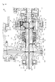
- a transmission 7 as a transmission in a work vehicle is described below with reference to FIG. 1 .
- the transmission 7 according to this embodiment is described as that mounted in a tractor as an agricultural vehicle.
- the present invention is not limited to this, and may be widely applied to vehicles in general including other agricultural vehicles, construction vehicles, industrial vehicles, and the like.
- the description is given below with the direction indicated by an arrow F in the drawings defined as a forward direction.
- the transmission 7 changes a driving force from an engine (not illustrated) as a driving source and then outputs the driving force.
- the transmission 7 includes a mission input shaft 20, a clutch mechanism 200, a belt type continuously variable transmission 40, an output shaft 170, a front wheel driving force transmission shaft 180, a PTO brake 210, a PTO input shaft 220, a rear PTO shaft 230, a mid-PTO shaft 240, and the like.
- the driving force from the engine is transmitted to the mission input shaft 20 and then is transmitted to the belt type continuously variable transmission 40 and the PTO input shaft 220 through the clutch mechanism 200.
- the driving force transmitted to the belt type continuously variable transmission 40 is changed in a stepless manner in the belt type continuously variable transmission 40 and then is transmitted to the output shaft 170 and the forward wheel driving force transmission shaft 180.
- the driving force transmitted to the output shaft 170 is transmitted to rear wheels (not illustrated) of the tractor through a final speed reducer (not illustrated), and the like.
- the driving force transmitted to the front wheel driving force transmission shaft 180 is transmitted to front wheels (not illustrated) of the tractor through a front axle (not illustrated) and the like.
- the driving force transmitted to the PTO input shaft 220 is transmitted to the rear PTO shaft 230 and the mid-PTO shaft 240 through a gear and the like.
- the speed of the tractor can be adjusted as desired through changing the transmission ratio in the belt type continuously variable transmission 40 in the transmission 7 having the configuration described above.
- An implement (a rototiller and the like for example) coupled to the rear PTO shaft 230 and an implement (a mid-mower and the like for example) coupled to the mid-PTO shaft 240 can be driven by driving forces respectively transmitted to the rear PTO shaft 230 and the mid-PTO shaft 240.
- the PTO brake 210 controls the rotation of the PTO input shaft 220.
- the belt type continuously variable transmission 40 can be applied to transmissions other than the transmission 7 according to this embodiment, and can be widely applied to transmissions that changes and then outputs the driving force from the driving source.
- the belt type continuously variable transmission 40 includes a transmission input shaft 50, an input pulley 60, a hydraulic cylinder 70, a hydraulic servo mechanism 80, a transmission shaft 90, an output pulley 100, an output member 110, a cam mechanism 120, a biasing member 130, a belt 140, a planetary gear mechanism 150, and the like.
- the transmission input shaft 50 shown in FIG. 1 and FIG. 2 is coupled to the mission input shaft 20, and transmits the driving force from the mission input shaft 20.
- the transmission input shaft 50 has an approximately column shape and is disposed with an axial direction thereof being a front-rear direction. At an intermediate part of the transmission input shaft 50 in the front-rear direction, a large diameter portion 50a having a larger diameter than the other portion is formed.
- a transmission input gear 51 is coupled to a portion of the transmission input shaft 50 around the rear end through spline fitting in such a manner as to be not relatively rotatable with respect to the transmission input shaft 50.
- the transmission input gear 51 meshes with a gear of the clutch mechanism 200 (see FIG.
- a method of coupling the transmission input gear 51 to the transmission input shaft 50 is not limited to the spline fitting, and the transmission input gear 51 and the transmission input shaft 50 can be integrally formed, for example.
- a bearing 52 fits the transmission input shaft 50 at a portion right behind the transmission input gear 51.
- a bearing 53 fits the transmission input shaft 50 at a portion more on the front side than the larger diameter portion 50a.
- the bearings 52 and 53 are respectively supported by a mission casing 8 accommodating the transmission 7 and a front casing 81 to be described later, and thus the transmission input shaft 50 is rotatably supported by the mission casing 8.
- the input pulley 60 shown in FIG. 3 is disposed on the transmission input shaft 50, and includes a pair of sheaves.
- the input pulley 60 includes an input side fixed sheave 61, an input side movable sheave 63, and the like.
- the input side fixed sheave 61 includes an approximately cylindrical shaft portion, and an annular sheave portion integrally formed at the front end of the shaft portion and having an approximately frustum shape in a side cross sectional view.
- the input side fixed sheave 61 fits on the outer side of the transmission input shaft 50 with the sheave portion disposed more on the front side than the shaft portion.
- a front surface 61a of the sheave portion of the input side fixed sheave 61 is formed as an inclined surface so that a diameter increases from the front side to the rear side.
- a through hole 61b formed through the input side fixed sheave 61 in the front-rear direction is formed on the axis of the input side fixed sheave 61.
- a small diameter portion 61c at which the diameter of the through hole 61b is smaller than the other portion is formed at the rear end portion of the through hole 61b (specifically, a portion corresponding to the shaft portion of the input side fixed sheave 61 in the axial direction).
- the transmission input shaft 50 is inserted in the through hole 61b of the input side fixed sheave 61 from the front side.
- the transmission input shaft 50 is pressed in until the front surface of the small diameter portion 61c of the through hole 61b comes into contact with the rear surface of the large diameter portion 50a of the transmission input shaft 50.
- the input side fixed sheave 61 is fixed to the transmission input shaft 50 so as to be not relatively rotatable nor slidable.
- the input side fixed sheave 61 With the input side fixed sheave 61 being thus fixed to the transmission input shaft 50 by press fitting, a manufacturing cost can be reduced compared with a case where a spline and a serration are used for the fixing. Moreover, insufficient fitting between the input side fixed sheave 61 and the transmission input shaft 50 can prevented. Thus, the transmission ratio of the belt type continuously variable transmission 40 can be prevented from changing, and the degradation of the durability of the contact surface between the belt 140 and the input side fixed sheave 61 can be prevented. Furthermore, the input side fixed sheave 61 can be positioned with respect to the transmission input shaft 50 only by the press fitting completed when the small diameter portion 61c of the through hole 61b comes into contact with the large diameter portion 50a of the transmission input shaft 50. Thus, the input side fixed sheave 61 can be positioned easier and more accurately than in a case where the input side fixed sheave 61 is fixed to the transmission input shaft 50 with a taper.
- the transmission input shaft 50 and the input side fixed sheave 61 are press fit (fit) with each other.
- any fitting method utilizing the configuration that the transmission input shaft 50 has a larger diameter than the through hole 61b, such as "shrink fitting” and “expansion fitting” may be used.
- the portion right behind the larger diameter portion 50a of the transmission input shaft 50 and the small diameter portion 61c of the input side fixed sheave 61 are press fit with each other.
- the present invention is not limited to this. Specifically, the larger diameter portion 50a of the transmission input shaft 50 and a portion right in front of the small diameter portion 61 c of the input side fixed sheave 61 may be press fit with each other.
- the small diameter portion 61c of the input side fixed sheave 61 may slide on the transmission input shaft 50 to serve as a guide in the press fitting. Furthermore, in this embodiment, the input side fixed sheave 61 has the sheave portion formed at the front end of the shaft portion. This should not be construed as a limiting sense, and the sheave portion may be formed at the rear end of the shaft portion.
- a locknut 62 is fastened to the transmission input shaft 50 at a portion right behind the input side fixed sheave 61.
- the input side fixed sheave 61 can be prevented from sliding rearward on the transmission input shaft 50, and the input side fixed sheave 61 can be surely fixed to the transmission input shaft 50.
- the input side movable sheave 63a includes an approximately cylindrical shaft portion, and an annular sheave portion integrally formed at the rear end of the shaft portion, and having an approximately frustum shape in a side cross sectional view.
- the input side movable sheave 63 fits on the outer side of the transmission input shaft 50 and is disposed more on the front side than the input side fixed sheave 61 with the sheave portion disposed more on the rear side than the shaft portion.
- a rear surface 63a of the sheave portion of the input side movable sheave 63 is formed as an inclined surface so that a diameter increases from the rear side to the front side.
- a through hole 63b formed through the input side movable sheave 63 in the front-rear direction is formed on the axis of the input side movable sheave 63.
- the transmission input shaft 50 is inserted in the through hole 63b of the input side movable sheave 63 from the rear side.
- the front surface 61a of the input side fixed sheave 61 and the rear surface 63a of the input side movable sheave 63 face each other on the transmission input shaft 50.
- a groove of the input pulley 60 is defined by the front surface 61a and the rear surface 63a.
- Sheave side grooves 63c and shaft side grooves 50b along the axial direction of the transmission input shaft 50 are respectively formed on an inner peripheral surface of the through hole 63b and an outer peripheral surface of the transmission input shaft 50.
- the sheave side grooves 63c are each formed at least from the front end (front end of the shaft portion) of the input side movable sheave 63 to an intermediate portion of the input side movable sheave 63 in the front-rear direction.
- the sheave side grooves 63c are formed at three portions in the inner peripheral surface of the through hole 63b at an equal interval in the peripheral direction
- the shaft side grooves 50b are formed at three portions in the outer peripheral surface of the transmission input shaft 50 at an equal interval in the peripheral direction.
- Steel balls 64, 64, ... are disposed in a pair of grooves facing each other.
- the input side movable sheave 63 is supported by the transmission input shaft 50 in such a manner as to be slidable in the axial direction and not to be relatively rotatable.
- Intervals between the sheave side grooves 63c and the shaft side grooves 50b are not limited to equal intervals, and the numbers of the sheave side grooves 63c and the shaft side grooves 50b are not limited to those described above.
- a through hole 63d communicating between the outer peripheral surface of the shaft portion and the inner surface of the through hole 63b is formed in the input side movable sheave 63.
- the through hole 63d is formed at a position that does not overlap the sheave side grooves 63c formed in the inner peripheral surface of the through hole 63b.
- the hydraulic cylinder 70 makes the input side movable sheave 63 slide on the transmission input shaft 50 along the axial direction of the transmission input shaft 50.
- the hydraulic cylinder 70 includes a movable side cylinder casing 71, a fixed side cylinder casing 73, and the like.
- the movable side cylinder casing 71 is a box shaped member opened at the front portion. At the center of the rear surface of the movable side cylinder casing 71, a through hole 71a is formed along the axial direction. The shaft portion of the input side movable sheave 63 is inserted in the through hole 71a.
- the movable side cylinder casing 71 is fixedly disposed on the input side movable sheave 63 by means of a fastening member such as a bolt, by welding, or by other means, with the front surface of the sheave portion of the input side movable sheave 63 being in contact with the rear surface of the movable side cylinder casing 71.
- the movable side cylinder casing 71 and the input side movable sheave 63 may be integrally formed by forging and the like.
- the fixed side cylinder casing 73 includes a box shaped portion opened at a rear portion and an annular flange integrally formed at the rear end of the box shaped portion.
- a through hole 73a is formed at the center of the front surface of the fixed side cylinder casing 73.
- the transmission input shaft 50 is inserted in the through hole 73a.
- the rear portion (flange) of the fixed side cylinder casing 73 is inserted in the movable side cylinder casing 71 from the opened side (front side) of the movable side cylinder casing 71.
- a seal member 74 is disposed between the fixed side cylinder casing 73 and the movable side cylinder casing 71.
- a bearing 72 fits on the inner side of an opened (front) side end of the movable side cylinder casing 71.
- the transmission input shaft 50 is inserted in the bearing 53 at a portion right in front of the fixed side cylinder casing 73, and is rotatably supported by the mission casing 8 through the bearing 53.
- a locknut 75 is fastened to the transmission input shaft 50 at a portion right in front of the bearing 53.
- the bearing 53 can be prevented from sliding forward, and thus the fixed side cylinder casing 73 can be prevented from sliding forward through the bearing 53.
- the bearing 53, the fixed side cylinder casing 73, the movable side cylinder casing 71, the input side movable sheave 63, the belt 140, and the input side fixed sheave 61 are disposed between the locknut 62 and the locknut 75.
- the torque applied to the members can be confined between the locknut 62 and the locknut 75.
- the hydraulic cylinder 70 is disposed on the input side movable sheave 63 of the input pulley 60.
- a hydraulic chamber 76 is formed in a space defined by the input side movable sheave 63, the movable side cylinder casing 71, the fixed side cylinder casing 73, and the transmission input shaft 50.
- the hydraulic servo mechanism 80 controls the operation of the input side movable sheave 63 through the hydraulic cylinder 70.
- the hydraulic servo mechanism 80 includes the front casing 81, a serve spool 83, a feedback spool 84, a spool spring 85, and the like.
- the front casing 81 includes an approximately rectangular main body and a disk shaped flange formed integrally at the rear end of the main body.
- a valve chest 81a, a bearing hole 81b, a hydraulic oil port 81c, a communication oil passage 81d, a lubricant port 81, and the like are formed.
- the valve chest 81a is a through hole having a circular cross-sectional shape and formed to communicate between the front surface and the rear surface of the front casing 81.
- the valve chest 81 a is formed with the axial direction thereof being the front-rear direction.
- the valve chest 81a is formed at a position overlapping the input side movable sheave 63 of the input pulley 60 in the front view, that is, the position facing the input side movable sheave 63.
- the bearing hole 81b is a through hole having a circular cross-sectional shape and formed to communicate between the front surface and the rear surface of the front casing 81.
- the bearing hole 81b is formed with the axial direction thereof being the front-rear direction.
- the front end portion of the transmission input shaft 50 is inserted in the bearing hole 81b from the rear side.
- the front end portion of the bearing hole 81b is closed by a plug 82.
- the hydraulic oil port 81c is a through hole communicating between the side surface of the main body of the front casing 81 and the valve chest 81a. More specifically, the hydraulic oil port 81c communicates between the side surface of the main body of the front casing 81 and an approximately center portion of the valve chest 81a in the axial direction.
- the hydraulic oil port 81c is coupled to an unillustrated hydraulic oil pump through a pipe and the like.
- the hydraulic oil port 81c may have any shape and size as long as the port communicates between the outside of the front casing 81 and the valve chest 81a.
- the communication oil passage 81d is formed to communicate between the valve chest 81a and the bearing hole 81d, more specifically between a portion of the valve chest 81a around the rear end and a portion of the bearing hole 81b around the rear end.
- the lubricant port 81e is a through hole formed to communicate between the side surface of the main body of the front casing 81 and the bearing hole 81b. More specifically, the lubricant port 81e communicates between the side surface of the main body of the front casing 81 and an approximately center portion of the bearing hole 81b in the axial direction. The lubricant port 81e is coupled to an unillustrated lubricant pump through a pipe and the like.
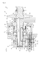
- the servo spool 83 shown in FIG. 3 and FIG. 4 switches an oil passage in the hydraulic servo mechanism 80.
- the servo spool 83 has an approximately column shape with a disk shaped flange integrally formed at the rear end.
- the servo spool 83 is disposed with the axial direction thereof being the front-rear direction.
- a sliding hole 83a, a first groove 83b, a second groove 83c, a first through hole 83d, a second through hole 83e, a discharge oil passage 83f, and the like are formed.
- the sliding hole 83a is hole having a circular cross-sectional shape and formed from the rear end to a portion around the front end of the servo spool 83 on the axis of the servo spool 83.
- the first groove 83b is formed along the outer peripheral surface of the servo spool 83 at an approximately center portion of the servo spool 83 in the axial direction.
- the first groove 83b is formed to be long in the axial direction of the servo spool 83 so that, even in a case where the servo spool 83 slides along the axial direction relative to the valve chest 81a of the front casing 81, the first groove 83b always faces the hydraulic oil port 81c regardless of the slid position of the servo spool 83.
- the second groove 83c is formed at a portion more on the rear side than the first groove 83b of the servo spool 83 along the outer periphery of the servo spool 83.
- the second groove 83c is formed to be long in the axial direction of the servo spool 83 so that, even in a case where the servo spool 83 slides along the axial direction relative to the valve chest 81a of the front casing 81, the second groove 83c always faces the communication oil passage 81d regardless of the slid position of the servo spool 83.
- the first through hole 83d has an axial direction orthogonal to the axis of the servo spool 83 and is formed to communicate between the first groove 83b and the sliding hole 83a.
- the second through hole 83e has an axial direction orthogonal to the axis of the servo spool 83 and is formed to communicate between the second groove 83c and the sliding hole 83a.
- the discharge oil passage 83f is formed to communicate between the rear end of the servo spool 83 and the sliding hole 83a. More specifically, the discharge oil passage 83f communicates between the rear end of the servo spool 83 and a portion of the sliding hole 83a more on the rear side than the portion facing the second groove 83c.
- the outer diameter of the servo spool 83 is set to be approximately the same with the inner diameter of the valve chest 81 a of the front casing 81.
- the servo spool 83 is slidably inserted in the valve chest 81 a of the front casing 81 from the rear side.
- the diameter of the flange of the servo spool 83 is set to be larger than the diameter of the valve chest 81 a of the front casing 81.
- the feedback spool 84 switches an oil passage in the hydraulic servo mechanism 80.
- the feedback spool 84 has an approximately column shape.
- the feedback spool 84 is disposed with the axial direction being the front-rear direction.
- a discharge oil passage 84a, a communication groove 84b, and the like are formed in the feedback spool 84.
- the discharge oil passage 84a is formed on the axis of the feedback spool 84 to communicate between the front and rear ends of the feedback spool 84.
- the communication groove 84b is formed along the outer peripheral surface of the feedback spool 84 at an approximately center portion of the feedback spool 84 in the axial direction.
- the outer diameter of the feedback spool 84 is set to be approximately the same with the inner diameter of the sliding hole 83a of the servo spool 83.
- the feedback spool 84 is slidably inserted in the sliding hole 83a of the servo spool 83.
- the feedback spool 84 is slidable in the front-rear direction relative to the servo spool 83.
- the spool spring 85 biases the feedback spool 84 toward the rear side.
- the spool spring 85 is formed of a compression coil spring.
- the spool spring 85 is disposed in the sliding hole 83a of the servo spool 83 and constantly biases the feedback spool 84 toward the rear side (toward the input side movable sheave 63).
- the biasing member is not limited to the compressed coil spring (spool spring 85) and any configuration may be employed as long as the feedback spool 84 can be biased toward the rear side.
- the rear end of the feedback spool 84 is constantly in contact with the bearing 72 (more specifically, an inner ring of the bearing 72) of the movable side cylinder casing 71 fixedly disposed to the input side movable sheave 63.
- the feedback spool 84 contacts the movable side cylinder casing 71 not directly but with the bearing 72 disposed in between. Accordingly, the feedback spool 84 and the movable side cylinder casing 71 can be prevented from wearing by the friction. Specifically, the outer ring of the bearing 53 contacts the movable side cylinder casing 71, and the inner ring of the bearing 53 contacts the feedback spool 84. Thus, the bearing 72 reduces the friction between the feedback spool 84 and the movable side cylinder casing 71.
- the feedback spool 84 contacts the movable side cylinder casing 71 with the bearing 72 disposed in between.
- the present invention is not limited to this.
- the feedback spool 84 may contact the input side movable sheave 63 with the bearing 72 disposed in between, or directly contact the input side movable sheave 63 without the bearing 72 disposed in between.
- a member disposed between the feedback spool 84 and the movable side cylinder casing 71 is not limited to the bearing 72, and may be any member that can reduce the friction between the feedback spool 84 and the movable side cylinder casing 71 (a member having the friction reduced by surface finishing, for example).
- a first groove 50c, a second groove 50d, an operation groove 50e, a hydraulic oil passage 50f, a lubricant passage 50g, and a distribution oil passage 50h are formed.
- the first groove 50c is formed along the outer periphery of the transmission input shaft 50 at a portion of the transmission input shaft 50 around the front end portion in the axial direction. More specifically, the first groove 50c is formed at an axial direction position facing the communication oil passage 81d formed in the front casing 81 when the transmission input shaft 50 is inserted in the bearing hole 81b of the front casing 81.
- the second groove 50d is formed along the outer periphery of the transmission input shaft 50 at a portion around the front end of the transmission input shaft 50 in the axial direction and more on the front side than the first groove 50c.
- the second groove 50d is formed at an axial direction position facing the lubricant port 81e formed in the front casing 81 when the transmission input shaft 50 is inserted in the bearing hole 81b of the front casing 81.
- the operation groove 50e is formed in a part of the outer peripheral surface of the transmission input shaft 50 at an intermediate portion of the transmission input shaft 50 in the axial direction. More specifically, the operation groove 50e is formed at an axial direction position facing the through hole 63d formed in the input side movable sheave 63 when the input side movable sheave 63 is supported by the transmission input shaft 50.
- the operation groove 50e is formed to be long in the axial direction of the transmission shaft 50 so that, even in a case where the input side movable sheave 63 slides along the axial direction relative to the transmission shaft 50, the operation groove 50e always faces the through hole 63d regardless of the slid position of the movable sheave.
- the hydraulic oil passage 50f is a hole formed from the front end of the transmission input shaft 50 to approximately the same position as the operation shaft 50e in the axial direction.
- the front end portion of the hydraulic oil passage 50f is closed by a plug 54.
- the hydraulic oil passage 50f communicates with the first groove 50c at a portion around the front end portion and with the operation groove 50e at a portion around the rear end portion.
- the lubricant passage 50g is a hole formed from the front end of the transmission input shaft 50 to approximately the same position as the rear end portion of the large diameter portion 50a in the axial direction.
- the front end portion of the lubricant passage 50g is closed by a plug 55.
- the lubricant passage 50g communicates with the second groove 50d at a portion around the front end portion.
- the distribution oil passage 50h is a through hole having an axial direction orthogonal to the axis of the transmission input shaft 50, and formed to communicate between the outer peripheral surface of the transmission input shaft 50 and the lubricant passage 50g.
- the distribution oil passage 50h communicates between the a portion of the outer peripheral surface of the large diameter portion 50a of the transmission shaft 50 around the front surface 61a of the sheave portion of the input side fixed sheave 61 fixed to the transmission input shaft 50 and the lubricant passage 50g.
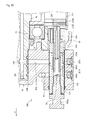
- the input side movable sheave 63 and the movable side cylinder casing 71 fixedly disposed to the input side movable sheave 63 have slid forward to a position at which the front end of the shaft portion of the input side movable sheave 63 contacts the fixed side cylinder casing 73.
- the feedback spool 84 that contacts the bearing 72 fixed to the movable side cylinder casing 71 from the front side is maintained at a state of being pressed to a predetermined position relative to the sliding hole 83a of the servo spool 83 against the biasing force of the spool spring 85.
- the "predetermined position" of the feedback spool 84 is a relative position to the servo spool 83. More specifically, the predetermined position is a position at which the outer peripheral surface of the feedback spool 84 (more specifically, a portion of the outer peripheral surface more on the front side than the communication groove 84b) closes the first through hole 83d of the servo spool 83, and the outer peripheral surface of the feedback spool 84 (more specifically, a portion of the outer peripheral surface more on the rear side than the communication groove 84b) closes the discharge oil passage 83f of the servo spool 83.
- the hydraulic oil pumped from the hydraulic oil pump is supplied to the first groove 83b of the servo spool 83 through the hydraulic oil port 81c of the front casing 81.
- the first through hole 83d communicating between the first groove 83b and the sliding hole 83a is closed by the outer peripheral surface of the feedback spool 84.
- the hydraulic oil supplied from the hydraulic oil pump is blocked by the feedback spool 84, and thus is not supplied to the hydraulic chamber 76 of the hydraulic cylinder 70.
- the input side movable sheave 63 is biased toward the front side by a tensile force of the belt 140 to be described later wound around the input pulley 60.
- the input side movable sheave 63 and the movable side cylinder casing 71 are maintained at the state after sliding forward.
- the feedback spool 84 is in contact with the bearing 72 and thus cannot slide rearward.
- the feedback spool 84 slides forward relative to the servo spool 83.
- the communication hole 84b of the feedback spool 84 faces the first through hole 83d and the second through hole 83e of the servo spool 83.
- the hydraulic oil supplied to the hydraulic oil port 81c from the hydraulic oil pump is supplied to the communication oil passage 81d through the first groove 83b, the first through hole 83d, the communication groove 84b, the second groove 83c, and the second through hole 83e.
- the hydraulic oil supplied to the communication oil passage 81d is further supplied to the hydraulic chamber 76 through the first groove 50c, the hydraulic oil passage 50f, and the operation groove 50e of the transmission input shaft 50, and the through hole 63d of the input side movable sheave 63.
- the pressure in the hydraulic chamber 76 rises, and the input side movable sheave 63 and the cylinder casing 71 are biased toward the rear side by the pressure.
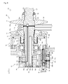
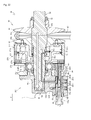
- the input side movable sheave 63 and the cylinder casing 71 thus biased toward the rear side by the pressure of the hydraulic oil slide rearward against the biasing force toward the front side produced by the tensile force of the belt 140 (see FIG. 6 ).
- the feedback spool 84 slides along with the input side movable sheave 63 and the movable side cylinder casing 71 so that the oil passage in communication with the hydraulic chamber 76 is switched, and thus the input side movable sheave 63 and the movable side cylinder casing 71 can be maintained at positions corresponding to the slid position of the servo spool 83.
- the feedback spool 84 While the servo spool 83 slides forward, the feedback spool 84 maintained at a state of being in contact with the bearing 72, because the feedback spool 84 is biased towards the bearing 72 by the spool spring 85. Thus, the feedback spool 84 slides rearward relative to the servo spool 83. Thus, the communication groove 84b of the feedback spool 84 faces the discharge oil passage 83f of the servo spool 83, and thus the hydraulic oil can flow to the discharge oil passage 83f through the second groove 83c and the second through hole 83e.
- the tensile force of the belt 140 biases the input side movable sheave 63 and the movable side cylinder casing 71 toward the front side.
- the hydraulic oil in the hydraulic chamber 76 of the hydraulic cylinder 70 is pushed out by the input side movable sheave 63 and the movable side cylinder casing 71.
- the hydraulic oil passes through the through hole 63d of the input side movable sheave 63, the operation groove 50e, the hydraulic oil passage 50f, and the first groove 50c of the transmission input shaft 50, the communication oil passage 81d, the second groove 83c, and the second through hole 83e of the servo spool 83, the communication groove 84b of the feedback spool 84, and the discharge oil passage 83f of the servo spool 83, to be discharged to the rear side from the rear end of the servo spool 83.
- the bearing 72 fixed to the movable cylinder casing 71 can be lubricated by the hydraulic oil discharged from the rear end of the servo spool 83.
- the first through hole 83d of the servo spool 83 is still closed by the outer periphery surface of the feedback spool 84.
- the hydraulic oil from the hydraulic oil pump is not supplied to the hydraulic chamber 76 of the hydraulic cylinder 70.
- the input side movable sheave 63 can be slid to a desired position.
- the feedback spool 84 that slides along with the input side movable sheave 63 can maintain the input side movable sheave 63 at the desired slid position.
- sliding of the input side movable sheave 63 is caused by the hydraulic servo mechanism 80.
- the present invention is not limited to this.
- a configuration in which the sliding of an output side movable sheave 103 of the output pulley 100 described later is caused by the hydraulic servo mechanism 80 can be employed.
- the hydraulic oil supplied to the hydraulic chamber 76 of the hydraulic cylinder 70 as described above leaks into the shaft side grooves 50b of the transmission input shaft 50 and the sheave side grooves 63c of the input side movable sheave 63 through a gap between the front end of the shaft portion of the input side movable sheave 63 and the fixed side cylinder casing 73.
- the steel balls 64, 64, ... disposed in the shaft side grooves 50b and the sheave side grooves 63c are lubricated by the hydraulic oil.
- the hydraulic oil supplied to the hydraulic chamber 76 of the hydraulic cylinder 70 leaks to the rear side of the sheave side groove 63c through a gap between the front end of the shaft portion of the input side movable sheave 63 and the fixed side cylinder casing 73, and the gap between the input side movable sheave 63 and the transmission input shaft 50.
- the contact surface (sliding surface) between the input side movable sheave 63 and the transmission input shaft 50 is lubricated by the hydraulic oil.
- a fixed oil passage is not provided in the transmission input shaft 50, and the hydraulic oil is supplied through the gap between the input side movable sheave 63 and the transmission input shaft 50.
- the input side movable sheave 63 can be appropriately lubricated regardless of the slid position of the input side movable sheave 63.
- the rear surface 63a of the sheave portion of the input side movable sheave 63 and the contact surface of belt 140 to be described later are lubricated by the he hydraulic oil leaked to the rear side of the input side movable sheave 63 as described above.
- the hydraulic oil leaked to the sliding hole 83a of the servo spool 83 through a gap between the servo spool 83 and the feedback spool 84 is discharged from the rear end of the feedback spool 84 through the discharge oil passage 84a of the feedback spool 84.
- the contact surface between the feedback spool 84 and the bearing 72 is lubricated by the hydraulic oil thus discharged.
- the hydraulic oil pumped from the lubricant pump to be supplied to the lubricant port 81e of the front casing 81 is supplied to the outer peripheral surface of the transmission input shaft 50 (around the front surface 61a of the sheave portion of the input side fixed sheave 61) through the second groove 50d, the lubricant passage 50g, and the distribution oil passage 50h of the transmission input shaft 50.
- the contact surface between the front surface 61a of the sheave portion of the input side fixed sheave 61 and the belt 140 to be described later are lubricated by the hydraulic oil thus supplied.
- the oil passage (the lubricant port 81e, the second groove 50d, as well as the lubricant passage 50g, and the distribution oil passage 50h of the transmission input shaft 50, and the like) for supplying the hydraulic oil for lubricating the front surface 61a of the input side fixed sheave 61 is formed for the input side fixed sheave 61 that does not slide relative to the transmission input shaft 50.
- the input side fixed sheave 61 can be appropriately lubricated.
- the transmission shaft 90 shown in FIG. 1 and FIG. 10 transmits the driving force from the transmission input shaft 50.
- the transmission shaft 90 has an approximately column shape and is disposed with its axial direction being the front-rear direction.
- a large diameter portion 90a having a larger diameter than the other portion is formed around the front end.
- a bearing 91 fits the transmission shaft 90 at a portion more on the front side than the large diameter portion 90a. With the bearing 91 supported by the mission casing 8, the transmission shaft 90 is rotatably supported by the mission casing 8.
- the output pulley 100 shown in FIG. 11 is disposed on the transmission shaft 90 and includes a pair of sheaves.
- the output pulley 100 includes an output side fixed sheave 101, an output side movable sheave 103, and the like.
- the output side fixed sheave 101 and the input side fixed sheave 61 are formed by the same material and have the same shape.
- the input side fixed sheave 101 includes an approximately cylindrical shaft portion, and an annular sheave portion integrally formed at the rear end of the shaft portion and having an approximately frustum shape in a side cross sectional view.
- the input side fixed sheave 101 is fit on the outer side of the transmission shaft 90 with the sheave portion disposed more on the front side than the shaft portion.
- a rear surface 101a of the sheave portion of the output side fixed sheave 101 is formed as an inclined surface so that a diameter increases from the rear side to the front side.
- a through hole 101b formed through the input side fixed sheave 101 in the front-rear direction is formed on the axis of the output side fixed sheave 101.
- a small diameter portion 101c at which the diameter of the through hole 101b is smaller than the other portion is formed at the front end portion of the through hole 101b (specifically, a portion corresponding to the shaft portion of the output side fixed sheave 101 in the axial direction).
- the transmission shaft 90 is inserted in the through hole 101b of the output side fixed sheave 101 from the rear side. The transmission shaft 90 is pressed in until the rear surface of the small diameter portion 101c of the through hole 101b comes into contact with the front surface of the large diameter portion 90a of the transmission shaft 90.
- the output side fixed sheave 101 is fixed to the transmission shaft 90 so as to be not relatively rotatable nor slidable.
- the output side fixed sheave 101 With the output side fixed sheave 101 being thus fixed to the transmission shaft 90 by press fitting, a manufacturing cost can be reduced compared with a case where a spline and a serration are used for the fixing. Moreover, insufficient fitting between the output side fixed sheave 101 and the transmission shaft 90 can be prevented. Thus, the transmission ratio of the belt type continuously variable transmission 40 can be prevented from changing, and the degradation of the durability of the contact surface between the belt 140 and the output side fixed sheave 101 can be prevented. Furthermore, the output side fixed sheave 101 can be positioned with respect to the transmission shaft 90 only by the press fitting completed when the small diameter portion 101c of the through hole 101b comes into contact with the large diameter portion 90a of the transmission shaft 90. Thus, the output side fixed sheave 101 can be positioned easier and more accurately than in a case where the output side fixed sheave 101 is fixed to the transmission shaft 90 with a taper.
- the transmission shaft 90 and the output side fixed sheave 101 are press fit (fit) with each other.
- any fitting method utilizing the configuration that the transmission shaft 90 has a larger diameter than the through hole 101b of the output side fixed sheave 101 such as "shrink fitting” and “expansion fitting” may be used.
- the portion right in front of the larger diameter portion 90a of the transmission shaft 90 and the small diameter portion 101c of the output side fixed sheave 101 are press fit with each other.
- the present invention is not limited to this.
- the larger diameter portion 90a of the transmission shaft 90 and a portion right behind the small diameter portion 101 c of the output side fixed sheave 101 may be press fit with each other.
- the small diameter portion 101c of the output side fixed sheave 101 may slide on the transmission shaft 90 to serve as a guide in the press fitting.
- the transmission shaft 90 is inserted in the bearing 91 described above at a portion right in front of the output side fixed sheave 101, and is rotatably supported by the mission casing 8 through the bearing 91.
- a locknut 102 is fastened to the transmission shaft 90 at a portion right in front of the bearing 91.
- the output side movable sheave 103 and the input side movable sheave 63 are formed of the same material and have the same shape.
- the output side movable sheave 103a includes an approximately cylindrical shaft portion and an annular sheave portion integrally formed at the rear end of the shaft portion, and having an approximately frustum shape in a side cross sectional view.
- the output side movable sheave 103 is fit on the outer side of the transmission shaft 90 and disposed more on the rear side than the output side fixed sheave 101 with the sheave portion disposed more on the front side than the shaft portion.
- a front surface 103a of the sheave portion of the output side fixed sheave 103 is formed as an inclined surface so that a diameter increases from the front side to the rear side.
- a through hole 103b formed through the output side movable sheave 103 in the front-rear direction is formed on the axis of the output side movable sheave 103.
- the transmission shaft 90 is inserted in the through hole 103b of the output side movable sheave 103 from the front side.
- the rear surface 101a of the output side fixed sheave 101 and the front surface 103a of the output side movable sheave 103 face each other on the transmission shaft 90.
- a groove of the output pulley 100 is defined by the rear surface 101a and the front surface 103a.
- Sheave side grooves 103c and shaft side grooves 90b along the axial direction of the transmission shaft 90 are respectively formed on an inner peripheral surface of the through hole 103b and an outer peripheral surface of the transmission shaft 90.
- the sheave side grooves 103c are each formed at least from the rear end (rear end of the shaft portion) of the output side movable sheave 103 to an intermediate portion in the front-rear direction of the output side movable sheave 103.
- the sheave side grooves 103c are formed at three portions in the inner peripheral surface of the through hole 103b at an equal interval in the peripheral direction
- the shaft side grooves 90b are formed at three portions in the outer peripheral surface of the transmission shaft 90 at an equal interval in the peripheral direction.
- the output side movable sheave 103 is supported by the transmission shaft 90 in such a manner as to be slidable in the axial direction and not to be relatively rotatable.
- Intervals between the sheave side grooves 103c and the shaft side grooves 90b are not limited to equal intervals, and the numbers of the sheave side grooves 103c and the shaft side grooves 90b are not limited to those described above.
- the through hole 103d communicating between the outer peripheral surface of the shaft portion and the inner peripheral surface of the through hole 103b is formed in the output side movable sheave 103.
- the through hole 103d is formed at a position that does not overlap the sheave side grooves 103c formed in the inner peripheral surface of the through hole 103b.
- the same members are commonly used for the input side fixed sheave 61 and the input side movable sheave 63 of the input pulley 60, and the output side fixed sheave 101 and the output side movable sheave 103 of the output pulley 100.
- the number of component types can be reduced and thus, the component cost can be reduced.
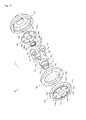
- the output member 110 transmits the driving force from the cam mechanism 120 to the planetary gear mechanism 150.
- the output member 110 includes a shaft portion having an approximately cylindrical shape and an annular flange integrally formed at the front end of the shaft portion.
- a cylindrical outer guide portion 110a is formed on the front end side of the output member 110.
- the outer guide portion 110a is disposed with the axial direction thereof extending in the front-rear direction, and has a bottomed tubular shape with a front side opened.
- a through hole is formed in the axial direction.
- a spline portion 110b is formed on an inner peripheral surface of the through hole.
- the output member 110 is disposed at a portion more on the rear side than the output pulley 100 with the transmission shaft 90 inserted in the through hole of the output member 110.
- the cam mechanism 120 allows the transmission of a torque between the output pulley 100 and the output member 110.
- the cam mechanism 120 includes a first cam 121, a second cam 122, and the like.
- the first cam 121 has an approximately cylindrical shape.
- the first cam 121 is disposed with its axial direction extending in the front-rear direction, and its axis matching the axis of the transmission shaft 90.
- a through hole 121a having a predetermined inner diameter is formed on an axis of the first cam 121.
- the inner diameter of the through hole 121a of the first cam 121 is set to be approximately the same as the inner diameter of the outer guide member 110a of the output member 110.
- On the front surface of the first cam 121 a flat surface orthogonal to the axial direction is formed, and on the rear surface of the first cam 121, a plurality of surfaces inclined by a predetermined angle with respect to the surface orthogonal to the axial direction and the like are formed.
- the shaft portion of the output side movable sheave 103 is inserted in the through hole 121 a of the first cam 121 from the front side.
- the first cam 121 is fixedly disposed on the output side movable sheave 103 by means of a fastening member such as a bolt, by welding, or by other means, with the rear surface of the output side movable sheave 103 being in contact with the front surface of the first cam 121.
- the first cam 121 and the output side movable sheave 103 may be integrally formed by forging and the like.
- the second cam 122 and the first cam 121 are formed by the same material and have the same shape. Specifically, the second cam 122 is disposed with its axial direction extending in the front-rear direction, and with its axis matching the axis of the transmission shaft 90. A through hole 122a having a predetermined inner diameter is formed on the axis of the second cam 122. The inner diameter of the through hole 122a of the second cam 122 is set to be approximately the same as the inner diameter of the outer guide member 110a of the output member 110.
- the transmission shaft 90 is inserted in the through hole 122a of the second cam 122 from the front side.
- the second cam 122 is fixedly disposed on the output member 110 by means of a fastening member such as a bolt, by welding, or by other means, with the front surface of the output member 110 being in contact with the rear surface of the second cam 122.
- a fastening member such as a bolt
- the front surface of the output member 110 being in contact with the rear surface of the second cam 122.
- the rear surface of the first cam 121 and the front surface of the second cam 122 face each other.
- the second cam 122 and the output member 110 may be integrally formed by forging and the like.
- the biasing member 130 biases the output side movable sheave 103 toward the front side.
- the biasing member 130 is disposed in the outer guide member 110a of the output member 110 and includes a plurality of disc springs 131, 131, ... arranged in the axial direction.
- the rear end of the biasing member 130 comes into contact with the output member 110, while the front end of the biasing member 130 (the forward-most disc spring 131) comes into contact with the rear end of the output side movable sheave 103 with an inner guide member 132 disposed in between.
- the inner guide member 132 includes an approximately cylindrical cylinder portion 132a and an annular spring bearing 132b integrally formed at the front end of the cylinder portion 132a.
- the inner diameter of the cylinder portion 132a is set to be approximately the same with the outer diameter of the transmission shaft 90, and the axial direction length of the cylinder portion 132a is set to a predetermined length.
- the spring bearing 132b is formed to be orthogonal to the axial direction.
- the output side movable sheave 103 is biased toward the front side, that is, in the direction toward the output side fixed sheave 101, by the biasing force of the biasing member 130.
- the inner diameter of the guide member 110a of the output member 110 is set to be approximately the same as the inner diameter of the biasing member 130 (disc springs 131, 131, ).
- the outer diameter of the cylinder portion 132a of the inner guide member 132 is set to be approximately the same as the inner diameter of the biasing member 130 (disc springs 131, 131, ).
- ones of the disc springs 131 of the biasing member 130 disposed on the rear side are guided without having their axes misaligned, by the outer guide member 110a of the output member 110 (more specifically, by the inner peripheral surfaces of the outer guide member 110a of the output member 110 and the second cam 122), and ones of the disc springs 131 of the biasing member 130 disposed on the front side are guided without having their axes misaligned, by the cylinder portion 132a of the inner guide member 132.
- the misalignment of the axes of the plurality of disc springs 131, 131, ... is thus prevented. Accordingly, the output side movable sheave 103 can be stably biased.
- the cylinder portion 132a of the inner guide member 132 extends rearward in the axial direction to a position overlapping the inner peripheral surface of the second cam 122.
- the biasing member 130 being formed of the plurality of disc springs 131, 131, ... as in this embodiment, the biasing member 130 can have a shorter length in the axial direction and thus can be more compact than in a case where a coil spring is used as the biasing member.
- the belt 140 shown in FIG. 2 and FIG. 10 is wound around the grooves of the input pulley 60 and the output pulley 100.
- the belt 140 transmits the driving force from the input pulley 60 to the output pulley 100.
- the belt 140 is a metal belt including a band formed of stacked metallic thin plates and a metallic element.
- the present invention is not limited to this, and a rubber, chain, or resin belt may be used as the belt 140.
- the belt 140 wound around the groove of the input pulley 60 is clamped by the input pulley 60 with the input side movable sheave 63 pressed toward the input side fixed sheave 61 with a predetermined strength by the hydraulic cylinder 70.
- the belt 140 wound around the groove of the output pulley 100 is clamped by the output pulley 100 with the output side movable sheave 103 pressed toward the output side fixed sheave 101 with a predetermined strength by the biasing force of the biasing member 130 and the like.
- the planetary gear mechanism 150 shown in FIG. 12 and FIG. 13 combines and outputs two driving forces.
- the planetary gear mechanism includes a sun gear 151, a ring gear 152, a carrier gear 153, planetary shafts 155, 155, ..., coupling shafts 156, 156, ..., planetary gears 157, 157, ..., a supporting member 159, a planetary output member 163, and the like.
- FIG. 13 detail shapes of teeth and splines formed in the gears are omitted.
- the sun gear 151 is a gear having a spline portion 151a formed on an outer periphery of the front end of the approximately cylindrical shaft portion, and teeth 151b formed on an outer periphery of the rear end portion of the cylindrical shaft portion that is separated from the spline portion 151a by a predetermined distance.
- a through hole 151c is formed through the sun gear 151 in the front-rear direction.
- the transmission shaft 90 is inserted in the through hole 151c of the sun gear 151 from the front side, and the sun gear 151 is relatively rotatably supported by the transmission shaft 90.
- the spline portion 151a of the sun gear 151 meshes with the spline portion 110b of the output member 110, and the sun gear 151 integrally rotates with the output member 110.
- the ring gear 152 is a gear having teeth 152a formed on an inner peripheral surface of an annular member.
- the transmission shaft 90 is inserted in the ring gear 152 from the front side and the teeth 152a of the ring gear 152 are disposed at a position facing the teeth 151b of the sun gear 151.
- the carrier gear 153 is a gear having teeth 153a formed on an outer peripheral surface of an approximately disk shaped member.
- a through hole 153b is formed through the carrier gear 153 in the front-rear direction.
- three through holes 153c, 153c, ... each having a predetermined inner diameter are formed through the carrier gear 153 in the front-rear direction at an equal interval.
- three through holes 153d, 153d, ... each having a predetermined inner diameter are formed through the carrier gear 153 in the front-rear direction at an equal interval.
- the through holes 153c, 153c, ... and the through holes 153d, 153d, ... are alternately arranged on the single periphery.
- the sun gear 151 supported by the transmission shaft 90 is inserted in the through hole 153b of the carrier gear 153.
- the carrier gear 153 is relatively rotatably supported at a cylinder portion (intermediate portion in the front-rear direction) of the sun gear 151 with a needle bearing 154 provided in between.
- the teeth 153a of the carrier gear 153 mesh with the gear of the clutch mechanism 200 disposed on the mission input shaft 20.
- the driving force from the mission input shaft 20 can be transmitted through the clutch mechanism 200.
- the planetary shafts 155, 155, ... have an approximately column shape.
- the other ends (rear ends) of the planetary shafts 155, 155, ... extend rearward.
- the coupling shafts 156, 156, ... have an approximately column shape.
- the coupling shafts 156, 156, ... have one ends (front end) fit in the respective through holes 153d, 153d, ... of the carrier gear 153, and thus are fixed to the carrier gear 153.
- the other ends (rear ends) of the coupling shafts 156, 156, ... extend rearward.
- the planetary gears 157, 157, ... are three gears that mesh with the teeth 151b of the sun gear 151 and the teeth 152a of the ring gear 152.
- a through hole 157a is formed through the planetary gear 157 in the front-rear direction.
- the planetary shafts 155, 155, ... fixed to the carrier gear 153 are respectively inserted into the through holes 157a, 157a, ... of the planetary gears 157, 157, ....
- the planetary gears 157, 157, ... are relatively rotatably supported by the planetary shafts 155, 155, ... with needle bearings 158, 158, .., provided in between.
- the supporting member 159 includes an approximately cylindrical shaft portion and an annular flange integrally formed at the front end of the cylinder portion.
- a through hole 159a is formed through the supporting member 159 in the front-rear direction.
- three through holes 159b, 159b, ... each having a predetermined inner diameter are formed through the flange of the supporting member 159 in the front-rear direction at an equal interval.
- each having a predetermined inner diameter are formed through the flange of the supporting member 159 in the front-rear direction at an equal interval.
- the through holes 159b, 159b, ... and the through holes 159c, 159c, ... are alternately arranged on the single periphery.
- the transmission shaft 90 is inserted in the through hole 159a of the supporting member 159.
- the supporting member 159 is relatively rotatably supported by the transmission shaft 90 with a bearing 160 provided in between at a portion behind the planetary gears 157, 157, ....
- a locknut 161 is fastened to the transmission shaft 90.
- the bearing 160 can be prevented from sliding rearward.
- the supporting member 159 is coupled to the carrier gear 153 in an integrally rotatable manner through the planetary shafts 155, 155, ... and the coupling shafts 156, 156, ....
- a communication member 162 having an annular shape is disposed between the through hole 159a of the supporting member 159 (more specifically, a portion corresponding to the flange of the supporting member 159) and the transmission shaft 90.
- the planetary output member 163 is a box shaped member opened at the front portion.
- a through hole is formed at the center of the rear surface of the planetary output member 163, and a spline portion 163a is formed in the through hole.
- the planetary output member 163 is disposed to cover the rear end portion of the transmission shaft 90 and the supporting member 159 from the rear side of the transmission shaft 90.
- a portion around the center of the planetary output member 163 in the front-rear direction is relatively rotatably supported to the transmission shaft 90 with a bearing 164 provided in between.
- the front end of the planetary output member 163 is fastened to the ring gear with bolts 165, 165, ... and is integrally rotatably coupled to the ring gear 152.
- the planetary output member 163 and the ring gear 152 may be integrally formed by forging and the like.
- An output shaft 170 is spline fit to the spline portion 163a of the planetary output member 163.
- the driving force from the planetary output member 163 is transmittable to rear wheels (not shown) and the front wheel driving force transmission shaft 180 of the tractor through the output shaft 170.
- a lubricant passage 90c In the transmission shaft 90, a lubricant passage 90c, a distribution oil passage 90d, a cam portion oil passage 90e, a carrier distribution oil passage 90f, and a planetary distribution oil passage 90g are formed.
- the lubricant passage 90c is a hole formed from the front end to a portion around the rear end in the transmission shaft 90.
- the lubricant passage 90c is coupled to an unillustrated lubricant pump through a pipe and the like.
- the distribution oil passage 90d is a through hole having an axial direction in a direction orthogonal to the axis of the transmission shaft 90, and formed to communicate between the outer peripheral surface of the transmission shaft 90 and the lubricant passage 90c. More specifically, the distribution oil passage 90d communicates between a portion of the outer peripheral surface of the large diameter portion 90a of the transmission shaft 90 around the rear surface 101a of the sheave portion of the output side fixed sheave 101 fixed to the transmission shaft 90 and the lubricant passage 90.
- the cam portion oil passage 90e is a through hole that communicates between a portion of the outer peripheral surface of the transmission shaft 90 facing the through hole 103d formed in the output side movable sheave 103 and the lubricant passage 90c.
- the carrier distribution oil passage 90f is a through hole having an axial direction in a direction orthogonal to the axis of the transmission shaft 90, and formed to communicate between the outer peripheral surface of the transmission shaft 90 and the lubricant passage 90c. More specifically, the carrier distribution oil passage 90f communicates between a portion of the outer peripheral surface of the transmission shaft 90 facing the shaft portion (intermediate portion in the front-rear direction) of the sun gear 151 and the lubricant passage 90c.
- the planetary distribution oil passage 90g is a through hole having an axial direction in a direction orthogonal to the axis of the transmission shaft 90, and formed to communicate between the outer peripheral surface of the transmission shaft 90 and the lubricant passage 90c. More specifically, the planetary distribution oil passage 90g communicates between a portion of the outer peripheral surface of the transmission shaft 90 facing the communication member 162 and the lubricant passage 90c.
- a distribution oil passage 151 d is formed in the sun gear 151.
- the distribution oil passage 151d is a through hole having an axial direction in a direction orthogonal to the axis of the transmission shaft 90, and formed to communicate between the outer peripheral surface of the sun gear 151 and the through hole 151c. More specifically, the distribution oil passage 151d communicates between the outer peripheral surface of the shaft portion (intermediate portion in the front-rear direction) of the sun gear 151 and a portion of the transmission shaft 90 at the same position as the carrier distribution oil passage 90f in the axial direction.
- a distribution oil passage 162a is formed in the communication member 162.
- the distribution oil passage 162a is an oil passage defined by a groove formed in the inner peripheral surface of the communication member 162 and a through hole having an axial direction in a direction orthogonal to the axis of the communication member 162 and formed to communicate between the groove and the outer peripheral surface of the communication member 162,
- a distribution oil passage 159d is formed in the supporting member 159.
- the distribution oil passage 159d communicates between the through hole 159a and the through holes 159b, 159b, ... of the supporting member 159. More specifically, the distribution oil passage 159d is formed of a groove formed at a portion of the inner peripheral surface of the through hole 159a of the supporting member 159 corresponding to the flange of the supporting member 159 and a through hole formed to communicate between the groove and the through holes 159b, 159b, ....
- a lubricant passage 155a is formed in the planetary shaft 155.
- the lubricant passage 155a communicates between a portion of the outer peripheral surface of the planetary shaft 155 facing the distribution oil passage 159d of the supporting member 159 and a portion of the outer peripheral surface of the planetary shaft 155 facing the needle bearing 158.
- the hydraulic oil pumped from the lubricant pump to be supplied to the lubricant passage 90c of the transmission shaft 90 is supplied to the outer peripheral surface of the transmission shaft 90 (around the rear surface 101a of the sheave portion of the output side fixed sheave 101) through the distribution oil passage 90d.
- the contact surface between the rear surface 101a of the sheave portion of the output side fixed sheave 101 and the belt 140 is lubricated by the hydraulic oil thus supplied.
- the oil passage (lubricant passage 90c, the distribution oil passage 90d, and the like) that is used for supplying the hydraulic oil by which the rear surface 101a of the sheave portion of the output side fixed sheave 101 is lubricated is formed for the output side fixed sheave 101 that does not slide relative to the transmission shaft 90.
- the output side fixed sheave 101 can be appropriately lubricated.
- the hydraulic oil pumped from the lubricant pump to be supplied to the lubricant passage 90c of the transmission shaft 90 is supplied to the outer peripheral surface the shaft portion of the output side movable sheave 103 through the cam portion oil passage 90e and the through hole 103d of the output side movable sheave 103.
- the contact surface between the first cam 121 fixedly disposed to the output side movable sheave 103 and the second cam 122 that contacts the first cam 121 is lubricated by the hydraulic oil thus supplied.
- the hydraulic oil pumped from the lubricant pump to be supplied to the lubricant passage 90c of the transmission shaft 90 is supplied to the outer peripheral surface of the cylinder portion of the sun gear 151 through the carrier distribution oil passage 90f and the distribution oil passage 151 d of the sun gear 151.
- the needle bearing 154 fit on the outer side of the cylinder portion of the sun gear 151 is lubricated by the hydraulic oil thus supplied.
- the hydraulic oil pumped from the lubricant pump to be supplied to the lubricant passage 90c of the transmission shaft 90 is supplied to the outer peripheral surfaces of the planetary shafts 155, 155, ... through the planetary distribution oil passage 90g, the distribution oil passage 162a of the communication member 162, the distribution oil passage 159d of the supporting member 159, and the lubricant passages 155a, 155a, ... of the planetary shafts 155, 155, ....
- the needle bearings 158, 158, ... fit on the outer side of the respective planetary shafts 155, 155, ... are lubricated by the hydraulic oil thus supplied.
- the input pulley 60 rotates together with the transmission input shaft 50.
- the output pulley 100 is rotated through the belt 140.
- the first cam 121 fixedly disposed to the output pulley 100 rotates.
- the rear surface (inclined surface) of the first cam 121 comes into contact with the front surface (inclined surface) of the second cam 122, and the second cam 122 rotates along with the rotation of the first cam 121.
- the sun gear 151 of the planetary gear mechanism 150 is rotated through the output member 110.
- the sun gear 151 rotates, the planetary gears 157, 157, ... in mesh with the sun gear 151 rotate around the planetary shafts 155, 155, ... (rotation).
- the planetary gears 157, 157, ... supported by the carrier gear 153 rotates along with the carrier gear 153 around the transmission shaft 90 (revolution).
- the driving force transmitted to the planetary gear mechanism 150 from the mission input shaft 20 through the belt 140 and the driving force transmitted to the planetary gear mechanism 150 from the mission input shaft 20 without passing through the belt 140 are combined by the planetary gears 157, 157, ... of the planetary gear mechanism 150.
- the combined driving force is transmitted to the output shaft 170 through the ring gear 152 in mesh with the planetary gears 157, 157, ... and the planetary output member 163.
- the cam mechanism 120 can apply biasing force to the output side movable sheave 103 toward the front side in accordance with the torque transmitted to the second cam 122 from the first cam 121. More specifically, a torsion is produced between the first cam 121 and the second cam 122 based on the torque transmitted by the cam mechanism 120.
- the force in directions to separate the first cam 121 and the second cam 122 works in accordance with the contacted surfaces.
- the force makes the first cam 121 and the second cam 122 move in the directions to be separated from one another, and thus the output side movable sheave 103 is biased toward the output side fixed sheave 101.
- the belt 140 can be clamped by the output pulley 100 with an appropriate strength by the biasing force of the biasing member 130.
- the distance between the rear surface 63a of the input side movable sheave 63 and the front surface 61a of the input side fixed sheave 61 (groove width of the input pulley 60) is shortened.
- the groove width of the input pulley 60 is decreased, the diameter of the belt 140 wound around the input pulley 60 increases. Since the total length of the belt 140 is constant, the increase in the diameter of the belt 140 wound around the input pulley 60 makes the output side movable sheave 103 of the output pulley 100 slide rearward against the biasing force by the biasing member 130.
- the groove width of the output pulley 100 increases and the diameter of the belt 140 wound around the output pulley 100 decreases.
- the driving force to be transmitted to the planetary gear mechanism 150 through the belt 140 can be changed to the acceleration side.
- the divided force of the tensile force of the belt 140 wound around the input pulley 60 toward the front side makes the input side movable sheave 63 slide forward, thereby increasing the groove width of the input pulley 60.
- the increase in the groove width of the input pulley 60 reduces the diameter of the belt 140 wound around the input pulley 60. Since the total length of the belt 140 is constant, the reduction in the diameter of the belt 140 wound around the input pulley 60 makes the output side movable sheave 103 of the output pulley 100 slide forward by the biasing force of the biasing member 130.
- the groove width of the output pulley 100 decreases and the diameter of the belt 140 wound around the output pulley 100 increases.
- the driving force to be transmitted to the planetary gear mechanism 150 through the belt 140 can be changed to the deceleration side.
- the driving force transmitted to the planetary gear mechanism 150 from the mission input shaft 20 and the belt 140 is changed.
- the driving force transmitted to the output shaft 170 through the planetary gear mechanism 150 can be changed from the normal rotation to the reverse rotation (i.e., from forward travel to backward travel).
- the belt type continuously variable transmission 40 includes:
- the feedback spool 84 is slidable in a direction that is the same as a sliding direction of the input side movable sheave 63, and is biased in a direction to be in contact with the input side movable sheave 63.
- the bearing 72 configured to reduce a friction between the feedback spool 84 and the input side movable sheave 63 is disposed between the feedback spool 84 and the input side movable sheave 63.
- the belt type continuously variable transmission 40 includes the planetary gear mechanism 150 configured to combine and output a driving force changed in a stepless manner by a pair of pulleys (the input pulley 60 and the output pulley 100) and the belt 140 wound across the pair of pulleys and a driving force transmitted without having being changed by the pair of pulleys and the belt 140.
- the planetary gear mechanism 150 includes:
- the planetary gear mechanism 150 can be made compact, the planetary gears 157, 157, ... can be surely supported, and the axes of the planetary gears 157, 157, ... can be prevented from inclining.
- the distribution oil passage 159d through which the lubricant supplied to the planetary shafts 155, 155, ... flows is formed.
- the planetary gears 157, 157, ... can be supported and the distribution oil passage 159d for supplying the lubricant to the planetary shafts 155, 155, ... can be formed with a single member (the supporting member 159), and thus the cost can be reduced.
- the carrier gear 153 is rotatably supported by the sun gear 151. With such a configuration, the planetary gear mechanism 150 can be made compact.
- the belt type continuously variable transmission 40 includes:
- the input side fixed sheave 61 and the output side fixed sheave 101 are made of the same material. With such a configuration, the two fixed sheaves are common members, and thus a component cost can be reduced.
- the input side movable sheave 63 and the output side movable sheave 103 are made of the same material. With such a configuration, the two movable sheaves are common members, and thus the component cost can be reduced.
- the belt type continuously variable transmission 40 includes:
- the belt type continuously variable transmission 40 further includes the guide member configured to prevent misalignment of the axes of the plurality of disc springs 131, 131, ....
- the guide member includes the cylindrical outer guide member 110a formed in the output member 110 and configured to guide the plurality of the disc springs 131, 131, ... from the outer side of the plurality of the disc springs 131, 131, ...; and the inner guide member 132 including the spring bearing 132b disposed between one of the plurality of the disc springs 131, 131, ... disposed closest to the output side movable sheave 103 and the output side movable sheave 103 and the cylinder portion 132a configured to guide the plurality of the disc springs 131, 131, ... from the inner side.
- the biasing member 130 can be made compact, the misalignment of the axes of the plurality of disc springs can be prevented, and the output side movable sheave 103 can be stably biased.
- the belt type continuously variable transmission 40 includes:
- an oil passage (the lubricant passage 50g and the distribution oil passage 50h) through which the hydraulic oil is supplied to the contact surface between the input side fixed sheave 61 and the belt 140 is formed.
- the misalignment of the axes of the plurality of disc springs 131, 131, ... can be prevented with an approximately cylindrical guide member 133.
- the inner diameter of the guide member 133 is set to be approximately the same as the outer diameter of the disc spring 131.
- the longitudinal length of the guide member 133 is set to be long enough to cover all of the plurality of disc springs 131, 131, ... from the outer side.
- the misalignment of the axes can be prevented with the guide member 133 having the configuration described above guiding the disc springs 131, 131, ... from the outer side.
- a so-called hydraulic damper may be formed with the biasing member 130.
- a cylinder member 134 is fit on the outer side of the cylinder portions of the transmission shaft 90 and the output side movable sheave 103.
- a piston member 135 is disposed in the cylinder member 134 in such a manner as to divide the inner space of the cylinder member 134 into front and rear sides.
- a seal member is disposed on the sliding surfaces of the cylinder member 134 and the piston member 135 as appropriate to prevent the leakage of the hydraulic oil.
- the biasing member 130 (the disc springs 131, 131, ...) is disposed in the inner space of the cylinder member 134 disposed more on the rear side than the piston member 135 (a spring chamber 136). Orifices 135a, 135a, ... that are small through holes formed through the piston member 135 in the front-rear direction are formed in the piston member 135.
- the inner space of the cylinder member 134 is filled with a hydraulic oil.
- the output side movable sheave 103 is in contact with the piston member 135 from the front side.
- the biasing member 130 biases the piston member 135 toward the front side.
- the so-called hydraulic damper can be formed with the cylinder member 134, the piston member 135, and the biasing member 130.
- a belt type continuously variable transmission 40 according to a second embodiment will be described below.
- the present invention provides a belt type continuously variable transmission that can prevent the servo spool from sliding even in a case where the pressure in the hydraulic cylinder drops and thus the movable sheave slides.
- FIG. 16 shows a transmission 7 including the belt type continuously variable transmission 40 according to the second embodiment.
- the configuration of the transmission 7 is approximately the same as that of the transmission 7 (see FIG. 1 ) including the belt type continuously variable transmission 40 according to the first embodiment, and thus the description thereof is omitted.
- the belt type continuously variable transmission 40 includes: the transmission input shaft 50, the input pulley 60, a hydraulic cylinder 270, a hydraulic servo mechanism 280, the transmission shaft 90, the output pulley 100, the output member 110, the cam mechanism 120, the biasing member 130, the belt 140, the planetary gear mechanism 150, and the like.
- the configuration of the belt type continuously variable transmission 40 according to the second embodiment is mainly different from the configuration of the belt type continuously variable transmission 40 according to the first embodiment (see FIG. 1 to FIG. 14 ) in that the hydraulic cylinder 270 and the hydraulic servo mechanism 280 are provided instead of the hydraulic cylinder 70 and the hydraulic servo mechanism 80.
- the difference in the configuration of the belt type continuously variable transmission 40 according to the second embodiment will be described below.
- members that are approximately the same as those in the belt type continuously variable transmission 40 according to the first embodiment are denoted with the same reference numerals and the description thereof will be omitted.
- the hydraulic cylinder 270 shown in FIG. 17 is formed in the input side movable sheave 63 and makes the input side movable sheave 63 slide on the transmission input shaft 50 in the axial direction.
- the hydraulic cylinder 270 includes a movable side cylinder casing 271, the fixed side cylinder casing 73, and the like.
- the movable side cylinder casing 271 is a cylindrical member having a bottom surface (rear surface) and opened at the front portion.
- a through hole 271a is formed along the axial direction at the center of the rear surface of the movable side cylinder casing 271.
- the shaft portion of the input side movable sheave 63 is inserted in the through hole 271a.
- a thick portion 271b is formed from an approximately center to the rear end portion of the cylinder portion of the movable side cylinder casing 271.
- the outer peripheral surface is thicker in the thick portion 271b than in the other portion (front end side).
- the outer peripheral surface of the cylinder portion of the movable side cylinder casing 271 is uniform, and the inner peripheral surface of the thick portion 271b protrudes more to the inner side of the movable side cylinder casing 271 than an inner peripheral surface of the other portion.
- Communication holes 271c, 271c, ... are formed in the thick portion 271b of the movable side cylinder casing 271.
- the communication holes 271c include a lateral hole formed in the front-rear direction from the front end surface (a portion positioned at an inner side of the movable side cylinder casing 271) to a portion around the rear surface of the movable side cylinder casing 271 and having a circular cross sectional shape, and a vertical hole communicating between the lateral hole and the inner side of the movable side cylinder casing 271 at a portion around the rear surface of the movable side cylinder casing 271.
- the communication holes 271c are formed at three positions of the thick portion 271b at an equal interval in the peripheral direction. An interval between the communication holes 271c is not limited to equal interval, and the number of the communication holes 271c is not limited to that described above
- a sliding member 277 is slidably inserted in the lateral hole of the communication hole 271c.
- the sliding member 277 has an approximately column shape.
- the outer diameter of the sliding member 277 is set to be approximately the same with the inner diameter of the communication hole 271c (more specifically, slightly smaller than the inner diameter of the communication hole 271c so as to secure slidability).
- a length of the sliding member 277 in the longitudinal direction (front-rear direction) is set to be approximately the same as the longitudinal length of the lateral hole of the communication hole 271c.
- Through holes 271d, 271d, ... are formed in the portion around the front end of the movable side cylinder casing 271.
- the through holes 271d, 271 d, ... are formed through the outer peripheral surface and the inner peripheral surface of the movable side cylinder casing 271.
- the through holes 271d are formed at three positions of the movable side cylinder casing 271 at an equal interval in the peripheral direction. An interval between the through holes 271d is not limited to equal interval, and the number of the through holes 271d is not limited to that described above
- the movable side cylinder casing 271 is fixedly disposed on the input side movable sheave 63 by means of a fastening member such as a bolt with the front surface of the sheave portion of the input side movable sheave 63 being in contact with the rear surface of the movable side cylinder casing 271.
- the movable side cylinder casing 271 and the input side movable sheave 63 may be integrally formed by forging and the like.
- the fixed side cylinder casing 73 is a box shaped member opened at a rear portion, and has an annular flange integrally formed at the rear end of the box shaped portion.
- the through hole 73a is formed at the center of the front surface of the fixed side cylinder casing 73.
- the transmission input shaft 50 is inserted in the through hole 73a.
- the rear portion (flange) of the fixed side cylinder casing is inserted in the movable side cylinder casing 271 from the opened side (front side) of the movable side cylinder casing 271. More specifically, the rear portion (flange) of the fixed side cylinder casing 73 is inserted in the thick portion 271b of the movable side cylinder casing 271.
- the seal member 74 is disposed between the fixed side cylinder casing 73 and the thick portion 271b of the movable side cylinder casing 271.
- a contact member 278F and a contact member 278R are inserted to the inner side of a portion around the opened (front) side end of the movable side cylinder casing 271.
- the contact member 278F and the contact member 278R shown in FIG. 17 and FIG. 19 have a shape in which a hole is formed in the center of a disc shaped member (annular shape).
- the outer diameters of the contact member 278F and the contact member 278R are set to be approximately the same as the inner diameter of the cylinder portion of the movable side cylinder casing 271 (specifically, the portion on the front side of the cylinder portion (portion other than the thick portion 271b)) (more specifically, slightly smaller than the inner diameter of the cylinder portion of the movable side cylinder casing 271 so as to secure slidability).
- oil grooves 278a are formed to communicate between the inner peripheral surface and the outer peripheral surface of the contact member 278F.
- oil grooves 278b are formed to communicate between the inner peripheral surface and the outer peripheral surface of the contact member 278R.
- inhibiting members 279, 279, ... are fit in the through holes 271d, 271d, ... of the movable side cylinder casing 271 (see FIG. 18 ).
- the inhibiting members 279 are fit in the through holes 271d from the outer side of the movable side cylinder casing 271, and the inner side ends of the inhibiting members 279 protrude from the inner peripheral surface of the movable side cylinder casing 271 toward the inner side.
- the transmission input shaft 50 is inserted in the bearing 53 at a portion right in front of the fixed side cylinder casing 73, and is rotatably supported by the mission casing 8 through the bearing 53.
- the locknut 75 is fastened to the transmission input shaft 50 at a portion right in front of the bearing 53.
- the bearing 53 can be prevented from sliding forward, and the fixed side cylinder casing 73 can be prevented from sliding forward through the bearing 53.
- the bearing 53, the fixed side cylinder casing 73, the movable side cylinder casing 71, the input side movable sheave 63, the belt 140, and the input side fixed sheave 61 are disposed between the locknut 62 and the locknut 75.
- the torque applied to the members can be confined between the locknut 62 and the locknut 75.
- the hydraulic cylinder 270 is provided to the input side movable sheave 63 of the input pulley 60.
- the hydraulic chamber 76 is formed in a space defined by the input side movable sheave 63, the movable side cylinder casing 71, the fixed side cylinder casing 73, and the transmission input shaft 50.
- a spool position maintaining mechanism according to the present invention is formed of the sliding members 277, 277, ..., the contact member 278F, the contact member 278R, the inhibiting members 279, 279, ..., and the communication holes 271c, 271c, ... of the movable side cylinder casing 271.
- the hydraulic servo mechanism 280 shown in FIG. 17 and FIG. 20 controls the transmission of the hydraulic oil to the hydraulic cylinder 270 and further controls the operation of the input side movable sheave 63 through the hydraulic cylinder 270.
- the hydraulic servo mechanism 280 includes the front casing 81, a serve spool 283, the feedback spool 84, the spool spring 85, and the like.
- the front casing 81 is a member in which an oil passage through which the hydraulic oil is guided is formed.
- the valve chest 81a, the bearing hole 81b, the hydraulic oil port 81 c, the communication oil passage 81d, the lubricant port 81, and the like are formed.
- the valve chest 81a is a through hole having a circular cross-sectional shape formed to communicate between the front surface and the rear surface of the front casing 81.
- the valve chest 81 a is formed with the axial direction thereof being the front-rear direction.
- the valve chest 81a is formed at a position overlapping the input side movable sheave 63 of the input pulley 60 in the front view, that is, the position facing the input side movable sheave 63.
- the bearing hole 81b is a hole having a circular cross-sectional shape formed from the rear surface to a portion around the front end of the front casing 81.
- the bearing hole 81b is formed with the axial direction thereof being the front-rear direction.
- the front end portion of the transmission input shaft 50 is inserted in the bearing hole 81b from the rear side.
- the hydraulic oil port 81c is a through hole that communicates between the side surface of the main body of the front casing 81 and the valve chest 81a. More specifically, the hydraulic oil port 81c communicates between the side surface of the main body of the front casing 81 and a portion of the valve chest 81a slightly more on the front side than the approximately center portion in the axial direction.
- the hydraulic oil port 81 c is coupled to an unillustrated hydraulic oil pump through a pipe and the like.
- the hydraulic oil port 81 c may have any shape and size as long as the port communicates between the outside of the front casing 81 and the valve chest 81a.
- the communication oil passage 81d is an oil passage formed to communicate between the valve chest 81 a and the bearing hole 81d, more specifically between a portion of the valve chest 81a slightly more on the rear side than the approximately center portion in the axial direction and an approximately center portion of the bearing hole 81b in the axial direction.
- the servo spool 283 switches an oil passage in the hydraulic servo mechanism 280.
- the servo spool 83 has an approximately column shape with a large diameter portion having a larger diameter than the other portion formed at the rear end portion.
- the servo spool 83 is disposed with the axial direction being the front-rear direction.
- a sliding hole 283a, a first groove 283b, a second groove 283c, a first through hole 283d, a second through hole 283e, an exhaust oil passage 283f, and the like are formed.
- the sliding hole 283a is a through hole having a circular cross-sectional shape formed through the rear end to the front end of the servo spool 283 on the axis of the servo spool 283.
- the front end of the sliding hole 283a is closed by a lid member 283g.
- the first groove 283b is formed along the outer peripheral surface of the servo spool 283 at a portion slightly more on the front side than the approximately center portion of the servo spool 283 in the axial direction.
- the first groove 283b is formed to be long in the axial direction of the servo spool 283 so that, even in a case where the servo spool 283 slides along the axial direction relative to the valve chest 281a of the front casing 281, the first groove 283b always faces the hydraulic oil port 81c regardless of the slide position of the servo spool 283.
- the second groove 283c is formed along the outer periphery of the servo spool 283 at a portion more on the rear side than the first groove 283b of the servo spool 283.
- the second groove 283c is formed to be long in the axial direction of the servo spool 283 so that, even in a case where the servo spool 283 slides along the axial direction relative to the valve chest 81a of the front casing 81, the second groove 283c always faces the hydraulic oil port 81 c regardless of the slide position of the servo spool 283.
- the first through hole 283d has an axial direction orthogonal to the axis of the servo spool 283 and is formed to communicate between the first groove 283b and the sliding hole 283a.
- the second through hole 283e has an axial direction orthogonal to the axis of the servo spool 283 and thus is formed to communicate between the second groove 283c and the sliding hole 283a.
- the discharge oil passage 283f is an oil passage formed to communicate between the rear end of the servo spool 283 and the sliding hole 283a. More specifically, the discharge oil passage 283f communicates between the rear end of the servo spool 283 and a portion of the sliding hole 283a more on the rear side than the portion facing the second groove 283c.
- the outer diameter of the servo spool 283 is set to be approximately the same with the inner diameter of the valve chest 81 a of the front casing 81.
- the servo spool 283 is slidably inserted in the valve chest 81a of the front casing 81 from the rear side.
- the diameter of the large diameter portion of the servo spool 283 is set to be larger than the diameter of the valve chest 81 a of the front casing 81.
- the front end (the lid member 283g) of the servo spool 283 protrudes toward the front side from the front surface of the front casing 81.
- the front end portion (the lid member 283g) of the servo spool 283 is coupled to an unillustrated transmission controller such as a gearshift and a change pedal through a link mechanism 8a.
- the servo spool 283 can be slid in the forward-rear direction through an operation on the transmission controller.
- a return spring 8b is provided in the link mechanism 8a.
- the link mechanism 8a is constantly biased to return to an intermediate position by the return spring 8b so that the servo spool 283 is constantly biased to return to the intermediate position.
- Intermediate position of the servo spool 283 is a slid position of the servo spool 283 at the point where no driving force is transmitted to the output shaft 170 (revolution of the output shaft 170 is 0) as a result of changing the driving force from the engine in the belt type continuously variable transmission 40. Overview of the driving force transmission and the transmission in the belt type continuously variable transmission 40 will be described later.
- the feedback spool 84 shown in FIG. 17 and FIG. 20 switches oil passage in the hydraulic servo mechanism 280.
- the configuration of the feedback spool 84 is approximately the same as the that of the feedback spool 84 according to the first embodiment (see FIG. 3 and FIG. 4 ), and thus the description thereof is omitted.
- the feedback spool 84 is constantly biased toward the rear side by the spool spring 85, and thus the rear end of the feedback spool 84 is constantly in contact with the front end of the contact member 278 F inserted in the movable side cylinder casing 271.
- the pressure of the hydraulic oil is applied to the rear end of the sliding member 277 through the communication hole 271c formed in the movable side cylinder casing 271. The pressure makes the sliding member 277 slide forward.
- the front end of the sliding member 277 comes into contact with the rear surface of the contact member 278R, and the sliding member 277 presses the contact member 278R and the contact member 278F forward.
- the contact member 278R and the contact member 278F also slide forward.
- the contact member 278R and the contact member 278F slide forward to a position to come into contact with the inhibiting members 279 and are maintained thereat.
- the feedback spool 84 that comes into contact with the contact member 278f from the forward side is maintained at a state of being pressed to a predetermined position relative to the sliding hole 283a of the servo spool 283 against biasing force of the spool spring 85.
- the "predetermined position" of the feedback spool 84 is a position relative to the servo spool 283. More specifically, the predetermined position is a position where the outer peripheral surface of the feedback spool 84 (more specifically, a portion of the outer peripheral surface more on the front side than the communication groove 84b) closes the first through hole 283d of the servo spool 283, and the outer peripheral surface of the feedback spool 84 (more specifically, a portion of the outer peripheral surface more on the rear side than the communication groove 84b) closes the discharge oil passage 283f of the servo spool 283.
- the hydraulic oil pumped from the hydraulic oil pump is supplied to the first groove 283b of the servo spool 283 through the hydraulic oil port 81c of the front casing 81.
- the first through hole 83d communicating between the first groove 283b and the sliding hole 283a is closed by the outer peripheral surface of the feedback spool 84.
- the hydraulic oil supplied from the hydraulic oil pump is blocked by the feedback spool 84, and thus is not supplied to the hydraulic chamber 76 of the hydraulic cylinder 270.
- the input side movable sheave 63 is biased toward the front side by tensile force of the belt 140 to be described later wound around the input pulley 60.
- the input side movable sheave 63 and the movable side cylinder casing 71 are held at the state after sliding forward.
- the operation here is approximately the same with that in the belt type continuously variable transmission 40 according to the first embodiment ( FIG. 5 and FIG. 6 ).
- the servo spool 283 slides toward the rear side through an operation on the transmission controller ( FIG. 22 )
- the input side movable sheave 63 and the movable side cylinder casing 271 slide rearward against the biasing force toward the front side produced by the tensile force of the belt 140 (see FIG. 23 ).
- the contact member 278F and the contact member 278R slide rearward along with the movable side cylinder casing 271.
- the feedback spool 84 in contact with the contact member 278F while being biased from the front side also slides rearward.
- the feedback spool 84 slides rearward relative to the servo spool 283.
- the feedback spool 84 slides to a predetermined position, and thus the first through hole 283d of the servo spool 283 is again closed by the outer peripheral surface of the feedback spool 84, the supply of the hydraulic oil to the hydraulic oil chamber 76 of the hydraulic cylinder 270 is terminated.
- the input side movable sheave 63 and the movable side cylinder casing 71 are maintained at positions at the point where the supplying of the hydraulic oil to the hydraulic chamber 76 is terminated.
- the operation here is approximately the same with that in the belt type continuously variable transmission 40 according to the first embodiment ( FIG. 7 ). Specifically, when the hydraulic oil in the hydraulic chamber 76 gradually leaks out, the hydraulic oil is again supplied to the hydraulic chamber 76 of the hydraulic cylinder 270 as shown in FIG. 25 . Thus, the input side movable sheave 63 and the cylinder casing 271 slide rearward (see FIG. 23 ).
- the operation here is approximately the same with that in the belt type continuously variable transmission 40 according to the first embodiment (see FIG. 8 ). Specifically, when the servo spool 283 slides forward through the operation on the transmission controller (see Fig. 26 ), the input side movable sheave 63 and the movable side cylinder casing 271 slide forward in accordance by the biasing force from the belt 140 (see FIG. 17 ).
- the operation here is approximately the same with that in the belt type continuously variable transmission 40 according to the first embodiment (see FIG. 3 ). Specifically, when the input side movable sheave 63 and the movable side cylinder casing 71 slide forward, the discharge of the hydraulic oil from the hydraulic chamber 76 of the hydraulic cylinder 270 is terminated. Thus, the input side movable sheave 63 and the movable side cylinder casing 71 are maintained at positions at the point where the discharge of the hydraulic oil from the hydraulic chamber 76 is terminated.
- the input side movable sheave 63 can be slid to a desired position.
- the feedback spool 84 that slides along with the input side movable sheave 63 can maintain the input side movable sheave 63 at a desired slid position.
- the configurations of the transmission shaft 90, the output pulley 100, the output member 110, the cam mechanism 120, the biasing member 130, the belt 140, the planetary gear mechanism 150, the output shaft 170 and the front wheel driving force transmitting shaft 180 are the same as those of the components in the belt type continuously variable transmission 40 according to the first embodiment (see FIG 1 to FIG. 14 ) and the description thereof will be omitted.
- the input side movable sheave 63 slides forward by the tensile force of the belt 140 applied by the biasing member 130 (see FIG. 27 ) and the like (see FIG. 28 ).
- the movable side cylinder casing 271, the sliding member 277, the contact member 278R, and the contact member 278F integrally slide forward along with the input side movable sheave 63.
- the feedback spool 84 in contact with the contact member 278F from the front side also slides forward relative to the servo spool 283 against the biasing force of the spool spring 85.
- the servo spool 283 does not slide but is maintained at the intermediate position by the biasing force of the return spring 8b (see FIG. 21 ).
- the feedback spool 84 slides forward until the rear end thereof matches the rear end of the servo spool 283 (until the contact member 278F contacts the rear end of the servo spool 283).
- the movable side cylinder casing 271 when the input side movable sheave 63 further slides forward by the tensile force of the belt 140, the movable side cylinder casing 271 also slides forward along with the input side movable sheave 63.
- the contact member 278F is in contact with the servo spool 283 maintained at the intermediate position by the return spring 8b, and thus cannot slide forward.
- the contact member 278F and the contact member 278R are maintained at the positions. Specifically, the contact member 278F and the contact member 278R slide rearward relative to the movable side cylinder casing 271.
- the "predetermined value" of the pressure in the hydraulic chamber 76 herein is a value low enough that the sliding member 277 cannot stand the biasing force of the return spring 8b and thus is pressed toward the rear side.
- the servo spool 283 can be maintained at the intermediate position without being pressed toward the front side.
- the unillustrated transmission controller coupled to the servo spool 283 is also maintained at the intermediate position.
- the hydraulic oil is pumped by the hydraulic oil pump to the hydraulic chamber 76, and thus the pressure in the hydraulic chamber 76 rises.
- the resultant pressure makes the sliding member 277 slide forward, and thus the contact member 78R and the contact member 278F also slide forward relative to the movable side cylinder casing 271 along with the sliding member 277 (transition from the state in FIG. 30 to the state in FIG. 29 ).
- the servo spool 283 is maintained at the intermediate position by the biasing force of the return spring 8b, actually, the movable side cylinder casing 271 slides rearward relative to the contact member 278F.
- the input side movable sheave 63 also slides rearward along with the movable side cylinder casing 271.
- the hydraulic cylinder 270 is formed in the input side movable sheave 63 (movable sheave), and transmission of a hydraulic oil to the hydraulic cylinder 270 is controlled with the hydraulic servo mechanism 280.
- the hydraulic servo mechanism 280 includes:
- the spool position maintaining mechanism includes:
- the contact member 278F and the contact member 278R are used as the contact member according to the present invention.
- the oil groove 278a and the oil groove 278b are respectively formed on the rear surface of the contact member 278F and the front surface of the contact member 278R. With such a configuration, oil passages (the oil groove 278a and the oil groove 278b) for lubricating the sliding surfaces of the contact member 278F and the contact member 278R can be easily formed.
- a combination of two members (the contact member 278F and the contact member 278R) is used as the contact member according to the present invention.
- the present invention is not limited to this, and a single member or a combination of three or more members may be used as the contact member.
- the sliding member 277 is described to have an approximately column shape. However, the present invention is not limited to this. Any shape can be employed as long as the sliding member 277 can slide forward and rearward in the communication hole 271c of the movable side cylinder casing 271 while closing the communication hole 271c.
- the inhibiting member 279 fits the through hole 271d of the movable side cylinder casing 271 from the outer side. However, the present invention is not limited to this. Any member can be used as long as it can inhibit the sliding of the contact member 278F and the contact member 278R (for example, a retaining ring fixed on the inner peripheral surface of the movable side cylinder casing 271).
- a contact member 378 shown in FIG. 31 may be used instead of the contact member 278F and the contact member 278R.
- the contact member 378 shown in FIG. 31 is formed to have a shape in which a hole is formed in the center of a disc shaped member (annular shape).
- the outer diameter of the contact member 378 is set to be approximately the same as the inner diameter of the cylinder portion of the movable side cylinder casing 271 (specifically, slightly smaller than the inner diameter of the cylinder portion of the movable side cylinder casing 271to secure slidability) (see FIG. 17 and the like).
- three oil holes 378a, 378a, ... are formed to communicate between the inner peripheral surface and the outer peripheral surface of the contact member 378.
- the oil holes 378a, 378a, ... are separated from each other at an equal interval.
- each oil hole 378a On the outer side end portion of each oil hole 378a, a semispherical recess is formed. A steel hole 378b is disposed in the recess. Outer side end portions of the steel balls 378b, 378b, ... protrude outward from the outer peripheral surface of the contact member 378.
- grooves extending in the axial direction of the movable side cylinder casing 271c are formed in the inner peripheral surface of the cylinder portion of the movable side cylinder casing 271 at positions corresponding to the steel balls 378b, 378b, ... of the contact member 378.
- the contact member 378 With the steel balls 378b, 378b, ... fit in the grooves, the contact member 378 can be prevented from inclining with respect to the movable side cylinder casing 271 when the contact member 378 slides relative to the movable side cylinder casing 271.
- damage on the components due to the misalignment between the contact member 378 and the movable side cylinder casing 271 can be prevented.
- a belt type continuously variable transmission 40 according to a third embodiment will be described below.
- the present invention provides a belt type continuously variable transmission that can prevent the feedback spool from excessively sliding relative to the servo spool to close the oil passage leading to the hydraulic cylinder.
- the belt type continuously variable transmission 40 according to the third embodiment is mainly different from the belt type continuously variable transmission 40 according to the second embodiment in that the hydraulic servo mechanism 280 includes an interlocking member 286.
- the difference from the configuration of the belt type continuously variable transmission 40 according to the second embodiment will be described below and the description on the similar configuration will be omitted.
- the hydraulic servo mechanism 280 shown in FIG. 32 and FIG. 33 controls the transmission of the hydraulic oil to the hydraulic cylinder 270, and further controls the operation of the input side movable sheave 63 through the hydraulic cylinder 270.
- the hydraulic servo mechanism 280 includes the front casing 81, the serve spool 283, the feedback spool 84, the spool spring 85, the interlocking member 286, and the like.
- the servo spool 283 shown in FIG. 32 , FIG. 33 , and FIG. 34 switches an oil passage in the hydraulic servo mechanism 280.
- the sliding hole 283a, the first groove 283b, the second groove 283c, the first through hole 283d, the second through hole 283e, the exhaust oil passage 283f, and the like are formed.
- the second through hole 283e has an axial direction in a direction orthogonal to the axis of the servo spool 283 and is formed to communicate between the second groove 283c and the sliding hole 283a.
- the second through hole 283e has a circular cross sectional shape.
- the feedback spool 84 shown in shown in FIG. 32 , FIG. 33 , and FIG. 34 switches oil passage in the hydraulic servo mechanism 280.
- the discharge oil passage 84a, the communication groove 84b, and the like are formed.
- the discharge oil passage 84a is an oil passage formed to communicate between the front and rear ends of the feedback spool 84 on the axis of the feedback spool 84.
- the communication groove 84b is formed along the outer peripheral surface of the feedback spool 84 at an approximately center portion of the feedback spool 84 in the axial direction. More specifically a portion where the communication groove 84b is formed has a smaller outer diameter than the other portion.
- the outer diameter of the feedback spool 84 (more specifically, the outer diameter of the portion where the communication groove 84b is not formed) is set to be approximately the same with the inner diameter of the sliding hole 283a of the servo spool 283.
- the feedback spool 84 is slidably inserted in the sliding hole 283a of the servo spool 283.
- the feedback spool 84 is slidable in a front-rear direction relative to the servo spool 83.
- the feedback spool 84 With the feedback spool 84 being constantly biased toward the rear side by the spool spring 85, the rear end of the feedback spool 84 is constantly in contact with the front surface of the contact member 278F inserted in the movable side cylinder casing 271. Thus, the feedback spool 84 indirectly contacts the movable side cylinder casing 271 with the contact member 278F provided in between.
- the interlocking member 286 inhibits the sliding of the feedback spool 84 relative to the servo spool 283 at a predetermined position.
- the interlocking member 286 has an approximately column shape and has an outer diameter set to be approximately the same as the inner diameter of the second through hole 283e of the servo spool 283.
- An oil grove 286a that communicates between one end surface and the other end surface of the interlocking member 286 is formed in the interlocking member 286.
- the interlocking member 286 is inserted in the second through hole 283e of the servo spool 283 after the feedback spool 84 is inserted in the sliding hole 283a of the servo spool 283.
- one end (upper end in FIG. 34 ) of the interlocking member 286 protrudes into the sliding hole 283a of the servo spool 283.
- the one end of the interlocking member 286 is positioned in the communication groove 84b of the feedback spool 84.
- the interlocking member 286 is disposed over the second through hole 283e of the servo spool 283 and the communication groove 84b of the feedback spool 84.
- the servo spool 283 and the feedback spool 84 in a case the feedback spool 283 slides forward by an operation on the transmission controller as shown in FIG. 35 will be described below.
- the interlocking member 286 is not disposed in the second through hole 283e of the servo spool 283
- the feedback spool 84 might excessively slide rearward relative to the servo spool 283, and thus the second through hole 283e might be closed by the outer peripheral surface of the feedback spool 84.
- the case where the feedback spool 84 excessively slides rearward relative to the servo spool 283 is assumed to be caused by a sudden operation on the servo spool 283 for example (that is, a sudden operation on the transmission controller), or the like.
- the hydraulic cylinder 270 does not operate as the operator of the transmission controller desired, thereby degrading the operability and the operation feeling.
- the first through hole 283d of the servo spool 283 communicates with the sliding hole 283a (more specifically, a space in the sliding hole 283a more on the front side than the feedback spool 84).
- the hydraulic oil is pumped into the space from the hydraulic pump, whereby the pressure in the space rises.
- the feedback spool 84 receives the pressure from the front side.
- the interlocking member 286 is disposed in the second through hole 283e of the servo spool 283 as in this embodiment (see FIG. 36(b) )
- the servo spool 283 slides forward, at a position (predetermined position) of the feedback spool 84 that has slid rearward relative to the servo spool 283 for a predetermined distance, one end (upper end) of the interlocking member 286 engage with the front end portion of the communication groove 84b of the feedback spool 84.
- the feedback spool 84 cannot slide rearward relative to the servo spool 283 any further.
- the feedback spool 84 integrally slides forward with the servo spool 283.
- the communication groove 84b of the feedback spool 84 faces the second through hole 283e and the discharge oil passage 283f of the servo spool 283, and thus the hydraulic oil can flow into the discharge oil passage 283f through the second groove 283c and the second through hole 283e.
- discharging of the hydraulic oil in the hydraulic chamber 76 as shown in FIG. 35 can be performed as the operator of the transmission controller desired.
- the hydraulic oil flowing in the second through hole 283e can also flow into the oil groove 286a formed in the interlocking member 286.
- a large are can be secured for the oil passage through which the hydraulic oil flows into the discharge oil passage 283f.
- the hydraulic cylinder 270 is formed in the input side movable sheave 63 (movable sheave) and transmission of a hydraulic oil to the hydraulic cylinder 270 is controlled with the hydraulic servo mechanism 280.
- the hydraulic servo mechanism 280 includes:
- the oil groove 286a forming the oil passage to the hydraulic cylinder 270 is formed in the interlocking member 286. With such a configuration, a large area can be secured for the oil passage to the hydraulic cylinder 270.
- the improvement of the operability and the operation feeling as described above can be achieved with the simple configuration of inserting the interlocking member 286 in the second through hole 283e.
- a method of setting the total length (front-rear direction length) of the communication groove 84b to be long so that a large portion at which the second through hole 238e and the communication groove 84b face each other can be secured can also be employed.
- the servo spool 283 and the feedback spool 84 also need to have a long entire length, and thus there is a disadvantage that the components become larger.
- the entire lengths of the servo spool 283 and the feedback spool 84 need not to be longer, and thus the components do not become larger.
- the interlocking member 286 has the approximately column shape.
- the present invention is not limited to this. Any shape (e.g., rectangular column shape, a plate shape, and the like) can be employed as long as the sliding of the feedback spool 84 rearward can be inhibited at a predetermined position.
- the shape of the oil grove 286a formed in the interlocking member 286 is not limited to that in this embodiment, and any shape can be employed as long as the hydraulic oil can flow between one end and the other end of the interlocking member 286.
- the present invention is applicable to a technique of a belt type continuously variable transmission, more specifically to a technique of a hydraulic servo mechanism that changes a transmission ration in the belt type continuously variable transmission.
Landscapes
- Engineering & Computer Science (AREA)
- General Engineering & Computer Science (AREA)
- Mechanical Engineering (AREA)
- Transmissions By Endless Flexible Members (AREA)
Abstract
Description
- The present invention relates to a technique of a belt type continuously variable transmission, and more particularly relates to a technique of a hydraulic servo mechanism for changing a transmission ratio in the belt type continuously variable transmission.
- A technique described in Patent Document 1 has been known as a conventional technique of a belt type continuously variable transmission in which a driving force is transmitted with a belt being wound across a pair of pulleys having a variable groove width.
- The belt type continuously variable transmission described in Patent Document 1 electrically controls an operation of a hydraulic cylinder for changing the groove width of the pulley on the basis of signals from various sensors such as a vehicle speed sensor and an accelerator pedal position sensor so that the transmission ratio in the belt type continuously variable transmission is changed as desired.
- Unfortunately, the belt type continuously variable transmission described in Patent Document 1 has a disadvantage that a complicated configuration is required for electrically controlling the hydraulic cylinder.
- [Patent document 1] Japanese Unexamined Patent Application Publication No.
2010-96338 - The present invention is made in view of the above circumstance, and provides a belt type continuously variable transmission that can execute a transmission with a simple configuration and without a complicated electrical control.
- The object to be achieved by the present invention is as described above. Now, means of achieving the object is described.
- Specifically, in the present invention, in a belt type continuously variable transmission in which two shafts disposed in parallel to each other are each provided with one pulley, and a driving force is transmitted from one of the pulleys to the other one of the pulleys through a belt wound across the two pulleys, the pulleys each include a fixed sheave and a movable sheave slidable in directions toward and away from the fixed sheave. The belt type continuously variable transmission includes: a hydraulic cylinder provided to one of the movable sheaves of the two pulleys; and a hydraulic servo mechanism configured to control an operation of the hydraulic cylinder. A transmission is achievable through changing a distance between the fixed sheave and the movable sheave. The hydraulic servo mechanism includes: a valve chest disposed at a position facing the one of the movable sheaves; a servo spool slidably contained in the valve chest, coupled to a transmission controller, and configured to switch an oil passage in communication with a hydraulic chamber of the hydraulic cylinder by sliding in accordance with an operation on the transmission controller; and a feedback spool slidably contained in the servo spool, disposed in such a manner that one end comes into contact with the one of the movable sheaves, and configured to switch the oil passage in such a manner as to maintain a slid position of the movable sheave at a position corresponding to a slid position of the servo spool.
- In the present invention, the feedback spool may be slidable in a direction that is the same as a sliding direction of the one of the movable sheaves, and may be biased in a direction to be in contact with the one of the movable sheaves.
- In the present invention, a friction reducing member configured to reduce a friction between the feedback spool and the movable sheave may be disposed between the feedback spool and the movable sheave.
- In the present invention, the belt type continuously variable transmission may further include a planetary gear mechanism configured to combine and output a driving force changed in a stepless manner by the two pulleys and the belt and a driving force transmitted without being changed by the two pulleys and the belt. The planetary gear mechanism may include: a sun gear; a ring gear coaxially disposed with the sun gear; a plurality of planetary gears that mesh with the sun gear and the ring gear; and a carrier gear coaxially disposed with the sun gear. The planetary gears may be respectively rotatably supported by a plurality of planetary shafts each having one end rotatably supported by the carrier gear.
- In the present invention, an end of each of the plurality of planetary shafts on an opposite side of the carrier gear with respect to the planetary gear may be supported by a supporting member coaxially disposed with the sun gear.
- In the present invention, an oil passage through which a lubricant to be supplied to the planetary shafts flows may be formed in the supporting member.
- In the present invention, the carrier gear may be rotatably supported by the sun gear.
- In the present invention, each of the fixed sheaves of the two pulleys may be fixed to a corresponding one of the shafts in such a manner as to be not relatively rotatable by fitting a through hole formed in the fixed sheave with the shaft. An axial direction position on the shaft may be determined by bringing a small diameter portion formed in the through hole of the fixed sheave in contact with a large diameter portion formed in the corresponding one of the shafts.
- In the present invention, the fixed sheaves of the two pulleys may be made of the same material.
- In the present invention, the movable sheaves of the two pulleys may be made of the same material.
- In the present invention, the belt type continuously variable transmission may further include a coupling member disposed in grooves formed in the one of the movable sheaves to which the hydraulic cylinder is provided and in one of the shafts to which the one of the movable sheaves is provided, and configured to couple the one of the movable sheaves to the one of the shafts in such a manner as to be not relatively rotatable. Contact surfaces among the coupling member, the one of the movable sheaves, and the one of the shafts, and between the one of the movable sheaves and the belt may be lubricated by leakage of a hydraulic oil to be sent to the hydraulic chamber of the hydraulic cylinder through an oil passage formed in the one of the shafts.
- In the present invention, an oil passage through which the hydraulic oil is supplied to a contact surface between the fixed sheave corresponding to the one of the movable sheaves and the belt may be formed in the one of the shafts.
- In the present invention, the belt type continuously variable transmission may further include an output member coaxially disposed with the other one of the shafts; a cam mechanism disposed between the other one of the movable sheaves provided to the other one of the shafts and the output member and configured to allow a torque to be transmitted between the other one of the movable sheaves and the output member and to apply a pressing force in an axial direction in accordance with the torque to the other one of the movable sheaves; and a biasing member configured to bias the other one of the movable sheaves toward the fixed sheave corresponding to the other one of the movable sheaves. The biasing member may include a plurality of disc springs disposed between the other one of the movable sheaves and the output member and arranged in an axial direction of the other one of the shafts.
- In the present invention, the belt type continuously variable transmission may further include a guide member configured to prevent misalignment of axes of the plurality of disc springs.
- In the present invention, the guide member may include: a cylindrical outer guide member formed in the output member and configured to guide the plurality of disc springs from an outer side of the plurality of disc springs; and an inner guide member including a spring bearing disposed between one of the plurality of disc springs disposed closest to the other one of the movable sheaves and the other one of the movable sheaves, and a cylinder member configured to guide the plurality of disc springs from an inner side of the plurality of disc springs.
- In the present invention, a spring chamber configured to contain the plurality of disc springs may be formed. An orifice in communication with an outside of the spring chamber may be formed in the spring chamber. The lubricant may be contained in the spring chamber.
- In the present invention, the servo spool may be biased to return to an intermediate position. The hydraulic cylinder may include a movable side cylinder casing configured to be integrally slidable with the one of the movable sheaves. The feedback spool may be disposed to be in contact with the one of the movable sheaves with the movable side cylinder casing provided in between, and to slide along with the movable side cylinder casing. A spool position maintaining mechanism may be disposed between the hydraulic cylinder and the feedback spool, the spool position maintaining mechanism including a contact member that comes into contact with the feedback spool, and allowing the contact member to be slidable with respect to the movable side cylinder casing when a pressure in the hydraulic cylinder is lower than a predetermined value.
- In the present invention, the spool position maintaining mechanism may include: a communication hole including a portion having a longitudinal direction as a sliding direction of the movable side cylinder casing, and formed in the movable side cylinder casing to communicate between inside and outside of the hydraulic cylinder; a sliding member slidably inserted in the communication hole in such a manner that an end protruding to the outside of the hydraulic cylinder comes into contact with a surface of the contact member on the opposite side of a surface of the contact member that comes into contact with the feedback spool; and an inhibiting member configured to inhibit the sliding movement of the contact member towards the feedback spool, at a predetermined position.
- In the present invention, the belt type continuously variable transmission may further include an interlocking member configured to inhibit the sliding of the feedback spool in the direction to be in contact with the one of the movable sheaves, at a predetermined position.
- In the present invention, an oil groove forming an oil passage leading to the hydraulic cylinder may be formed in the interlocking member.
- As effects of the present invention, the following effects are provided.
- The present invention allows a transmission to be performed in a belt type continuously variable transmission with a simple configuration and without a complicated electrical control. Moreover a hydraulic servo mechanism can be made compact.
- The present invention allows the transmission to be performed in the belt type continuously variable transmission with the simple configuration and without the complicated electrical control.
- The present invention can prevent a movable sheave and a feedback spool from wearing by a friction.
- In the present invention, a carrier for supporting a planetary gear is not used, and the planetary gear is supported by a carrier gear for inputting or outputting a driving force. Thus, planetary gear mechanism can be made compact and a cost can be reduced.
- The present invention can surely support the planetary gear while making the planetary gear mechanism compact, and can further prevent an axis of the planetary gear from inclining.
- In the present invention, the planetary gear can be supported and an oil passage for supplying a lubricant to a planetary shaft can be formed with a single member (supporting member), and thus the cost can be reduced.
- The present invention can make the planetary gear mechanism compact.
- The present invention can reduce a manufacturing cost and easily and surely position a fixed sheave on a shaft.
- In the present invention, two fixed sheaves are common members, and thus a component cost can be reduced.
- In the present invention, the two movable sheaves are common members, and thus the component cost can be reduced.
- The present invention can appropriately lubricate contact surfaces among a coupling member, the movable sheave, and the shaft, and between the movable sheave and a belt, regardless of a slid position of the movable sheave.
- The present invention can appropriately lubricate a contact surface between a fixed sheave fixed to the shaft and the belt.
- In the present invention, a biasing member for biasing the movable sheave can have a short axial direction length, and thus can be made compact, and thus, the belt type continuously variable transmission can be made compact. Moreover, by changing any of a plurality of disc springs to a disc spring having a different spring constant, pressing force characteristic in the axial direction can be easily changed without changing a contained mode and a shape of the spring.
- The present invention can make the biasing member compact, prevent misalignment of axes of the plurality of disc springs, and can stably bias the movable sheave.
- The present invention can make the biasing member compact, prevent misalignment of axes of the plurality of disc springs, and can stably bias the movable sheave.
- The present invention can obtain a damper effect.
- In the present invention, when the pressure in the hydraulic cylinder drops because a driving source such as an engine stops or due to other reasons, the movable sheave might be slid by the tensile force of the belt, but the servo spool can be prevented from sliding along with the sliding of the movable sheave. Thus, a transmission controller coupled to the servo spool can be prevented from moving.
Furthermore, the servo spool is constantly biased to an intermediate position, and thus the servo spool can be maintained at the intermediate position even when the pressure in the hydraulic cylinder drops as described above, and thus the transmission controller can also be maintained at the intermediate position. - The present invention can prevent the feedback spool from excessively sliding relative to the servo spool to close an oil passage leading to the hydraulic cylinder. Thus, operability and operation feeling can be improved.
- The present invention can secure a large area for an oil passage leading to the hydraulic cylinder.
-
- [
FIG. 1] FIG. 1 is a side cross-sectional view showing an overall configuration of a transmission including a belt-type continuously variable transmission according to a first embodiment of the present invention. - [
FIG. 2] FIG. 2 is a side cross-sectional view showing a transmission input shaft and the like of the belt-type continuously variable transmission, - [
FIG. 3] FIG. 3 is a side cross-sectional view showing an input pulley, a hydraulic cylinder, a hydraulic servo mechanism, and the like of the same. - [
FIG. 4] FIG. 4 is a diagram showing a servo spool and a feedback spool, in which (a) is a perspective and (b) is a side cross-sectional view. - [
FIG. 5] FIG. 5 is a side cross-sectional view showing a case where the servo spool of the belt-type continuously variable transmission has slid rearward. - [
FIG. 6] FIG. 6 is a side cross-sectional view showing a case where an input side movable sheave of the same has slid rearward. - [
FIG. 7] FIG. 7 is a side cross-sectional view showing a case where pressure in a hydraulic chamber of the hydraulic cylinder of the same has dropped. - [
FIG. 8] FIG. 8 is a side cross-sectional view showing a case where the servo spool of the same has slid forward. - [
FIG. 9] FIG. 9 is a side cross-sectional view showing how the transmission input shaft, the input pulley, the hydraulic cylinder, and the like are lubricated. - [
FIG. 10] FIG. 10 is a side cross-sectional view showing a transmission shaft and the like of the belt-type continuously variable transmission. - [
FIG. 11] FIG. 11 is a side cross-sectional view showing an output pulley, a cam mechanism, a biasing member, and the like of the same. - [
FIG. 12] FIG. 12 is a side cross-sectional view showing a planetary gear mechanism, an output shaft, and the like of the same. - [
FIG. 13] FIG. 13 is an exploded perspective view showing the planetary gear mechanism. - [
FIG. 14] FIG. 14 is a side cross-sectional view showing how the output pulley, the planetary gear mechanism, and the like are lubricated. - [
FIG. 15] FIG. 15 is a diagram showing other embodiments of a guide member, in which (a) is a side cross-sectional view showing a cylindrical guide member and (b) is a side cross-sectional view showing a cylinder member and a piston member. - [
FIG. 16] FIG. 16 is a side cross-sectional view showing an overall configuration of a transmission including a belt type continuously variable transmission according to a second embodiment of the present invention. - [
FIG. 17] FIG. 17 is a side-cross sectional view showing an input pulley, a hydraulic cylinder, a hydraulic servo mechanism, and the like of the belt type continuously variable transmission. - [
FIG. 18] FIG. 18 is a perspective view showing a movable side cylinder casing. - [
FIG. 19] FIG. 19 is a perspective view showing contact members. - [
FIG. 20] FIG. 20 is a side cross-sectional enlarged view showing a servo spool and the feedback spool. - [
FIG. 21] FIG. 21 is a perspective view showing a link mechanism coupled to the servo spool. - [
FIG. 22] FIG. 22 is a side cross-sectional view showing a case where the servo spool has slid rearward. - [
FIG. 23] FIG. 23 is a side cross-sectional view showing a case where the input side movable sheave has slid rearward. - [
FIG. 24] FIG. 24 is a side cross-sectional view showing a case where a hydraulic oil has leaked out and thus, the pressure in the hydraulic chamber has dropped. - [
FIG. 25] FIG. 25 is a side cross-sectional view showing how the hydraulic oil is again supplied to the hydraulic chamber. - [
FIG. 26] FIG. 26 is a side cross-sectional view showing a case where the servo spool has slid forward. - [
FIG. 27] FIG. 27 is a side cross-sectional view showing an output pulley, a cam mechanism, a biasing member, and the like of the belt-type continuously variable transmission. - [
FIG. 28] FIG. 28 is a side cross-sectional view showing a case where the pressure in the hydraulic pressure has dropped and the input side movable sheave has slid forward. - [
FIG. 29] FIG. 29 is a side cross-sectional view showing a case where the contact member has slid relative to the input side movable sheave, from the state ofFIG. 28 . - [
FIG. 30] FIG. 30 is a side cross-sectional view showing a case where the input side movable sheave has slid forward to the maximum extent from the state ofFIG. 28 . - [
FIG. 31] FIG. 31(a) is a perspective view showing a contact member according to another embodiment,FIG. 31 (b) is a cross sectional view showing the same taken along the line A-A, andFIG. 31(c) is a front view showing the same. - [
FIG. 32] FIG. 32 is a side cross-sectional view showing an input pulley, a hydraulic cylinder, a hydraulic servo mechanism, and the like of a belt-type continuously variable transmission according to a third embodiment. - [
FIG. 33] FIG. 33 is a side cross-sectional enlarged view showing the servo spool, the feedback spool, and an interlocking member. - [
FIG. 34] FIG. 34(a) is a perspective view of the servo spool, the feedback spool, and the interlocking member andFIG. 34(b) is a side cross-sectional view of the same. - [
FIG. 35] FIG. 35 is a side cross-sectional view showing a case where the servo spool has slid forward. - [
FIG. 36] FIG. 36(a) is a side cross-sectional view showing how the hydraulic oil flows in a case where the servo spool has slid forward with the interlocking member not provided, andFIG. 36(b) is a side cross-sectional view showing how the hydraulic oil flows in the same case with the interlocking member provided. -
- 40
- Belt type continuously variable transmission
- 60
- Input pulley
- 61
- Input side fixed sheave
- 63
- Input side movable sheave
- 70
- Hydraulic cylinder
- 72
- Bearing
- 76
- Hydraulic chamber
- 80
- Hydraulic servo mechanism
- 81a
- Valve chest
- 83
- Servo spool
- 84
- Feedback spool
- 100
- Output pulley
- 101
- Output side fixed sheave
- 103
- Output side movable sheave
- 140
- Belt
- A
transmission 7 as a transmission in a work vehicle is described below with reference toFIG. 1 . Thetransmission 7 according to this embodiment is described as that mounted in a tractor as an agricultural vehicle. However, the present invention is not limited to this, and may be widely applied to vehicles in general including other agricultural vehicles, construction vehicles, industrial vehicles, and the like. The description is given below with the direction indicated by an arrow F in the drawings defined as a forward direction. - The
transmission 7 changes a driving force from an engine (not illustrated) as a driving source and then outputs the driving force. Thetransmission 7 includes amission input shaft 20, aclutch mechanism 200, a belt type continuouslyvariable transmission 40, anoutput shaft 170, a front wheel drivingforce transmission shaft 180, aPTO brake 210, aPTO input shaft 220, arear PTO shaft 230, amid-PTO shaft 240, and the like. - The driving force from the engine is transmitted to the
mission input shaft 20 and then is transmitted to the belt type continuouslyvariable transmission 40 and thePTO input shaft 220 through theclutch mechanism 200.
The driving force transmitted to the belt type continuouslyvariable transmission 40 is changed in a stepless manner in the belt type continuouslyvariable transmission 40 and then is transmitted to theoutput shaft 170 and the forward wheel drivingforce transmission shaft 180.
The driving force transmitted to theoutput shaft 170 is transmitted to rear wheels (not illustrated) of the tractor through a final speed reducer (not illustrated), and the like.
The driving force transmitted to the front wheel drivingforce transmission shaft 180 is transmitted to front wheels (not illustrated) of the tractor through a front axle (not illustrated) and the like.
The driving force transmitted to thePTO input shaft 220 is transmitted to therear PTO shaft 230 and themid-PTO shaft 240 through a gear and the like. - The speed of the tractor can be adjusted as desired through changing the transmission ratio in the belt type continuously
variable transmission 40 in thetransmission 7 having the configuration described above.
An implement (a rototiller and the like for example) coupled to therear PTO shaft 230 and an implement (a mid-mower and the like for example) coupled to themid-PTO shaft 240 can be driven by driving forces respectively transmitted to therear PTO shaft 230 and themid-PTO shaft 240.
When the transmission of the driving force from the engine to thePTO input shaft 220 is cutoff by theclutch mechanism 200, thePTO brake 210 controls the rotation of thePTO input shaft 220. - The belt type continuously
variable transmission 40 can be applied to transmissions other than thetransmission 7 according to this embodiment, and can be widely applied to transmissions that changes and then outputs the driving force from the driving source. - Components of the belt type continuously
variable transmission 40 according to a first embodiment will be described in detail below with reference toFIG. 1 to FIG. 14 . The belt type continuouslyvariable transmission 40 includes atransmission input shaft 50, aninput pulley 60, ahydraulic cylinder 70, ahydraulic servo mechanism 80, atransmission shaft 90, anoutput pulley 100, anoutput member 110, acam mechanism 120, a biasingmember 130, abelt 140, aplanetary gear mechanism 150, and the like. - The
transmission input shaft 50 shown inFIG. 1 andFIG. 2 is coupled to themission input shaft 20, and transmits the driving force from themission input shaft 20. Thetransmission input shaft 50 has an approximately column shape and is disposed with an axial direction thereof being a front-rear direction.
At an intermediate part of thetransmission input shaft 50 in the front-rear direction, alarge diameter portion 50a having a larger diameter than the other portion is formed.
Atransmission input gear 51 is coupled to a portion of thetransmission input shaft 50 around the rear end through spline fitting in such a manner as to be not relatively rotatable with respect to thetransmission input shaft 50. Thetransmission input gear 51 meshes with a gear of the clutch mechanism 200 (seeFIG. 1 ), and thus the driving force from themission input gear 20 is transmittable to thetransmission input gear 51 through theclutch mechanism 200. A method of coupling thetransmission input gear 51 to thetransmission input shaft 50 is not limited to the spline fitting, and thetransmission input gear 51 and thetransmission input shaft 50 can be integrally formed, for example.
A bearing 52 fits thetransmission input shaft 50 at a portion right behind thetransmission input gear 51. A bearing 53 fits thetransmission input shaft 50 at a portion more on the front side than thelarger diameter portion 50a. Thebearings mission casing 8 accommodating thetransmission 7 and afront casing 81 to be described later, and thus thetransmission input shaft 50 is rotatably supported by themission casing 8. - The
input pulley 60 shown inFIG. 3 is disposed on thetransmission input shaft 50, and includes a pair of sheaves. Theinput pulley 60 includes an input side fixedsheave 61, an input sidemovable sheave 63, and the like. - The input side fixed
sheave 61 includes an approximately cylindrical shaft portion, and an annular sheave portion integrally formed at the front end of the shaft portion and having an approximately frustum shape in a side cross sectional view. The input side fixedsheave 61 fits on the outer side of thetransmission input shaft 50 with the sheave portion disposed more on the front side than the shaft portion. Afront surface 61a of the sheave portion of the input side fixedsheave 61 is formed as an inclined surface so that a diameter increases from the front side to the rear side.
A throughhole 61b formed through the input side fixedsheave 61 in the front-rear direction is formed on the axis of the input side fixedsheave 61. Asmall diameter portion 61c at which the diameter of the throughhole 61b is smaller than the other portion is formed at the rear end portion of the throughhole 61b (specifically, a portion corresponding to the shaft portion of the input side fixedsheave 61 in the axial direction). Thetransmission input shaft 50 is inserted in the throughhole 61b of the input side fixedsheave 61 from the front side. Thetransmission input shaft 50 is pressed in until the front surface of thesmall diameter portion 61c of the throughhole 61b comes into contact with the rear surface of thelarge diameter portion 50a of thetransmission input shaft 50. With a portion right behind thelarge diameter portion 50a of thetransmission input shaft 50 being press fit to thesmall diameter portion 61c of the input side fixedsheave 61, the input side fixedsheave 61 is fixed to thetransmission input shaft 50 so as to be not relatively rotatable nor slidable. - With the input side fixed
sheave 61 being thus fixed to thetransmission input shaft 50 by press fitting, a manufacturing cost can be reduced compared with a case where a spline and a serration are used for the fixing. Moreover, insufficient fitting between the input side fixedsheave 61 and thetransmission input shaft 50 can prevented. Thus, the transmission ratio of the belt type continuouslyvariable transmission 40 can be prevented from changing, and the degradation of the durability of the contact surface between thebelt 140 and the input side fixedsheave 61 can be prevented.
Furthermore, the input side fixedsheave 61 can be positioned with respect to thetransmission input shaft 50 only by the press fitting completed when thesmall diameter portion 61c of the throughhole 61b comes into contact with thelarge diameter portion 50a of thetransmission input shaft 50. Thus, the input side fixedsheave 61 can be positioned easier and more accurately than in a case where the input side fixedsheave 61 is fixed to thetransmission input shaft 50 with a taper. - In this embodiment, the
transmission input shaft 50 and the input side fixedsheave 61 are press fit (fit) with each other. Alternatively, any fitting method utilizing the configuration that thetransmission input shaft 50 has a larger diameter than the throughhole 61b, such as "shrink fitting" and "expansion fitting" may be used.
In this embodiment, the portion right behind thelarger diameter portion 50a of thetransmission input shaft 50 and thesmall diameter portion 61c of the input side fixedsheave 61 are press fit with each other. However, the present invention is not limited to this. Specifically, thelarger diameter portion 50a of thetransmission input shaft 50 and a portion right in front of thesmall diameter portion 61 c of the input side fixedsheave 61 may be press fit with each other. In this press fitting, thesmall diameter portion 61c of the input side fixedsheave 61 may slide on thetransmission input shaft 50 to serve as a guide in the press fitting.
Furthermore, in this embodiment, the input side fixedsheave 61 has the sheave portion formed at the front end of the shaft portion. This should not be construed as a limiting sense, and the sheave portion may be formed at the rear end of the shaft portion. - A
locknut 62 is fastened to thetransmission input shaft 50 at a portion right behind the input side fixedsheave 61. Thus, the input side fixedsheave 61 can be prevented from sliding rearward on thetransmission input shaft 50, and the input side fixedsheave 61 can be surely fixed to thetransmission input shaft 50. - The input side
movable sheave 63a includes an approximately cylindrical shaft portion, and an annular sheave portion integrally formed at the rear end of the shaft portion, and having an approximately frustum shape in a side cross sectional view. The input sidemovable sheave 63 fits on the outer side of thetransmission input shaft 50 and is disposed more on the front side than the input side fixedsheave 61 with the sheave portion disposed more on the rear side than the shaft portion. Arear surface 63a of the sheave portion of the input sidemovable sheave 63 is formed as an inclined surface so that a diameter increases from the rear side to the front side.
A throughhole 63b formed through the input sidemovable sheave 63 in the front-rear direction is formed on the axis of the input sidemovable sheave 63. Thetransmission input shaft 50 is inserted in the throughhole 63b of the input sidemovable sheave 63 from the rear side.
Thefront surface 61a of the input side fixedsheave 61 and therear surface 63a of the input sidemovable sheave 63 face each other on thetransmission input shaft 50. Thus, a groove of theinput pulley 60 is defined by thefront surface 61a and therear surface 63a.
Sheave side grooves 63c andshaft side grooves 50b along the axial direction of thetransmission input shaft 50 are respectively formed on an inner peripheral surface of the throughhole 63b and an outer peripheral surface of thetransmission input shaft 50. Thesheave side grooves 63c are each formed at least from the front end (front end of the shaft portion) of the input sidemovable sheave 63 to an intermediate portion of the input sidemovable sheave 63 in the front-rear direction. Thesheave side grooves 63c are formed at three portions in the inner peripheral surface of the throughhole 63b at an equal interval in the peripheral direction, and theshaft side grooves 50b are formed at three portions in the outer peripheral surface of thetransmission input shaft 50 at an equal interval in the peripheral direction.Steel balls movable sheave 63 is supported by thetransmission input shaft 50 in such a manner as to be slidable in the axial direction and not to be relatively rotatable.
Intervals between thesheave side grooves 63c and theshaft side grooves 50b are not limited to equal intervals, and the numbers of thesheave side grooves 63c and theshaft side grooves 50b are not limited to those described above.
A throughhole 63d communicating between the outer peripheral surface of the shaft portion and the inner surface of the throughhole 63b is formed in the input sidemovable sheave 63. The throughhole 63d is formed at a position that does not overlap thesheave side grooves 63c formed in the inner peripheral surface of the throughhole 63b. - The
hydraulic cylinder 70 makes the input sidemovable sheave 63 slide on thetransmission input shaft 50 along the axial direction of thetransmission input shaft 50. Thehydraulic cylinder 70 includes a movableside cylinder casing 71, a fixedside cylinder casing 73, and the like. - The movable
side cylinder casing 71 is a box shaped member opened at the front portion. At the center of the rear surface of the movableside cylinder casing 71, a throughhole 71a is formed along the axial direction. The shaft portion of the input sidemovable sheave 63 is inserted in the throughhole 71a. - The movable
side cylinder casing 71 is fixedly disposed on the input sidemovable sheave 63 by means of a fastening member such as a bolt, by welding, or by other means, with the front surface of the sheave portion of the input sidemovable sheave 63 being in contact with the rear surface of the movableside cylinder casing 71.
The movableside cylinder casing 71 and the input sidemovable sheave 63 may be integrally formed by forging and the like. - The fixed
side cylinder casing 73 includes a box shaped portion opened at a rear portion and an annular flange integrally formed at the rear end of the box shaped portion. A throughhole 73a is formed at the center of the front surface of the fixedside cylinder casing 73. Thetransmission input shaft 50 is inserted in the throughhole 73a. The rear portion (flange) of the fixedside cylinder casing 73 is inserted in the movable side cylinder casing 71 from the opened side (front side) of the movableside cylinder casing 71. Aseal member 74 is disposed between the fixedside cylinder casing 73 and the movableside cylinder casing 71. - After the fixed
side cylinder casing 73 is inserted in the movableside cylinder casing 71, abearing 72 fits on the inner side of an opened (front) side end of the movableside cylinder casing 71. - The
transmission input shaft 50 is inserted in thebearing 53 at a portion right in front of the fixedside cylinder casing 73, and is rotatably supported by themission casing 8 through thebearing 53.
Alocknut 75 is fastened to thetransmission input shaft 50 at a portion right in front of thebearing 53. Thus, the bearing 53 can be prevented from sliding forward, and thus the fixedside cylinder casing 73 can be prevented from sliding forward through thebearing 53. Thebearing 53, the fixedside cylinder casing 73, the movableside cylinder casing 71, the input sidemovable sheave 63, thebelt 140, and the input side fixedsheave 61 are disposed between thelocknut 62 and thelocknut 75. Thus, the torque applied to the members can be confined between thelocknut 62 and thelocknut 75. - As described above, the
hydraulic cylinder 70 is disposed on the input sidemovable sheave 63 of theinput pulley 60. In thehydraulic cylinder 70 having the configuration described above, ahydraulic chamber 76 is formed in a space defined by the input sidemovable sheave 63, the movableside cylinder casing 71, the fixedside cylinder casing 73, and thetransmission input shaft 50. - The
hydraulic servo mechanism 80 controls the operation of the input sidemovable sheave 63 through thehydraulic cylinder 70. Thehydraulic servo mechanism 80 includes thefront casing 81, aserve spool 83, afeedback spool 84, aspool spring 85, and the like. - The
front casing 81 includes an approximately rectangular main body and a disk shaped flange formed integrally at the rear end of the main body. In thefront casing 81, avalve chest 81a, abearing hole 81b, ahydraulic oil port 81c, acommunication oil passage 81d, alubricant port 81, and the like are formed. - The
valve chest 81a is a through hole having a circular cross-sectional shape and formed to communicate between the front surface and the rear surface of thefront casing 81. Thevalve chest 81 a is formed with the axial direction thereof being the front-rear direction. Thevalve chest 81a is formed at a position overlapping the input sidemovable sheave 63 of theinput pulley 60 in the front view, that is, the position facing the input sidemovable sheave 63. - The
bearing hole 81b is a through hole having a circular cross-sectional shape and formed to communicate between the front surface and the rear surface of thefront casing 81. Thebearing hole 81b is formed with the axial direction thereof being the front-rear direction. The front end portion of thetransmission input shaft 50 is inserted in thebearing hole 81b from the rear side. The front end portion of thebearing hole 81b is closed by aplug 82. - The
hydraulic oil port 81c is a through hole communicating between the side surface of the main body of thefront casing 81 and thevalve chest 81a. More specifically, thehydraulic oil port 81c communicates between the side surface of the main body of thefront casing 81 and an approximately center portion of thevalve chest 81a in the axial direction. Thehydraulic oil port 81c is coupled to an unillustrated hydraulic oil pump through a pipe and the like.
Thehydraulic oil port 81c may have any shape and size as long as the port communicates between the outside of thefront casing 81 and thevalve chest 81a. - The
communication oil passage 81d is formed to communicate between thevalve chest 81a and thebearing hole 81d, more specifically between a portion of thevalve chest 81a around the rear end and a portion of thebearing hole 81b around the rear end. - The
lubricant port 81e is a through hole formed to communicate between the side surface of the main body of thefront casing 81 and thebearing hole 81b. More specifically, thelubricant port 81e communicates between the side surface of the main body of thefront casing 81 and an approximately center portion of thebearing hole 81b in the axial direction. Thelubricant port 81e is coupled to an unillustrated lubricant pump through a pipe and the like. - The
servo spool 83 shown inFIG. 3 andFIG. 4 switches an oil passage in thehydraulic servo mechanism 80. Theservo spool 83 has an approximately column shape with a disk shaped flange integrally formed at the rear end. Theservo spool 83 is disposed with the axial direction thereof being the front-rear direction. In theservo spool 83, a slidinghole 83a, afirst groove 83b, asecond groove 83c, a first throughhole 83d, a second throughhole 83e, adischarge oil passage 83f, and the like are formed. - The sliding
hole 83a is hole having a circular cross-sectional shape and formed from the rear end to a portion around the front end of theservo spool 83 on the axis of theservo spool 83.
Thefirst groove 83b is formed along the outer peripheral surface of theservo spool 83 at an approximately center portion of theservo spool 83 in the axial direction. As will be described later, thefirst groove 83b is formed to be long in the axial direction of theservo spool 83 so that, even in a case where theservo spool 83 slides along the axial direction relative to thevalve chest 81a of thefront casing 81, thefirst groove 83b always faces thehydraulic oil port 81c regardless of the slid position of theservo spool 83.
Thesecond groove 83c is formed at a portion more on the rear side than thefirst groove 83b of theservo spool 83 along the outer periphery of theservo spool 83. As will be described later, thesecond groove 83c is formed to be long in the axial direction of theservo spool 83 so that, even in a case where theservo spool 83 slides along the axial direction relative to thevalve chest 81a of thefront casing 81, thesecond groove 83c always faces thecommunication oil passage 81d regardless of the slid position of theservo spool 83.
The first throughhole 83d has an axial direction orthogonal to the axis of theservo spool 83 and is formed to communicate between thefirst groove 83b and the slidinghole 83a.
The second throughhole 83e has an axial direction orthogonal to the axis of theservo spool 83 and is formed to communicate between thesecond groove 83c and the slidinghole 83a.
Thedischarge oil passage 83f is formed to communicate between the rear end of theservo spool 83 and the slidinghole 83a. More specifically, thedischarge oil passage 83f communicates between the rear end of theservo spool 83 and a portion of the slidinghole 83a more on the rear side than the portion facing thesecond groove 83c. - The outer diameter of the
servo spool 83 is set to be approximately the same with the inner diameter of thevalve chest 81 a of thefront casing 81. Theservo spool 83 is slidably inserted in thevalve chest 81 a of thefront casing 81 from the rear side. The diameter of the flange of theservo spool 83 is set to be larger than the diameter of thevalve chest 81 a of thefront casing 81. When the flange comes into contact with thefront casing 81, sliding of theservo spool 83 forward is inhibited at a predetermined position. The front end portion of theservo spool 83 is coupled to an unillustrated transmission controller such as a gearshift and a change pedal. Theservo spool 83 can be slid in the forward-rear direction through an operation on the transmission controller. - The
feedback spool 84 switches an oil passage in thehydraulic servo mechanism 80. Thefeedback spool 84 has an approximately column shape. Thefeedback spool 84 is disposed with the axial direction being the front-rear direction. In thefeedback spool 84, adischarge oil passage 84a, acommunication groove 84b, and the like are formed. - The
discharge oil passage 84a is formed on the axis of thefeedback spool 84 to communicate between the front and rear ends of thefeedback spool 84.
Thecommunication groove 84b is formed along the outer peripheral surface of thefeedback spool 84 at an approximately center portion of thefeedback spool 84 in the axial direction. - The outer diameter of the
feedback spool 84 is set to be approximately the same with the inner diameter of the slidinghole 83a of theservo spool 83. Thefeedback spool 84 is slidably inserted in the slidinghole 83a of theservo spool 83. Thus, thefeedback spool 84 is slidable in the front-rear direction relative to theservo spool 83. - The
spool spring 85 biases thefeedback spool 84 toward the rear side. Thespool spring 85 is formed of a compression coil spring. Thespool spring 85 is disposed in the slidinghole 83a of theservo spool 83 and constantly biases thefeedback spool 84 toward the rear side (toward the input side movable sheave 63). - The biasing member is not limited to the compressed coil spring (spool spring 85) and any configuration may be employed as long as the
feedback spool 84 can be biased toward the rear side. - With the
feedback spool 84 being constantly biased toward the rear side by thespool spring 85, the rear end of thefeedback spool 84 is constantly in contact with the bearing 72 (more specifically, an inner ring of the bearing 72) of the movableside cylinder casing 71 fixedly disposed to the input sidemovable sheave 63. - Thus, the
feedback spool 84 contacts the movableside cylinder casing 71 not directly but with the bearing 72 disposed in between. Accordingly, thefeedback spool 84 and the movableside cylinder casing 71 can be prevented from wearing by the friction. Specifically, the outer ring of the bearing 53 contacts the movableside cylinder casing 71, and the inner ring of the bearing 53 contacts thefeedback spool 84. Thus, thebearing 72 reduces the friction between thefeedback spool 84 and the movableside cylinder casing 71. - In this embodiment, the
feedback spool 84 contacts the movableside cylinder casing 71 with the bearing 72 disposed in between. The present invention is not limited to this. Specifically, thefeedback spool 84 may contact the input sidemovable sheave 63 with the bearing 72 disposed in between, or directly contact the input sidemovable sheave 63 without the bearing 72 disposed in between.
A member disposed between thefeedback spool 84 and the movableside cylinder casing 71 is not limited to thebearing 72, and may be any member that can reduce the friction between thefeedback spool 84 and the movable side cylinder casing 71 (a member having the friction reduced by surface finishing, for example). - In the
transmission input shaft 50 shown inFIG. 3 , afirst groove 50c, asecond groove 50d, anoperation groove 50e, ahydraulic oil passage 50f, alubricant passage 50g, and adistribution oil passage 50h are formed. - The
first groove 50c is formed along the outer periphery of thetransmission input shaft 50 at a portion of thetransmission input shaft 50 around the front end portion in the axial direction. More specifically, thefirst groove 50c is formed at an axial direction position facing thecommunication oil passage 81d formed in thefront casing 81 when thetransmission input shaft 50 is inserted in thebearing hole 81b of thefront casing 81.
Thesecond groove 50d is formed along the outer periphery of thetransmission input shaft 50 at a portion around the front end of thetransmission input shaft 50 in the axial direction and more on the front side than thefirst groove 50c. More specifically, thesecond groove 50d is formed at an axial direction position facing thelubricant port 81e formed in thefront casing 81 when thetransmission input shaft 50 is inserted in thebearing hole 81b of thefront casing 81.
Theoperation groove 50e is formed in a part of the outer peripheral surface of thetransmission input shaft 50 at an intermediate portion of thetransmission input shaft 50 in the axial direction. More specifically, theoperation groove 50e is formed at an axial direction position facing the throughhole 63d formed in the input sidemovable sheave 63 when the input sidemovable sheave 63 is supported by thetransmission input shaft 50. Theoperation groove 50e is formed to be long in the axial direction of thetransmission shaft 50 so that, even in a case where the input sidemovable sheave 63 slides along the axial direction relative to thetransmission shaft 50, theoperation groove 50e always faces the throughhole 63d regardless of the slid position of the movable sheave.
Thehydraulic oil passage 50f is a hole formed from the front end of thetransmission input shaft 50 to approximately the same position as theoperation shaft 50e in the axial direction. The front end portion of thehydraulic oil passage 50f is closed by aplug 54. Thehydraulic oil passage 50f communicates with thefirst groove 50c at a portion around the front end portion and with theoperation groove 50e at a portion around the rear end portion.
Thelubricant passage 50g is a hole formed from the front end of thetransmission input shaft 50 to approximately the same position as the rear end portion of thelarge diameter portion 50a in the axial direction. The front end portion of thelubricant passage 50g is closed by aplug 55. Thelubricant passage 50g communicates with thesecond groove 50d at a portion around the front end portion.
Thedistribution oil passage 50h is a through hole having an axial direction orthogonal to the axis of thetransmission input shaft 50, and formed to communicate between the outer peripheral surface of thetransmission input shaft 50 and thelubricant passage 50g. More specifically, thedistribution oil passage 50h communicates between the a portion of the outer peripheral surface of thelarge diameter portion 50a of thetransmission shaft 50 around thefront surface 61a of the sheave portion of the input side fixedsheave 61 fixed to thetransmission input shaft 50 and thelubricant passage 50g. - How an operation of the
hydraulic cylinder 70 is controlled with thehydraulic cylinder mechanism 80 having the configuration described above and the input sidemovable sheave 63 is slid will be described below. - First of all, a case where the
servo spool 83 has slid forward to the maximum extent relative to thevalve chest 81a as shown inFIG. 3 will be described. - Here, the input side
movable sheave 63 and the movableside cylinder casing 71 fixedly disposed to the input sidemovable sheave 63 have slid forward to a position at which the front end of the shaft portion of the input sidemovable sheave 63 contacts the fixedside cylinder casing 73. Thefeedback spool 84 that contacts thebearing 72 fixed to the movable side cylinder casing 71 from the front side is maintained at a state of being pressed to a predetermined position relative to the slidinghole 83a of theservo spool 83 against the biasing force of thespool spring 85. - Here, the "predetermined position" of the
feedback spool 84 is a relative position to theservo spool 83. More specifically, the predetermined position is a position at which the outer peripheral surface of the feedback spool 84 (more specifically, a portion of the outer peripheral surface more on the front side than thecommunication groove 84b) closes the first throughhole 83d of theservo spool 83, and the outer peripheral surface of the feedback spool 84 (more specifically, a portion of the outer peripheral surface more on the rear side than thecommunication groove 84b) closes thedischarge oil passage 83f of theservo spool 83. - The hydraulic oil pumped from the hydraulic oil pump is supplied to the
first groove 83b of theservo spool 83 through thehydraulic oil port 81c of thefront casing 81. Here, the first throughhole 83d communicating between thefirst groove 83b and the slidinghole 83a is closed by the outer peripheral surface of thefeedback spool 84. Thus, the hydraulic oil supplied from the hydraulic oil pump is blocked by thefeedback spool 84, and thus is not supplied to thehydraulic chamber 76 of thehydraulic cylinder 70. - The input side
movable sheave 63 is biased toward the front side by a tensile force of thebelt 140 to be described later wound around theinput pulley 60. The input sidemovable sheave 63 and the movableside cylinder casing 71 are maintained at the state after sliding forward. - Next, a case where the
servo spool 83 has slid rearward through an operation on the transmission controller as shown inFIG. 5 will be described. - Here, while the servo spool slides 83 rearward, the
feedback spool 84 is in contact with thebearing 72 and thus cannot slide rearward. Thus, thefeedback spool 84 slides forward relative to theservo spool 83. As a result, thecommunication hole 84b of thefeedback spool 84 faces the first throughhole 83d and the second throughhole 83e of theservo spool 83. Thus, the hydraulic oil supplied to thehydraulic oil port 81c from the hydraulic oil pump is supplied to thecommunication oil passage 81d through thefirst groove 83b, the first throughhole 83d, thecommunication groove 84b, thesecond groove 83c, and the second throughhole 83e. - The hydraulic oil supplied to the
communication oil passage 81d is further supplied to thehydraulic chamber 76 through thefirst groove 50c, thehydraulic oil passage 50f, and theoperation groove 50e of thetransmission input shaft 50, and the throughhole 63d of the input sidemovable sheave 63. When the hydraulic oil is supplied to thehydraulic chamber 76, the pressure in thehydraulic chamber 76 rises, and the input sidemovable sheave 63 and thecylinder casing 71 are biased toward the rear side by the pressure. The input sidemovable sheave 63 and thecylinder casing 71 thus biased toward the rear side by the pressure of the hydraulic oil slide rearward against the biasing force toward the front side produced by the tensile force of the belt 140 (seeFIG. 6 ). - Next, a case where the input side
movable sheave 63 and thecylinder casing 71 have slid rearward as shown inFIG. 6 will be described. - When the input side
movable sheave 63 and the movableside cylinder casing 71 slide rearward, thefeedback spool 84 in contact with the bearing 72 fixed to the movableside cylinder casing 71 while being biased from the front side, also slides rearward. Thus, thefeedback spool 84 slides rearward relative to theservo spool 83. - When the
feedback spool 84 slides to the predetermined position, and thus the first throughhole 83d of theservo spool 83 is again closed by the outer peripheral surface of thefeedback spool 84, the supply of the hydraulic oil to theoil chamber 76 of thehydraulic cylinder 70 is terminated. Thus, the input sidemovable sheave 63 and the movableside cylinder casing 71 are maintained at positions at the point where the supplying of the hydraulic oil to thehydraulic chamber 76 is terminated. - Next, a case where the pressure in the
hydraulic chamber 76 has dropped due to the leakage of the hydraulic oil from thehydraulic chamber 76 of thehydraulic cylinder 70 as shown inFIG. 7 will be described. - When the supplying of the hydraulic oil to the
hydraulic chamber 76 is terminated in the state where the input sidemovable sheave 63 and the movableside cylinder casing 71 have slid rearward, the input sidemovable sheave 63 and the movableside cylinder casing 71 are maintained at positions at the point where the supplying of the hydraulic oil to thehydraulic chamber 76 is terminated. However, as the hydraulic oil in thehydraulic chamber 76 gradually leaks out through a gap between the movableside cylinder casing 71 and the fixedside cylinder casing 73, a gap between the input sidemovable sheave 63 and thetransmission input shaft 50, and the like, the pressure in thehydraulic chamber 76 drops, and the tensile force of thebelt 140 makes the input sidemovable sheave 63 and the movableside cylinder casing 71 gradually slide forward. - When the input side
movable sheave 63 and the movableside cylinder casing 71 slide forward, thefeedback spool 84 in contact with the bearing 72 fixed to the movableside cylinder casing 71 while being biased from the front side also slides forward. Thus, thefeedback spool 84 slides forward relative to theservo spool 83. - When the
feedback spool 84 slides forward, and thecommunication hole 84b of thefeedback spool 84 again faces the first throughhole 83d and the second throughhole 83e of theservo spool 83, the hydraulic oil is again supplied to thehydraulic chamber 76 of thehydraulic cylinder 70. Thus, the input sidemovable sheave 63 and the movableside cylinder casing 71 slide rearward (seeFIG. 6 ). - When the
feedback spool 84 slides together with the input sidemovable sheave 63 and the movableside cylinder casing 71 to the predetermined position, and thus the first throughhole 83d of theservo spool 83 is again closed by the outer peripheral surface of thefeedback spool 84, the supplying of the hydraulic oil to theoil chamber 76 of thehydraulic cylinder 70 is terminated.
As described above, thefeedback spool 84 slides along with the input sidemovable sheave 63 and the movableside cylinder casing 71 so that the oil passage in communication with thehydraulic chamber 76 is switched, and thus the input sidemovable sheave 63 and the movableside cylinder casing 71 can be maintained at positions corresponding to the slid position of theservo spool 83. - Next, a state where the
servo spool 83 has slid forward through an operation on the transmission controller as shown inFIG. 8 will be described. - Here, while the
servo spool 83 slides forward, thefeedback spool 84 maintained at a state of being in contact with thebearing 72, because thefeedback spool 84 is biased towards the bearing 72 by thespool spring 85. Thus, thefeedback spool 84 slides rearward relative to theservo spool 83. Thus, thecommunication groove 84b of thefeedback spool 84 faces thedischarge oil passage 83f of theservo spool 83, and thus the hydraulic oil can flow to thedischarge oil passage 83f through thesecond groove 83c and the second throughhole 83e. - The tensile force of the
belt 140 biases the input sidemovable sheave 63 and the movableside cylinder casing 71 toward the front side. Thus, the hydraulic oil in thehydraulic chamber 76 of thehydraulic cylinder 70 is pushed out by the input sidemovable sheave 63 and the movableside cylinder casing 71. Thus, the hydraulic oil passes through the throughhole 63d of the input sidemovable sheave 63, theoperation groove 50e, thehydraulic oil passage 50f, and thefirst groove 50c of thetransmission input shaft 50, thecommunication oil passage 81d, thesecond groove 83c, and the second throughhole 83e of theservo spool 83, thecommunication groove 84b of thefeedback spool 84, and thedischarge oil passage 83f of theservo spool 83, to be discharged to the rear side from the rear end of theservo spool 83. The bearing 72 fixed to themovable cylinder casing 71 can be lubricated by the hydraulic oil discharged from the rear end of theservo spool 83. When the hydraulic oil in thehydraulic chamber 76 is discharged, the input sidemovable sheave 63 and the movableside cylinder casing 71 slide forward by the biasing force from the belt 140 (seeFIG. 3 ). - Here, the first through
hole 83d of theservo spool 83 is still closed by the outer periphery surface of thefeedback spool 84. Thus, the hydraulic oil from the hydraulic oil pump is not supplied to thehydraulic chamber 76 of thehydraulic cylinder 70. - Next, a case where the input side
movable sheave 63 and the movableside cylinder casing 71 have slid forward as shown inFIG. 3 will be described. - When the input side
movable sheave 63 and the movableside cylinder casing 71 slide forward, thefeedback spool 84 in contact with the bearing 72 fixed to the movableside cylinder casing 71 while being biased from the front side slides forward. Thus, thefeedback spool 84 slides forward relative to theservo spool 83. - When the
feedback spool 84 slides to the predetermined position so that thedischarge oil passage 83f of theservo spool 83 is closed by the outer peripheral surface of thefeedback spool 84, the discharge of the hydraulic oil from thehydraulic chamber 76 of thehydraulic cylinder 70 is terminated. Thus, the input sidemovable sheave 63 and the movableside cylinder casing 71 are maintained at positions at the point where the discharge of the hydraulic oil from thehydraulic chamber 76 of thehydraulic cylinder 70 is terminated. - As described above, by sliding the
servo spool 83 to an appropriate position, the input sidemovable sheave 63 can be slid to a desired position. Moreover, thefeedback spool 84 that slides along with the input sidemovable sheave 63 can maintain the input sidemovable sheave 63 at the desired slid position. - In this embodiment, sliding of the input side
movable sheave 63 is caused by thehydraulic servo mechanism 80. However, the present invention is not limited to this. A configuration in which the sliding of an output sidemovable sheave 103 of theoutput pulley 100 described later is caused by thehydraulic servo mechanism 80 can be employed. - How the
transmission input shaft 50, theinput pulley 60, thehydraulic cylinder 70, and the like are lubricated in the configuration described above will be described below with reference to arrows shown inFIG. 9 . - The hydraulic oil supplied to the
hydraulic chamber 76 of thehydraulic cylinder 70 as described above leaks into theshaft side grooves 50b of thetransmission input shaft 50 and thesheave side grooves 63c of the input sidemovable sheave 63 through a gap between the front end of the shaft portion of the input sidemovable sheave 63 and the fixedside cylinder casing 73. Thesteel balls shaft side grooves 50b and thesheave side grooves 63c are lubricated by the hydraulic oil. - The hydraulic oil supplied to the
hydraulic chamber 76 of thehydraulic cylinder 70 leaks to the rear side of thesheave side groove 63c through a gap between the front end of the shaft portion of the input sidemovable sheave 63 and the fixedside cylinder casing 73, and the gap between the input sidemovable sheave 63 and thetransmission input shaft 50. The contact surface (sliding surface) between the input sidemovable sheave 63 and thetransmission input shaft 50 is lubricated by the hydraulic oil.
As described above, a fixed oil passage is not provided in thetransmission input shaft 50, and the hydraulic oil is supplied through the gap between the input sidemovable sheave 63 and thetransmission input shaft 50. Thus, the input sidemovable sheave 63 can be appropriately lubricated regardless of the slid position of the input sidemovable sheave 63. - The
rear surface 63a of the sheave portion of the input sidemovable sheave 63 and the contact surface ofbelt 140 to be described later are lubricated by the he hydraulic oil leaked to the rear side of the input sidemovable sheave 63 as described above. - Contact surfaces (sliding surfaces) between the
valve chest 81a of thefront casing 81 and theservo spool 83 and between the slidinghole 83a of theservo spool 83 and thefeedback spool 84 are lubricated by the hydraulic oil flowing to be supplied from the hydraulic oil pump to thehydraulic chamber 76 of thehydraulic cylinder 70. - Moreover, the hydraulic oil leaked to the sliding
hole 83a of theservo spool 83 through a gap between theservo spool 83 and thefeedback spool 84 is discharged from the rear end of thefeedback spool 84 through thedischarge oil passage 84a of thefeedback spool 84. The contact surface between thefeedback spool 84 and thebearing 72 is lubricated by the hydraulic oil thus discharged. - The hydraulic oil pumped from the lubricant pump to be supplied to the
lubricant port 81e of thefront casing 81 is supplied to the outer peripheral surface of the transmission input shaft 50 (around thefront surface 61a of the sheave portion of the input side fixed sheave 61) through thesecond groove 50d, thelubricant passage 50g, and thedistribution oil passage 50h of thetransmission input shaft 50. The contact surface between thefront surface 61a of the sheave portion of the input side fixedsheave 61 and thebelt 140 to be described later are lubricated by the hydraulic oil thus supplied.
As described above, the oil passage (thelubricant port 81e, thesecond groove 50d, as well as thelubricant passage 50g, and thedistribution oil passage 50h of thetransmission input shaft 50, and the like) for supplying the hydraulic oil for lubricating thefront surface 61a of the input side fixedsheave 61 is formed for the input side fixedsheave 61 that does not slide relative to thetransmission input shaft 50. Thus, the input side fixedsheave 61 can be appropriately lubricated. - The
transmission shaft 90 shown inFIG. 1 andFIG. 10 transmits the driving force from thetransmission input shaft 50. Thetransmission shaft 90 has an approximately column shape and is disposed with its axial direction being the front-rear direction.
In thetransmission input shaft 50, alarge diameter portion 90a having a larger diameter than the other portion is formed around the front end.
A bearing 91 fits thetransmission shaft 90 at a portion more on the front side than thelarge diameter portion 90a. With the bearing 91 supported by themission casing 8, thetransmission shaft 90 is rotatably supported by themission casing 8. - The
output pulley 100 shown inFIG. 11 is disposed on thetransmission shaft 90 and includes a pair of sheaves. Theoutput pulley 100 includes an output side fixedsheave 101, an output sidemovable sheave 103, and the like. - The output side fixed
sheave 101 and the input side fixedsheave 61 are formed by the same material and have the same shape. Specifically, the input side fixedsheave 101 includes an approximately cylindrical shaft portion, and an annular sheave portion integrally formed at the rear end of the shaft portion and having an approximately frustum shape in a side cross sectional view. The input side fixedsheave 101 is fit on the outer side of thetransmission shaft 90 with the sheave portion disposed more on the front side than the shaft portion. Arear surface 101a of the sheave portion of the output side fixedsheave 101 is formed as an inclined surface so that a diameter increases from the rear side to the front side.
A throughhole 101b formed through the input side fixedsheave 101 in the front-rear direction is formed on the axis of the output side fixedsheave 101. Asmall diameter portion 101c at which the diameter of the throughhole 101b is smaller than the other portion is formed at the front end portion of the throughhole 101b (specifically, a portion corresponding to the shaft portion of the output side fixedsheave 101 in the axial direction). Thetransmission shaft 90 is inserted in the throughhole 101b of the output side fixedsheave 101 from the rear side. Thetransmission shaft 90 is pressed in until the rear surface of thesmall diameter portion 101c of the throughhole 101b comes into contact with the front surface of thelarge diameter portion 90a of thetransmission shaft 90. With a portion right in front of thelarge diameter portion 90a of thetransmission shaft 90 being press fit to thesmall diameter portion 101c of the output side fixedsheave 101, the output side fixedsheave 101 is fixed to thetransmission shaft 90 so as to be not relatively rotatable nor slidable. - With the output side fixed
sheave 101 being thus fixed to thetransmission shaft 90 by press fitting, a manufacturing cost can be reduced compared with a case where a spline and a serration are used for the fixing. Moreover, insufficient fitting between the output side fixedsheave 101 and thetransmission shaft 90 can be prevented. Thus, the transmission ratio of the belt type continuouslyvariable transmission 40 can be prevented from changing, and the degradation of the durability of the contact surface between thebelt 140 and the output side fixedsheave 101 can be prevented.
Furthermore, the output side fixedsheave 101 can be positioned with respect to thetransmission shaft 90 only by the press fitting completed when thesmall diameter portion 101c of the throughhole 101b comes into contact with thelarge diameter portion 90a of thetransmission shaft 90. Thus, the output side fixedsheave 101 can be positioned easier and more accurately than in a case where the output side fixedsheave 101 is fixed to thetransmission shaft 90 with a taper. - In this embodiment, the
transmission shaft 90 and the output side fixedsheave 101 are press fit (fit) with each other. Alternatively, any fitting method utilizing the configuration that thetransmission shaft 90 has a larger diameter than the throughhole 101b of the output side fixedsheave 101, such as "shrink fitting" and "expansion fitting" may be used.
In this embodiment, the portion right in front of thelarger diameter portion 90a of thetransmission shaft 90 and thesmall diameter portion 101c of the output side fixedsheave 101 are press fit with each other. However, the present invention is not limited to this. Specifically, thelarger diameter portion 90a of thetransmission shaft 90 and a portion right behind thesmall diameter portion 101 c of the output side fixedsheave 101 may be press fit with each other. In this press fitting, thesmall diameter portion 101c of the output side fixedsheave 101 may slide on thetransmission shaft 90 to serve as a guide in the press fitting. - The
transmission shaft 90 is inserted in thebearing 91 described above at a portion right in front of the output side fixedsheave 101, and is rotatably supported by themission casing 8 through thebearing 91.
Alocknut 102 is fastened to thetransmission shaft 90 at a portion right in front of thebearing 91. Thus, thebearing 91 is prevented from sliding forward so that the output side fixedsheave 101 is prevented from sliding forward through thebearing 91, and the output side fixedsheave 101 can be surely fixed to thetransmission shaft 90. - The output side
movable sheave 103 and the input sidemovable sheave 63 are formed of the same material and have the same shape. Specifically, the output sidemovable sheave 103a includes an approximately cylindrical shaft portion and an annular sheave portion integrally formed at the rear end of the shaft portion, and having an approximately frustum shape in a side cross sectional view. The output sidemovable sheave 103 is fit on the outer side of thetransmission shaft 90 and disposed more on the rear side than the output side fixedsheave 101 with the sheave portion disposed more on the front side than the shaft portion. Afront surface 103a of the sheave portion of the output side fixedsheave 103 is formed as an inclined surface so that a diameter increases from the front side to the rear side.
A throughhole 103b formed through the output sidemovable sheave 103 in the front-rear direction is formed on the axis of the output sidemovable sheave 103. Thetransmission shaft 90 is inserted in the throughhole 103b of the output sidemovable sheave 103 from the front side.
Therear surface 101a of the output side fixedsheave 101 and thefront surface 103a of the output sidemovable sheave 103 face each other on thetransmission shaft 90. Thus, a groove of theoutput pulley 100 is defined by therear surface 101a and thefront surface 103a.
Sheave side grooves 103c andshaft side grooves 90b along the axial direction of thetransmission shaft 90 are respectively formed on an inner peripheral surface of the throughhole 103b and an outer peripheral surface of thetransmission shaft 90. Thesheave side grooves 103c are each formed at least from the rear end (rear end of the shaft portion) of the output sidemovable sheave 103 to an intermediate portion in the front-rear direction of the output sidemovable sheave 103. Thesheave side grooves 103c are formed at three portions in the inner peripheral surface of the throughhole 103b at an equal interval in the peripheral direction, and theshaft side grooves 90b are formed at three portions in the outer peripheral surface of thetransmission shaft 90 at an equal interval in the peripheral direction.Steel balls movable sheave 103 is supported by thetransmission shaft 90 in such a manner as to be slidable in the axial direction and not to be relatively rotatable.
Intervals between thesheave side grooves 103c and theshaft side grooves 90b are not limited to equal intervals, and the numbers of thesheave side grooves 103c and theshaft side grooves 90b are not limited to those described above.
The throughhole 103d communicating between the outer peripheral surface of the shaft portion and the inner peripheral surface of the throughhole 103b is formed in the output sidemovable sheave 103. The throughhole 103d is formed at a position that does not overlap thesheave side grooves 103c formed in the inner peripheral surface of the throughhole 103b. - As described above, the same members are commonly used for the input side fixed
sheave 61 and the input sidemovable sheave 63 of theinput pulley 60, and the output side fixedsheave 101 and the output sidemovable sheave 103 of theoutput pulley 100. Thus, the number of component types can be reduced and thus, the component cost can be reduced. - The
output member 110 transmits the driving force from thecam mechanism 120 to theplanetary gear mechanism 150. Theoutput member 110 includes a shaft portion having an approximately cylindrical shape and an annular flange integrally formed at the front end of the shaft portion. On the front end side of theoutput member 110, a cylindricalouter guide portion 110a is formed. Theouter guide portion 110a is disposed with the axial direction thereof extending in the front-rear direction, and has a bottomed tubular shape with a front side opened. At the center of the rear surface of theoutput member 110, a through hole is formed in the axial direction. Aspline portion 110b is formed on an inner peripheral surface of the through hole. Theoutput member 110 is disposed at a portion more on the rear side than theoutput pulley 100 with thetransmission shaft 90 inserted in the through hole of theoutput member 110. - The
cam mechanism 120 allows the transmission of a torque between theoutput pulley 100 and theoutput member 110. Thecam mechanism 120 includes afirst cam 121, asecond cam 122, and the like. - The
first cam 121 has an approximately cylindrical shape. Thefirst cam 121 is disposed with its axial direction extending in the front-rear direction, and its axis matching the axis of thetransmission shaft 90. A throughhole 121a having a predetermined inner diameter is formed on an axis of thefirst cam 121. The inner diameter of the throughhole 121a of thefirst cam 121 is set to be approximately the same as the inner diameter of theouter guide member 110a of theoutput member 110. On the front surface of thefirst cam 121, a flat surface orthogonal to the axial direction is formed, and on the rear surface of thefirst cam 121, a plurality of surfaces inclined by a predetermined angle with respect to the surface orthogonal to the axial direction and the like are formed.
The shaft portion of the output sidemovable sheave 103 is inserted in the throughhole 121 a of thefirst cam 121 from the front side. Thefirst cam 121 is fixedly disposed on the output sidemovable sheave 103 by means of a fastening member such as a bolt, by welding, or by other means, with the rear surface of the output sidemovable sheave 103 being in contact with the front surface of thefirst cam 121.
Thefirst cam 121 and the output sidemovable sheave 103 may be integrally formed by forging and the like. - The
second cam 122 and thefirst cam 121 are formed by the same material and have the same shape. Specifically, thesecond cam 122 is disposed with its axial direction extending in the front-rear direction, and with its axis matching the axis of thetransmission shaft 90. A throughhole 122a having a predetermined inner diameter is formed on the axis of thesecond cam 122. The inner diameter of the throughhole 122a of thesecond cam 122 is set to be approximately the same as the inner diameter of theouter guide member 110a of theoutput member 110. On the rear surface of thesecond cam 122, a flat surface orthogonal to the axial direction is formed, and on the front surface of thesecond cam 122, a plurality of surfaces inclined by a predetermined angle with respect to the surface orthogonal to the axial direction and the like are formed.
Thetransmission shaft 90 is inserted in the throughhole 122a of thesecond cam 122 from the front side. Thesecond cam 122 is fixedly disposed on theoutput member 110 by means of a fastening member such as a bolt, by welding, or by other means, with the front surface of theoutput member 110 being in contact with the rear surface of thesecond cam 122. As a result, the rear surface of thefirst cam 121 and the front surface of thesecond cam 122 face each other.
Thesecond cam 122 and theoutput member 110 may be integrally formed by forging and the like. - The biasing
member 130 biases the output sidemovable sheave 103 toward the front side. The biasingmember 130 is disposed in theouter guide member 110a of theoutput member 110 and includes a plurality of disc springs 131, 131, ... arranged in the axial direction. The rear end of the biasing member 130 (the rearmost disc spring 131) comes into contact with theoutput member 110, while the front end of the biasing member 130 (the forward-most disc spring 131) comes into contact with the rear end of the output sidemovable sheave 103 with aninner guide member 132 disposed in between. - The
inner guide member 132 includes an approximatelycylindrical cylinder portion 132a and anannular spring bearing 132b integrally formed at the front end of thecylinder portion 132a. The inner diameter of thecylinder portion 132a is set to be approximately the same with the outer diameter of thetransmission shaft 90, and the axial direction length of thecylinder portion 132a is set to a predetermined length. Thespring bearing 132b is formed to be orthogonal to the axial direction. - The output side
movable sheave 103 is biased toward the front side, that is, in the direction toward the output side fixedsheave 101, by the biasing force of the biasingmember 130. - Here, the inner diameter of the
guide member 110a of theoutput member 110 is set to be approximately the same as the inner diameter of the biasing member 130 (disc springs 131, 131, ...). The outer diameter of thecylinder portion 132a of theinner guide member 132 is set to be approximately the same as the inner diameter of the biasing member 130 (disc springs 131, 131, ...). Thus, ones of the disc springs 131 of the biasingmember 130 disposed on the rear side are guided without having their axes misaligned, by theouter guide member 110a of the output member 110 (more specifically, by the inner peripheral surfaces of theouter guide member 110a of theoutput member 110 and the second cam 122), and ones of the disc springs 131 of the biasingmember 130 disposed on the front side are guided without having their axes misaligned, by thecylinder portion 132a of theinner guide member 132. The misalignment of the axes of the plurality of disc springs 131, 131, ... is thus prevented. Accordingly, the output sidemovable sheave 103 can be stably biased. - In a state where the output side
movable sheave 103 has slid forward to the maximum extent, thecylinder portion 132a of theinner guide member 132 extends rearward in the axial direction to a position overlapping the inner peripheral surface of thesecond cam 122. With such a configuration, even when the output sidemovable sheave 103 slides forward to the maximum extent, all the disc springs 131, 131, ... constituting the biasingmember 130 can be guided by theouter guide member 110a of theoutput member 110 and the inner peripheral surface of thesecond cam 122 or thecylinder portion 132a of theinner guide member 132. - With the biasing
member 130 being formed of the plurality of disc springs 131, 131, ... as in this embodiment, the biasingmember 130 can have a shorter length in the axial direction and thus can be more compact than in a case where a coil spring is used as the biasing member. - The
belt 140 shown inFIG. 2 andFIG. 10 is wound around the grooves of theinput pulley 60 and theoutput pulley 100. Thebelt 140 transmits the driving force from theinput pulley 60 to theoutput pulley 100. Thebelt 140 is a metal belt including a band formed of stacked metallic thin plates and a metallic element. The present invention is not limited to this, and a rubber, chain, or resin belt may be used as thebelt 140. - The
belt 140 wound around the groove of theinput pulley 60 is clamped by theinput pulley 60 with the input sidemovable sheave 63 pressed toward the input side fixedsheave 61 with a predetermined strength by thehydraulic cylinder 70. Thebelt 140 wound around the groove of theoutput pulley 100 is clamped by theoutput pulley 100 with the output sidemovable sheave 103 pressed toward the output side fixedsheave 101 with a predetermined strength by the biasing force of the biasingmember 130 and the like. - The
planetary gear mechanism 150 shown inFIG. 12 andFIG. 13 combines and outputs two driving forces. The planetary gear mechanism includes asun gear 151, aring gear 152, acarrier gear 153,planetary shafts coupling shafts planetary gears member 159, aplanetary output member 163, and the like.
InFIG. 13 , detail shapes of teeth and splines formed in the gears are omitted. - The
sun gear 151 is a gear having aspline portion 151a formed on an outer periphery of the front end of the approximately cylindrical shaft portion, andteeth 151b formed on an outer periphery of the rear end portion of the cylindrical shaft portion that is separated from thespline portion 151a by a predetermined distance. On the axis of thesun gear 151, a throughhole 151c is formed through thesun gear 151 in the front-rear direction. Thetransmission shaft 90 is inserted in the throughhole 151c of thesun gear 151 from the front side, and thesun gear 151 is relatively rotatably supported by thetransmission shaft 90.
Thespline portion 151a of thesun gear 151 meshes with thespline portion 110b of theoutput member 110, and thesun gear 151 integrally rotates with theoutput member 110. - The
ring gear 152 is agear having teeth 152a formed on an inner peripheral surface of an annular member. Thetransmission shaft 90 is inserted in thering gear 152 from the front side and theteeth 152a of thering gear 152 are disposed at a position facing theteeth 151b of thesun gear 151. - The
carrier gear 153 is agear having teeth 153a formed on an outer peripheral surface of an approximately disk shaped member. On the axis of thecarrier gear 153, a throughhole 153b is formed through thecarrier gear 153 in the front-rear direction.
On a single periphery around the axis of thecarrier gear 153, three throughholes carrier gear 153 in the front-rear direction at an equal interval. Similarly, on the single periphery around the axis of thecarrier gear 153, three throughholes carrier gear 153 in the front-rear direction at an equal interval. The throughholes holes
Thesun gear 151 supported by thetransmission shaft 90 is inserted in the throughhole 153b of thecarrier gear 153. Thecarrier gear 153 is relatively rotatably supported at a cylinder portion (intermediate portion in the front-rear direction) of thesun gear 151 with aneedle bearing 154 provided in between.
Theteeth 153a of thecarrier gear 153 mesh with the gear of theclutch mechanism 200 disposed on themission input shaft 20. Thus, the driving force from themission input shaft 20 can be transmitted through theclutch mechanism 200. - The
planetary shafts planetary shafts holes carrier gear 153, and thus are fixed to thecarrier gear 153. The other ends (rear ends) of theplanetary shafts - The
coupling shafts coupling shafts holes carrier gear 153, and thus are fixed to thecarrier gear 153. The other ends (rear ends) of thecoupling shafts - The
planetary gears teeth 151b of thesun gear 151 and theteeth 152a of thering gear 152. On the axis of theplanetary gear 157, a throughhole 157a is formed through theplanetary gear 157 in the front-rear direction. Theplanetary shafts carrier gear 153 are respectively inserted into the throughholes planetary gears planetary gears planetary shafts needle bearings - The supporting
member 159 includes an approximately cylindrical shaft portion and an annular flange integrally formed at the front end of the cylinder portion. On the axis of the supportingmember 159, a throughhole 159a is formed through the supportingmember 159 in the front-rear direction.
On a single periphery around the axis of the supportingmember 159, three throughholes member 159 in the front-rear direction at an equal interval. Similarly, on the single periphery around the axis of the supportingmember 159, three throughholes member 159 in the front-rear direction at an equal interval. The throughholes holes
Thetransmission shaft 90 is inserted in the throughhole 159a of the supportingmember 159. The supportingmember 159 is relatively rotatably supported by thetransmission shaft 90 with abearing 160 provided in between at a portion behind theplanetary gears bearing 160, alocknut 161 is fastened to thetransmission shaft 90. Thus, the bearing 160 can be prevented from sliding rearward.
The other ends of theplanetary shafts holes member 159. The other ends of thecoupling shafts holes member 159. Thus, the supportingmember 159 is coupled to thecarrier gear 153 in an integrally rotatable manner through theplanetary shafts coupling shafts
Acommunication member 162 having an annular shape is disposed between the throughhole 159a of the supporting member 159 (more specifically, a portion corresponding to the flange of the supporting member 159) and thetransmission shaft 90. - The
planetary output member 163 is a box shaped member opened at the front portion. A through hole is formed at the center of the rear surface of theplanetary output member 163, and aspline portion 163a is formed in the through hole. Theplanetary output member 163 is disposed to cover the rear end portion of thetransmission shaft 90 and the supportingmember 159 from the rear side of thetransmission shaft 90. A portion around the center of theplanetary output member 163 in the front-rear direction is relatively rotatably supported to thetransmission shaft 90 with abearing 164 provided in between. The front end of theplanetary output member 163 is fastened to the ring gear withbolts ring gear 152.
Theplanetary output member 163 and thering gear 152 may be integrally formed by forging and the like. - An
output shaft 170 is spline fit to thespline portion 163a of theplanetary output member 163. The driving force from theplanetary output member 163 is transmittable to rear wheels (not shown) and the front wheel drivingforce transmission shaft 180 of the tractor through theoutput shaft 170. - A configuration related to lubrication of the
transmission shaft 90, theoutput pulley 100, and theplanetary shaft mechanism 150 will be described below with reference toFIG. 11 andFIG. 12 . - In the
transmission shaft 90, alubricant passage 90c, adistribution oil passage 90d, a camportion oil passage 90e, a carrierdistribution oil passage 90f, and a planetarydistribution oil passage 90g are formed. - The
lubricant passage 90c is a hole formed from the front end to a portion around the rear end in thetransmission shaft 90. Thelubricant passage 90c is coupled to an unillustrated lubricant pump through a pipe and the like.
Thedistribution oil passage 90d is a through hole having an axial direction in a direction orthogonal to the axis of thetransmission shaft 90, and formed to communicate between the outer peripheral surface of thetransmission shaft 90 and thelubricant passage 90c. More specifically, thedistribution oil passage 90d communicates between a portion of the outer peripheral surface of thelarge diameter portion 90a of thetransmission shaft 90 around therear surface 101a of the sheave portion of the output side fixedsheave 101 fixed to thetransmission shaft 90 and thelubricant passage 90.
The camportion oil passage 90e is a through hole that communicates between a portion of the outer peripheral surface of thetransmission shaft 90 facing the throughhole 103d formed in the output sidemovable sheave 103 and thelubricant passage 90c.
The carrierdistribution oil passage 90f is a through hole having an axial direction in a direction orthogonal to the axis of thetransmission shaft 90, and formed to communicate between the outer peripheral surface of thetransmission shaft 90 and thelubricant passage 90c. More specifically, the carrierdistribution oil passage 90f communicates between a portion of the outer peripheral surface of thetransmission shaft 90 facing the shaft portion (intermediate portion in the front-rear direction) of thesun gear 151 and thelubricant passage 90c.
The planetarydistribution oil passage 90g is a through hole having an axial direction in a direction orthogonal to the axis of thetransmission shaft 90, and formed to communicate between the outer peripheral surface of thetransmission shaft 90 and thelubricant passage 90c. More specifically, the planetarydistribution oil passage 90g communicates between a portion of the outer peripheral surface of thetransmission shaft 90 facing thecommunication member 162 and thelubricant passage 90c. - A
distribution oil passage 151 d is formed in thesun gear 151.
Thedistribution oil passage 151d is a through hole having an axial direction in a direction orthogonal to the axis of thetransmission shaft 90, and formed to communicate between the outer peripheral surface of thesun gear 151 and the throughhole 151c. More specifically, thedistribution oil passage 151d communicates between the outer peripheral surface of the shaft portion (intermediate portion in the front-rear direction) of thesun gear 151 and a portion of thetransmission shaft 90 at the same position as the carrierdistribution oil passage 90f in the axial direction. - A
distribution oil passage 162a is formed in thecommunication member 162.
Thedistribution oil passage 162a is an oil passage defined by a groove formed in the inner peripheral surface of thecommunication member 162 and a through hole having an axial direction in a direction orthogonal to the axis of thecommunication member 162 and formed to communicate between the groove and the outer peripheral surface of thecommunication member 162, - A
distribution oil passage 159d is formed in the supportingmember 159.
Thedistribution oil passage 159d communicates between the throughhole 159a and the throughholes member 159. More specifically, thedistribution oil passage 159d is formed of a groove formed at a portion of the inner peripheral surface of the throughhole 159a of the supportingmember 159 corresponding to the flange of the supportingmember 159 and a through hole formed to communicate between the groove and the throughholes - A
lubricant passage 155a is formed in theplanetary shaft 155.
Thelubricant passage 155a communicates between a portion of the outer peripheral surface of theplanetary shaft 155 facing thedistribution oil passage 159d of the supportingmember 159 and a portion of the outer peripheral surface of theplanetary shaft 155 facing theneedle bearing 158. - How the
transmission shaft 90, theoutput pulley 100, theplanetary gear mechanism 150, and the like in the above described configuration are lubricated is described with reference to arrows shown inFIG. 14 . - The hydraulic oil pumped from the lubricant pump to be supplied to the
lubricant passage 90c of thetransmission shaft 90 is supplied to the outer peripheral surface of the transmission shaft 90 (around therear surface 101a of the sheave portion of the output side fixed sheave 101) through thedistribution oil passage 90d. The contact surface between therear surface 101a of the sheave portion of the output side fixedsheave 101 and thebelt 140 is lubricated by the hydraulic oil thus supplied.
As described above, the oil passage (lubricant passage 90c, thedistribution oil passage 90d, and the like) that is used for supplying the hydraulic oil by which therear surface 101a of the sheave portion of the output side fixedsheave 101 is lubricated is formed for the output side fixedsheave 101 that does not slide relative to thetransmission shaft 90. Thus, the output side fixedsheave 101 can be appropriately lubricated. - The hydraulic oil pumped from the lubricant pump to be supplied to the
lubricant passage 90c of thetransmission shaft 90 is supplied to the outer peripheral surface the shaft portion of the output sidemovable sheave 103 through the camportion oil passage 90e and the throughhole 103d of the output sidemovable sheave 103. The contact surface between thefirst cam 121 fixedly disposed to the output sidemovable sheave 103 and thesecond cam 122 that contacts thefirst cam 121 is lubricated by the hydraulic oil thus supplied. - The hydraulic oil pumped from the lubricant pump to be supplied to the
lubricant passage 90c of thetransmission shaft 90 is supplied to the outer peripheral surface of the cylinder portion of thesun gear 151 through the carrierdistribution oil passage 90f and thedistribution oil passage 151 d of thesun gear 151. Theneedle bearing 154 fit on the outer side of the cylinder portion of thesun gear 151 is lubricated by the hydraulic oil thus supplied. - The hydraulic oil pumped from the lubricant pump to be supplied to the
lubricant passage 90c of thetransmission shaft 90 is supplied to the outer peripheral surfaces of theplanetary shafts distribution oil passage 90g, thedistribution oil passage 162a of thecommunication member 162, thedistribution oil passage 159d of the supportingmember 159, and thelubricant passages planetary shafts needle bearings planetary shafts - An overview of the driving force transmission and the transmission in the belt type continuously
variable transmission 40 having the above described configuration will be described below. - When the driving force from the engine is transmitted to
transmission input shaft 50 through themission input shaft 20 and theclutch mechanism 200, theinput pulley 60 rotates together with thetransmission input shaft 50. When theinput pulley 60 rotates, theoutput pulley 100 is rotated through thebelt 140. When theoutput pulley 100 rotates, thefirst cam 121 fixedly disposed to theoutput pulley 100 rotates. When thefirst cam 121 rotates, the rear surface (inclined surface) of thefirst cam 121 comes into contact with the front surface (inclined surface) of thesecond cam 122, and thesecond cam 122 rotates along with the rotation of thefirst cam 121. When thesecond cam 122 rotates, thesun gear 151 of theplanetary gear mechanism 150 is rotated through theoutput member 110. When thesun gear 151 rotates, theplanetary gears sun gear 151 rotate around theplanetary shafts - When the driving force from the engine is transmitted to the
carrier gear 153 of theplanetary gear mechanism 150 through themission input shaft 20 and the clutch mechanism 200 (that is, without being changed by theinput pulley 60, theoutput pulley 100, and the belt 140), theplanetary gears carrier gear 153 rotates along with thecarrier gear 153 around the transmission shaft 90 (revolution). - The driving force transmitted to the
planetary gear mechanism 150 from themission input shaft 20 through thebelt 140 and the driving force transmitted to theplanetary gear mechanism 150 from themission input shaft 20 without passing through thebelt 140 are combined by theplanetary gears planetary gear mechanism 150. The combined driving force is transmitted to theoutput shaft 170 through thering gear 152 in mesh with theplanetary gears planetary output member 163. - The
cam mechanism 120 can apply biasing force to the output sidemovable sheave 103 toward the front side in accordance with the torque transmitted to thesecond cam 122 from thefirst cam 121. More specifically, a torsion is produced between thefirst cam 121 and thesecond cam 122 based on the torque transmitted by thecam mechanism 120. Here, since the rear surface (inclined surface) of thefirst cam 121 and the front surface (inclined surface) of thesecond cam 122 are in contact with each other, the force in directions to separate thefirst cam 121 and thesecond cam 122 works in accordance with the contacted surfaces. The force makes thefirst cam 121 and thesecond cam 122 move in the directions to be separated from one another, and thus the output sidemovable sheave 103 is biased toward the output side fixedsheave 101. Thebelt 140 can be clamped by theoutput pulley 100 with an appropriate strength by the biasing force of the biasingmember 130. - When an operation of the hydraulic cylinder is controlled so that the input side
movable sheave 63 slides rearward, the distance between therear surface 63a of the input sidemovable sheave 63 and thefront surface 61a of the input side fixed sheave 61 (groove width of the input pulley 60) is shortened. When the groove width of theinput pulley 60 is decreased, the diameter of thebelt 140 wound around theinput pulley 60 increases. Since the total length of thebelt 140 is constant, the increase in the diameter of thebelt 140 wound around theinput pulley 60 makes the output sidemovable sheave 103 of theoutput pulley 100 slide rearward against the biasing force by the biasingmember 130. Thus, the groove width of theoutput pulley 100 increases and the diameter of thebelt 140 wound around theoutput pulley 100 decreases. With the diameter of thebelt 140 wound around theinput pulley 60 increased and thebelt 140 wound around theoutput pulley 100 reduced as described above, the driving force to be transmitted to theplanetary gear mechanism 150 through thebelt 140 can be changed to the acceleration side. - When an operation of the
hydraulic cylinder 70 is controlled so that a state where the hydraulic oil in thehydraulic chamber 76 can be discharged is achieved, the divided force of the tensile force of thebelt 140 wound around theinput pulley 60 toward the front side makes the input sidemovable sheave 63 slide forward, thereby increasing the groove width of theinput pulley 60. The increase in the groove width of theinput pulley 60 reduces the diameter of thebelt 140 wound around theinput pulley 60. Since the total length of thebelt 140 is constant, the reduction in the diameter of thebelt 140 wound around theinput pulley 60 makes the output sidemovable sheave 103 of theoutput pulley 100 slide forward by the biasing force of the biasingmember 130. Thus, the groove width of theoutput pulley 100 decreases and the diameter of thebelt 140 wound around theoutput pulley 100 increases. With the diameter of thebelt 140 wound around theinput pulley 60 reduced and thebelt 140 wound around theoutput pulley 100 increased as described above, the driving force to be transmitted to theplanetary gear mechanism 150 through thebelt 140 can be changed to the deceleration side. - As described above, the driving force transmitted to the
planetary gear mechanism 150 from themission input shaft 20 and thebelt 140 is changed. Thus, the driving force transmitted to theoutput shaft 170 through theplanetary gear mechanism 150 can be changed from the normal rotation to the reverse rotation (i.e., from forward travel to backward travel). - As described above, the belt type continuously
variable transmission 40 according to this embodiment includes: - the
input pulley 60 including the input side fixedsheave 61 and the input sidemovable sheave 63 slidable in directions toward and away from the input side fixedsheave 61, as well as theoutput pulley 100 including the output side fixedsheave 101 and the output sidemovable sheave 103 slidable in directions toward and away from the output side fixedsheave 101; - the
belt 140 wound across the two pulleys, and configured to transmit a driving force to one of the pulleys to the other one of the pulleys; - the
hydraulic cylinder 70 provided to the input sidemovable sheave 63 of theinput pulley 60; and - the
hydraulic servo mechanism 80 configured to control an operation of thehydraulic cylinder 70. - The belt type continuously
variable transmission 40 can perform the transmission by changing the distance between the input side fixedsheave 61 and the input sidemovable sheave 63. - the
valve chest 81a disposed at a position facing the input sidemovable sheave 63; - the
servo spool 83 slidably contained in thevalve chest 81a, coupled to the unillustrated transmission controller, and configured to switch an oil passage leading to thehydraulic chamber 76 of thehydraulic cylinder 70 by sliding in accordance with an operation on the transmission controller; and - the
feedback spool 84 slidably contained in theservo spool 283 in such a manner that one end comes into contact with the input sidemovable sheave 63 with thebearing 72 and the like disposed in between, and configured to switch the oil passage to maintain a slid position of the input sidemovable sheave 63 at a position corresponding to a slid position of theservo spool 83. - With such a configuration, the transmission can be performed in the belt type continuously
variable transmission 40 with a simple configuration and without complicated electrical control. Thehydraulic servo mechanism 80 can be made compact. - The
feedback spool 84 is slidable in a direction that is the same as a sliding direction of the input sidemovable sheave 63, and is biased in a direction to be in contact with the input sidemovable sheave 63. - In the belt type continuously
variable transmission 40, the bearing 72 configured to reduce a friction between thefeedback spool 84 and the input sidemovable sheave 63 is disposed between thefeedback spool 84 and the input sidemovable sheave 63.
With such a configuration, the input sidemovable sheave 63 andfeedback spool 84 can be prevented from wearing by a friction - As described above, the belt type continuously
variable transmission 40 according to this embodiment includes theplanetary gear mechanism 150 configured to combine and output a driving force changed in a stepless manner by a pair of pulleys (theinput pulley 60 and the output pulley 100) and thebelt 140 wound across the pair of pulleys and a driving force transmitted without having being changed by the pair of pulleys and thebelt 140.
Theplanetary gear mechanism 150 includes: - the sun gear disposed on the axis of the
transmission shaft 90; - the
ring gear 152 coaxially disposed with thesun gear 151; - the plurality of
planetary gears sun gear 151 and thering gear 152; and - the
carrier gear 153 coaxially disposed with thesun gear 151. - The
planetary gears planetary shafts carrier gear 153; - With such a configuration, a carrier for supporting the
planetary gears planetary gears carrier gear 153 for inputting the driving force. Thus, theplanetary gear mechanism 150 can be made compact and a cost can be reduced. - In the belt type continuously
variable transmission 40, an end of each of the plurality ofplanetary shafts 155 on an opposite side of thecarrier gear 153 with respect to theplanetary gears member 159 rotatably supported on thetransmission shaft 90.
With such a configuration, theplanetary gear mechanism 150 can be made compact, theplanetary gears planetary gears - In the supporting
member 159, thedistribution oil passage 159d through which the lubricant supplied to theplanetary shafts
With such a configuration, theplanetary gears distribution oil passage 159d for supplying the lubricant to theplanetary shafts - The
carrier gear 153 is rotatably supported by thesun gear 151.
With such a configuration, theplanetary gear mechanism 150 can be made compact. - As described above, the belt type continuously
variable transmission 40 according to this embodiment includes: - two shafts (the
transmission input shaft 50 and the transmission shaft 90) disposed in parallel to each other; - the
input pulley 60 including the input side fixedsheave 61 fixed to thetransmission input shaft 50 and the input sidemovable sheave 63 supported by thetransmission input shaft 50 in such a manner as to be slidable in the axial direction and not relatively rotatable; - the
output pulley 100 including the output side fixedsheave 101 fixed to thetransmission shaft 90 and the output sidemovable sheave 103 supported by thetransmission shaft 90 in such a manner as to be slidable in the axial direction and not relatively rotatable; and - the
belt 140 wound across the two belts. - Each of the fixed sheaves is fixed to a corresponding one of the shafts in such a manner as to be not relatively rotatable by fitting a through hole (the through
hole 61b and the throughhole 101b) formed in the fixed sheave with the shaft. - An axial direction position of the fixed sheave on the shaft is determined by bringing a small diameter portion (the
small diameter portion 61c and thesmall diameter portion 101c) formed in the through hole of the fixed sheave into contact with a large diameter portion (thelarge diameter portion 50a and thelarge diameter portion 90a) formed in the corresponding one of the shafts. - With such a configuration, the manufacturing cost can be reduced and the fixed sheaves (the input side fixed
sheave 61 and the output side fixed sheave 101) can be easily and surely positioned on the shafts (thetransmission input shaft 50 and the transmission shaft 90). - The input side fixed
sheave 61 and the output side fixedsheave 101 are made of the same material.
With such a configuration, the two fixed sheaves are common members, and thus a component cost can be reduced. - The input side
movable sheave 63 and the output sidemovable sheave 103 are made of the same material.
With such a configuration, the two movable sheaves are common members, and thus the component cost can be reduced. - As described above, the belt type continuously
variable transmission 40 according to this embodiment includes: - the
output pulley 100 including the output side fixedsheave 101 fixed to thetransmission shaft 90 and the transmission sidemovable sheave 103 supported by thetransmission shaft 90 in such a manner as to be slidable in the axial direction and not relatively rotatable; - the
output member 110 coaxially disposed with thetransmission shaft 90; - the
cam mechanism 120 disposed between the output sidemovable sheave 103 and theoutput member 110, and configured to allow a torque to be transmitted between the output sidemovable sheave 103 and theoutput member 110, and to apply a pressing force in the axial direction in accordance with the torque to the output sidemovable sheave 103; and - the biasing
member 130 configured to bias the output sidemovable sheave 103 toward the output side fixedsheave 101. - The biasing
member 130 includes the plurality of disc springs 131, 131, ... disposed between the output sidemovable sheave 103 and theoutput member 110 and arranged in the axial direction of thetransmission shaft 90. - With such a configuration, the biasing member130 for biasing the output side
movable sheave 103 can have a short axial direction length, and thus can be made compact. Moreover, by replacing any of the plurality of disc springs 131, 131, ... with a disc spring having a different spring constant, pressing force characteristic in the axial direction can be easily changed without changing a contained mode and a shape of the spring. - The belt type continuously
variable transmission 40 further includes the guide member configured to prevent misalignment of the axes of the plurality of disc springs 131, 131, ....
The guide member includes the cylindricalouter guide member 110a formed in theoutput member 110 and configured to guide the plurality of the disc springs 131, 131, ... from the outer side of the plurality of the disc springs 131, 131, ...; and
theinner guide member 132 including thespring bearing 132b disposed between one of the plurality of the disc springs 131, 131, ... disposed closest to the output sidemovable sheave 103 and the output sidemovable sheave 103 and thecylinder portion 132a configured to guide the plurality of the disc springs 131, 131, ... from the inner side.
With such a configuration, the biasingmember 130 can be made compact, the misalignment of the axes of the plurality of disc springs can be prevented, and the output sidemovable sheave 103 can be stably biased. - As described above, the belt type continuously
variable transmission 40 according to this embodiment includes: - the
input pulley 60 including the input side fixedsheave 61 fixed to thetransmission input shaft 50 and the input sidemovable sheave 63 supported by thetransmission input shaft 50 in such a manner as to be slidable in the axial direction; - the
steel balls sheave side grooves 63c and theshaft side grooves 50b) formed in the input sidemovable sheave 63 and thetransmission input shaft 50, and configured to couple the input sidemovable sheave 63 to thetransmission input shaft 50 in such a manner as to be not relatively rotatable; - the
hydraulic cylinder 70 disposed in the input sidemovable sheave 63 to change the slid position of the input sidemovable sheave 63; and - the
belt 140 wound around theinput pulley 60. - Contact surfaces among the
steel balls movable sheave 63, and thetransmission input shaft 50, and between the input side movable sheave 6 and thebelt 140 are lubricated by the leakage of the hydraulic oil sent to thehydraulic chamber 76 of thehydraulic cylinder 70 through an oil passage (theoperation groove 50e and thehydraulic oil passage 50f) formed in thetransmission input shaft 50 - With such a configuration, the contact surfaces among the
steel balls movable sheave 63, and thetransmission input shaft 50, and between the input sidemovable sheave 63 and thebelt 140 can be appropriately lubricated regardless of the slid position of the input sidemovable sheave 63. - In the
transmission input shaft 50, an oil passage (thelubricant passage 50g and thedistribution oil passage 50h) through which the hydraulic oil is supplied to the contact surface between the input side fixedsheave 61 and thebelt 140 is formed.
With such a configuration, the contact surface between the input side fixedsheave 61 fixed to thetransmission input shaft 50 and thebelt 140 can be appropriately lubricated. - In the above description, the configuration where the
outer guide member 110a of theoutput member 110 and theinner guide member 132 are used as the guide member for preventing the misalignment of the axes of the plurality of disc springs 131, 131, ... is described. Alternatively, the following configurations can be employed. - Specifically, as shown in
FIG. 15(a) , the misalignment of the axes of the plurality of disc springs 131, 131, ... can be prevented with an approximatelycylindrical guide member 133. The inner diameter of theguide member 133 is set to be approximately the same as the outer diameter of thedisc spring 131. The longitudinal length of theguide member 133 is set to be long enough to cover all of the plurality of disc springs 131, 131, ... from the outer side. The misalignment of the axes can be prevented with theguide member 133 having the configuration described above guiding the disc springs 131, 131, ... from the outer side. - Furthermore, as shown in
FIG. 15(b) , a so-called hydraulic damper may be formed with the biasingmember 130. - A
cylinder member 134 is fit on the outer side of the cylinder portions of thetransmission shaft 90 and the output sidemovable sheave 103. Apiston member 135 is disposed in thecylinder member 134 in such a manner as to divide the inner space of thecylinder member 134 into front and rear sides. A seal member is disposed on the sliding surfaces of thecylinder member 134 and thepiston member 135 as appropriate to prevent the leakage of the hydraulic oil. - The biasing member 130 (the disc springs 131, 131, ...) is disposed in the inner space of the
cylinder member 134 disposed more on the rear side than the piston member 135 (a spring chamber 136).Orifices piston member 135 in the front-rear direction are formed in thepiston member 135. The inner space of thecylinder member 134 is filled with a hydraulic oil. - The output side
movable sheave 103 is in contact with thepiston member 135 from the front side. The biasingmember 130 biases thepiston member 135 toward the front side. Thus, the so-called hydraulic damper can be formed with thecylinder member 134, thepiston member 135, and the biasingmember 130. - A belt type continuously
variable transmission 40 according to a second embodiment will be described below. - In the technique (belt type continuously variable transmission 40) according to the first embodiment, when the pressure in the hydraulic cylinder drops because a driving source such as an engine stops or due to other reasons, the movable sheave might slide by the tensile force of the belt, and the servo spool might slide along with the sliding of the movable sheave. In other words, there is a disadvantage that when the driving source stops, the servo spool slides against an operator's will, giving an uncomfortable feeling to the operator.
- Thus, the present invention provides a belt type continuously variable transmission that can prevent the servo spool from sliding even in a case where the pressure in the hydraulic cylinder drops and thus the movable sheave slides.
-
FIG. 16 shows atransmission 7 including the belt type continuouslyvariable transmission 40 according to the second embodiment. The configuration of thetransmission 7 is approximately the same as that of the transmission 7 (seeFIG. 1 ) including the belt type continuouslyvariable transmission 40 according to the first embodiment, and thus the description thereof is omitted. - Components of the belt type continuously
variable transmission 40 according to the second embodiment will be described in detail with reference toFIG. 16 to FIG. 30 . The belt type continuouslyvariable transmission 40 includes: thetransmission input shaft 50, theinput pulley 60, ahydraulic cylinder 270, ahydraulic servo mechanism 280, thetransmission shaft 90, theoutput pulley 100, theoutput member 110, thecam mechanism 120, the biasingmember 130, thebelt 140, theplanetary gear mechanism 150, and the like. - The configuration of the belt type continuously
variable transmission 40 according to the second embodiment is mainly different from the configuration of the belt type continuouslyvariable transmission 40 according to the first embodiment (seeFIG. 1 to FIG. 14 ) in that thehydraulic cylinder 270 and thehydraulic servo mechanism 280 are provided instead of thehydraulic cylinder 70 and thehydraulic servo mechanism 80. Thus, the difference in the configuration of the belt type continuouslyvariable transmission 40 according to the second embodiment will be described below. In the configuration of the belt type continuouslyvariable transmission 40 according to the second embodiment, members that are approximately the same as those in the belt type continuouslyvariable transmission 40 according to the first embodiment are denoted with the same reference numerals and the description thereof will be omitted. - The
hydraulic cylinder 270 shown inFIG. 17 is formed in the input sidemovable sheave 63 and makes the input sidemovable sheave 63 slide on thetransmission input shaft 50 in the axial direction. Thehydraulic cylinder 270 includes a movableside cylinder casing 271, the fixedside cylinder casing 73, and the like. - The movable
side cylinder casing 271 is a cylindrical member having a bottom surface (rear surface) and opened at the front portion. A throughhole 271a is formed along the axial direction at the center of the rear surface of the movableside cylinder casing 271. The shaft portion of the input sidemovable sheave 63 is inserted in the throughhole 271a. - A
thick portion 271b is formed from an approximately center to the rear end portion of the cylinder portion of the movableside cylinder casing 271. The outer peripheral surface is thicker in thethick portion 271b than in the other portion (front end side). The outer peripheral surface of the cylinder portion of the movableside cylinder casing 271 is uniform, and the inner peripheral surface of thethick portion 271b protrudes more to the inner side of the movableside cylinder casing 271 than an inner peripheral surface of the other portion. -
Communication holes thick portion 271b of the movableside cylinder casing 271. The communication holes 271c include a lateral hole formed in the front-rear direction from the front end surface (a portion positioned at an inner side of the movable side cylinder casing 271) to a portion around the rear surface of the movableside cylinder casing 271 and having a circular cross sectional shape, and a vertical hole communicating between the lateral hole and the inner side of the movableside cylinder casing 271 at a portion around the rear surface of the movableside cylinder casing 271. The communication holes 271c are formed at three positions of thethick portion 271b at an equal interval in the peripheral direction.
An interval between thecommunication holes 271c is not limited to equal interval, and the number of thecommunication holes 271c is not limited to that described above - A sliding
member 277 is slidably inserted in the lateral hole of thecommunication hole 271c. The slidingmember 277 has an approximately column shape. The outer diameter of the slidingmember 277 is set to be approximately the same with the inner diameter of thecommunication hole 271c (more specifically, slightly smaller than the inner diameter of thecommunication hole 271c so as to secure slidability). A length of the slidingmember 277 in the longitudinal direction (front-rear direction) is set to be approximately the same as the longitudinal length of the lateral hole of thecommunication hole 271c. - Through
holes side cylinder casing 271. The throughholes side cylinder casing 271. The throughholes 271d are formed at three positions of the movableside cylinder casing 271 at an equal interval in the peripheral direction.
An interval between the throughholes 271d is not limited to equal interval, and the number of the throughholes 271d is not limited to that described above - As shown in
FIG. 17 , the movableside cylinder casing 271 is fixedly disposed on the input sidemovable sheave 63 by means of a fastening member such as a bolt with the front surface of the sheave portion of the input sidemovable sheave 63 being in contact with the rear surface of the movableside cylinder casing 271.
The movableside cylinder casing 271 and the input sidemovable sheave 63 may be integrally formed by forging and the like. - The fixed
side cylinder casing 73 is a box shaped member opened at a rear portion, and has an annular flange integrally formed at the rear end of the box shaped portion. The throughhole 73a is formed at the center of the front surface of the fixedside cylinder casing 73. Thetransmission input shaft 50 is inserted in the throughhole 73a. The rear portion (flange) of the fixed side cylinder casing is inserted in the movable side cylinder casing 271 from the opened side (front side) of the movableside cylinder casing 271. More specifically, the rear portion (flange) of the fixedside cylinder casing 73 is inserted in thethick portion 271b of the movableside cylinder casing 271. Theseal member 74 is disposed between the fixedside cylinder casing 73 and thethick portion 271b of the movableside cylinder casing 271. - After the fixed
side cylinder casing 73 is inserted in the movableside cylinder casing 271, acontact member 278F and acontact member 278R are inserted to the inner side of a portion around the opened (front) side end of the movableside cylinder casing 271. Thecontact member 278F and thecontact member 278R shown inFIG. 17 andFIG. 19 have a shape in which a hole is formed in the center of a disc shaped member (annular shape). The outer diameters of thecontact member 278F and thecontact member 278R are set to be approximately the same as the inner diameter of the cylinder portion of the movable side cylinder casing 271 (specifically, the portion on the front side of the cylinder portion (portion other than thethick portion 271b)) (more specifically, slightly smaller than the inner diameter of the cylinder portion of the movableside cylinder casing 271 so as to secure slidability). On the rear surface of thecontact member 278F,oil grooves 278a are formed to communicate between the inner peripheral surface and the outer peripheral surface of thecontact member 278F. Similarly, on the front surface of thecontact member 278R,oil grooves 278b are formed to communicate between the inner peripheral surface and the outer peripheral surface of thecontact member 278R. Thecontact member 278F and thecontact member 278R are inserted in the movableside cylinder casing 271 with the rear surface of thecontact member 278F being in contact with the front surface of thecontact member 278R. - As shown in
FIG. 17 , after thecontact member 278F and thecontact member 278R are inserted in the movableside cylinder casing 271, inhibitingmembers holes FIG. 18 ). The inhibitingmembers 279 are fit in the throughholes 271d from the outer side of the movableside cylinder casing 271, and the inner side ends of the inhibitingmembers 279 protrude from the inner peripheral surface of the movableside cylinder casing 271 toward the inner side. With such a configuration, thecontact member 278F and thecontact member 278R sliding forward contact the inhibitingmembers 279 at a predetermined position. Thus, the sliding movement of thecontact member 278F and thecontact member 278R can be inhibited. - The
transmission input shaft 50 is inserted in thebearing 53 at a portion right in front of the fixedside cylinder casing 73, and is rotatably supported by themission casing 8 through thebearing 53.
Thelocknut 75 is fastened to thetransmission input shaft 50 at a portion right in front of thebearing 53. Thus, the bearing 53 can be prevented from sliding forward, and the fixedside cylinder casing 73 can be prevented from sliding forward through thebearing 53. Thebearing 53, the fixedside cylinder casing 73, the movableside cylinder casing 71, the input sidemovable sheave 63, thebelt 140, and the input side fixedsheave 61 are disposed between thelocknut 62 and thelocknut 75. Thus, the torque applied to the members can be confined between thelocknut 62 and thelocknut 75. - As described above, the
hydraulic cylinder 270 is provided to the input sidemovable sheave 63 of theinput pulley 60. In thehydraulic cylinder 70 having the configuration described above, thehydraulic chamber 76 is formed in a space defined by the input sidemovable sheave 63, the movableside cylinder casing 71, the fixedside cylinder casing 73, and thetransmission input shaft 50. A spool position maintaining mechanism according to the present invention is formed of the slidingmembers contact member 278F, thecontact member 278R, the inhibitingmembers communication holes side cylinder casing 271. - The
hydraulic servo mechanism 280 shown inFIG. 17 andFIG. 20 controls the transmission of the hydraulic oil to thehydraulic cylinder 270 and further controls the operation of the input sidemovable sheave 63 through thehydraulic cylinder 270. Thehydraulic servo mechanism 280 includes thefront casing 81, aserve spool 283, thefeedback spool 84, thespool spring 85, and the like. - The
front casing 81 is a member in which an oil passage through which the hydraulic oil is guided is formed. In thefront casing 81, thevalve chest 81a, thebearing hole 81b, thehydraulic oil port 81 c, thecommunication oil passage 81d, thelubricant port 81, and the like are formed. - The
valve chest 81a is a through hole having a circular cross-sectional shape formed to communicate between the front surface and the rear surface of thefront casing 81. Thevalve chest 81 a is formed with the axial direction thereof being the front-rear direction. Thevalve chest 81a is formed at a position overlapping the input sidemovable sheave 63 of theinput pulley 60 in the front view, that is, the position facing the input sidemovable sheave 63. - The
bearing hole 81b is a hole having a circular cross-sectional shape formed from the rear surface to a portion around the front end of thefront casing 81. Thebearing hole 81b is formed with the axial direction thereof being the front-rear direction. The front end portion of thetransmission input shaft 50 is inserted in thebearing hole 81b from the rear side. - The
hydraulic oil port 81c is a through hole that communicates between the side surface of the main body of thefront casing 81 and thevalve chest 81a. More specifically, thehydraulic oil port 81c communicates between the side surface of the main body of thefront casing 81 and a portion of thevalve chest 81a slightly more on the front side than the approximately center portion in the axial direction. Thehydraulic oil port 81 c is coupled to an unillustrated hydraulic oil pump through a pipe and the like.
Thehydraulic oil port 81 c may have any shape and size as long as the port communicates between the outside of thefront casing 81 and thevalve chest 81a. - The
communication oil passage 81d is an oil passage formed to communicate between thevalve chest 81 a and thebearing hole 81d, more specifically between a portion of thevalve chest 81a slightly more on the rear side than the approximately center portion in the axial direction and an approximately center portion of thebearing hole 81b in the axial direction. - The
servo spool 283 switches an oil passage in thehydraulic servo mechanism 280. Theservo spool 83 has an approximately column shape with a large diameter portion having a larger diameter than the other portion formed at the rear end portion. Theservo spool 83 is disposed with the axial direction being the front-rear direction. In theservo spool 83, a slidinghole 283a, afirst groove 283b, asecond groove 283c, a first throughhole 283d, a second throughhole 283e, anexhaust oil passage 283f, and the like are formed. - The sliding
hole 283a is a through hole having a circular cross-sectional shape formed through the rear end to the front end of theservo spool 283 on the axis of theservo spool 283. The front end of the slidinghole 283a is closed by alid member 283g.
Thefirst groove 283b is formed along the outer peripheral surface of theservo spool 283 at a portion slightly more on the front side than the approximately center portion of theservo spool 283 in the axial direction. As will be described later, thefirst groove 283b is formed to be long in the axial direction of theservo spool 283 so that, even in a case where theservo spool 283 slides along the axial direction relative to the valve chest 281a of the front casing 281, thefirst groove 283b always faces thehydraulic oil port 81c regardless of the slide position of theservo spool 283.
Thesecond groove 283c is formed along the outer periphery of theservo spool 283 at a portion more on the rear side than thefirst groove 283b of theservo spool 283. As will be described later, thesecond groove 283c is formed to be long in the axial direction of theservo spool 283 so that, even in a case where theservo spool 283 slides along the axial direction relative to thevalve chest 81a of thefront casing 81, thesecond groove 283c always faces thehydraulic oil port 81 c regardless of the slide position of theservo spool 283.
The first throughhole 283d has an axial direction orthogonal to the axis of theservo spool 283 and is formed to communicate between thefirst groove 283b and the slidinghole 283a.
The second throughhole 283e has an axial direction orthogonal to the axis of theservo spool 283 and thus is formed to communicate between thesecond groove 283c and the slidinghole 283a.
Thedischarge oil passage 283f is an oil passage formed to communicate between the rear end of theservo spool 283 and the slidinghole 283a. More specifically, thedischarge oil passage 283f communicates between the rear end of theservo spool 283 and a portion of the slidinghole 283a more on the rear side than the portion facing thesecond groove 283c. - The outer diameter of the
servo spool 283 is set to be approximately the same with the inner diameter of thevalve chest 81 a of thefront casing 81. Theservo spool 283 is slidably inserted in thevalve chest 81a of thefront casing 81 from the rear side. The diameter of the large diameter portion of theservo spool 283 is set to be larger than the diameter of thevalve chest 81 a of thefront casing 81. When the large diameter portion contacts thefront casing 81 forward sliding of theservo spool 283 is inhibited at a predetermined position. As shown inFIG. 21 , the front end (thelid member 283g) of theservo spool 283 protrudes toward the front side from the front surface of thefront casing 81. The front end portion (thelid member 283g) of theservo spool 283 is coupled to an unillustrated transmission controller such as a gearshift and a change pedal through a link mechanism 8a. Theservo spool 283 can be slid in the forward-rear direction through an operation on the transmission controller. Areturn spring 8b is provided in the link mechanism 8a. The link mechanism 8a is constantly biased to return to an intermediate position by thereturn spring 8b so that theservo spool 283 is constantly biased to return to the intermediate position.
"Intermediate position" of theservo spool 283 is a slid position of theservo spool 283 at the point where no driving force is transmitted to the output shaft 170 (revolution of theoutput shaft 170 is 0) as a result of changing the driving force from the engine in the belt type continuouslyvariable transmission 40. Overview of the driving force transmission and the transmission in the belt type continuouslyvariable transmission 40 will be described later. - The
feedback spool 84 shown inFIG. 17 andFIG. 20 switches oil passage in thehydraulic servo mechanism 280. The configuration of thefeedback spool 84 is approximately the same as the that of thefeedback spool 84 according to the first embodiment (seeFIG. 3 andFIG. 4 ), and thus the description thereof is omitted. - The
feedback spool 84 is constantly biased toward the rear side by thespool spring 85, and thus the rear end of thefeedback spool 84 is constantly in contact with the front end of thecontact member 278 F inserted in the movableside cylinder casing 271. - How the operation of the
hydraulic cylinder 270 is controlled with thehydraulic servo mechanism 280 having the configuration described above and the input sidemovable sheave 63 is slid is described below. - First of all, a case where the
servo spool 283 is at a position (intermediate position) shown inFIG. 17 will be described. - Here, a predetermined pressure applied by the hydraulic oil pumped from the hydraulic oil pump to the oil passage in the hydraulic servo mechanism 280 (the
hydraulic oil port 81 c, thecommunication oil passage 81d, and the like), the oil passage in the transmission input shaft 50 (thehydraulic oil passage 50f, theoperation groove 50e, and the like), the oil passage in the input side movable sheave 63 (throughhole 63d, and the like), and thehydraulic chamber 76. The pressure of the hydraulic oil is applied to the rear end of the slidingmember 277 through thecommunication hole 271c formed in the movableside cylinder casing 271. The pressure makes the slidingmember 277 slide forward. The front end of the slidingmember 277 comes into contact with the rear surface of thecontact member 278R, and the slidingmember 277 presses thecontact member 278R and thecontact member 278F forward. Thus, thecontact member 278R and thecontact member 278F also slide forward. Thecontact member 278R and thecontact member 278F slide forward to a position to come into contact with the inhibitingmembers 279 and are maintained thereat. - The
feedback spool 84 that comes into contact with the contact member 278f from the forward side is maintained at a state of being pressed to a predetermined position relative to the slidinghole 283a of theservo spool 283 against biasing force of thespool spring 85. - Here, the "predetermined position" of the
feedback spool 84 is a position relative to theservo spool 283. More specifically, the predetermined position is a position where the outer peripheral surface of the feedback spool 84 (more specifically, a portion of the outer peripheral surface more on the front side than thecommunication groove 84b) closes the first throughhole 283d of theservo spool 283, and the outer peripheral surface of the feedback spool 84 (more specifically, a portion of the outer peripheral surface more on the rear side than thecommunication groove 84b) closes thedischarge oil passage 283f of theservo spool 283. - The hydraulic oil pumped from the hydraulic oil pump is supplied to the
first groove 283b of theservo spool 283 through thehydraulic oil port 81c of thefront casing 81. However, the first throughhole 83d communicating between thefirst groove 283b and the slidinghole 283a is closed by the outer peripheral surface of thefeedback spool 84. Thus, the hydraulic oil supplied from the hydraulic oil pump is blocked by thefeedback spool 84, and thus is not supplied to thehydraulic chamber 76 of thehydraulic cylinder 270. - The input side
movable sheave 63 is biased toward the front side by tensile force of thebelt 140 to be described later wound around theinput pulley 60. The input sidemovable sheave 63 and the movableside cylinder casing 71 are held at the state after sliding forward. - Next, a case where the
servo spool 83 has slid rearward through an operation on the transmission controller as shown inFIG. 22 will be described. - The operation here is approximately the same with that in the belt type continuously
variable transmission 40 according to the first embodiment (FIG. 5 andFIG. 6 ). When theservo spool 283 slides toward the rear side through an operation on the transmission controller (FIG. 22 ), the input sidemovable sheave 63 and the movableside cylinder casing 271 slide rearward against the biasing force toward the front side produced by the tensile force of the belt 140 (seeFIG. 23 ). - Next, a case where the input side
movable sheave 63 and thecylinder casing 271 have slid rearward as shown inFIG. 23 is described. - When the input side
movable sheave 63 and thecylinder casing 71 slide rearward, thecontact member 278F and thecontact member 278R slide rearward along with the movableside cylinder casing 271. When thecontact member 278F moves rearward, thefeedback spool 84 in contact with thecontact member 278F while being biased from the front side also slides rearward. Thus, thefeedback spool 84 slides rearward relative to theservo spool 283. - As the
feedback spool 84 slides to a predetermined position, and thus the first throughhole 283d of theservo spool 283 is again closed by the outer peripheral surface of thefeedback spool 84, the supply of the hydraulic oil to thehydraulic oil chamber 76 of thehydraulic cylinder 270 is terminated. Thus, the input sidemovable sheave 63 and the movableside cylinder casing 71 are maintained at positions at the point where the supplying of the hydraulic oil to thehydraulic chamber 76 is terminated. - Next, a case where the pressure in the
hydraulic chamber 76 drops due to the leakage of the hydraulic oil from thehydraulic chamber 76 of thehydraulic cylinder 270 as described inFIG. 24 will be described. - The operation here is approximately the same with that in the belt type continuously
variable transmission 40 according to the first embodiment (FIG. 7 ). Specifically, when the hydraulic oil in thehydraulic chamber 76 gradually leaks out, the hydraulic oil is again supplied to thehydraulic chamber 76 of thehydraulic cylinder 270 as shown inFIG. 25 . Thus, the input sidemovable sheave 63 and thecylinder casing 271 slide rearward (seeFIG. 23 ). - Next, a case where the
servo spool 283 has slid forward through an operation on the transmission controller as shown inFIG. 26 will be described. - The operation here is approximately the same with that in the belt type continuously
variable transmission 40 according to the first embodiment (seeFIG. 8 ). Specifically, when theservo spool 283 slides forward through the operation on the transmission controller (seeFig. 26 ), the input sidemovable sheave 63 and the movableside cylinder casing 271 slide forward in accordance by the biasing force from the belt 140 (seeFIG. 17 ). - Next, a case where the input side
movable sheave 63 and the movableside cylinder casing 71 have slid forward as shown inFIG. 17 will be described. - The operation here is approximately the same with that in the belt type continuously
variable transmission 40 according to the first embodiment (seeFIG. 3 ). Specifically, when the input sidemovable sheave 63 and the movableside cylinder casing 71 slide forward, the discharge of the hydraulic oil from thehydraulic chamber 76 of thehydraulic cylinder 270 is terminated. Thus, the input sidemovable sheave 63 and the movableside cylinder casing 71 are maintained at positions at the point where the discharge of the hydraulic oil from thehydraulic chamber 76 is terminated. - As described above, by sliding the
servo spool 83 to an appropriate position, the input sidemovable sheave 63 can be slid to a desired position. Moreover, thefeedback spool 84 that slides along with the input sidemovable sheave 63 can maintain the input sidemovable sheave 63 at a desired slid position. - The configurations of the
transmission shaft 90, theoutput pulley 100, theoutput member 110, thecam mechanism 120, the biasingmember 130, thebelt 140, theplanetary gear mechanism 150, theoutput shaft 170 and the front wheel drivingforce transmitting shaft 180 are the same as those of the components in the belt type continuouslyvariable transmission 40 according to the first embodiment (seeFIG 1 to FIG. 14 ) and the description thereof will be omitted. - An overview of the driving force transmission and the transmission in the belt type continuously
variable transmission 40 having the above described configuration is approximately the same as that in the belt type continuouslyvariable transmission 40 according to the first embodiment, and the description thereof is omitted. - An operation of the spool position maintaining mechanism at the point where the engine stops while the
servo spool 283 is at the intermediate position will be described. - When the engine stops while the
servo spool 283 is at the intermediate position (seeFIG. 17 ), the hydraulic oil pump that pumps the hydraulic oil to thehydraulic chamber 76 also stops. Thus, the pressure in thehydraulic chamber 76 drops. - When the pressure in the hydraulic chamber drops below a predetermined value, the input side
movable sheave 63 slides forward by the tensile force of thebelt 140 applied by the biasing member 130 (seeFIG. 27 ) and the like (seeFIG. 28 ). When the input sidemovable sheave 63 slides forward, the movableside cylinder casing 271, the slidingmember 277, thecontact member 278R, and thecontact member 278F integrally slide forward along with the input sidemovable sheave 63. When thecontact member 278F slides forward, thefeedback spool 84 in contact with thecontact member 278F from the front side also slides forward relative to theservo spool 283 against the biasing force of thespool spring 85. Here, theservo spool 283 does not slide but is maintained at the intermediate position by the biasing force of thereturn spring 8b (seeFIG. 21 ). Thus, thefeedback spool 84 slides forward until the rear end thereof matches the rear end of the servo spool 283 (until thecontact member 278F contacts the rear end of the servo spool 283). - As shown in
FIG. 29 , when the input sidemovable sheave 63 further slides forward by the tensile force of thebelt 140, the movableside cylinder casing 271 also slides forward along with the input sidemovable sheave 63. Here, thecontact member 278F is in contact with theservo spool 283 maintained at the intermediate position by thereturn spring 8b, and thus cannot slide forward. Thus, while the movableside cylinder casing 271 keeps sliding forward, thecontact member 278F and thecontact member 278R are maintained at the positions. Specifically, thecontact member 278F and thecontact member 278R slide rearward relative to the movableside cylinder casing 271. Here, since the pressure in thehydraulic chamber 76 has dropped below the predetermined value, the slidingmember 277 is pressed toward rear side by thecontact member 278R.
Thus, the "predetermined value" of the pressure in thehydraulic chamber 76 herein is a value low enough that the slidingmember 277 cannot stand the biasing force of thereturn spring 8b and thus is pressed toward the rear side. - As shown in
FIG. 30 , when input sidemovable sheave 63 further slides forward by the tensile force of thebelt 140, the front end of the input sidemovable sheave 63 comes in contact with the fixedside cylinder casing 73. Thus, the forward sliding of the input sidemovable sheave 63 is inhibited and thus the input sidemovable sheave 63 is maintained at this position. Also in this case, since thecontact member 278F, thecontact member 278R, and the movableside cylinder casing 277 have slid rearward relative to the movableside cylinder casing 271, theservo spool 283 is maintained at the intermediate position. - As described above, when the engine stops, the pressure in the
hydraulic chamber 76 drops. Thus, the tensile force of thebelt 140 makes the input sidemovable sheave 63 and the movableside cylinder casing 271 slide forward. However, in the state where the pressure in thehydraulic chamber 76 has dropped, thecontact member 278F and thecontact member 278R can slide rearward relative to the movableside cylinder casing 271. Thus, theservo spool 283 can be maintained at the intermediate position without being pressed toward the front side. Thus, the unillustrated transmission controller coupled to theservo spool 283 is also maintained at the intermediate position. Thus, a case where the transmission controller accidentally moves (against the operator's will) to a position other than the intermediate position to give uncomfortable feeling to the operator can be prevented. - When the engine is restarted, conversely to the above described case, the input side
movable sheave 63 slides rearward (in the order ofFIG. 30 ,FIG. 29 ,FIG. 28 , andFIG. 17 ). - Specifically, when the engine is restarted, the hydraulic oil is pumped by the hydraulic oil pump to the
hydraulic chamber 76, and thus the pressure in thehydraulic chamber 76 rises. The resultant pressure makes the slidingmember 277 slide forward, and thus the contact member 78R and thecontact member 278F also slide forward relative to the movableside cylinder casing 271 along with the sliding member 277 (transition from the state inFIG. 30 to the state inFIG. 29 ). Here, since theservo spool 283 is maintained at the intermediate position by the biasing force of thereturn spring 8b, actually, the movableside cylinder casing 271 slides rearward relative to thecontact member 278F. Thus, the input sidemovable sheave 63 also slides rearward along with the movableside cylinder casing 271. - When the movable
side cylinder casing 271 further slides rearward relative to thecontact member 278F, and thecontact member 278F contacts the inhibitingmembers 279, the movableside cylinder casing 271 and thecontact member 278F become unable to slide with respect to each other. Thus, from this state (state shown inFIG. 28 ), thecontact member 278F, thecontact member 278R, the movableside cylinder casing 271 and the input sidemovable pulley 63 integrally slide rearward to the intermediate position shown inFIG. 17 . The supplying of the hydraulic oil to thehydraulic chamber 76 is terminated in this state, and thus the input sidemovable pulley 63 is maintained at this position. - As described above, in the belt type continuously
variable transmission 40 according to this embodiment, thehydraulic cylinder 270 is formed in the input side movable sheave 63 (movable sheave), and transmission of a hydraulic oil to thehydraulic cylinder 270 is controlled with thehydraulic servo mechanism 280.
Thehydraulic servo mechanism 280 includes: - the
servo spool 283 biased to return to the intermediate position, coupled to the transmission controller, and configured to switch an oil passage leading to thehydraulic cylinder 270 in accordance with an operation on the transmission controller; and - the
feedback spool 84 slidably contained in theservo spool 283, disposed to slide along with the movableside cylinder casing 271 forming thehydraulic cylinder 270, and configured to switch the oil passage to maintain a slid position of the input sidemovable sheave 63 at a position corresponding to a slid position of theservo spool 283. - The pool position maintaining mechanism is disposed between the
hydraulic cylinder 270 and thefeedback spool 84, the pool position maintaining mechanism including thecontact member 278F and thecontact member 278R that comes into contact with thefeedback spool 84, and allowing thecontact member 278F and thecontact member 278R to be slidable relative to the movableside cylinder casing 271 when the pressure in the hydraulic cylinder is lower than the predetermined value. - With such a configuration, when the pressure in the
hydraulic cylinder 270 drops because a driving source (the engine) stops or due to other reasons, the input sidemovable sheave 63 might be slid by the tensile force of thebelt 140, but theservo spool 283 can be prevented from sliding along with the sliding of the input sidemovable sheave 63. Thus, the transmission controller coupled to theservo spool 283 can be prevented from moving. - Furthermore, the
servo spool 283 is constantly biased to the intermediate position. Thus, even when the pressure in thehydraulic cylinder 270 drops as described above, theservo spool 283 can be maintained at the intermediate position, and thus the transmission controller can be maintained at the intermediate position. - The spool position maintaining mechanism includes:
- the communication holes 271, 271, ... each including a portion (lateral hole) having a longitudinal direction in the sliding direction of the movable
side cylinder casing 271, and formed in the movableside cylinder casing 271 to communicate between the inside and the outside of thehydraulic cylinder 270; - the sliding
members communication holes hydraulic cylinder 270 comes into contact with a surface of thecontact member 278F and thecontact member 278R on the opposite side of the surface in contact with thefeedback spool 84; and - the inhibiting member configured to inhibit the sliding movement of the
contact member 278F and thecontact member 278R towards thefeedback spool 84, at a predetermined position. - In this embodiment, the
contact member 278F and thecontact member 278R are used as the contact member according to the present invention. Theoil groove 278a and theoil groove 278b are respectively formed on the rear surface of thecontact member 278F and the front surface of thecontact member 278R. With such a configuration, oil passages (theoil groove 278a and theoil groove 278b) for lubricating the sliding surfaces of thecontact member 278F and thecontact member 278R can be easily formed. - In this embodiment, a combination of two members (the
contact member 278F and thecontact member 278R) is used as the contact member according to the present invention. However, the present invention is not limited to this, and a single member or a combination of three or more members may be used as the contact member.
The slidingmember 277 is described to have an approximately column shape. However, the present invention is not limited to this. Any shape can be employed as long as the slidingmember 277 can slide forward and rearward in thecommunication hole 271c of the movableside cylinder casing 271 while closing thecommunication hole 271c.
The inhibitingmember 279 fits the throughhole 271d of the movable side cylinder casing 271 from the outer side. However, the present invention is not limited to this. Any member can be used as long as it can inhibit the sliding of thecontact member 278F and thecontact member 278R (for example, a retaining ring fixed on the inner peripheral surface of the movable side cylinder casing 271). - As the contact member according to the present invention, a
contact member 378 shown inFIG. 31 may be used instead of thecontact member 278F and thecontact member 278R. - The
contact member 378 shown inFIG. 31 is formed to have a shape in which a hole is formed in the center of a disc shaped member (annular shape). The outer diameter of thecontact member 378 is set to be approximately the same as the inner diameter of the cylinder portion of the movable side cylinder casing 271 (specifically, slightly smaller than the inner diameter of the cylinder portion of the movable side cylinder casing 271to secure slidability) (seeFIG. 17 and the like). In thecontact member 378, threeoil holes contact member 378. Theoil holes oil hole 378a, a semispherical recess is formed. Asteel hole 378b is disposed in the recess. Outer side end portions of thesteel balls contact member 378. - When such a
contact member 378 is used, grooves extending in the axial direction of the movableside cylinder casing 271c are formed in the inner peripheral surface of the cylinder portion of the movableside cylinder casing 271 at positions corresponding to thesteel balls contact member 378. With thesteel balls contact member 378 can be prevented from inclining with respect to the movableside cylinder casing 271 when thecontact member 378 slides relative to the movableside cylinder casing 271. Thus, damage on the components due to the misalignment between thecontact member 378 and the movableside cylinder casing 271 can be prevented. - A belt type continuously
variable transmission 40 according to a third embodiment will be described below. - In the technique (belt type continuously variable transmission 40) according to the first embodiment, when the feedback spool excessively slides relative to the servo spool due to an operation on the transmission controller and the like, an oil passage leading to the hydraulic cylinder might be closed against an operator's will. Thus, the hydraulic cylinder might operate against the operator's will, and thus there is a disadvantage that the operability and the operation feeling might be degraded.
- Thus, the present invention provides a belt type continuously variable transmission that can prevent the feedback spool from excessively sliding relative to the servo spool to close the oil passage leading to the hydraulic cylinder.
- The belt type continuously
variable transmission 40 according to the third embodiment is mainly different from the belt type continuouslyvariable transmission 40 according to the second embodiment in that thehydraulic servo mechanism 280 includes an interlockingmember 286. Thus, the difference from the configuration of the belt type continuouslyvariable transmission 40 according to the second embodiment will be described below and the description on the similar configuration will be omitted. - The
hydraulic servo mechanism 280 shown inFIG. 32 andFIG. 33 controls the transmission of the hydraulic oil to thehydraulic cylinder 270, and further controls the operation of the input sidemovable sheave 63 through thehydraulic cylinder 270. Thehydraulic servo mechanism 280 includes thefront casing 81, theserve spool 283, thefeedback spool 84, thespool spring 85, the interlockingmember 286, and the like. - The
servo spool 283 shown inFIG. 32 ,FIG. 33 , andFIG. 34 switches an oil passage in thehydraulic servo mechanism 280. In theservo spool 283, the slidinghole 283a, thefirst groove 283b, thesecond groove 283c, the first throughhole 283d, the second throughhole 283e, theexhaust oil passage 283f, and the like are formed. - The second through
hole 283e has an axial direction in a direction orthogonal to the axis of theservo spool 283 and is formed to communicate between thesecond groove 283c and the slidinghole 283a. The second throughhole 283e has a circular cross sectional shape. - The
feedback spool 84 shown in shown inFIG. 32 ,FIG. 33 , andFIG. 34 switches oil passage in thehydraulic servo mechanism 280. In thefeedback spool 84, thedischarge oil passage 84a, thecommunication groove 84b, and the like are formed. - The
discharge oil passage 84a is an oil passage formed to communicate between the front and rear ends of thefeedback spool 84 on the axis of thefeedback spool 84.
Thecommunication groove 84b is formed along the outer peripheral surface of thefeedback spool 84 at an approximately center portion of thefeedback spool 84 in the axial direction. More specifically a portion where thecommunication groove 84b is formed has a smaller outer diameter than the other portion. - The outer diameter of the feedback spool 84 (more specifically, the outer diameter of the portion where the
communication groove 84b is not formed) is set to be approximately the same with the inner diameter of the slidinghole 283a of theservo spool 283. Thefeedback spool 84 is slidably inserted in the slidinghole 283a of theservo spool 283. Thus, thefeedback spool 84 is slidable in a front-rear direction relative to theservo spool 83. - With the
feedback spool 84 being constantly biased toward the rear side by thespool spring 85, the rear end of thefeedback spool 84 is constantly in contact with the front surface of thecontact member 278F inserted in the movableside cylinder casing 271. Thus, thefeedback spool 84 indirectly contacts the movableside cylinder casing 271 with thecontact member 278F provided in between. - The interlocking
member 286 inhibits the sliding of thefeedback spool 84 relative to theservo spool 283 at a predetermined position. The interlockingmember 286 has an approximately column shape and has an outer diameter set to be approximately the same as the inner diameter of the second throughhole 283e of theservo spool 283. Anoil grove 286a that communicates between one end surface and the other end surface of the interlockingmember 286 is formed in the interlockingmember 286. - The interlocking
member 286 is inserted in the second throughhole 283e of theservo spool 283 after thefeedback spool 84 is inserted in the slidinghole 283a of theservo spool 283. Here, one end (upper end inFIG. 34 ) of the interlockingmember 286 protrudes into the slidinghole 283a of theservo spool 283. Thus, the one end of the interlockingmember 286 is positioned in thecommunication groove 84b of thefeedback spool 84. Thus, the interlockingmember 286 is disposed over the second throughhole 283e of theservo spool 283 and thecommunication groove 84b of thefeedback spool 84. - The
servo spool 283 and thefeedback spool 84 in a case thefeedback spool 283 slides forward by an operation on the transmission controller as shown inFIG. 35 will be described below. - First, for comparison, a case where, unlike in the present invention, the interlocking
member 286 is not disposed in the second throughhole 283e of theservo spool 283 will be considered. Here, when theservo spool 283 slides forward, thefeedback spool 84 might excessively slide rearward relative to theservo spool 283, and thus the second throughhole 283e might be closed by the outer peripheral surface of thefeedback spool 84. Here, the case where thefeedback spool 84 excessively slides rearward relative to theservo spool 283 is assumed to be caused by a sudden operation on theservo spool 283 for example (that is, a sudden operation on the transmission controller), or the like. - Here, discharging of the hydraulic oil in the
hydraulic chamber 76 as shown inFIG.35 cannot be performed. Specifically, thehydraulic cylinder 270 does not operate as the operator of the transmission controller desired, thereby degrading the operability and the operation feeling.
Furthermore, here, the first throughhole 283d of theservo spool 283 communicates with the slidinghole 283a (more specifically, a space in the slidinghole 283a more on the front side than the feedback spool 84). Thus, the hydraulic oil is pumped into the space from the hydraulic pump, whereby the pressure in the space rises. Thefeedback spool 84 receives the pressure from the front side. Thus, it becomes difficult for thefeedback spool 84 to slide forward, thereby further degrading the operability and the operation feeling. - Now, a case where the interlocking
member 286 is disposed in the second throughhole 283e of theservo spool 283 as in this embodiment (seeFIG. 36(b) ) will be described. Here, when theservo spool 283 slides forward, at a position (predetermined position) of thefeedback spool 84 that has slid rearward relative to theservo spool 283 for a predetermined distance, one end (upper end) of the interlockingmember 286 engage with the front end portion of thecommunication groove 84b of thefeedback spool 84. Thus, thefeedback spool 84 cannot slide rearward relative to theservo spool 283 any further. Specifically, when theservo spool 283 slides forward in this state, thefeedback spool 84 integrally slides forward with theservo spool 283. - Here, the
communication groove 84b of thefeedback spool 84 faces the second throughhole 283e and thedischarge oil passage 283f of theservo spool 283, and thus the hydraulic oil can flow into thedischarge oil passage 283f through thesecond groove 283c and the second throughhole 283e. Thus, discharging of the hydraulic oil in thehydraulic chamber 76 as shown inFIG. 35 can be performed as the operator of the transmission controller desired. - Moreover, here, the hydraulic oil flowing in the second through
hole 283e can also flow into theoil groove 286a formed in the interlockingmember 286. Thus, a large are can be secured for the oil passage through which the hydraulic oil flows into thedischarge oil passage 283f. - As described above, in the belt type continuously
variable transmission 40 according to this embodiment thehydraulic cylinder 270 is formed in the input side movable sheave 63 (movable sheave) and transmission of a hydraulic oil to thehydraulic cylinder 270 is controlled with thehydraulic servo mechanism 280.
Thehydraulic servo mechanism 280 includes: - the
servo spool 283 coupled to the transmission controller, and configured to switch an oil passage leading to thehydraulic cylinder 270 by sliding in accordance with an operation on the transmission controller; - the
feedback spool 84 slidably contained in theservo spool 283, biased in a direction (toward the rear side) to be in contact with the movableside cylinder casing 271 forming thehydraulic cylinder 270, and configured to switch the oil passage to maintain a slid position of the input sidemovable sheave 63 at a position corresponding to a slid position of theservo spool 283; and - the interlocking
member 286 configured to inhibit the sliding of the feedback spool in the direction to be contact with the movableside cylinder casing 271, at a predetermined position. - With such a configuration, the
feedback spool 84 can be prevented from sliding excessively relative to theservo spool 283 to close the oil passage to thehydraulic cylinder 270. Thus, the operability and the operation feeling can be improved. - Moreover, the
oil groove 286a forming the oil passage to thehydraulic cylinder 270 is formed in the interlockingmember 286.
With such a configuration, a large area can be secured for the oil passage to thehydraulic cylinder 270. - In this embodiment, the improvement of the operability and the operation feeling as described above can be achieved with the simple configuration of inserting the interlocking
member 286 in the second throughhole 283e. - As a method for preventing the second through
hole 283e described above from being closed (seeFIG. 36(a) ), a method of setting the total length (front-rear direction length) of thecommunication groove 84b to be long so that a large portion at which the second through hole 238e and thecommunication groove 84b face each other can be secured can also be employed. However, in such a method, theservo spool 283 and thefeedback spool 84 also need to have a long entire length, and thus there is a disadvantage that the components become larger. On the other hand, in thehydraulic servo mechanism 280 according to this embodiment, the entire lengths of theservo spool 283 and thefeedback spool 84 need not to be longer, and thus the components do not become larger. - In this embodiment, the interlocking
member 286 has the approximately column shape. However, the present invention is not limited to this. Any shape (e.g., rectangular column shape, a plate shape, and the like) can be employed as long as the sliding of thefeedback spool 84 rearward can be inhibited at a predetermined position.
The shape of theoil grove 286a formed in the interlockingmember 286 is not limited to that in this embodiment, and any shape can be employed as long as the hydraulic oil can flow between one end and the other end of the interlockingmember 286. - The present invention is applicable to a technique of a belt type continuously variable transmission, more specifically to a technique of a hydraulic servo mechanism that changes a transmission ration in the belt type continuously variable transmission.
Claims (20)
- A belt type continuously variable transmission in which two shafts disposed in parallel to each other are each provided with one pulley, and a driving force is transmitted from one of the pulleys to the other one of the pulleys through a belt wound across the two pulleys,
wherein the pulleys each comprise a fixed sheave and a movable sheave slidable in directions toward and away from the fixed sheave,
wherein the belt type continuously variable transmission comprises:a hydraulic cylinder provided to one of the movable sheaves of the two pulleys; anda hydraulic servo mechanism configured to control an operation of the hydraulic cylinder,wherein a transmission is achievable through changing a distance between the fixed sheave and the movable sheave, and
wherein the hydraulic servo mechanism comprises:a valve chest disposed at a position facing the one of the movable sheaves;a servo spool slidably contained in the valve chest, coupled to a transmission controller, and configured to switch an oil passage in communication with a hydraulic chamber of the hydraulic cylinder by sliding in accordance with an operation on the transmission controller; anda feedback spool slidably contained in the servo spool, disposed with one end in contact with one of the movable sheaves, and configured to switch the oil passage in such a manner as to keep a slid position of the movable sheave at a position corresponding to a slid position of the servo spool. - The belt type continuously variable transmission according to claim 1, wherein the feedback spool is slidable in a direction that is the same as a sliding direction of the one of the movable sheaves, and is biased in a direction to be in contact with the one of the movable sheaves.
- The belt type continuously variable transmission according to claim 2, wherein a friction reducing member configured to reduce a friction between the feedback spool and the movable sheave is disposed between the feedback spool and the movable sheave.
- The belt type continuously variable transmission according to claim 3 further comprising a planetary gear mechanism configured to combine and output a driving force having a speed changed in a stepless manner by the two pulleys and the belt and a driving force transmitted without having the speed changed by the two pulleys and the belt,
wherein, the planetary gear mechanism comprises:a sun gear;a ring gear coaxially disposed with the sun gear;a plurality of planetary gears that mesh with the sun gear and the ring gear; anda carrier gear coaxially disposed with the sun gear, andwherein, the planetary gears are respectively rotatably supported by a plurality of planetary shafts each having one end rotatably supported by the carrier gear. - The belt type continuously variable transmission according to claim 4, wherein an end of each of the plurality of planetary shafts on an opposite side of the carrier gear with respect to the planetary gear is supported by a supporting member coaxially disposed with the sun gear.
- The belt type continuously variable transmission according to claim 5, wherein an oil passage through which a lubricant to be supplied to the planetary shafts flows is formed in the supporting member.
- The belt type continuously variable transmission according to claim 6, wherein the carrier gear is rotatably supported by the sun gear.
- The belt type continuously variable transmission according to claim 7, wherein each of the fixed sheaves of the two pulleys is fixed to a corresponding one of the shafts in such a manner as to be not relatively rotatable by fitting a through hole formed in the fixed sheave with the shaft, and
wherein an axial direction position on the shaft is determined by bringing a small diameter portion formed in the through hole of the fixed sheave in contact with a large diameter portion formed in the corresponding one of the shafts. - The belt type continuously variable transmission according to claim 8, wherein the fixed sheaves of the two pulleys are made of the same material.
- The belt type continuously variable transmission according to claim 9, wherein the movable sheaves of the two pulleys are made of the same material.
- The belt type continuously variable transmission according to claim 10 further comprising a coupling member disposed in a groove formed in the one of the movable sheaves to which the hydraulic cylinder is provided and one of the shafts to which the one of the movable sheaves is provided, and configured to couple the one of the movable sheaves to the one of the shafts in such a manner as to be not relatively rotatable,
wherein contact surfaces among the coupling member, the one of the movable sheaves, and the one of the shafts, and between the one of the movable sheaves and the belt are lubricated by leakage of a hydraulic oil to be sent to the hydraulic chamber of the hydraulic cylinder through an oil passage formed in the one of the shafts. - The belt type continuously variable transmission according to claim 11, wherein an oil passage through which the hydraulic oil is supplied to a contact surface between the fixed sheave corresponding to the one of the movable sheaves and the belt is formed in the one of the shafts.
- The belt type continuously variable transmission according to claim 12 further comprising:an output member coaxially disposed with the other one of the shafts;a cam mechanism disposed between the other one of the movable sheaves provided to the other one of the shafts and the output member and configured to allow a torque to be transmitted between the other one of the movable sheaves and the output member and to apply a pressing force in an axial direction in accordance with the torque to the other one of the movable sheaves; anda biasing member configured to bias the other one of the movable sheaves toward the fixed sheave corresponding to the other one of the movable sheaves,
wherein the biasing member comprises a plurality of disc springs disposed between the other one of the movable sheaves and the output member and arranged in an axial direction of the other one of the shafts. - The belt type continuously variable transmission according to claim 13 further comprising a guide member configured to prevent misalignment of axes of the plurality of disc springs.
- The belt type continuously variable transmission according to claim 14, wherein the guide member comprises:a cylindrical outer guide member formed in the output member and configured to guide the plurality of disc springs from an outer side of the plurality of disc springs; andan inner guide member comprising a spring bearing member disposed between one of the plurality of disc springs disposed closest to the other one of the movable sheaves and the other one of the movable sheaves, and a cylinder member configured to guide the plurality of disc springs from an inner side of the plurality of disc springs.
- The belt type continuously variable transmission according to claim 13 or 14, wherein a spring chamber configured to contain the plurality of disc springs is formed,
wherein an orifice in communication with an outside of the spring chamber is formed in the spring chamber, and
wherein the lubricant is contained in the spring chamber. - The belt type continuously variable transmission according to claim 15,
wherein the servo spool is biased to return to an intermediate position,
wherein the hydraulic cylinder comprises a movable side cylinder casing configured to be integrally slidable with the one of the movable sheaves,
wherein the feedback spool is disposed to be in contact with the one of the movable sheaves with the movable side cylinder casing provided in between, and to slide along with the movable side cylinder casing, and
wherein a spool position maintaining mechanism is disposed between the hydraulic cylinder and the feedback spool, the spool position maintaining mechanism comprising a contact member that contacts the feedback spool, and allowing the contact member to be slidable with respect to the movable side cylinder casing when a pressure in the hydraulic cylinder is lower than a predetermined value. - The belt type continuously variable transmission according to claim 17, wherein the spool position maintaining mechanism comprises:a communication hole comprising a portion having a longitudinal direction as a sliding direction of the movable side cylinder casing, and formed in the movable side cylinder casing to communicate between inside and outside of the hydraulic cylinder;a sliding member slidably inserted in the communication hole with an end protruding to the outside of the hydraulic cylinder being in contact with a surface of the contact member on the opposite side of a surface of the contact member in contact with the feedback spool; andan inhibiting member configured to inhibit the sliding movement of the contact member towards the feedback spool, at a predetermined position.
- The belt type continuously variable transmission according to claim 18 further comprising an interlocking member configured to inhibit the sliding of the feedback spool in the direction to be in contact with the one of the movable sheaves, at a predetermined position.
- The belt type continuously variable transmission according to claim 19, wherein an oil groove forming an oil passage leading to the hydraulic cylinder is formed in the interlocking member.
Applications Claiming Priority (8)
| Application Number | Priority Date | Filing Date | Title |
|---|---|---|---|
| JP2010250342A JP5781751B2 (en) | 2010-11-08 | 2010-11-08 | Belt type continuously variable transmission |
| JP2010250344A JP6029161B2 (en) | 2010-11-08 | 2010-11-08 | Belt type continuously variable transmission |
| JP2010250343A JP2012102774A (en) | 2010-11-08 | 2010-11-08 | Belt-type continuously variable transmission |
| JP2010250345A JP5860586B2 (en) | 2010-11-08 | 2010-11-08 | Belt type continuously variable transmission |
| JP2010250346A JP5779333B2 (en) | 2010-11-08 | 2010-11-08 | Belt type continuously variable transmission |
| JP2011133554A JP5732324B2 (en) | 2011-06-15 | 2011-06-15 | Belt type continuously variable transmission |
| JP2011139948A JP5732328B2 (en) | 2011-06-23 | 2011-06-23 | Belt type continuously variable transmission |
| PCT/JP2011/065731 WO2012063522A1 (en) | 2010-11-08 | 2011-07-08 | Belt type stepless transmission |
Publications (2)
| Publication Number | Publication Date |
|---|---|
| EP2639478A1 true EP2639478A1 (en) | 2013-09-18 |
| EP2639478A4 EP2639478A4 (en) | 2016-12-07 |
Family
ID=46050681
Family Applications (1)
| Application Number | Title | Priority Date | Filing Date |
|---|---|---|---|
| EP11840279.1A Withdrawn EP2639478A4 (en) | 2010-11-08 | 2011-07-08 | Belt type stepless transmission |
Country Status (4)
| Country | Link |
|---|---|
| US (1) | US9334934B2 (en) |
| EP (1) | EP2639478A4 (en) |
| CN (1) | CN103201537B (en) |
| WO (1) | WO2012063522A1 (en) |
Cited By (1)
| Publication number | Priority date | Publication date | Assignee | Title |
|---|---|---|---|---|
| EP2726758A1 (en) * | 2011-06-30 | 2014-05-07 | Robert Bosch GmbH | Hydraulically activated adjustable pulley for a torque transmission device |
Families Citing this family (9)
| Publication number | Priority date | Publication date | Assignee | Title |
|---|---|---|---|---|
| JP5649620B2 (en) * | 2012-07-13 | 2015-01-07 | ジヤトコ株式会社 | Lubricating oil discharge structure in transmission case |
| CN104604382A (en) * | 2015-02-16 | 2015-05-13 | 宁夏天锦机械装备制造有限公司 | Force-variable speed regulator of harvesting machine for traditional Chinese medicinal materials |
| NL2016453B1 (en) * | 2016-03-18 | 2017-10-04 | Drive Tech Holland Ltd | Steplessly adjustable transmission and vehicle provided with such a transmission. |
| US11732787B2 (en) * | 2017-04-03 | 2023-08-22 | Sri International | Shifting mechanisms for split-pulley variable transmissions |
| TWI642863B (en) * | 2017-10-19 | 2018-12-01 | 摩特動力工業股份有限公司 | Linear motion device without segment gear |
| JP7036944B2 (en) * | 2018-10-22 | 2022-03-15 | ジヤトコ株式会社 | Continuously variable transmission for vehicles |
| JP6990323B2 (en) * | 2018-10-22 | 2022-01-12 | ジヤトコ株式会社 | Continuously variable transmission |
| CN112639329B (en) * | 2018-10-22 | 2025-02-07 | 加特可株式会社 | Continuously variable transmission |
| MX2025000837A (en) * | 2024-01-23 | 2025-08-01 | Polaris Inc | Assisted continuously variable mechanical transmission |
Family Cites Families (35)
| Publication number | Priority date | Publication date | Assignee | Title |
|---|---|---|---|---|
| JPS5026430U (en) | 1973-06-30 | 1975-03-26 | ||
| JPS57146945A (en) | 1981-03-06 | 1982-09-10 | Aisin Warner Ltd | Speed change gear driving auxiliary equipment |
| JPS6023356U (en) | 1983-07-26 | 1985-02-18 | 日産自動車株式会社 | Continuously variable transmission speed control valve |
| JPS61105351A (en) | 1984-10-30 | 1986-05-23 | Nissan Motor Co Ltd | Control device for stepless transmission |
| JPS6230053U (en) * | 1985-08-08 | 1987-02-23 | ||
| JPS62131146U (en) | 1986-02-14 | 1987-08-19 | ||
| JPH0540354Y2 (en) | 1986-05-30 | 1993-10-13 | ||
| JPS6415563A (en) | 1987-07-09 | 1989-01-19 | Honda Motor Co Ltd | Belt continuously variable transmission |
| JPS63280955A (en) * | 1987-05-12 | 1988-11-17 | Honda Motor Co Ltd | Method and device of controlling gear ratio for continuously variable transmission |
| JP2548259B2 (en) * | 1987-12-26 | 1996-10-30 | アイシン・エィ・ダブリュ株式会社 | Belt type continuously variable transmission |
| JPS6487962A (en) | 1988-06-06 | 1989-04-03 | Honda Motor Co Ltd | Hydraulic servomotor for directly-coupled control valve driving in hydraulic continuously variable transmission |
| JPH0291245U (en) | 1988-12-29 | 1990-07-19 | ||
| JP2542764Y2 (en) * | 1991-08-05 | 1997-07-30 | 株式会社 神崎高級工機製作所 | Lock-up device for HST transmission |
| JP2583495Y2 (en) * | 1991-08-12 | 1998-10-22 | 愛知機械工業株式会社 | Torque cam for continuously variable transmission |
| JP3343782B2 (en) | 1998-04-15 | 2002-11-11 | ダイハツ工業株式会社 | Hydraulic valve plug retaining structure |
| DE10058475A1 (en) | 2000-11-24 | 2002-07-11 | Piv Antrieb Reimers Kg Werner | Cone gear |
| JP2002227949A (en) | 2001-02-06 | 2002-08-14 | Sakai Seisakusho:Kk | Belt type continuously variable transmission |
| ITTO20020930A1 (en) | 2002-10-25 | 2004-04-26 | Lombardini Srl | PULLEY FOR A VARIABLE RATIO TRANSMISSION WITH CONTINUITY. |
| JP4041078B2 (en) | 2004-03-17 | 2008-01-30 | ジヤトコ株式会社 | Servo link guide structure for belt type continuously variable transmission |
| JP4470588B2 (en) | 2004-05-28 | 2010-06-02 | トヨタ自動車株式会社 | Belt type continuously variable transmission |
| JP2006105217A (en) | 2004-10-01 | 2006-04-20 | Toyota Motor Corp | Lubricating device for belt type continuously variable transmission for vehicle |
| EP1655511B1 (en) * | 2004-11-08 | 2013-01-09 | JATCO Ltd | Double piston and belt type continuously variable transmission |
| CN1773142A (en) * | 2005-04-01 | 2006-05-17 | 杨国辉 | Speed feedback stepless speed changer |
| JP4618226B2 (en) | 2006-10-20 | 2011-01-26 | トヨタ自動車株式会社 | Belt type continuously variable transmission |
| JP4380699B2 (en) | 2006-12-28 | 2009-12-09 | トヨタ自動車株式会社 | Planetary gear device and automatic transmission |
| DE112008001141A5 (en) * | 2007-02-23 | 2010-01-21 | Luk Lamellen Und Kupplungsbau Beteiligungs Kg | Conical pulley with hydraulic system and auxiliary oil source |
| JP4840260B2 (en) | 2007-06-13 | 2011-12-21 | トヨタ自動車株式会社 | Belt type continuously variable transmission |
| CN201081011Y (en) * | 2007-09-26 | 2008-07-02 | 南京汽车集团有限公司 | Metal strips type stepless speed changer hydraulic system |
| JP5030815B2 (en) | 2008-02-28 | 2012-09-19 | アイシン・エィ・ダブリュ株式会社 | Pulley structure and belt type continuously variable transmission |
| US8167759B2 (en) * | 2008-10-14 | 2012-05-01 | Fallbrook Technologies Inc. | Continuously variable transmission |
| JP5113715B2 (en) | 2008-10-20 | 2013-01-09 | アイシン・エィ・ダブリュ株式会社 | Power transmission device and vehicle equipped with the same |
| NL2002325C2 (en) | 2008-12-12 | 2010-06-15 | Bosch Gmbh Robert | ADJUSTABLE POELIE FOR A CONTINUALLY VARIABLE TRANSMISSION, AND METHOD FOR ASSEMBLY THEREOF. |
| JP5250461B2 (en) * | 2009-03-19 | 2013-07-31 | 富士重工業株式会社 | Non-rotating structure of snap ring for balance chamber of belt type continuously variable transmission |
| JP2011058543A (en) | 2009-09-08 | 2011-03-24 | Toyota Motor Corp | Hydraulic control device |
| JP2010052734A (en) | 2009-12-08 | 2010-03-11 | Yanmar Co Ltd | Working vehicle |
-
2011
- 2011-07-08 EP EP11840279.1A patent/EP2639478A4/en not_active Withdrawn
- 2011-07-08 WO PCT/JP2011/065731 patent/WO2012063522A1/en not_active Ceased
- 2011-07-08 US US13/884,137 patent/US9334934B2/en not_active Expired - Fee Related
- 2011-07-08 CN CN201180053682.7A patent/CN103201537B/en not_active Expired - Fee Related
Cited By (1)
| Publication number | Priority date | Publication date | Assignee | Title |
|---|---|---|---|---|
| EP2726758A1 (en) * | 2011-06-30 | 2014-05-07 | Robert Bosch GmbH | Hydraulically activated adjustable pulley for a torque transmission device |
Also Published As
| Publication number | Publication date |
|---|---|
| US9334934B2 (en) | 2016-05-10 |
| CN103201537A (en) | 2013-07-10 |
| EP2639478A4 (en) | 2016-12-07 |
| CN103201537B (en) | 2016-01-13 |
| WO2012063522A1 (en) | 2012-05-18 |
| US20140378251A1 (en) | 2014-12-25 |
Similar Documents
| Publication | Publication Date | Title |
|---|---|---|
| US9334934B2 (en) | Belt type continuously variable transmission | |
| EP0288080B1 (en) | Belt type continuously variable transmission for vehicles | |
| EP2722562A1 (en) | Belt-type continuously variable transmission | |
| KR101791012B1 (en) | Infinitely variable transmissions, continuously variable transmissions, methods, assemblies, subassemblies, and components therefor | |
| US4784018A (en) | Belt type continuously variable transmission system | |
| EP1553333B1 (en) | Continuously variable transmission | |
| EP1441151B1 (en) | Belt type continuously variable transmission | |
| CA2762778A1 (en) | Multistage automatic transmission | |
| EP2327900A1 (en) | Hydraulic clutch device | |
| EP0293930A1 (en) | V-pulley for belt type continuously variable transmission | |
| JP4961716B2 (en) | Lubricating device for belt type continuously variable transmission | |
| JP5781751B2 (en) | Belt type continuously variable transmission | |
| JP3446819B2 (en) | Belt type continuously variable transmission | |
| JP5779333B2 (en) | Belt type continuously variable transmission | |
| JP5732324B2 (en) | Belt type continuously variable transmission | |
| JP6029161B2 (en) | Belt type continuously variable transmission | |
| JP5860586B2 (en) | Belt type continuously variable transmission | |
| EP1058029B1 (en) | Belt for continuously variable transmission | |
| JP5732328B2 (en) | Belt type continuously variable transmission | |
| JP2012102774A (en) | Belt-type continuously variable transmission | |
| JP2006029562A (en) | Belt type continuously variable transmission |
Legal Events
| Date | Code | Title | Description |
|---|---|---|---|
| PUAI | Public reference made under article 153(3) epc to a published international application that has entered the european phase |
Free format text: ORIGINAL CODE: 0009012 |
|
| 17P | Request for examination filed |
Effective date: 20130610 |
|
| AK | Designated contracting states |
Kind code of ref document: A1 Designated state(s): AL AT BE BG CH CY CZ DE DK EE ES FI FR GB GR HR HU IE IS IT LI LT LU LV MC MK MT NL NO PL PT RO RS SE SI SK SM TR |
|
| DAX | Request for extension of the european patent (deleted) | ||
| RA4 | Supplementary search report drawn up and despatched (corrected) |
Effective date: 20161109 |
|
| RIC1 | Information provided on ipc code assigned before grant |
Ipc: F16H 63/06 20060101ALI20161103BHEP Ipc: F16H 61/662 20060101ALI20161103BHEP Ipc: F16H 9/18 20060101AFI20161103BHEP |
|
| STAA | Information on the status of an ep patent application or granted ep patent |
Free format text: STATUS: REQUEST FOR EXAMINATION WAS MADE |
|
| STAA | Information on the status of an ep patent application or granted ep patent |
Free format text: STATUS: THE APPLICATION IS DEEMED TO BE WITHDRAWN |
|
| 18D | Application deemed to be withdrawn |
Effective date: 20170607 |