EP2639437A1 - Control system for an engine assembly - Google Patents
Control system for an engine assembly Download PDFInfo
- Publication number
- EP2639437A1 EP2639437A1 EP12160010.0A EP12160010A EP2639437A1 EP 2639437 A1 EP2639437 A1 EP 2639437A1 EP 12160010 A EP12160010 A EP 12160010A EP 2639437 A1 EP2639437 A1 EP 2639437A1
- Authority
- EP
- European Patent Office
- Prior art keywords
- energy
- engine
- engine assembly
- fuel
- primary output
- Prior art date
- Legal status (The legal status is an assumption and is not a legal conclusion. Google has not performed a legal analysis and makes no representation as to the accuracy of the status listed.)
- Withdrawn
Links
Images




Classifications
-
- F—MECHANICAL ENGINEERING; LIGHTING; HEATING; WEAPONS; BLASTING
- F01—MACHINES OR ENGINES IN GENERAL; ENGINE PLANTS IN GENERAL; STEAM ENGINES
- F01N—GAS-FLOW SILENCERS OR EXHAUST APPARATUS FOR MACHINES OR ENGINES IN GENERAL; GAS-FLOW SILENCERS OR EXHAUST APPARATUS FOR INTERNAL-COMBUSTION ENGINES
- F01N5/00—Exhaust or silencing apparatus combined or associated with devices profiting by exhaust energy
- F01N5/04—Exhaust or silencing apparatus combined or associated with devices profiting by exhaust energy the devices using kinetic energy
-
- F—MECHANICAL ENGINEERING; LIGHTING; HEATING; WEAPONS; BLASTING
- F02—COMBUSTION ENGINES; HOT-GAS OR COMBUSTION-PRODUCT ENGINE PLANTS
- F02D—CONTROLLING COMBUSTION ENGINES
- F02D43/00—Conjoint electrical control of two or more functions, e.g. ignition, fuel-air mixture, recirculation, supercharging or exhaust-gas treatment
- F02D43/02—Conjoint electrical control of two or more functions, e.g. ignition, fuel-air mixture, recirculation, supercharging or exhaust-gas treatment using only analogue means
-
- F—MECHANICAL ENGINEERING; LIGHTING; HEATING; WEAPONS; BLASTING
- F02—COMBUSTION ENGINES; HOT-GAS OR COMBUSTION-PRODUCT ENGINE PLANTS
- F02D—CONTROLLING COMBUSTION ENGINES
- F02D29/00—Controlling engines, such controlling being peculiar to the devices driven thereby, the devices being other than parts or accessories essential to engine operation, e.g. controlling of engines by signals external thereto
- F02D29/06—Controlling engines, such controlling being peculiar to the devices driven thereby, the devices being other than parts or accessories essential to engine operation, e.g. controlling of engines by signals external thereto peculiar to engines driving electric generators
-
- F—MECHANICAL ENGINEERING; LIGHTING; HEATING; WEAPONS; BLASTING
- F02—COMBUSTION ENGINES; HOT-GAS OR COMBUSTION-PRODUCT ENGINE PLANTS
- F02D—CONTROLLING COMBUSTION ENGINES
- F02D41/00—Electrical control of supply of combustible mixture or its constituents
- F02D41/30—Controlling fuel injection
-
- F—MECHANICAL ENGINEERING; LIGHTING; HEATING; WEAPONS; BLASTING
- F02—COMBUSTION ENGINES; HOT-GAS OR COMBUSTION-PRODUCT ENGINE PLANTS
- F02D—CONTROLLING COMBUSTION ENGINES
- F02D41/00—Electrical control of supply of combustible mixture or its constituents
- F02D41/30—Controlling fuel injection
- F02D41/3005—Details not otherwise provided for
-
- F—MECHANICAL ENGINEERING; LIGHTING; HEATING; WEAPONS; BLASTING
- F01—MACHINES OR ENGINES IN GENERAL; ENGINE PLANTS IN GENERAL; STEAM ENGINES
- F01N—GAS-FLOW SILENCERS OR EXHAUST APPARATUS FOR MACHINES OR ENGINES IN GENERAL; GAS-FLOW SILENCERS OR EXHAUST APPARATUS FOR INTERNAL-COMBUSTION ENGINES
- F01N5/00—Exhaust or silencing apparatus combined or associated with devices profiting by exhaust energy
- F01N5/02—Exhaust or silencing apparatus combined or associated with devices profiting by exhaust energy the devices using heat
- F01N5/025—Exhaust or silencing apparatus combined or associated with devices profiting by exhaust energy the devices using heat the device being thermoelectric generators
-
- Y—GENERAL TAGGING OF NEW TECHNOLOGICAL DEVELOPMENTS; GENERAL TAGGING OF CROSS-SECTIONAL TECHNOLOGIES SPANNING OVER SEVERAL SECTIONS OF THE IPC; TECHNICAL SUBJECTS COVERED BY FORMER USPC CROSS-REFERENCE ART COLLECTIONS [XRACs] AND DIGESTS
- Y02—TECHNOLOGIES OR APPLICATIONS FOR MITIGATION OR ADAPTATION AGAINST CLIMATE CHANGE
- Y02T—CLIMATE CHANGE MITIGATION TECHNOLOGIES RELATED TO TRANSPORTATION
- Y02T10/00—Road transport of goods or passengers
- Y02T10/10—Internal combustion engine [ICE] based vehicles
- Y02T10/12—Improving ICE efficiencies
Definitions
- a control system for an engine assembly using equivalent consumption minimisation strategy is provided.
- the disclosure provides an engine assembly 1 comprising:
- an engine assembly 1 comprising an engine 20, a recovery device 40, a transducer 60 and a controller 100.
- the engine 20 is configured to receive fuel 15 from a fuel tank 5 and to convert energy in the fuel into primary output energy 25 and secondary output energy 35.
- the primary output energy 25 may take the form of kinetic energy in a rotating crankshaft.
- the rotating crankshaft may be connected to an engine load 1000, perhaps via a gear box (which may or may not be considered to constitute a part of a load).
- the secondary output energy 35 may comprise secondary output kinetic energy and/or secondary output thermal energy.
- the secondary output energy 35 may be supplied to the recovery device 40.
- the recovery device 40 may be configured to convert the secondary output energy 35 to potential energy 45.
- the engine assembly 1 comprises a potential energy storage feature 50.
- the potential energy 45 is electrical potential energy
- the potential energy storage feature 45 may be a battery 50.
- Potential energy 45 either supplied directly from the recovery device 40 or from the potential energy storage feature 50 may be supplied to the transducer 60.
- the transducer 60 is suitable for converting the potential energy 45 into tertiary energy 65 for conversion by the engine 20 into primary output energy 25 (and potentially also secondary output energy 35).
- the controller 100 is configured to implement an equivalent consumption minimisation strategy. This may be achieved using a data library which may be derived from offline engine modelling. Alternatively, equivalent consumption minimisation strategy may be achieved by online calculations in the engine controller.
- the controller 100 controls supply of fuel 15 from the fuel tank 5 to the engine 20 and supply of tertiary energy 65 from the transducer 60 to the engine 20. In particular, it controls the ratio of energy to be derived in the engine 20 from fuel 15 to energy to be derived in the engine from tertiary energy 65.
- the controller 100 comprises control lines 101, 102, 103, 104 and 105 for controlling the fuel supply 15, the recovery device 40, where present a battery 50, the transducer 60 and the engine 20, respectively.
- the control lines may exercise control directly or indirectly. In respect of the fuel supply 15 control, this may be achieved, for example, by controlling the demanded engine load on the crankshaft.
- EMCS is achieved by applying a search algorithm wherein the algorithm attempts to find a minimum fuel consumption for a given set of conditions.
- the algorithm attempts to find a minimum fuel consumption for a given set of conditions.
- the data resulting in minimum predicted fuel consumption would be calculated in real time.
- a model of the system would attempt to predict the best possible outcome and output it to the data library for online retrieval by the controller 100. It may be that expected drive cycles can be used to identify optimised values for the desired condition. This is particularly relevant when using an offline model.
- the input and output of the ECMS are shown in Figure 2 .
- the input represents the demands while the corresponding output indicates a predicted most efficient solution of X kW of energy to be derived from tertiary energy 65 and Y kW of energy to be derived from fuel 15.
- the secondary output energy 35 may comprise secondary output kinetic energy 35.
- the secondary output kinetic energy 35 may comprise kinetic energy of an exhaust gas produced in the engine 20.
- the recovery device 40 may comprise an electric generator 40 for converting the secondary output kinetic energy 35 of the gas into potential energy 45 which is electrical potential energy 45. Electrical potential energy 45 may or may not be transmitted to a battery 50 for storage.
- the transducer 60 may comprise a motor. The motor 60 may receive potential energy 45 either directly from the electric generator 40 or from the battery 50. In this embodiment, it may be that the generator 40 and the electric motor 60 are a single electric machine. Furthermore, the electric generator 40 and electric motor 60 (whether or not a single machine) may be part of a turbo charger.
- the battery 50 may comprise additional sources of electrical potential energy and additional drains of electrical potential energy beyond those explicitly described. That is to say, the battery may comprise inputs other than that from the recovery device 40 and outputs other than that from that to the transducer 60.
- the recovery device 40 may comprise a thermo electric device for conversion of secondary output thermal energy 35.
- This second embodiment may or may not include a battery 50 or other electrical potential energy storage device for storage or electrical potential energy derived in the electric device 40.
- the arrangement of the disclosure recognises the significance of engines generally having significantly lower efficiencies than transmission systems to which the engine may be coupled. At the heart of the disclosure is therefore an attempt not simply to recover secondary energy which would not otherwise usefully be used, but to seek to recover that secondary energy as close to the source of that secondary energy as possible.
- the engine it might, for example be the case that 70% of the energy produced constitutes secondary energy. Therefore, even if a small proportion of the 70% secondary energy can be recovered for useful use either immediately or a later time, this represents a significant energy efficiency advantage. Therefore the application of ECMS to an engine assembly may yield better efficiency improvements than when applied to a transmission system comprising an engine assembly.
- an equivalent consumption minimisation strategy allows for predicting how best to achieve a particular desired output in terms of availability of primary energy directly from the fuel and availability of primary energy derived from recovery of secondary energy via the arrangement of the disclosure. Furthermore, the strategy allows for predictions about likely future engine desired behaviour to reduce overall fuel consumption for the same benefit over an extended period.
- the ECMS control techniques of the arrangement of the disclosure may be used in combination with other known control techniques including, but not limited to, fuzzy logic and feedback linearization.
- Control lines 102, 103, 104, 105 may not go directly from the controller 100 to their respective engine assembly features. Instead, one or more of these control lines may go via one or more other lower level controllers for more specialised onward processing, the result of which being sent to the respective engine assembly features.
- Such lower level controllers include, but are not limited to an MPC or EMPC controller.
Landscapes
- Engineering & Computer Science (AREA)
- Chemical & Material Sciences (AREA)
- Combustion & Propulsion (AREA)
- Mechanical Engineering (AREA)
- General Engineering & Computer Science (AREA)
- Control Of Vehicle Engines Or Engines For Specific Uses (AREA)
- Output Control And Ontrol Of Special Type Engine (AREA)
- Supercharger (AREA)
- Hybrid Electric Vehicles (AREA)
- Electrical Control Of Air Or Fuel Supplied To Internal-Combustion Engine (AREA)
Abstract
Description
- A control system for an engine assembly using equivalent consumption minimisation strategy.
- Internal combustion engines generally have efficiencies of well below 50%. Increasing energy efficiency is highly desirable for improving fuel economy, making better use of energy resources and meeting regulatory targets. Efforts to reduce fuel consumption by altering the engine and its control system to maximise the proportion of potential energy in the fuel which is converted into useful kinetic energy in the crankshaft are well known.
- While these techniques are, of course, beneficial for improving engine efficiency, it is necessarily the case that an engine produces secondary forms of energy (incidental to the kinetic energy of the crankshaft) which are often not usefully employed.
- Against this background, there is provided an engine assembly as disclosed herein.
- The disclosure provides an
engine assembly 1 comprising: - an
engine 20 configured to convert energy in afuel 15 intoprimary output energy 25 andsecondary output energy 35 wherein theprimary output energy 25 consists solely of primary output kinetic energy in the form of a rotating crankshaft for onward transmission to a gearbox and/or aload 1000 and thesecondary output energy 35 comprises secondary output kinetic energy and secondary output thermal energy; - a
recovery device 40 configured to convert thesecondary output energy 35 to potential energy; - a
transducer 60 suitable for converting thepotential energy 45 totertiary energy 65 for conversion by theengine 20 intoprimary output energy 25; and - a
controller 100 configured to implement an equivalent consumption minimization strategy in order to control overall consumption of fuel by continuously optimising a proportion of theprimary output energy 25 derived from the energy in thefuel 15 and a proportion of theprimary output energy 25 derived from thetertiary energy 65. - An embodiment of the invention will now be described, by way of example only, with reference to the accompanying drawings in which:
-
-
Figure 1 is a schematic diagram showing the features and embodiment of the engine assembly of the disclosure; -
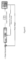
Figure 2 is a schematic diagram showing example inputs and outputs of the ECMS; -
Figure 3 is a schematic diagram showing an implementation of the arrangement of the disclosure; -
Figure 4 is a schematic diagram showing a more specific implementation of the arrangement ofFigure 3 ; -
Figure 5 is a schematic diagram of a specific implementation of the arrangement of the disclosure. - Referring to
Figure 1 , there is illustrated anengine assembly 1 comprising anengine 20, arecovery device 40, atransducer 60 and acontroller 100. - The
engine 20 is configured to receivefuel 15 from a fuel tank 5 and to convert energy in the fuel intoprimary output energy 25 andsecondary output energy 35. Theprimary output energy 25 may take the form of kinetic energy in a rotating crankshaft. The rotating crankshaft may be connected to anengine load 1000, perhaps via a gear box (which may or may not be considered to constitute a part of a load). - The
secondary output energy 35 may comprise secondary output kinetic energy and/or secondary output thermal energy. Thesecondary output energy 35 may be supplied to therecovery device 40. Therecovery device 40 may be configured to convert thesecondary output energy 35 topotential energy 45. Optionally, theengine assembly 1 comprises a potential energy storage feature 50. Where thepotential energy 45 is electrical potential energy, the potentialenergy storage feature 45 may be a battery 50. -
Potential energy 45, either supplied directly from therecovery device 40 or from the potential energy storage feature 50 may be supplied to thetransducer 60. Thetransducer 60 is suitable for converting thepotential energy 45 intotertiary energy 65 for conversion by theengine 20 into primary output energy 25 (and potentially also secondary output energy 35). - The
controller 100 is configured to implement an equivalent consumption minimisation strategy. This may be achieved using a data library which may be derived from offline engine modelling. Alternatively, equivalent consumption minimisation strategy may be achieved by online calculations in the engine controller. Thecontroller 100 controls supply offuel 15 from the fuel tank 5 to theengine 20 and supply oftertiary energy 65 from thetransducer 60 to theengine 20. In particular, it controls the ratio of energy to be derived in theengine 20 fromfuel 15 to energy to be derived in the engine fromtertiary energy 65. - The
controller 100 comprisescontrol lines fuel supply 15, therecovery device 40, where present a battery 50, thetransducer 60 and theengine 20, respectively. The control lines may exercise control directly or indirectly. In respect of thefuel supply 15 control, this may be achieved, for example, by controlling the demanded engine load on the crankshaft. - EMCS is achieved by applying a search algorithm wherein the algorithm attempts to find a minimum fuel consumption for a given set of conditions. In an online system the data resulting in minimum predicted fuel consumption would be calculated in real time. In an offline system, a model of the system would attempt to predict the best possible outcome and output it to the data library for online retrieval by the
controller 100. It may be that expected drive cycles can be used to identify optimised values for the desired condition. This is particularly relevant when using an offline model. - In simple terms, the input and output of the ECMS are shown in
Figure 2 . The input represents the demands while the corresponding output indicates a predicted most efficient solution of X kW of energy to be derived fromtertiary energy 65 and Y kW of energy to be derived fromfuel 15. - In a more specific embodiment of the invention, the
secondary output energy 35 may comprise secondary outputkinetic energy 35. Specifically, the secondary outputkinetic energy 35 may comprise kinetic energy of an exhaust gas produced in theengine 20. In this case, therecovery device 40 may comprise anelectric generator 40 for converting the secondary outputkinetic energy 35 of the gas intopotential energy 45 which is electricalpotential energy 45. Electricalpotential energy 45 may or may not be transmitted to a battery 50 for storage. In this embodiment, thetransducer 60 may comprise a motor. Themotor 60 may receivepotential energy 45 either directly from theelectric generator 40 or from the battery 50. In this embodiment, it may be that thegenerator 40 and theelectric motor 60 are a single electric machine. Furthermore, theelectric generator 40 and electric motor 60 (whether or not a single machine) may be part of a turbo charger. - The battery 50 may comprise additional sources of electrical potential energy and additional drains of electrical potential energy beyond those explicitly described. That is to say, the battery may comprise inputs other than that from the
recovery device 40 and outputs other than that from that to thetransducer 60. - In an alternative embodiment, the
recovery device 40 may comprise a thermo electric device for conversion of secondary outputthermal energy 35. This second embodiment may or may not include a battery 50 or other electrical potential energy storage device for storage or electrical potential energy derived in theelectric device 40. - Other alternative embodiments fall within the scope of the appended claims. In particular, any conceivable recovery of
secondary energy 35 by means of arecovery device 40 and redeployment of that energy using atransducer 60 to provideenergy 65 back to anengine 20 for more efficient use is contemplated. - The arrangement of the disclosure recognises the significance of engines generally having significantly lower efficiencies than transmission systems to which the engine may be coupled. At the heart of the disclosure is therefore an attempt not simply to recover secondary energy which would not otherwise usefully be used, but to seek to recover that secondary energy as close to the source of that secondary energy as possible. In the case of an engine, it might, for example be the case that 70% of the energy produced constitutes secondary energy. Therefore, even if a small proportion of the 70% secondary energy can be recovered for useful use either immediately or a later time, this represents a significant energy efficiency advantage. Therefore the application of ECMS to an engine assembly may yield better efficiency improvements than when applied to a transmission system comprising an engine assembly.
- Furthermore, the use of an equivalent consumption minimisation strategy allows for predicting how best to achieve a particular desired output in terms of availability of primary energy directly from the fuel and availability of primary energy derived from recovery of secondary energy via the arrangement of the disclosure. Furthermore, the strategy allows for predictions about likely future engine desired behaviour to reduce overall fuel consumption for the same benefit over an extended period.
- The ECMS control techniques of the arrangement of the disclosure may be used in combination with other known control techniques including, but not limited to, fuzzy logic and feedback linearization.
-
Control lines controller 100 to their respective engine assembly features. Instead, one or more of these control lines may go via one or more other lower level controllers for more specialised onward processing, the result of which being sent to the respective engine assembly features. Such lower level controllers include, but are not limited to an MPC or EMPC controller. - The detailed description of this disclosure has been made with respect to a small number of embodiments. The scope of the present disclosure is to be considered in light of the appended claims. It should not be inferred that one or more specific implementations of the desired description is intended to limit the scope of the claims beyond the scope of the claims themselves.
Claims (15)
- An engine assembly 1 comprising:an engine 20 configured to convert energy in a fuel 15 into primary output energy 25 and secondary output energy 35 wherein the primary output energy 25 consists solely of primary output kinetic energy in the form of a rotating crankshaft for onward transmission to a gearbox and/or a load 1000 and the secondary output energy 35 comprises secondary output kinetic energy and secondary output thermal energy;a recovery device 40 configured to convert the secondary output energy 35 to potential energy;a transducer 60 suitable for converting the potential energy 45 to tertiary energy 65 for conversion either directly or by the engine 20 into primary output energy 25; anda controller 100 configured to implement an equivalent consumption minimization strategy in order to control overall consumption of fuel by continuously optimising a proportion of the primary output energy 25 derived from the energy in the fuel 15 and a proportion of the primary output energy 25 derived from the tertiary energy 65.
- The engine assembly 1 of Claim 1, the engine assembly 1 further comprising a potential energy storage device 50 for storing the potential energy derived in the recovery device 40 for possible later use by the transducer 60.
- The engine assembly 1 of Claim 2, the engine assembly 1 further comprising an output for providing potential energy 45 from the potential energy storage device 50 to a device outside the engine assembly 1.
- The engine assembly 1 of any preceding claim wherein the secondary output kinetic energy 35 comprises kinetic energy of a gas, said kinetic energy of the gas being a product of conversion of the energy in a fuel 15 into primary output energy 25 and secondary output energy 35.
- The engine assembly 1 of any preceding claim wherein the potential energy 45 comprises electrical potential energy 45.
- The engine assembly 1 of any preceding claim wherein the recovery device 40 comprises an electric generator 40.
- The engine assembly 1 of any preceding claim wherein the transducer 60 comprises an electric motor 60.
- The engine assembly 1 of Claim 7 when dependent on Claim 6 wherein an electric machine comprises both the recovery device 40 and the transducer 60.
- The engine assembly 1 of any preceding claim wherein one or more turbo chargers comprise the recovery device 40 and/or the transducer 60.
- The engine assembly 1 of any preceding claim wherein the recovery device 40 comprises a thermoelectric device 40 for conversion of secondary output thermal energy 35.
- The engine assembly 1 of any preceding claim wherein the controller 100 outputs data to one or more further controllers for further processing to provide further processed data for controlling the engine assembly 1, wherein one or more of the further controllers may, optionally, implement EMPC control.
- A method for controlling an engine assembly 1, the engine assembly 1 comprising:an engine 20 configured to convert energy in a fuel 15 into primary output energy 25 and secondary output energy 35 wherein the primary output energy 25 consists solely of primary output kinetic energy in the form of a rotating crankshaft for onward transmission to a gearbox and/or a load 1000 and the secondary output energy 35 comprises secondary output kinetic energy and secondary output thermal energy;a recovery device 40 configured to convert the secondary output energy 35 to potential energy 45; anda transducer 60 suitable for converting the potential energy 45 to tertiary energy 65 for conversion by the engine 20 into primary output energy 25;the method comprising:implementing an equivalent consumption minimization strategy in order to control overall consumption of fuel by continuously optimising a proportion of the primary output energy 25 derived from the energy in the fuel 15 and a proportion of the primary output energy 25 derived from the tertiary energy 65.
- The method of Claim 12 wherein the step of implementing the equivalent consumption minimization strategy comprises either:using a model derived data library of the controller 100 to retrieve a value representative of a proportion of the primary output energy 25 to be derived from the energy in the fuel 15 and a proportion of the primary output energy 25 to be derived from the tertiary energy 65 in order to control overall consumption of fuel 15; orperforming a real time model based calculation of a value representative of a proportion of the primary output energy 25 to be derived from the energy in the fuel 15 and a proportion of the primary output energy 25 to be derived from the tertiary energy 65 in order to control overall consumption of fuel 15.
- The method of Claim 12 or Claim 13 wherein the method further comprises:obtaining either by online calculation or by retrieval from a data library a set of engine parameter values predicted to achieve a desired result using the engine 20 to convert energy in the fuel 15 into primary output energy 25; andobtaining either by online calculation or from the data library a set of engine parameter values predicted to achieve the same desired result using the transducer 60 to convert the potential energy 45 to tertiary energy 65 for conversion by the engine 20 into primary output energy 25.
- The method of any of Claims 12, 13 and 14, wherein the equivalent consumption minimization strategy provides values for control signals 101, 102, 103, 104, 105 which determine fuel efficient strategy for a specified future period based on likely future engine assembly behaviour requirements according to the model.
Priority Applications (4)
| Application Number | Priority Date | Filing Date | Title |
|---|---|---|---|
| EP12160010.0A EP2639437A1 (en) | 2012-03-16 | 2012-03-16 | Control system for an engine assembly |
| PCT/GB2013/050669 WO2013136092A1 (en) | 2012-03-16 | 2013-03-15 | Control system for an engine assembly |
| CN201380014521.6A CN104508285B (en) | 2012-03-16 | 2013-03-15 | Control system for engine pack |
| US14/385,716 US20150046067A1 (en) | 2012-03-16 | 2013-03-15 | Control System for an Engine Assembly |
Applications Claiming Priority (1)
| Application Number | Priority Date | Filing Date | Title |
|---|---|---|---|
| EP12160010.0A EP2639437A1 (en) | 2012-03-16 | 2012-03-16 | Control system for an engine assembly |
Publications (1)
| Publication Number | Publication Date |
|---|---|
| EP2639437A1 true EP2639437A1 (en) | 2013-09-18 |
Family
ID=47997578
Family Applications (1)
| Application Number | Title | Priority Date | Filing Date |
|---|---|---|---|
| EP12160010.0A Withdrawn EP2639437A1 (en) | 2012-03-16 | 2012-03-16 | Control system for an engine assembly |
Country Status (4)
| Country | Link |
|---|---|
| US (1) | US20150046067A1 (en) |
| EP (1) | EP2639437A1 (en) |
| CN (1) | CN104508285B (en) |
| WO (1) | WO2013136092A1 (en) |
Citations (4)
| Publication number | Priority date | Publication date | Assignee | Title |
|---|---|---|---|---|
| WO2005098225A1 (en) * | 2004-04-07 | 2005-10-20 | Toyota Jidosha Kabushiki Kaisha | Exhaust heat recovery power generation device and automobile equipped therewith |
| US20060000651A1 (en) * | 2004-06-30 | 2006-01-05 | Stabler Francis R | Thermoelectric augmented hybrid electric propulsion system |
| US20080098972A1 (en) * | 2006-10-30 | 2008-05-01 | Shane Elwart | Engine System Having Improved Efficiency |
| WO2011067622A1 (en) * | 2009-12-04 | 2011-06-09 | Renault Trucks | Vehicle combustion engine arrangement comprising a thermoelectric device |
Family Cites Families (6)
| Publication number | Priority date | Publication date | Assignee | Title |
|---|---|---|---|---|
| JPH10148120A (en) * | 1996-11-18 | 1998-06-02 | Isuzu Ceramics Kenkyusho:Kk | Heat recovery device for power supply engine |
| US6832634B1 (en) * | 2003-10-29 | 2004-12-21 | Vinit Chantalat | Method and apparatus for carbonating bottled liquid with minimum oxygen entrainment |
| EP2052926A1 (en) * | 2006-08-18 | 2009-04-29 | Kabushiki Kaisha Atsumitec | Drive device for vehicle |
| JP5448873B2 (en) * | 2010-01-21 | 2014-03-19 | 三菱重工業株式会社 | ENGINE EXHAUST ENERGY RECOVERY DEVICE, SHIP HAVING THE SAME, POWER GENERATION PLANT HAVING THE SAME, ENGINE EXHAUST ENERGY RECOVERY DEVICE CONTROL DEVICE AND ENGINE EXHAUST ENERGY RECOVERY DEVICE CONTROL METHOD |
| CN102182583B (en) * | 2011-04-13 | 2013-11-06 | 北京理工大学 | Combined-type residual heat recovery system suitable for internal combustion engine |
| CN102434257B (en) * | 2011-11-17 | 2013-08-14 | 徐明奇 | Power generation device using waste heat of engines of vehicles and ships |
-
2012
- 2012-03-16 EP EP12160010.0A patent/EP2639437A1/en not_active Withdrawn
-
2013
- 2013-03-15 CN CN201380014521.6A patent/CN104508285B/en not_active Expired - Fee Related
- 2013-03-15 WO PCT/GB2013/050669 patent/WO2013136092A1/en not_active Ceased
- 2013-03-15 US US14/385,716 patent/US20150046067A1/en not_active Abandoned
Patent Citations (4)
| Publication number | Priority date | Publication date | Assignee | Title |
|---|---|---|---|---|
| WO2005098225A1 (en) * | 2004-04-07 | 2005-10-20 | Toyota Jidosha Kabushiki Kaisha | Exhaust heat recovery power generation device and automobile equipped therewith |
| US20060000651A1 (en) * | 2004-06-30 | 2006-01-05 | Stabler Francis R | Thermoelectric augmented hybrid electric propulsion system |
| US20080098972A1 (en) * | 2006-10-30 | 2008-05-01 | Shane Elwart | Engine System Having Improved Efficiency |
| WO2011067622A1 (en) * | 2009-12-04 | 2011-06-09 | Renault Trucks | Vehicle combustion engine arrangement comprising a thermoelectric device |
Also Published As
| Publication number | Publication date |
|---|---|
| US20150046067A1 (en) | 2015-02-12 |
| CN104508285A (en) | 2015-04-08 |
| CN104508285B (en) | 2018-02-27 |
| WO2013136092A1 (en) | 2013-09-19 |
Similar Documents
| Publication | Publication Date | Title |
|---|---|---|
| Memon et al. | Selective harmonic elimination in inverters using bio-inspired intelligent algorithms for renewable energy conversion applications: A review | |
| Ripaccioli et al. | A stochastic model predictive control approach for series hybrid electric vehicle power management | |
| Mazumdar et al. | GAO optimized sliding mode based reconfigurable step size Pb&O MPPT controller with grid integrated EV charging station | |
| Gökce et al. | An instantaneous optimization strategy based on efficiency maps for internal combustion engine/battery hybrid vehicles | |
| Boukoberine et al. | Optimized energy management strategy for hybrid fuel cell powered drones in persistent missions using real flight test data | |
| KR101766260B1 (en) | Method for Ship Energy Efficiency Optimization | |
| EP3018787A1 (en) | Microgrid control device and control method therefor | |
| US20160036450A1 (en) | Method of optimizing dispatch of variable speed engine-generator sets | |
| Malikopoulos | Stochastic optimal control for series hybrid electric vehicles | |
| Safari et al. | Optimal load sharing strategy for a wind/diesel/battery hybrid power system based on imperialist competitive neural network algorithm | |
| Kishore et al. | A new meta-heuristic optimization-based MPPT control technique for green energy harvesting from photovoltaic systems under different atmospheric conditions | |
| Nino-Baron et al. | Trajectory optimization for the engine–generator operation of a series hybrid electric vehicle | |
| Korada et al. | Energy management strategy for photovoltaic powered hybrid energy storage systems in electric vehicles. | |
| Junior et al. | A LQR design with rejection of disturbances and robustness to load variations applied to a buck converter | |
| Sarkar et al. | Hybrid Energy Storage Systems, Converter Topologies, Energy Management Systems, and Future Prospects of Green Marine Technology: A Comprehensive Review | |
| Abdelqawee et al. | Implementation of a novel hybrid optimizer for energy management of fuel cell/battery/supercapacitor system | |
| EP2639437A1 (en) | Control system for an engine assembly | |
| Sowmya et al. | Frequency Regulation in multi-microgrid power system using an adaptive beluga whale optimizer-based FOPID controller | |
| JP2014082932A (en) | Electric power system planning apparatus and electric power system planning method | |
| Deffo et al. | Comparative study of optimal frequency control in a microgrid via a PID and (1+ PD)-PID controllers | |
| Mitropoulou et al. | Multi-objective optimisation and Energy Management: adapt your ship to every mission | |
| Fayaz et al. | Optimal control of hybrid power system integrated with distributed generation and electric vehicle | |
| Nath et al. | Comparative analysis of the MFO tuned PID controller based autonomous power system | |
| Goddu et al. | Enhancing electric vehicle performance and sustainability through advanced energy management systems | |
| Pandurangam et al. | An innovative Dandelion Optimized Network Control (DONC) based effective energy management system for electric ships |
Legal Events
| Date | Code | Title | Description |
|---|---|---|---|
| PUAI | Public reference made under article 153(3) epc to a published international application that has entered the european phase |
Free format text: ORIGINAL CODE: 0009012 |
|
| AK | Designated contracting states |
Kind code of ref document: A1 Designated state(s): AL AT BE BG CH CY CZ DE DK EE ES FI FR GB GR HR HU IE IS IT LI LT LU LV MC MK MT NL NO PL PT RO RS SE SI SK SM TR |
|
| AX | Request for extension of the european patent |
Extension state: BA ME |
|
| RIN1 | Information on inventor provided before grant (corrected) |
Inventor name: LANGLEY, THOMAS Inventor name: THAO, DEZONG Inventor name: DENG, JIAMEI Inventor name: STOBART, RICHARD |
|
| 17P | Request for examination filed |
Effective date: 20140318 |
|
| RBV | Designated contracting states (corrected) |
Designated state(s): AL AT BE BG CH CY CZ DE DK EE ES FI FR GB GR HR HU IE IS IT LI LT LU LV MC MK MT NL NO PL PT RO RS SE SI SK SM TR |
|
| STAA | Information on the status of an ep patent application or granted ep patent |
Free format text: STATUS: EXAMINATION IS IN PROGRESS |
|
| 17Q | First examination report despatched |
Effective date: 20200506 |
|
| STAA | Information on the status of an ep patent application or granted ep patent |
Free format text: STATUS: THE APPLICATION IS DEEMED TO BE WITHDRAWN |
|
| 18D | Application deemed to be withdrawn |
Effective date: 20230420 |