EP2639311A1 - Genetic testing method and testing apparatus - Google Patents
Genetic testing method and testing apparatus Download PDFInfo
- Publication number
- EP2639311A1 EP2639311A1 EP11840150.4A EP11840150A EP2639311A1 EP 2639311 A1 EP2639311 A1 EP 2639311A1 EP 11840150 A EP11840150 A EP 11840150A EP 2639311 A1 EP2639311 A1 EP 2639311A1
- Authority
- EP
- European Patent Office
- Prior art keywords
- temperature
- value
- reaction tube
- reaction
- corrected
- Prior art date
- Legal status (The legal status is an assumption and is not a legal conclusion. Google has not performed a legal analysis and makes no representation as to the accuracy of the status listed.)
- Granted
Links
Images


Classifications
-
- B—PERFORMING OPERATIONS; TRANSPORTING
- B01—PHYSICAL OR CHEMICAL PROCESSES OR APPARATUS IN GENERAL
- B01L—CHEMICAL OR PHYSICAL LABORATORY APPARATUS FOR GENERAL USE
- B01L7/00—Heating or cooling apparatus; Heat insulating devices
- B01L7/52—Heating or cooling apparatus; Heat insulating devices with provision for submitting samples to a predetermined sequence of different temperatures, e.g. for treating nucleic acid samples
-
- G—PHYSICS
- G01—MEASURING; TESTING
- G01N—INVESTIGATING OR ANALYSING MATERIALS BY DETERMINING THEIR CHEMICAL OR PHYSICAL PROPERTIES
- G01N35/00—Automatic analysis not limited to methods or materials provided for in any single one of groups G01N1/00 - G01N33/00; Handling materials therefor
- G01N35/00584—Control arrangements for automatic analysers
- G01N35/00594—Quality control, including calibration or testing of components of the analyser
- G01N35/00613—Quality control
- G01N35/00623—Quality control of instruments
-
- C—CHEMISTRY; METALLURGY
- C12—BIOCHEMISTRY; BEER; SPIRITS; WINE; VINEGAR; MICROBIOLOGY; ENZYMOLOGY; MUTATION OR GENETIC ENGINEERING
- C12Q—MEASURING OR TESTING PROCESSES INVOLVING ENZYMES, NUCLEIC ACIDS OR MICROORGANISMS; COMPOSITIONS OR TEST PAPERS THEREFOR; PROCESSES OF PREPARING SUCH COMPOSITIONS; CONDITION-RESPONSIVE CONTROL IN MICROBIOLOGICAL OR ENZYMOLOGICAL PROCESSES
- C12Q1/00—Measuring or testing processes involving enzymes, nucleic acids or microorganisms; Compositions therefor; Processes of preparing such compositions
- C12Q1/68—Measuring or testing processes involving enzymes, nucleic acids or microorganisms; Compositions therefor; Processes of preparing such compositions involving nucleic acids
- C12Q1/6844—Nucleic acid amplification reactions
- C12Q1/686—Polymerase chain reaction [PCR]
-
- G—PHYSICS
- G01—MEASURING; TESTING
- G01N—INVESTIGATING OR ANALYSING MATERIALS BY DETERMINING THEIR CHEMICAL OR PHYSICAL PROPERTIES
- G01N35/00—Automatic analysis not limited to methods or materials provided for in any single one of groups G01N1/00 - G01N33/00; Handling materials therefor
- G01N2035/00346—Heating or cooling arrangements
-
- G—PHYSICS
- G01—MEASURING; TESTING
- G01N—INVESTIGATING OR ANALYSING MATERIALS BY DETERMINING THEIR CHEMICAL OR PHYSICAL PROPERTIES
- G01N35/00—Automatic analysis not limited to methods or materials provided for in any single one of groups G01N1/00 - G01N33/00; Handling materials therefor
- G01N2035/00346—Heating or cooling arrangements
- G01N2035/00356—Holding samples at elevated temperature (incubation)
- G01N2035/00366—Several different temperatures used
-
- G—PHYSICS
- G01—MEASURING; TESTING
- G01N—INVESTIGATING OR ANALYSING MATERIALS BY DETERMINING THEIR CHEMICAL OR PHYSICAL PROPERTIES
- G01N35/00—Automatic analysis not limited to methods or materials provided for in any single one of groups G01N1/00 - G01N33/00; Handling materials therefor
- G01N35/00584—Control arrangements for automatic analysers
- G01N35/00722—Communications; Identification
- G01N2035/00891—Displaying information to the operator
- G01N2035/009—Displaying information to the operator alarms, e.g. audible
Definitions
- the present invention relates to an analysis method and an apparatus for the same that qualitatively or quantitatively analyze a target nucleic acid included in a biological sample such as blood or urine, and the method and the apparatus are targeted for techniques that need temperature changes in course of amplification and detection in a reaction solution and techniques that do not need temperature changes in course of amplification and detection in a reaction solution.
- nucleic acid amplification techniques such as polymerase chain reaction (in the following, PCR), which is a technique that needs temperature changes in course of amplification and detection in a reaction solution, and a loop-mediated isothermal amplification method (in the following, a LAMP method), which is a technique that does not need temperature changes in course of amplification and detection in a reaction solution.
- PCR polymerase chain reaction
- LAMP method loop-mediated isothermal amplification method
- a sample is heated at a temperature of 94°C to separate a double strand into single strands, annealed at a temperature of 60°C, and kept at a temperature of 60 to 72°C for a few minutes.
- the PCR process is repeated for n times to amplify a target nucleic acid of an object.
- the LAMP method reactions proceed at a constant temperature, at a temperature of 60 to 65°C.
- amplification is performed at a certain constant temperature range as described above. Since it is important to accurately control the temperatures of a plurality of reaction tubes at a predetermined temperature, the present invention is also applicable to the LAMP method. Moreover, the amplification temperature is sometimes different depending on samples.
- Patent Literature 1 In order to implement this periodical temperature control method in PCR, in Patent Literature 1 described below, an apparatus is disclosed in which the apparatus includes regions, in which the temperature is kept at different set temperatures, and a disc-like sample holder and the temperature of a sample is periodically changed by rotating a disc.
- a temperature controller is individually provided on temperature adjusting blocks in which a reaction tube is held in order to enable simultaneous processing of a plurality of types of reaction solutions in different protocols and enable starting processing of a different reaction solution even during analysis.
- a genetic testing method and a testing apparatus in which a genetic testing apparatus includes: a heating and cooling unit that houses a plurality of reaction tubes and controls temperature at individual positions to hold the reaction tubes, the reaction tubes each accommodating a target nucleic acid to be amplified and a component necessary for amplification; a temperature monitoring unit that monitors a controlled temperature value of the reaction tube; and a light emission detecting unit that measures light emission of a reaction solution accommodated in the reaction tube.
- the genetic testing apparatus includes a function in which a controlled temperature value is monitored in a unit of the reaction tube and a controlled temperature value is corrected in a unit of the reaction tube.
- the temperature controller is individually provided on the reaction tubes in order to enable simultaneous processing of a plurality of types of reaction solutions in different protocols and enable starting processing of a different reaction solution even during analysis.
- the provision of the temperature controllers causes dimension errors between the temperature adjusting blocks in which the tube is held and individual differences between electric heating devices and between temperature detecting devices, and the block and the devices configure the temperature controller. Factors possibly caused in industrial products such as deterioration over time in the devices cause individual differences between the temperature controllers. For the dimension errors, the individual differences between the devices, and the individual differences between the temperature controllers, a difference between a target temperature and an actual temperature caused in the individual reaction tubes controlled by a plurality of the temperature control mechanisms can be controlled within a certain range.
- the present invention relates to a genetic testing apparatus including: a plurality of reaction tubes each provided with a temperature variable temperature control mechanism for nucleic acid amplification by PCR reaction; a unit that heats and cools the reaction tube and a unit that detects the temperature of the reaction tube, the units individually provided on holder portions for the reaction tubes; a storage unit that stores a corrected temperature value, a monitored temperature, and measured data; a unit that compares stored data with a measured value of the reaction tube and computes a corrected temperature value; a unit that corrects the temperature of the reaction tube based on the corrected value; and a detector that applies pumping light to a reaction solution in the reaction tube after amplification and detects light emission such as fluorescence.
- the temperature of the temperature control mechanism for each reaction tube is corrected, so that temperature can be highly accurately controlled.
- the transition of stored corrected temperature values is monitored, so that it is also useful to monitor an abnormal state or useful for the purpose of prevention and integrity.
- a highly reliable apparatus can be provided in which a monitored controlled temperature value during execution of a nucleic acid detection protocol or measured data of detected fluorescence is displayed on the manipulation screen of the apparatus and an apparatus operator can easily recognize the presence or absence of an abnormality of temperature control in measured data.
- the present invention is to provide a highly reliable apparatus that can reduce individual differences between a plurality of temperature adjusting devices due to factors possibly caused in industrial products because a temperature controller is individually provided on the reaction tubes and can easily recognize an abnormal operation in the apparatus.
- the apparatus includes a unit that stores a corrected controlled temperature value, temperature control data, and measured fluorescence data of a plurality of tube holder portions, and monitors and displays stored values using an arithmetic device that controls the overall apparatus.
- a plurality of protocols with different temperature cycles can be analyzed simultaneously. Even though analysis already proceeds in the apparatus, a new sample can be analyzed. It can be said that this is a practical feature in the case where the present invention is applied not only to PCR but also to a LAMP method.
- a genetic testing method and a testing apparatus are provided in which a measured result can be easily traced by displaying temperature control data during execution of an analysis protocol and an analyzed result profile on a screen.
- the present invention is performed, so that it is possible to highly accurately control temperature while maintaining equivalent performances between the positions to hold the reaction tubes even though a temperature cycle is performed by any temperature control mechanism of a plurality of the temperature control mechanisms.
- a reaction tube accommodates a buffer solution, for example, to provide an optimum temperature environment in which a target nucleic acid to be amplified, primers, a target nucleic acid polymerase, deoxynucleotide triphosphate (dNTP) that is a material (a substrate) for target nucleic acid rigidity, and an enzyme work.
- a reaction tube accommodates necessary components for amplification. Since the LAMP method itself is a well-known method, the detailed description is omitted.
- a genetic testing method includes: independently controlling temperatures of a plurality of reaction tubes using a thermostat, a temperature detecting device, and a heating and cooling device additionally provided on each of the reaction tubes, the reaction tubes each accommodating a target nucleic acid to be amplified and a component necessary for amplification; controlling temperature at individual positions to hold the reaction tubes and at a predetermined temperature set at the individual positions according to an analysis and testing protocol predetermined at individual positions of the reaction tubes; outputting a controlled temperature value of the reaction tube to a monitor; monitoring a controlled temperature value in a unit of the reaction tube and computing a corrected value of a controlled temperature value in a unit of the reaction tube; controlling temperatures of the reaction tubes; and measuring light emission of amplification accommodated in the reaction tube.
- the temperatures of a plurality of the reaction tubes can be individually controlled and monitored, so that correction can be independently performed in a unit of the reaction tube, and a difference between the actual temperature of the reaction tube and the target temperature can be made smaller.
- correction can be performed on each temperature adjusting device, so that individual differences between a plurality of temperature controllers can be reduced.
- the controlled temperature value is a controlled temperature range of a reaction tube determined by a genetic testing protocol, and is a predetermined temperature range including allowable errors.
- the corrected temperature value is a corrected value changed due to the specification of the apparatus, components, an environment in which tests are carried out, or the like, and a corrected value is found any time by a measured value and computation.
- the temperature control unit is a unit that performs general temperature control according to the protocol. When it is determined that the temperature control unit does not correctly perform control, the controlled temperature value is corrected based on necessary data stored on the storage device.
- Fig. 1 is a schematic diagram of the overall structure of a nucleic acid analyzer to which the present invention was implemented.
- a nucleic acid analyzer 1 is connected to a monitor 30, a storage device 40, and an arithmetic device 50 through a communication cable 60, and the monitor is operated as a manipulating unit to control the nucleic acid analyzer 1.
- the storage device 40 includes a corrected temperature value storage unit 41, a monitored temperature storage unit 42, and a measured data storage unit 43.
- Fig. 2 is a block diagram of the inside of the nucleic acid analyzer 1. Main mechanisms and components in Fig. 2 will be described.
- a dispensing unit 2 sucks and discharges a liquid.
- a gripper unit 3 holds a reaction tube 4 one by one.
- the dispensing unit 2 and the gripper unit 3 are connected to a robot arm X-shaft 5 and a robot arm Y-shaft 6, and moved on a plane, and can move a reaction tube in the grip of the gripper unit 3 according to a predetermined procedure.
- a dispenser chip 9 is stocked on a nozzle chip rack 10.
- the dispenser chip 9 is a single-use (disposable) chip in order to prevent contamination.
- the reaction tube 4 is a container to which a sample and a reagent are discharged, and stocked on a reaction tube rack 11.
- a nucleic acid amplification unit 12 is configured of a plurality of thermostats 16, a robot arm 17 disposed above the thermostats, and a plurality of detectors disposed around the thermostats 16, and a temperature detecting device 15 shown in Fig. 4 , for example.
- a plurality of the reaction tubes 4 can be disposed on the plurality of thermostats 16, and the reaction tubes and the thermostats are disposed in a one-to-one relationship.
- temperature control in which the reaction tubes 4 can be individually controlled and monitored.
- the typical operating steps of the automatic analyzer of the nucleic acid analyzer 1 are performed by transporting the reaction tube 4 to a reaction solution adjusting position 18 using the gripper unit 3.
- the dispenser chips 9 are mounted on the dispensing unit 2, and a sample and a reagent are individually sucked from a sample and reagent container 19 including the sample, and discharged into the reaction tubes 4 at the reaction solution adjusting position 18. The reagent is also discharged into the reaction tubes 4 by similar procedures.
- the used dispenser chips 9 are disposed of in a disposal box 20 in order to prevent contamination.
- the reaction tubes 4 to which the sample and the reagent are discharged are closed with lids and hermetically sealed at a closing unit 21, stirred at a stirring unit 22, and loaded into the nucleic acid amplification unit 12 for detection at a detector 13.
- the reaction tubes 4 after finishing the detecting step are dispose of in the disposal box 20 using the gripper unit 3.
- the reaction tubes 4 are loaded into and unloaded from the nucleic acid amplification unit 12 by opening and closing a gate 23.
- the temperatures of the individual thermostats are heated or cooled using an electric heating device, and the temperatures are constantly monitored using a pole temperature detecting device for control so as to perform a predetermined temperature profile, so that control and management can be performed in a unit of the reaction tube even in the case where it is necessary to manage a plurality of temperatures like PCR. Therefore, the quantification step of nucleic acids by nucleic acid amplification can be easily automated.
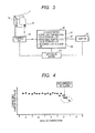
- Fig. 3 is a schematic diagram of the configuration of a temperature control system according to the example of the present invention. Although a plurality of the reaction tubes 4 can be disposed on the thermostats 16, Fig. 3 is a conceptual diagram extracting a block diagram of a single reaction tube 4 and a control system belonging to the reaction tube 4. The controlled temperature value of a liquid accommodated in the reaction tube 4 is instructed from the computer 50, and the control system controls the temperature to increase or decrease for reaching a target temperature using an electric heating device 14. The actual temperature is then monitored using the temperature detecting device 15, and controlled to reach a target temperature.
- such a configuration is provided in which temperature can be independently corrected for all of a plurality of the temperature control systems disposed on the reaction tubes 4, that is, disposed on the thermostats 16 on solid difference factors in the temperature control systems. Furthermore, the corrected temperature values, the monitored temperature values, and measured data detected at the detector 13 are stored as electronic data on the storage device 40, and can also be read for display on the monitor by an instruction from the computer. In addition, such a configuration is provided in which for these items of data, temperature control states can be monitored by monitoring statistical transition or the like and the alarm can be given in the case where an abnormal state is recognized.
- Fig. 4 is an example when the transitions of corrected temperature values are monitored.
- an operator or a service person of the apparatus can correct the temperature of temperature control configurations and can read stored corrected temperature values at a given timing.
- the corrected temperature values are varied for each correction, it can be determined that the temperature control systems are in normal states when variations converge on a specific variation range.
- the apparatus recognizes an abnormal state and gives the alarm.
- Fig. 5A is a specific example of the temporal transition of increases and decreases in target temperatures in an analysis protocol, showing a target temperature profile that the temperature profile also includes temporal control factors.
- Fig. 5B is a specific example of the temporal transition of monitored temperature values and measured fluorescent data stored on the arithmetic device.
- the temperature control system monitors the temperature of a reaction tube to be controlled on the temperature profile, also detects a fluorescent quantity as measured data simultaneously, and stores the temperature and the measured data.
- Fig. 5B Ones shown in Fig. 5B are the monitored temperature values and the measured data described above. In the PCR method, it is known that the accuracy of the temperature of the reaction tube is a large factor to possibly cause variations in measured data.
- a monitored temperature value and measured data are displayed simultaneously on the screen of the apparatus.
- a monitored temperature value and measured data can be confirmed simultaneously, so that also in the case where temperature is controlled abnormally in a specific control cycle to affect the accuracy of measured data as denoted as under abnormal temperature control, in the present invention, the abnormal state can be easily recognized, and a function to give the alarm can be easily implemented in the case where a monitoring range is exceeded by specifying a specific monitoring range.
- the present invention is implemented, so that a genetic testing apparatus of high operability and high reliability can be provided, in which temperature can be controlled and monitored in a unit of a reaction tube, the alarm can be given in a unit of a reaction tube, and an abnormal state can be recognized also on the screen of the apparatus.
- the present invention is effective as a temperature control technique for amplification and detection of genes using a PCR method or a LAMP method.
Landscapes
- Quality & Reliability (AREA)
- Engineering & Computer Science (AREA)
- Chemical & Material Sciences (AREA)
- Health & Medical Sciences (AREA)
- General Health & Medical Sciences (AREA)
- Biochemistry (AREA)
- Life Sciences & Earth Sciences (AREA)
- Pathology (AREA)
- Physics & Mathematics (AREA)
- General Physics & Mathematics (AREA)
- Immunology (AREA)
- Analytical Chemistry (AREA)
- Molecular Biology (AREA)
- Clinical Laboratory Science (AREA)
- Chemical Kinetics & Catalysis (AREA)
- Apparatus Associated With Microorganisms And Enzymes (AREA)
- Measuring Or Testing Involving Enzymes Or Micro-Organisms (AREA)
- Automatic Analysis And Handling Materials Therefor (AREA)
Abstract
Description
- The present invention relates to an analysis method and an apparatus for the same that qualitatively or quantitatively analyze a target nucleic acid included in a biological sample such as blood or urine, and the method and the apparatus are targeted for techniques that need temperature changes in course of amplification and detection in a reaction solution and techniques that do not need temperature changes in course of amplification and detection in a reaction solution.
- Conventionally, for the amplification and quantification of nucleic acids included in a sample derived from a living body, nucleic acid amplification techniques such as polymerase chain reaction (in the following, PCR), which is a technique that needs temperature changes in course of amplification and detection in a reaction solution, and a loop-mediated isothermal amplification method (in the following, a LAMP method), which is a technique that does not need temperature changes in course of amplification and detection in a reaction solution. In PCR, it is necessary to periodically change sample temperatures generally in two or three types of temperature ranges for nucleic acid amplification. For example, in a typical PCR method, a sample is heated at a temperature of 94°C to separate a double strand into single strands, annealed at a temperature of 60°C, and kept at a temperature of 60 to 72°C for a few minutes. The PCR process is repeated for n times to amplify a target nucleic acid of an object. On the other hand, in the LAMP method, reactions proceed at a constant temperature, at a temperature of 60 to 65°C. In the LAMP method, amplification is performed at a certain constant temperature range as described above. Since it is important to accurately control the temperatures of a plurality of reaction tubes at a predetermined temperature, the present invention is also applicable to the LAMP method. Moreover, the amplification temperature is sometimes different depending on samples.
- In order to implement this periodical temperature control method in PCR, in Patent Literature 1 described below, an apparatus is disclosed in which the apparatus includes regions, in which the temperature is kept at different set temperatures, and a disc-like sample holder and the temperature of a sample is periodically changed by rotating a disc.
- However, in PCR, temperature and time necessary for an annealing reaction to bind primers having a complementary sequence to a base sequence to be detected are different depending on sequences. Moreover, temperature and time necessary in an extension reaction are different depending on enzymes to be added. Thus, in order to simultaneously process base sequences to be detected, that is, a plurality of reaction solutions in different protocols, it is necessary to provide a nucleic acid amplifier, in which temperature and time defined by a protocol is set, by the number of protocols to be simultaneously processed.
- Furthermore, such a technique is known in which a plate is included to hold a plurality of samples and the temperature of the entire region of the plate is uniformly controlled. However, in PCR, a single temperature cycle is formed of a denaturation reaction, annealing reaction, and extension reaction, a certain number of cycles is repeated, and then analysis is ended. In the technique in which the entire region of the plate is uniformly controlled at a constant temperature, a new sample cannot be started for analysis after starting analysis of a sample, even though the new sample is in the same protocol, and it is necessary to wait for the end of analysis. Thus, the technique has a problem in that analysis time until the analyzed result of a new sample is obtained is prolonged.
-
- Patent Literature 1: Japanese Patent Application Laid-Open Publication No.
2008-185389 - Patent Literature 2: Japanese Patent Application Laid-Open Publication No.
H09-224644 - Patent Literature 3: Japanese Patent Application Laid-Open Publication No.
2006-115742 - It is an object of the present invention to provide a highly reliable method and apparatus for detecting genes, in which a temperature controller is individually provided on temperature adjusting blocks in which a reaction tube is held in order to enable simultaneous processing of a plurality of types of reaction solutions in different protocols and enable starting processing of a different reaction solution even during analysis. In the method and the apparatus, in the provision of the temperature controllers, individual differences between a plurality of the temperature controllers due to factors possibly caused in industrial products are eliminated, and an abnormal operation of the temperature control mechanism of the reaction tube for amplification of a target nucleic acid can be easily recognized.
- According to an aspect of the present invention, a genetic testing method and a testing apparatus can be provided, in which a genetic testing apparatus includes: a heating and cooling unit that houses a plurality of reaction tubes and controls temperature at individual positions to hold the reaction tubes, the reaction tubes each accommodating a target nucleic acid to be amplified and a component necessary for amplification; a temperature monitoring unit that monitors a controlled temperature value of the reaction tube; and a light emission detecting unit that measures light emission of a reaction solution accommodated in the reaction tube. The genetic testing apparatus includes a function in which a controlled temperature value is monitored in a unit of the reaction tube and a controlled temperature value is corrected in a unit of the reaction tube.
- According to an aspect of the present invention, the temperature controller is individually provided on the reaction tubes in order to enable simultaneous processing of a plurality of types of reaction solutions in different protocols and enable starting processing of a different reaction solution even during analysis. The provision of the temperature controllers causes dimension errors between the temperature adjusting blocks in which the tube is held and individual differences between electric heating devices and between temperature detecting devices, and the block and the devices configure the temperature controller. Factors possibly caused in industrial products such as deterioration over time in the devices cause individual differences between the temperature controllers. For the dimension errors, the individual differences between the devices, and the individual differences between the temperature controllers, a difference between a target temperature and an actual temperature caused in the individual reaction tubes controlled by a plurality of the temperature control mechanisms can be controlled within a certain range. Thus, even though a temperature cycle is performed by any temperature control mechanism of a plurality of the temperature control mechanisms, it is possible to highly accurately control temperature while maintaining equivalent performances between the positions to hold the reaction tubes. Moreover, it is possible to provide a highly reliable apparatus that can easily recognize an abnormal operation in the apparatus.
-
- [
Fig. 1] Fig. 1 is a schematic diagram of the overall structure of a genetic testing apparatus according to an example of the present invention. - [
Fig. 2] Fig. 2 is a schematic diagram of the internal configuration of the genetic testing apparatus according to an example of the present invention. - [
Fig. 3] Fig. 3 is a schematic diagram of the configuration of a temperature control system according to an example of the present invention. - [
Fig. 4] Fig. 4 is a graph of a specific example of transitions and monitoring of corrected temperature values according to an example of the present invention. - [
Fig. 5A] Fig. 5A is a specific example of transitions and monitoring of a temperature profile, temperature control data, and measured fluorescence data according to an example of the present invention. - [
Fig. 5B] Fig. 5B is a specific example of monitoring of a temperature profile, temperature control data, and measured fluorescence data according to an example of the present invention. - The present invention relates to a genetic testing apparatus including: a plurality of reaction tubes each provided with a temperature variable temperature control mechanism for nucleic acid amplification by PCR reaction; a unit that heats and cools the reaction tube and a unit that detects the temperature of the reaction tube, the units individually provided on holder portions for the reaction tubes; a storage unit that stores a corrected temperature value, a monitored temperature, and measured data; a unit that compares stored data with a measured value of the reaction tube and computes a corrected temperature value; a unit that corrects the temperature of the reaction tube based on the corrected value; and a detector that applies pumping light to a reaction solution in the reaction tube after amplification and detects light emission such as fluorescence.
- The temperature of the temperature control mechanism for each reaction tube is corrected, so that temperature can be highly accurately controlled. The transition of stored corrected temperature values is monitored, so that it is also useful to monitor an abnormal state or useful for the purpose of prevention and integrity. Moreover, a highly reliable apparatus can be provided in which a monitored controlled temperature value during execution of a nucleic acid detection protocol or measured data of detected fluorescence is displayed on the manipulation screen of the apparatus and an apparatus operator can easily recognize the presence or absence of an abnormality of temperature control in measured data.
- The present invention is to provide a highly reliable apparatus that can reduce individual differences between a plurality of temperature adjusting devices due to factors possibly caused in industrial products because a temperature controller is individually provided on the reaction tubes and can easily recognize an abnormal operation in the apparatus. The apparatus includes a unit that stores a corrected controlled temperature value, temperature control data, and measured fluorescence data of a plurality of tube holder portions, and monitors and displays stored values using an arithmetic device that controls the overall apparatus.
- Moreover, in the present invention, a plurality of protocols with different temperature cycles can be analyzed simultaneously. Even though analysis already proceeds in the apparatus, a new sample can be analyzed. It can be said that this is a practical feature in the case where the present invention is applied not only to PCR but also to a LAMP method. In the present invention, a genetic testing method and a testing apparatus are provided in which a measured result can be easily traced by displaying temperature control data during execution of an analysis protocol and an analyzed result profile on a screen.
- Furthermore, the present invention is performed, so that it is possible to highly accurately control temperature while maintaining equivalent performances between the positions to hold the reaction tubes even though a temperature cycle is performed by any temperature control mechanism of a plurality of the temperature control mechanisms.
In addition, it is possible to provide a highly reliable apparatus that can easily recognize or predict an abnormal operation in the apparatus. - In the present invention, in the case where a PCR method is used to detect genes, a reaction tube accommodates a buffer solution, for example, to provide an optimum temperature environment in which a target nucleic acid to be amplified, primers, a target nucleic acid polymerase, deoxynucleotide triphosphate (dNTP) that is a material (a substrate) for target nucleic acid rigidity, and an enzyme work. Also in a LAMP method, a reaction tube accommodates necessary components for amplification. Since the LAMP method itself is a well-known method, the detailed description is omitted.
- In the following, an embodiment of the present invention will be described. (1) A genetic testing method includes: independently controlling temperatures of a plurality of reaction tubes using a thermostat, a temperature detecting device, and a heating and cooling device additionally provided on each of the reaction tubes, the reaction tubes each accommodating a target nucleic acid to be amplified and a component necessary for amplification; controlling temperature at individual positions to hold the reaction tubes and at a predetermined temperature set at the individual positions according to an analysis and testing protocol predetermined at individual positions of the reaction tubes; outputting a controlled temperature value of the reaction tube to a monitor; monitoring a controlled temperature value in a unit of the reaction tube and computing a corrected value of a controlled temperature value in a unit of the reaction tube; controlling temperatures of the reaction tubes; and measuring light emission of amplification accommodated in the reaction tube.
- In a preferred embodiment of the present invention, it is necessary to independently control temperature at individual positions to hold the reaction tubes and at a predetermined temperature set at the individual positions according to an analysis and testing protocol predetermined at individual positions of the reaction tubes. Thus, the temperatures of a plurality of the reaction tubes can be individually controlled and monitored, so that correction can be independently performed in a unit of the reaction tube, and a difference between the actual temperature of the reaction tube and the target temperature can be made smaller. Moreover, correction can be performed on each temperature adjusting device, so that individual differences between a plurality of temperature controllers can be reduced.
- In the present invention, the controlled temperature value is a controlled temperature range of a reaction tube determined by a genetic testing protocol, and is a predetermined temperature range including allowable errors. Moreover, the corrected temperature value is a corrected value changed due to the specification of the apparatus, components, an environment in which tests are carried out, or the like, and a corrected value is found any time by a measured value and computation. These items of data are stored on a monitored temperature
value storage unit 42 and a corrected temperaturevalue storage unit 41. - Furthermore, the temperature control unit is a unit that performs general temperature control according to the protocol. When it is determined that the temperature control unit does not correctly perform control, the controlled temperature value is corrected based on necessary data stored on the storage device.
- (2) In the above-mentioned genetic testing method, an amplification reaction is performed by a PCR method.
- (3) In the above-mentioned genetic testing method, an amplification reaction is performed by a LAMP method.
- (4) In the above-mentioned genetic testing method, when a controlled temperature value of a specific reaction tube exceeds a normal range of stored corrected temperature values in course of a testing and detecting step, controlling a temperature of the reaction tube is stopped and remaining reaction tubes that converge on the normal range are used to continue analysis or testing. Here, analysis is preparation or pre-processing for genetic testing, and an analyzing step includes checking the temperature of a reaction device.
- (5) In the above-mentioned genetic testing method, when a differential value between a value corrected at a present time and a value corrected at a previous time of corrected temperature values stored on a corrected temperature value storage unit exceeds a predetermined normal range, alarm is outputted.
- (6) In the genetic testing method, a monitored value of controlled temperature stored on a corrected temperature value storage unit and a value of measured data of a light emission detecting unit stored on a measured data storage unit are displayed on a screen of the apparatus simultaneously, and compared with each other in a time series.
- (7) A genetic testing apparatus includes: a plurality of reaction tubes each accommodating a target nucleic acid to be amplified and a component necessary for the target nucleic acid; a thermostat additionally provided on each of the plurality of reaction tubes; a temperature detecting device and a heating and cooling device additionally provided on each of the plurality of reaction tubes; a temperature control unit that controls temperature at individual positions to hold the reaction tubes and at a predetermined temperature set at the individual positions; a temperature monitoring unit that monitors a controlled temperature value of the reaction tube; a light emission detecting unit that measures light emission of a reaction solution accommodated in the reaction tube; a monitoring unit for a controlled temperature value in a unit of the reaction tube; an arithmetic unit that computes a corrected value of a controlled temperature value in a unit of the reaction tube; and a correcting unit that controls a temperature of the reaction tube.
- (8) In the above-mentioned genetic testing apparatus, the correcting unit is enabled to perform a correct operation at a given execution timing.
- (9) In the above-mentioned genetic testing apparatus, a temperature value of the reaction tube is enabled to be monitored at a given execution timing.
- (10) In any one of the above-mentioned genetic testing apparatuses, a function is included in which when a controlled temperature value of a specific reaction tube exceeds a normal range in course of an analyzing or detecting step, a function of a temperature control unit of the reaction tube is stopped and remaining reaction tubes that converge on the normal range are used to continue analysis.
- (11) In any one of the above-mentioned genetic testing apparatuses, a function is included in which when a controlled temperature value of a specific reaction tube exceeds a normal range in a preparation operation before starting analysis, a function of a temperature control unit of the reaction tube is stopped and other remaining reaction tubes that converge on the normal range are used to continue analysis.
- (12) In any one of the above-mentioned genetic testing apparatuses, a function is included in which when a controlled temperature value of a specific reaction tube exceeds a normal range in a preparation operation before starting analysis, a function of a temperature control unit of the reaction tube and a function of a temperature control unit provided around the reaction tube are stopped and other remaining reaction tubes that converge on the normal range are used to continue analysis.
- (13) In any one of the above-mentioned genetic testing apparatuses, a corrected temperature value storage unit is included to store temperature corrected values corrected in units of a plurality of the reaction tubes as electronic data in the apparatus.
- (14) In any one of the above-mentioned genetic testing apparatuses, a function is included in which a corrected temperature value stored on the corrected temperature value storage unit is displayed on a screen of the apparatus.
- (15) In any one of the above-mentioned genetic testing apparatuses, a unit is included to output alarm when a difference between a value corrected at a present time and a value corrected at a previous time of corrected temperature values stored on the corrected temperature value storage unit exceeds a normal range.
- (16) In any one of the above-mentioned genetic testing apparatuses, a monitored temperature value storage unit is included to store a monitored value of controlled temperature of a reaction tube monitored by the temperature monitoring unit as electronic data in the apparatus.
- (17) In any one of the above-mentioned genetic testing apparatuses, a function is included in which a monitored value of controlled temperature stored on the monitored temperature value storage unit is displayed on a screen of the apparatus.
- (18) In any one of the above-mentioned genetic testing apparatuses, a unit is included to output alarm when a monitored value of controlled temperature of a reaction tube monitored by the temperature monitoring unit exceeds a normal range.
- (19) In any one of the above-mentioned genetic testing apparatuses, a measured data storage unit is included to store a value of measured data of the light emission detecting unit measuring light emission of a reaction solution accommodated in a reaction tube as electronic data in the apparatus.
- (20) In any one of the above-mentioned genetic testing apparatuses, a function is included in which a value of measured data of the light emission detecting unit stored on the measured data storage unit is displayed on a screen of the apparatus.
- (21) In any one of the above-mentioned genetic testing apparatuses, a function is included in which a monitored value of controlled temperature stored on the monitored temperature value storage unit and a value of measured data of the light emission detecting unit stored on the measured data storage unit are enabled to be displayed on a screen of the apparatus simultaneously and enabled to be compared with each other in a time series. With the configurations, an operator can easily and quickly determine whether a temperature state is normal or abnormal in the genetic testing apparatus.
- In the following, according to an example of the present invention will be described in detail with reference to the drawings.
-
Fig. 1 is a schematic diagram of the overall structure of a nucleic acid analyzer to which the present invention was implemented. A nucleic acid analyzer 1 is connected to amonitor 30, astorage device 40, and anarithmetic device 50 through acommunication cable 60, and the monitor is operated as a manipulating unit to control the nucleic acid analyzer 1. Thestorage device 40 includes a corrected temperaturevalue storage unit 41, a monitoredtemperature storage unit 42, and a measureddata storage unit 43. -
Fig. 2 is a block diagram of the inside of the nucleic acid analyzer 1. Main mechanisms and components inFig. 2 will be described. A dispensingunit 2 sucks and discharges a liquid. Agripper unit 3 holds areaction tube 4 one by one. The dispensingunit 2 and thegripper unit 3 are connected to arobot arm X-shaft 5 and a robot arm Y-shaft 6, and moved on a plane, and can move a reaction tube in the grip of thegripper unit 3 according to a predetermined procedure. - A
dispenser chip 9 is stocked on anozzle chip rack 10. Thedispenser chip 9 is a single-use (disposable) chip in order to prevent contamination. Thereaction tube 4 is a container to which a sample and a reagent are discharged, and stocked on areaction tube rack 11. - A nucleic
acid amplification unit 12 according to the example of the present invention is configured of a plurality ofthermostats 16, arobot arm 17 disposed above the thermostats, and a plurality of detectors disposed around thethermostats 16, and atemperature detecting device 15 shown inFig. 4 , for example. Moreover, a plurality of thereaction tubes 4 can be disposed on the plurality ofthermostats 16, and the reaction tubes and the thermostats are disposed in a one-to-one relationship. Thus, such a configuration is provided for temperature control in which thereaction tubes 4 can be individually controlled and monitored. - The typical operating steps of the automatic analyzer of the nucleic acid analyzer 1 are performed by transporting the
reaction tube 4 to a reactionsolution adjusting position 18 using thegripper unit 3. - The
dispenser chips 9 are mounted on thedispensing unit 2, and a sample and a reagent are individually sucked from a sample andreagent container 19 including the sample, and discharged into thereaction tubes 4 at the reactionsolution adjusting position 18. The reagent is also discharged into thereaction tubes 4 by similar procedures. The useddispenser chips 9 are disposed of in adisposal box 20 in order to prevent contamination. - The
reaction tubes 4 to which the sample and the reagent are discharged are closed with lids and hermetically sealed at aclosing unit 21, stirred at a stirringunit 22, and loaded into the nucleicacid amplification unit 12 for detection at adetector 13. Thereaction tubes 4 after finishing the detecting step are dispose of in thedisposal box 20 using thegripper unit 3. Thereaction tubes 4 are loaded into and unloaded from the nucleicacid amplification unit 12 by opening and closing agate 23. According to the example, the temperatures of the individual thermostats are heated or cooled using an electric heating device, and the temperatures are constantly monitored using a pole temperature detecting device for control so as to perform a predetermined temperature profile, so that control and management can be performed in a unit of the reaction tube even in the case where it is necessary to manage a plurality of temperatures like PCR. Therefore, the quantification step of nucleic acids by nucleic acid amplification can be easily automated. -
Fig. 3 is a schematic diagram of the configuration of a temperature control system according to the example of the present invention. Although a plurality of thereaction tubes 4 can be disposed on thethermostats 16,Fig. 3 is a conceptual diagram extracting a block diagram of asingle reaction tube 4 and a control system belonging to thereaction tube 4. The controlled temperature value of a liquid accommodated in thereaction tube 4 is instructed from thecomputer 50, and the control system controls the temperature to increase or decrease for reaching a target temperature using anelectric heating device 14. The actual temperature is then monitored using thetemperature detecting device 15, and controlled to reach a target temperature. - Moreover, it is obvious that in these temperature control systems, individual differences occur between the temperature control configurations or individual differences occur between semiconductor devices such as the
electric heating devices 14 and thetemperature detecting devices 15. Therefore, in the present invention, such a configuration is provided in which temperature can be independently corrected for all of a plurality of the temperature control systems disposed on thereaction tubes 4, that is, disposed on thethermostats 16 on solid difference factors in the temperature control systems. Furthermore, the corrected temperature values, the monitored temperature values, and measured data detected at thedetector 13 are stored as electronic data on thestorage device 40, and can also be read for display on the monitor by an instruction from the computer. In addition, such a configuration is provided in which for these items of data, temperature control states can be monitored by monitoring statistical transition or the like and the alarm can be given in the case where an abnormal state is recognized. -
Fig. 4 is an example when the transitions of corrected temperature values are monitored. Suppose that an operator or a service person of the apparatus can correct the temperature of temperature control configurations and can read stored corrected temperature values at a given timing. Although the corrected temperature values are varied for each correction, it can be determined that the temperature control systems are in normal states when variations converge on a specific variation range. However, as a transition shown near D inFig. 4 , in the case where it can be confirmed that a transition is clearly different from known stored values beyond a predetermined variation range, the apparatus recognizes an abnormal state and gives the alarm. However, in the case where it is confirmed that only a specific temperature control system is abnormal and the other temperature control systems are determined to be normal, preferably, such a monitoring configuration is provided in which only the temperature control system confirmed to be abnormal is stopped to operate and normal temperature control systems can continuously carry out testing operations. -
Fig. 5A is a specific example of the temporal transition of increases and decreases in target temperatures in an analysis protocol, showing a target temperature profile that the temperature profile also includes temporal control factors.Fig. 5B is a specific example of the temporal transition of monitored temperature values and measured fluorescent data stored on the arithmetic device. - The temperature control system monitors the temperature of a reaction tube to be controlled on the temperature profile, also detects a fluorescent quantity as measured data simultaneously, and stores the temperature and the measured data. Ones shown in
Fig. 5B are the monitored temperature values and the measured data described above. In the PCR method, it is known that the accuracy of the temperature of the reaction tube is a large factor to possibly cause variations in measured data. Moreover, in a conventional apparatus that is operated in units of batches and uniformly controls the temperature in the entire regain of a plate to increase and decrease temperatures, the locality of temperatures is large between portions to hold reaction tubes, and the temperatures of the portions to hold the reaction tubes cannot be monitored, so that such an avoidance scheme is taken in which a reaction tube is held on another portion for measurement again in the case where an abnormality arises in measured data, and such an operation is actually performed that an operator is heavily burdened. - In the present invention, such a configuration was provided in order to improve these workflows in which a monitored temperature value and measured data are displayed simultaneously on the screen of the apparatus. As shown in
Fig. 5B , a monitored temperature value and measured data can be confirmed simultaneously, so that also in the case where temperature is controlled abnormally in a specific control cycle to affect the accuracy of measured data as denoted as under abnormal temperature control, in the present invention, the abnormal state can be easily recognized, and a function to give the alarm can be easily implemented in the case where a monitoring range is exceeded by specifying a specific monitoring range. - As easily apparent from the descriptions, the present invention is implemented, so that a genetic testing apparatus of high operability and high reliability can be provided, in which temperature can be controlled and monitored in a unit of a reaction tube, the alarm can be given in a unit of a reaction tube, and an abnormal state can be recognized also on the screen of the apparatus.
- The present invention is effective as a temperature control technique for amplification and detection of genes using a PCR method or a LAMP method.
-
- 1
- Nucleic acid analyzer
- 4
- Reaction tube
- 9
- Dispenser chip
- 13
- Detector
- 14
- Electric heating device
- 15
- Temperature detecting device
- 16
- Thermostat
- 17
- Gripper arm
- 20
- Disposal box
- 23
- Gate
Claims (20)
- A genetic testing method comprising:independently controlling temperatures of a plurality of reaction tubes using a thermostat, a temperature detecting device, and a heating and cooling device additionally provided on each of the reaction tubes, the reaction tubes each accommodating an amplification liquid including a target nucleic acid to be amplified and a component necessary for amplification;controlling temperature at individual positions to hold the reaction tubes and at a predetermined temperature set at the individual positions according to an analysis and testing protocol predetermined at individual positions of the reaction tubes;monitoring a controlled temperature value in a unit of the reaction tube and computing and storing a corrected value of controlled temperature in a unit of the reaction tube;controlling temperatures of the reaction tubes based on the computed value; andmeasuring light emission of the amplification liquid accommodated in the reaction tube.
- The genetic testing method according to claim 1,
wherein an amplification reaction is performed by a PCR method. - The genetic testing method according to claim 1,
wherein an amplification reaction is performed by a LAMP method. - The genetic testing method according to claim 1,
wherein when a controlled temperature value of a specific reaction tube exceeds a normal range of stored corrected temperature values in course of a testing and detecting step, a function of a temperature control unit of the reaction tube is stopped and remaining reaction tubes that converge on the normal range are used to continue analysis or testing. - The genetic testing method according to claim 1,
wherein when a differential value between a value corrected at a present time and a value corrected at a previous time of corrected temperature values stored on a corrected temperature value storage unit exceeds a predetermined normal range, alarm is outputted. - The genetic testing method according to claim 1,
wherein a monitored value of controlled temperature stored on a monitored temperature value storage unit and a value of measured data of a light emission detecting unit stored on a measured data storage unit are displayed on a screen of the apparatus simultaneously, and compared with each other in a time series. - A genetic testing apparatus comprising:a plurality of reaction tubes each accommodating a target nucleic acid to be amplified and a component necessary for the target nucleic acid;a thermostat additionally provided on each of the plurality of reaction tubes;a temperature detecting device and a heating and cooling device additionally provided on each of the plurality of reaction tubes;a temperature control unit configured to independently control temperature at individual positions to hold the reaction tubes and at a predetermined temperature set at the individual positions;a temperature monitoring unit configured to monitor a controlled temperature value of the reaction tube;a unit configured to monitor a controlled temperature value in a unit of the reaction tube;an arithmetic unit configured to compute a corrected value of a controlled temperature value in a unit of the reaction tube;a corrected temperature value storage unit configured to store a computed result;a correcting unit configured to correct a controlled temperature value of the reaction tube based on stored corrected temperature values; anda light emission detecting unit configured to measure light emission of the amplification liquid accommodated in the reaction tube.
- The genetic testing apparatus according to claim 7,
wherein the correcting unit is enabled to perform a correct operation at a given execution timing. - The genetic testing apparatus according to claim 7,
wherein a temperature of the reaction tube is enabled to be monitored at a given execution timing. - The genetic testing apparatus according to claim 7, comprising a function in which when a controlled temperature value of a specific reaction tube exceeds a normal range of stored corrected temperature values in course of an analyzing or detecting step, a function of a temperature control unit of the reaction tube is stopped and remaining reaction tubes that converge on the normal range are used to continue testing.
- The genetic testing apparatus according to claim 7, comprising a function in which when a corrected temperature value of a specific reaction tube exceeds a normal range in a preparation operation before starting testing and analysis, a function of a temperature control unit of the reaction tube is stopped and other remaining reaction tubes that converge on the normal range are used to continue analysis or testing.
- The genetic testing apparatus according to claim 7, comprising a function in which when a controlled temperature value of a specific reaction tube exceeds a normal range in a preparation operation before starting testing and analysis, a function of a temperature control unit of the reaction tube and a function of a temperature control unit provided around the reaction tube are stopped and other remaining reaction tubes that converge on the normal range are used to continue analysis or testing.
- The genetic testing apparatus according to claim 7, comprising a function in which a corrected temperature value stored on the corrected temperature value storage unit is displayed on a screen of the apparatus.
- The genetic testing apparatus according to claim 7, comprising a unit configured to output alarm when a difference between a value corrected at a present time and a value corrected at a previous time of corrected temperature values stored on the corrected temperature value storage unit exceeds a predetermined normal range.
- The genetic testing apparatus according to claim 7, comprising a monitored temperature value storage unit configured to store a monitored value of controlled temperature of a reaction tube monitored by the temperature monitoring unit as electronic data in the apparatus.
- The genetic testing apparatus according to claim 7, comprising a function in which a monitored value of controlled temperature stored on a monitored temperature value storage unit is displayed on a screen of the apparatus.
- The genetic testing apparatus according to claim 7, comprising a unit configured to output alarm when a monitored value of controlled temperature of a reaction tube monitored by the temperature monitoring unit exceeds a normal range.
- The genetic testing apparatus according to claim 7, comprising a measured data storage unit configured to store a value of measured data of the light emission detecting unit measuring light emission of a reaction solution accommodated in a reaction tube as electronic data in the apparatus.
- The genetic testing apparatus according to claim 7, comprising a function in which a value of measured data of the light emission detecting unit stored on a measured data storage unit is displayed on a screen of the apparatus.
- The genetic testing apparatus according to claim 7, comprising a function in which a monitored value of controlled temperature stored on a monitored temperature value storage unit and a value of measured data of the light emission detecting unit stored on a measured data storage unit are enabled to be displayed on a screen of the apparatus simultaneously and enabled to be compared with each other in a time series.
Applications Claiming Priority (2)
| Application Number | Priority Date | Filing Date | Title |
|---|---|---|---|
| JP2010251576A JP5722001B2 (en) | 2010-11-10 | 2010-11-10 | Genetic testing method and testing device |
| PCT/JP2011/075441 WO2012063736A1 (en) | 2010-11-10 | 2011-11-04 | Genetic testing method and testing apparatus |
Publications (3)
| Publication Number | Publication Date |
|---|---|
| EP2639311A1 true EP2639311A1 (en) | 2013-09-18 |
| EP2639311A4 EP2639311A4 (en) | 2014-04-30 |
| EP2639311B1 EP2639311B1 (en) | 2018-03-07 |
Family
ID=46050883
Family Applications (1)
| Application Number | Title | Priority Date | Filing Date |
|---|---|---|---|
| EP11840150.4A Active EP2639311B1 (en) | 2010-11-10 | 2011-11-04 | Genetic testing method and testing apparatus |
Country Status (5)
| Country | Link |
|---|---|
| US (1) | US9440235B2 (en) |
| EP (1) | EP2639311B1 (en) |
| JP (1) | JP5722001B2 (en) |
| CN (1) | CN103210094A (en) |
| WO (1) | WO2012063736A1 (en) |
Families Citing this family (10)
| Publication number | Priority date | Publication date | Assignee | Title |
|---|---|---|---|---|
| JP5789441B2 (en) * | 2011-08-01 | 2015-10-07 | 株式会社日立ハイテクノロジーズ | Genetic testing system |
| JP6087138B2 (en) * | 2012-12-28 | 2017-03-01 | 株式会社日立ハイテクノロジーズ | Genetic testing apparatus, genetic testing method and program |
| JP2014143927A (en) * | 2013-01-28 | 2014-08-14 | Hitachi High-Technologies Corp | Nucleic acid amplifying device and method for detecting abnormal temperature regulating function |
| DE112015002151T5 (en) * | 2014-06-13 | 2017-03-02 | Hitachi High-Technologies Corporation | Nucleic acid analyzer and device diagnostic method for the nucleic acid analyzer |
| WO2017033648A1 (en) * | 2015-08-25 | 2017-03-02 | 株式会社 日立ハイテクノロジーズ | Automated analyzer and automated analysis system |
| MX2021011349A (en) | 2019-03-22 | 2021-10-13 | Siemens Healthcare Diagnostics Inc | Biological sample analyzer with cold consumable detection. |
| JP7296478B2 (en) | 2019-03-22 | 2023-06-22 | シーメンス・ヘルスケア・ダイアグノスティックス・インコーポレイテッド | Biological sample analyzer that accelerates thermal heating |
| AU2020247732A1 (en) | 2019-03-22 | 2021-09-16 | Siemens Healthcare Diagnostics Inc. | Biological sample analyzer with forced air convection plenum |
| JP7580930B2 (en) | 2020-03-30 | 2024-11-12 | 株式会社安川電機 | Processed material manufacturing device, processed material manufacturing method, program for processed material manufacturing device, and processed material manufacturing system |
| JP7564633B2 (en) | 2020-03-30 | 2024-10-09 | 株式会社安川電機 | CELL MANUFACTURING APPARATUS, CELL MANUFACTURING METHOD, PROGRAM FOR CELL MANUFACTURING APPARATUS, AND CELL MANUFACTURING SYSTEM |
Family Cites Families (17)
| Publication number | Priority date | Publication date | Assignee | Title |
|---|---|---|---|---|
| US7081226B1 (en) * | 1996-06-04 | 2006-07-25 | University Of Utah Research Foundation | System and method for fluorescence monitoring |
| KR100236506B1 (en) * | 1990-11-29 | 2000-01-15 | 퍼킨-엘머시터스인스트루먼츠 | Apparatus for polymerase chain reaction |
| JP3813655B2 (en) | 1996-02-22 | 2006-08-23 | 大日本印刷株式会社 | PCR equipment |
| GB9716052D0 (en) * | 1996-12-06 | 1997-10-01 | Secr Defence | Reaction vessels |
| GB9800810D0 (en) * | 1998-01-16 | 1998-03-11 | Secr Defence | Reaction vessels |
| CN101348763B (en) * | 2002-06-20 | 2012-07-18 | 普里梅拉蒂斯有限公司 | Apparatus for polynucleotide detection and quantitation |
| US8293471B2 (en) | 2004-01-28 | 2012-10-23 | Marshall University Research Corporation | Apparatus and method for a continuous rapid thermal cycle system |
| JP2006115742A (en) | 2004-10-20 | 2006-05-11 | Sumitomo Precision Prod Co Ltd | Nucleic acid amplification method, nucleic acid amplification apparatus and nucleic acid detection system |
| US20060240462A1 (en) * | 2005-04-21 | 2006-10-26 | Johnson & Johnson Research Pty Limited | Methods for amplification and detection of nucleic acids |
| US7919242B2 (en) * | 2005-06-30 | 2011-04-05 | Roche Molecular Systems, Inc. | Light emission modifiers and their uses in nucleic acid detection, amplification and analysis |
| JP4626891B2 (en) | 2007-01-29 | 2011-02-09 | ヤマハ株式会社 | Temperature control device |
| US20080212643A1 (en) * | 2007-03-02 | 2008-09-04 | Mcgahhey D David | Temperature monitoring device |
| JP2009022202A (en) * | 2007-07-19 | 2009-02-05 | Sony Corp | Reaction processing equipment |
| JP4544335B2 (en) * | 2008-04-15 | 2010-09-15 | ソニー株式会社 | Reaction processing equipment |
| JP2009254260A (en) * | 2008-04-15 | 2009-11-05 | Sony Corp | Reaction treatment device |
| JP2009254258A (en) * | 2008-04-15 | 2009-11-05 | Sony Corp | Heat control matrix device and reaction treatment device |
| JP5372418B2 (en) | 2008-06-23 | 2013-12-18 | 株式会社日立ハイテクノロジーズ | Nucleic acid analyzer, automatic analyzer, and analysis method |
-
2010
- 2010-11-10 JP JP2010251576A patent/JP5722001B2/en not_active Expired - Fee Related
-
2011
- 2011-11-04 CN CN201180054338XA patent/CN103210094A/en active Pending
- 2011-11-04 WO PCT/JP2011/075441 patent/WO2012063736A1/en not_active Ceased
- 2011-11-04 US US13/883,612 patent/US9440235B2/en active Active
- 2011-11-04 EP EP11840150.4A patent/EP2639311B1/en active Active
Also Published As
| Publication number | Publication date |
|---|---|
| EP2639311B1 (en) | 2018-03-07 |
| EP2639311A4 (en) | 2014-04-30 |
| WO2012063736A1 (en) | 2012-05-18 |
| JP5722001B2 (en) | 2015-05-20 |
| US20130224753A1 (en) | 2013-08-29 |
| JP2012100582A (en) | 2012-05-31 |
| CN103210094A (en) | 2013-07-17 |
| US9440235B2 (en) | 2016-09-13 |
Similar Documents
| Publication | Publication Date | Title |
|---|---|---|
| US9440235B2 (en) | Genetic testing method and testing apparatus | |
| CN103733071B (en) | genetic testing system | |
| EP2597143B1 (en) | Method for detecting nucleic acid amplification in sample and device therefor | |
| US9857219B2 (en) | Nucleic acid analysis device and diagnosis method | |
| JP2009201444A (en) | Nucleic acid analyzer | |
| JP2012026987A (en) | Nucleic acid analyzer | |
| JP6920377B2 (en) | How to monitor and control the temperature of the sample holder of laboratory equipment | |
| CN103635568A (en) | Nucleic acid amplification apparatus and nucleic acid analysis apparatus | |
| JP5799030B2 (en) | Nucleic acid testing equipment | |
| JP6286539B2 (en) | Nucleic acid analyzer and device diagnostic method for nucleic acid analyzer | |
| JP2011047920A (en) | Nucleic acid analyzer | |
| US20220228194A1 (en) | Nucleic acid analysis method and nucleic acid analyzer | |
| CN115244404B (en) | Automatic analysis device | |
| EP3343228B1 (en) | Automated analyzer and automated analysis system | |
| WO2016136464A1 (en) | Analysis device and analysis method using same | |
| US10458997B2 (en) | Signal offset determination and correction | |
| US20180030433A1 (en) | Operation Method for Control Materials and Automated Analyzer | |
| JP2014147296A (en) | Nucleic acid inspection device | |
| WO2024241393A1 (en) | Inspection device having internal pressure adjustment function, and method for adjusting internal pressure of inspection device |
Legal Events
| Date | Code | Title | Description |
|---|---|---|---|
| PUAI | Public reference made under article 153(3) epc to a published international application that has entered the european phase |
Free format text: ORIGINAL CODE: 0009012 |
|
| 17P | Request for examination filed |
Effective date: 20130507 |
|
| AK | Designated contracting states |
Kind code of ref document: A1 Designated state(s): AL AT BE BG CH CY CZ DE DK EE ES FI FR GB GR HR HU IE IS IT LI LT LU LV MC MK MT NL NO PL PT RO RS SE SI SK SM TR |
|
| DAX | Request for extension of the european patent (deleted) | ||
| A4 | Supplementary search report drawn up and despatched |
Effective date: 20140402 |
|
| RIC1 | Information provided on ipc code assigned before grant |
Ipc: C12Q 1/68 20060101AFI20140327BHEP Ipc: G01N 35/00 20060101ALI20140327BHEP Ipc: C12M 1/00 20060101ALI20140327BHEP Ipc: C12N 15/00 20060101ALI20140327BHEP |
|
| 17Q | First examination report despatched |
Effective date: 20150306 |
|
| GRAP | Despatch of communication of intention to grant a patent |
Free format text: ORIGINAL CODE: EPIDOSNIGR1 |
|
| INTG | Intention to grant announced |
Effective date: 20171103 |
|
| GRAS | Grant fee paid |
Free format text: ORIGINAL CODE: EPIDOSNIGR3 |
|
| GRAA | (expected) grant |
Free format text: ORIGINAL CODE: 0009210 |
|
| AK | Designated contracting states |
Kind code of ref document: B1 Designated state(s): AL AT BE BG CH CY CZ DE DK EE ES FI FR GB GR HR HU IE IS IT LI LT LU LV MC MK MT NL NO PL PT RO RS SE SI SK SM TR |
|
| REG | Reference to a national code |
Ref country code: GB Ref legal event code: FG4D |
|
| REG | Reference to a national code |
Ref country code: CH Ref legal event code: EP Ref country code: AT Ref legal event code: REF Ref document number: 976621 Country of ref document: AT Kind code of ref document: T Effective date: 20180315 |
|
| REG | Reference to a national code |
Ref country code: IE Ref legal event code: FG4D |
|
| REG | Reference to a national code |
Ref country code: DE Ref legal event code: R096 Ref document number: 602011046384 Country of ref document: DE |
|
| REG | Reference to a national code |
Ref country code: NL Ref legal event code: MP Effective date: 20180307 |
|
| REG | Reference to a national code |
Ref country code: LT Ref legal event code: MG4D |
|
| PG25 | Lapsed in a contracting state [announced via postgrant information from national office to epo] |
Ref country code: NO Free format text: LAPSE BECAUSE OF FAILURE TO SUBMIT A TRANSLATION OF THE DESCRIPTION OR TO PAY THE FEE WITHIN THE PRESCRIBED TIME-LIMIT Effective date: 20180607 Ref country code: HR Free format text: LAPSE BECAUSE OF FAILURE TO SUBMIT A TRANSLATION OF THE DESCRIPTION OR TO PAY THE FEE WITHIN THE PRESCRIBED TIME-LIMIT Effective date: 20180307 Ref country code: ES Free format text: LAPSE BECAUSE OF FAILURE TO SUBMIT A TRANSLATION OF THE DESCRIPTION OR TO PAY THE FEE WITHIN THE PRESCRIBED TIME-LIMIT Effective date: 20180307 Ref country code: LT Free format text: LAPSE BECAUSE OF FAILURE TO SUBMIT A TRANSLATION OF THE DESCRIPTION OR TO PAY THE FEE WITHIN THE PRESCRIBED TIME-LIMIT Effective date: 20180307 Ref country code: CY Free format text: LAPSE BECAUSE OF FAILURE TO SUBMIT A TRANSLATION OF THE DESCRIPTION OR TO PAY THE FEE WITHIN THE PRESCRIBED TIME-LIMIT Effective date: 20180307 Ref country code: FI Free format text: LAPSE BECAUSE OF FAILURE TO SUBMIT A TRANSLATION OF THE DESCRIPTION OR TO PAY THE FEE WITHIN THE PRESCRIBED TIME-LIMIT Effective date: 20180307 |
|
| REG | Reference to a national code |
Ref country code: AT Ref legal event code: MK05 Ref document number: 976621 Country of ref document: AT Kind code of ref document: T Effective date: 20180307 |
|
| PG25 | Lapsed in a contracting state [announced via postgrant information from national office to epo] |
Ref country code: GR Free format text: LAPSE BECAUSE OF FAILURE TO SUBMIT A TRANSLATION OF THE DESCRIPTION OR TO PAY THE FEE WITHIN THE PRESCRIBED TIME-LIMIT Effective date: 20180608 Ref country code: SE Free format text: LAPSE BECAUSE OF FAILURE TO SUBMIT A TRANSLATION OF THE DESCRIPTION OR TO PAY THE FEE WITHIN THE PRESCRIBED TIME-LIMIT Effective date: 20180307 Ref country code: LV Free format text: LAPSE BECAUSE OF FAILURE TO SUBMIT A TRANSLATION OF THE DESCRIPTION OR TO PAY THE FEE WITHIN THE PRESCRIBED TIME-LIMIT Effective date: 20180307 Ref country code: RS Free format text: LAPSE BECAUSE OF FAILURE TO SUBMIT A TRANSLATION OF THE DESCRIPTION OR TO PAY THE FEE WITHIN THE PRESCRIBED TIME-LIMIT Effective date: 20180307 Ref country code: BG Free format text: LAPSE BECAUSE OF FAILURE TO SUBMIT A TRANSLATION OF THE DESCRIPTION OR TO PAY THE FEE WITHIN THE PRESCRIBED TIME-LIMIT Effective date: 20180607 |
|
| PG25 | Lapsed in a contracting state [announced via postgrant information from national office to epo] |
Ref country code: PL Free format text: LAPSE BECAUSE OF FAILURE TO SUBMIT A TRANSLATION OF THE DESCRIPTION OR TO PAY THE FEE WITHIN THE PRESCRIBED TIME-LIMIT Effective date: 20180307 Ref country code: EE Free format text: LAPSE BECAUSE OF FAILURE TO SUBMIT A TRANSLATION OF THE DESCRIPTION OR TO PAY THE FEE WITHIN THE PRESCRIBED TIME-LIMIT Effective date: 20180307 Ref country code: AL Free format text: LAPSE BECAUSE OF FAILURE TO SUBMIT A TRANSLATION OF THE DESCRIPTION OR TO PAY THE FEE WITHIN THE PRESCRIBED TIME-LIMIT Effective date: 20180307 Ref country code: IT Free format text: LAPSE BECAUSE OF FAILURE TO SUBMIT A TRANSLATION OF THE DESCRIPTION OR TO PAY THE FEE WITHIN THE PRESCRIBED TIME-LIMIT Effective date: 20180307 Ref country code: NL Free format text: LAPSE BECAUSE OF FAILURE TO SUBMIT A TRANSLATION OF THE DESCRIPTION OR TO PAY THE FEE WITHIN THE PRESCRIBED TIME-LIMIT Effective date: 20180307 Ref country code: RO Free format text: LAPSE BECAUSE OF FAILURE TO SUBMIT A TRANSLATION OF THE DESCRIPTION OR TO PAY THE FEE WITHIN THE PRESCRIBED TIME-LIMIT Effective date: 20180307 |
|
| PG25 | Lapsed in a contracting state [announced via postgrant information from national office to epo] |
Ref country code: AT Free format text: LAPSE BECAUSE OF FAILURE TO SUBMIT A TRANSLATION OF THE DESCRIPTION OR TO PAY THE FEE WITHIN THE PRESCRIBED TIME-LIMIT Effective date: 20180307 Ref country code: CZ Free format text: LAPSE BECAUSE OF FAILURE TO SUBMIT A TRANSLATION OF THE DESCRIPTION OR TO PAY THE FEE WITHIN THE PRESCRIBED TIME-LIMIT Effective date: 20180307 Ref country code: SM Free format text: LAPSE BECAUSE OF FAILURE TO SUBMIT A TRANSLATION OF THE DESCRIPTION OR TO PAY THE FEE WITHIN THE PRESCRIBED TIME-LIMIT Effective date: 20180307 Ref country code: SK Free format text: LAPSE BECAUSE OF FAILURE TO SUBMIT A TRANSLATION OF THE DESCRIPTION OR TO PAY THE FEE WITHIN THE PRESCRIBED TIME-LIMIT Effective date: 20180307 |
|
| REG | Reference to a national code |
Ref country code: DE Ref legal event code: R097 Ref document number: 602011046384 Country of ref document: DE |
|
| PG25 | Lapsed in a contracting state [announced via postgrant information from national office to epo] |
Ref country code: PT Free format text: LAPSE BECAUSE OF FAILURE TO SUBMIT A TRANSLATION OF THE DESCRIPTION OR TO PAY THE FEE WITHIN THE PRESCRIBED TIME-LIMIT Effective date: 20180709 |
|
| PLBE | No opposition filed within time limit |
Free format text: ORIGINAL CODE: 0009261 |
|
| STAA | Information on the status of an ep patent application or granted ep patent |
Free format text: STATUS: NO OPPOSITION FILED WITHIN TIME LIMIT |
|
| PG25 | Lapsed in a contracting state [announced via postgrant information from national office to epo] |
Ref country code: DK Free format text: LAPSE BECAUSE OF FAILURE TO SUBMIT A TRANSLATION OF THE DESCRIPTION OR TO PAY THE FEE WITHIN THE PRESCRIBED TIME-LIMIT Effective date: 20180307 |
|
| 26N | No opposition filed |
Effective date: 20181210 |
|
| PG25 | Lapsed in a contracting state [announced via postgrant information from national office to epo] |
Ref country code: SI Free format text: LAPSE BECAUSE OF FAILURE TO SUBMIT A TRANSLATION OF THE DESCRIPTION OR TO PAY THE FEE WITHIN THE PRESCRIBED TIME-LIMIT Effective date: 20180307 |
|
| REG | Reference to a national code |
Ref country code: CH Ref legal event code: PL |
|
| GBPC | Gb: european patent ceased through non-payment of renewal fee |
Effective date: 20181104 |
|
| PG25 | Lapsed in a contracting state [announced via postgrant information from national office to epo] |
Ref country code: LU Free format text: LAPSE BECAUSE OF NON-PAYMENT OF DUE FEES Effective date: 20181104 Ref country code: MC Free format text: LAPSE BECAUSE OF FAILURE TO SUBMIT A TRANSLATION OF THE DESCRIPTION OR TO PAY THE FEE WITHIN THE PRESCRIBED TIME-LIMIT Effective date: 20180307 |
|
| REG | Reference to a national code |
Ref country code: BE Ref legal event code: MM Effective date: 20181130 |
|
| REG | Reference to a national code |
Ref country code: IE Ref legal event code: MM4A |
|
| PG25 | Lapsed in a contracting state [announced via postgrant information from national office to epo] |
Ref country code: CH Free format text: LAPSE BECAUSE OF NON-PAYMENT OF DUE FEES Effective date: 20181130 Ref country code: LI Free format text: LAPSE BECAUSE OF NON-PAYMENT OF DUE FEES Effective date: 20181130 |
|
| PG25 | Lapsed in a contracting state [announced via postgrant information from national office to epo] |
Ref country code: IE Free format text: LAPSE BECAUSE OF NON-PAYMENT OF DUE FEES Effective date: 20181104 |
|
| PG25 | Lapsed in a contracting state [announced via postgrant information from national office to epo] |
Ref country code: BE Free format text: LAPSE BECAUSE OF NON-PAYMENT OF DUE FEES Effective date: 20181130 |
|
| PG25 | Lapsed in a contracting state [announced via postgrant information from national office to epo] |
Ref country code: GB Free format text: LAPSE BECAUSE OF NON-PAYMENT OF DUE FEES Effective date: 20181104 |
|
| PG25 | Lapsed in a contracting state [announced via postgrant information from national office to epo] |
Ref country code: MT Free format text: LAPSE BECAUSE OF NON-PAYMENT OF DUE FEES Effective date: 20181104 |
|
| PG25 | Lapsed in a contracting state [announced via postgrant information from national office to epo] |
Ref country code: TR Free format text: LAPSE BECAUSE OF FAILURE TO SUBMIT A TRANSLATION OF THE DESCRIPTION OR TO PAY THE FEE WITHIN THE PRESCRIBED TIME-LIMIT Effective date: 20180307 |
|
| PG25 | Lapsed in a contracting state [announced via postgrant information from national office to epo] |
Ref country code: HU Free format text: LAPSE BECAUSE OF FAILURE TO SUBMIT A TRANSLATION OF THE DESCRIPTION OR TO PAY THE FEE WITHIN THE PRESCRIBED TIME-LIMIT; INVALID AB INITIO Effective date: 20111104 Ref country code: MK Free format text: LAPSE BECAUSE OF NON-PAYMENT OF DUE FEES Effective date: 20180307 |
|
| REG | Reference to a national code |
Ref country code: DE Ref legal event code: R081 Ref document number: 602011046384 Country of ref document: DE Owner name: HITACHI HIGH-TECH CORPORATION, JP Free format text: FORMER OWNER: HITACHI HIGH-TECHNOLOGIES CORPORATION, TOKYO, JP |
|
| PG25 | Lapsed in a contracting state [announced via postgrant information from national office to epo] |
Ref country code: IS Free format text: LAPSE BECAUSE OF FAILURE TO SUBMIT A TRANSLATION OF THE DESCRIPTION OR TO PAY THE FEE WITHIN THE PRESCRIBED TIME-LIMIT Effective date: 20180707 |
|
| PGFP | Annual fee paid to national office [announced via postgrant information from national office to epo] |
Ref country code: DE Payment date: 20241001 Year of fee payment: 14 |
|
| PGFP | Annual fee paid to national office [announced via postgrant information from national office to epo] |
Ref country code: FR Payment date: 20241001 Year of fee payment: 14 |