EP2639150A1 - Deflector for marine data acquisition system - Google Patents
Deflector for marine data acquisition system Download PDFInfo
- Publication number
- EP2639150A1 EP2639150A1 EP13159580.3A EP13159580A EP2639150A1 EP 2639150 A1 EP2639150 A1 EP 2639150A1 EP 13159580 A EP13159580 A EP 13159580A EP 2639150 A1 EP2639150 A1 EP 2639150A1
- Authority
- EP
- European Patent Office
- Prior art keywords
- straight line
- deflector
- angle
- along
- trailing edge
- Prior art date
- Legal status (The legal status is an assumption and is not a legal conclusion. Google has not performed a legal analysis and makes no representation as to the accuracy of the status listed.)
- Granted
Links
- 238000005304 joining Methods 0.000 claims description 12
- 238000000034 method Methods 0.000 claims description 11
- 239000012530 fluid Substances 0.000 claims description 4
- 230000000875 corresponding effect Effects 0.000 description 6
- XLYOFNOQVPJJNP-UHFFFAOYSA-N water Substances O XLYOFNOQVPJJNP-UHFFFAOYSA-N 0.000 description 5
- 238000010586 diagram Methods 0.000 description 4
- 239000002131 composite material Substances 0.000 description 2
- 230000001276 controlling effect Effects 0.000 description 2
- 239000000463 material Substances 0.000 description 2
- 229910052751 metal Inorganic materials 0.000 description 2
- 239000002184 metal Substances 0.000 description 2
- 239000004033 plastic Substances 0.000 description 2
- 229920003023 plastic Polymers 0.000 description 2
- 238000000926 separation method Methods 0.000 description 2
- 238000004088 simulation Methods 0.000 description 2
- 229920000049 Carbon (fiber) Polymers 0.000 description 1
- 235000004522 Pentaglottis sempervirens Nutrition 0.000 description 1
- 229910000831 Steel Inorganic materials 0.000 description 1
- RTAQQCXQSZGOHL-UHFFFAOYSA-N Titanium Chemical compound [Ti] RTAQQCXQSZGOHL-UHFFFAOYSA-N 0.000 description 1
- 238000004026 adhesive bonding Methods 0.000 description 1
- 229910045601 alloy Inorganic materials 0.000 description 1
- 239000000956 alloy Substances 0.000 description 1
- 229910052782 aluminium Inorganic materials 0.000 description 1
- XAGFODPZIPBFFR-UHFFFAOYSA-N aluminium Chemical compound [Al] XAGFODPZIPBFFR-UHFFFAOYSA-N 0.000 description 1
- 239000004917 carbon fiber Substances 0.000 description 1
- 230000002596 correlated effect Effects 0.000 description 1
- -1 e.g. Substances 0.000 description 1
- 230000000694 effects Effects 0.000 description 1
- 239000011152 fibreglass Substances 0.000 description 1
- 230000005484 gravity Effects 0.000 description 1
- 238000004519 manufacturing process Methods 0.000 description 1
- 230000007246 mechanism Effects 0.000 description 1
- 150000002739 metals Chemical class 0.000 description 1
- 238000012986 modification Methods 0.000 description 1
- 230000004048 modification Effects 0.000 description 1
- 239000011435 rock Substances 0.000 description 1
- 239000010935 stainless steel Substances 0.000 description 1
- 229910001220 stainless steel Inorganic materials 0.000 description 1
- 239000010959 steel Substances 0.000 description 1
- 239000010936 titanium Substances 0.000 description 1
- 229910052719 titanium Inorganic materials 0.000 description 1
- 238000003466 welding Methods 0.000 description 1
Images



Classifications
-
- B—PERFORMING OPERATIONS; TRANSPORTING
- B63—SHIPS OR OTHER WATERBORNE VESSELS; RELATED EQUIPMENT
- B63B—SHIPS OR OTHER WATERBORNE VESSELS; EQUIPMENT FOR SHIPPING
- B63B21/00—Tying-up; Shifting, towing, or pushing equipment; Anchoring
- B63B21/56—Towing or pushing equipment
- B63B21/66—Equipment specially adapted for towing underwater objects or vessels, e.g. fairings for tow-cables
- B63B21/663—Fairings
-
- B—PERFORMING OPERATIONS; TRANSPORTING
- B63—SHIPS OR OTHER WATERBORNE VESSELS; RELATED EQUIPMENT
- B63B—SHIPS OR OTHER WATERBORNE VESSELS; EQUIPMENT FOR SHIPPING
- B63B21/00—Tying-up; Shifting, towing, or pushing equipment; Anchoring
- B63B21/56—Towing or pushing equipment
- B63B21/66—Equipment specially adapted for towing underwater objects or vessels, e.g. fairings for tow-cables
-
- G—PHYSICS
- G01—MEASURING; TESTING
- G01V—GEOPHYSICS; GRAVITATIONAL MEASUREMENTS; DETECTING MASSES OR OBJECTS; TAGS
- G01V1/00—Seismology; Seismic or acoustic prospecting or detecting
- G01V1/38—Seismology; Seismic or acoustic prospecting or detecting specially adapted for water-covered areas
-
- G—PHYSICS
- G01—MEASURING; TESTING
- G01V—GEOPHYSICS; GRAVITATIONAL MEASUREMENTS; DETECTING MASSES OR OBJECTS; TAGS
- G01V1/00—Seismology; Seismic or acoustic prospecting or detecting
- G01V1/38—Seismology; Seismic or acoustic prospecting or detecting specially adapted for water-covered areas
- G01V1/3817—Positioning of seismic devices
-
- G—PHYSICS
- G01—MEASURING; TESTING
- G01V—GEOPHYSICS; GRAVITATIONAL MEASUREMENTS; DETECTING MASSES OR OBJECTS; TAGS
- G01V1/00—Seismology; Seismic or acoustic prospecting or detecting
- G01V1/38—Seismology; Seismic or acoustic prospecting or detecting specially adapted for water-covered areas
- G01V1/3817—Positioning of seismic devices
- G01V1/3826—Positioning of seismic devices dynamic steering, e.g. by paravanes or birds
Definitions
- Embodiments of the subject matter disclosed herein generally relate to devices and systems used for marine exploration and, more particularly, to deflectors attached to cables that carry seismic instrumentation.
- Marine data acquisition and processing generate a profile (image) of a geophysical structure under the seafloor. While this profile does not provide an accurate location of oil and gas reservoirs, it suggests, to those trained in the field, the presence or absence of these reservoirs.
- plural techniques and devices are employed to maintain the data acquisition geometry while scanning the targeted area.
- waves such as, but not limited to, seismic waves
- a vessel usually tows a series of cables connected to a seismic source and/or a streamer that includes the receivers.
- the vessel tows the cables along a specified path to scan the targeted area.
- Arranging and maintaining the configuration of these cables e.g., with minimal drag, the cables remaining at their assigned depth and lateral offset
- One of the devices employed in order to arrange and maintain the configuration of these cables is a deflector.
- the deflector is attached to a towing cable and provides a lift force to the cable while towed through the water, to maintain depth and/or lateral separation among the towing cables.
- FIG 1 illustrates a conventional deflector 10 attached to a towing cable 20.
- the deflector 10 has a flat, rectangular-shaped body 12 and may have ballast bodies 14 and 16 (also known as pods) at ends of the body 12.
- a top ballast body 14 is lighter than a bottom ballast body 16 to move the gravity center of the deflector 10 below a buoyancy center thereof.
- the deflector 10 may also have a slot 18 along the body 12 to increase the stalling angle.
- the length of the deflector may be around 2.5 m.
- the deflector 10 is attached to the cable 20 around a middle area of the deflector 10.
- a problem with the conventional deflector is that its angular stability is low, that is, if it rotates (e.g., due to currents) around the towing position, the deflector does not return to the intended position, and, therefore, instead of providing a lift force, drags down the towing cable.
- Figures 2A and 2B illustrate this problem.
- deflectors are configured to develop a restoring torque opposing deviations (pitch, roll and yaw) of the deflector from an intended position.
- a deflector configured to be attached to a cable towed by a vessel to carry instrumentation for a marine survey.
- the deflector has a wing body including a first part joined to a second part to form a swept-back-wing shape, the first part and the second part being substantially coplanar.
- a first straight line stretching along at least a portion of a front edge of the first part makes a first angle with a second straight line stretching along at least a portion of a front edge of the second part.
- a third straight line stretching along at least a portion of a trailing edge of the first part makes a second angle with a fourth straight line stretching along at least a portion of a trailing edge of the second part, the first angle and the second angle being non-zero angles.
- a marine data acquisition system including towing cables configured to be deployed according to a predetermined geometry behind a towing vessel to carry survey instrumentation and at least one deflector attached to one of the towing cables.
- the at least one deflector has a wing body including a first part joined to a second part to form a swept-back-wing shape, the first part and the second part being substantially coplanar.
- a first straight line stretching along at least a portion of a front edge of the first part makes a first angle with a second straight line stretching along at least a portion of a front edge of the second part.
- a third straight line stretching along at least a portion of a trailing edge of the first part makes a second angle with a fourth straight line stretching along at least a portion of a trailing edge of the second part, the first angle and the second angle being non-zero angles.
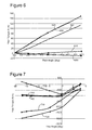
- Figure 6 is a graph illustrating pitch torque versus pitch angle for various deflectors including exemplary embodiments
- FIG. 3 is a schematic diagram of a marine data acquisition system 300 (bird's eye view) according to an exemplary embodiment.
- a vessel 310 tows plural lead-in cables.
- the lead-in cables 320 are configured to be deployed according to a predetermined geometry so that streamers 340 remain substantially parallel at predetermined distances there-between.
- Hydrophones or other receivers (not shown) along the streamers 340 record reflected seismic waves following a shot of a seismic source 330.
- One or more deflectors may be attached to the lead-in cables 320.
- Figure 3 illustrates a deflector 350 attached to each of the lead-in cables 320.
- the first part 410 may have a first slot 416 extending from an end where the first part 410 is joined to the second part 420 toward an opposite end of the first part 410.
- the second part 420 may also have a second slot 426 extending from an end where the second part is joined to the first part to an opposite end of the second part.
- the first slot 416 and the second slot 426 may also be symmetrical relative to the joining axis 430.
- the slots 416 and 426 allow water to pass through the first and second parts. This action improves the stability of the deflector, e.g., reduces stalling.
Landscapes
- Life Sciences & Earth Sciences (AREA)
- Physics & Mathematics (AREA)
- Engineering & Computer Science (AREA)
- General Life Sciences & Earth Sciences (AREA)
- Geophysics (AREA)
- Environmental & Geological Engineering (AREA)
- Geology (AREA)
- Remote Sensing (AREA)
- Oceanography (AREA)
- General Physics & Mathematics (AREA)
- Acoustics & Sound (AREA)
- Chemical & Material Sciences (AREA)
- Combustion & Propulsion (AREA)
- Mechanical Engineering (AREA)
- Ocean & Marine Engineering (AREA)
- Geophysics And Detection Of Objects (AREA)
- Farming Of Fish And Shellfish (AREA)
- Traffic Control Systems (AREA)
Abstract
Description
- Embodiments of the subject matter disclosed herein generally relate to devices and systems used for marine exploration and, more particularly, to deflectors attached to cables that carry seismic instrumentation.
- Marine data acquisition and processing generate a profile (image) of a geophysical structure under the seafloor. While this profile does not provide an accurate location of oil and gas reservoirs, it suggests, to those trained in the field, the presence or absence of these reservoirs. In order to obtain a high-resolution image of the structure under the seafloor, plural techniques and devices are employed to maintain the data acquisition geometry while scanning the targeted area.
- In marine exploration, waves (such as, but not limited to, seismic waves) are directed toward the seabed, and waves reflected back to receivers close to the water surface are used to extract information about the structure and nature of the rock layers underneath the seabed. A vessel usually tows a series of cables connected to a seismic source and/or a streamer that includes the receivers. The vessel tows the cables along a specified path to scan the targeted area. Arranging and maintaining the configuration of these cables (e.g., with minimal drag, the cables remaining at their assigned depth and lateral offset) is desirable. One of the devices employed in order to arrange and maintain the configuration of these cables is a deflector. The deflector is attached to a towing cable and provides a lift force to the cable while towed through the water, to maintain depth and/or lateral separation among the towing cables.
-
Figure 1 illustrates aconventional deflector 10 attached to atowing cable 20. Thedeflector 10 has a flat, rectangular-shaped body 12 and may haveballast bodies 14 and 16 (also known as pods) at ends of thebody 12. Atop ballast body 14 is lighter than abottom ballast body 16 to move the gravity center of thedeflector 10 below a buoyancy center thereof. Thedeflector 10 may also have aslot 18 along thebody 12 to increase the stalling angle. The length of the deflector may be around 2.5 m. Thedeflector 10 is attached to thecable 20 around a middle area of thedeflector 10. - A problem with the conventional deflector is that its angular stability is low, that is, if it rotates (e.g., due to currents) around the towing position, the deflector does not return to the intended position, and, therefore, instead of providing a lift force, drags down the towing cable.
Figures 2A and 2B illustrate this problem. - Thus, it is desired to produce a deflector that has better angular stability such that if it rotates around the towing position, it develops a returning torque that returns the deflector to the intended position.
- One objective achieved in some of the embodiments described in this application is to provide a deflector with improved angular stability for marine survey (i.e., data acquisition) systems. That is, deflectors are configured to develop a restoring torque opposing deviations (pitch, roll and yaw) of the deflector from an intended position.
- According to one exemplary embodiment, there is a deflector configured to be attached to a cable towed by a vessel to carry instrumentation for a marine survey. The deflector has a wing body including a first part joined to a second part to form a swept-back-wing shape, the first part and the second part being substantially coplanar. A first straight line stretching along at least a portion of a front edge of the first part makes a first angle with a second straight line stretching along at least a portion of a front edge of the second part. A third straight line stretching along at least a portion of a trailing edge of the first part makes a second angle with a fourth straight line stretching along at least a portion of a trailing edge of the second part, the first angle and the second angle being non-zero angles.
- According to another exemplary embodiment, there is a marine data acquisition system including towing cables configured to be deployed according to a predetermined geometry behind a towing vessel to carry survey instrumentation and at least one deflector attached to one of the towing cables. The at least one deflector has a wing body including a first part joined to a second part to form a swept-back-wing shape, the first part and the second part being substantially coplanar. A first straight line stretching along at least a portion of a front edge of the first part makes a first angle with a second straight line stretching along at least a portion of a front edge of the second part. A third straight line stretching along at least a portion of a trailing edge of the first part makes a second angle with a fourth straight line stretching along at least a portion of a trailing edge of the second part, the first angle and the second angle being non-zero angles.
- According to another exemplary embodiment, there is a method of controlling the position of one or more components of a marine data acquisition system. The method includes attaching at least one deflector to at least one towing cable configured to be towed behind a vessel to carry marine survey instrumentation. The deflector has a wing body including a first part joined to a second part to form a swept-back-wing shape, the first part and the second part being substantially coplanar. A first straight line stretching along at least a portion of a front edge of the first part makes a first angle with a second straight line stretching along at least a portion of a front edge of the second part. A third straight line stretching along at least a portion of a trailing edge of the first part makes a second angle with a fourth straight line stretching along at least a portion of a trailing edge of the second part, the first angle and the second angle being non-zero angles. The method further includes deploying the towing cable behind the vessel according to a predetermined marine data acquisition geometry.
- The accompanying drawings, which are incorporated in and constitute a part of the specification, illustrate one or more embodiments and, together with the description, explain these embodiments. In the drawings:
-
Figure 1 is a schematic diagram of a conventional deflector; -
Figures 2A and 2B illustrate an unintended roll and yaw of a conventional deflector; -
Figure 3 is a schematic diagram of a marine data acquisition system according to an exemplary embodiment; -
Figure 4 is a deflector according to an exemplary embodiment; -
Figure 5 is a deflector according to another exemplary embodiment; -
Figure 6 is a graph illustrating pitch torque versus pitch angle for various deflectors including exemplary embodiments; -
Figure 7 is a graph illustrating yaw torque versus yaw angle for various deflectors including exemplary embodiments; and -
Figure 8 is a flowchart of a method for towing a source array according to an exemplary embodiment. - The following description of the exemplary embodiments refers to the accompanying drawings. The same reference numbers in different drawings identify the same or similar elements. The following detailed description does not limit the invention. Instead, the scope of the invention is defined by the appended claims. The following embodiments are discussed, for simplicity, with regard to the terminology and structure of a marine survey data acquisition system having one or more cables towed by a vessel. However, the embodiments to be discussed next are not limited to this structure, but they may be applied to other situations in which cables are towed in water at a predetermined depth.
- Reference throughout the specification to "one embodiment" or "an embodiment" means that a particular feature, structure or characteristic described in connection with an embodiment is included in at least one embodiment of the subject matter disclosed. Thus, the appearance of the phrases "in one embodiment" or "in an embodiment" in various places throughout the specification is not necessarily referring to the same embodiment. Further, the particular features, structures or characteristics may be combined in any suitable manner in one or more embodiments.
-
Figure 3 is a schematic diagram of a marine data acquisition system 300 (bird's eye view) according to an exemplary embodiment. Avessel 310 tows plural lead-in cables. The lead-incables 320 are configured to be deployed according to a predetermined geometry so thatstreamers 340 remain substantially parallel at predetermined distances there-between. Hydrophones or other receivers (not shown) along thestreamers 340 record reflected seismic waves following a shot of aseismic source 330. One or more deflectors may be attached to the lead-incables 320.Figure 3 illustrates adeflector 350 attached to each of the lead-incables 320. However, depending on size and placement of the deflector and presence of separation ropes tied between the cables, a deflector may have impact on plural streamers, i.e., fewer deflectors may be deployed. Alternatively, plural deflectors may be mounted along a single cable. The number of streamers illustrated inFigure 3 is exemplary and not intended to be limiting. - A deflector 400 ("wide V-shape deflector") according to an exemplary embodiment is illustrated in
Figure 4 . Thedeflector 400 has a wing body including afirst part 410 joined to asecond part 420 to form a swept-back-wing shape. Thefirst part 410 and thesecond part 420 may be manufactured as a single piece. In one application, the first part is manufactured separately from the second part and it is attached to the second part by using known mechanisms, e.g., welding, gluing, bolts, etc. In one application, thefirst part 410 and thesecond part 420 are substantially flat and coplanar. The first and second part may be symmetrical relative to a joiningaxis 430. - A first straight line along a
front edge 412 of thefirst part 410 makes a first angle α1 with a second straight line along afront edge 422 of thesecond part 420. In one application, the first angle α1 is a non-zero angle. A third straight line along a trailingedge 414 of thefirst part 410 makes a second angle α2 with a fourth straight line along a trailingedge 424 of thesecond part 420. In one application, the second angle α2 is a non-zero angle. The front edge is defined as the edge of the deflector (or wing) that is first along a moving direction (breaks the water) and the trailing edge is the last edge along the moving direction. - In one application, the first angle α1 and the second angle α2 may be substantially equal. The second angle α2 is preferably at least equal to the first angle α1. In another application, the first angle is between 10° and 30°, preferably between 15° and 25°.
- The
first part 410 may have afirst slot 416 extending from an end where thefirst part 410 is joined to thesecond part 420 toward an opposite end of thefirst part 410. Thesecond part 420 may also have asecond slot 426 extending from an end where the second part is joined to the first part to an opposite end of the second part. Thefirst slot 416 and thesecond slot 426 may also be symmetrical relative to the joiningaxis 430. Theslots - The
deflector 400 may include a first ballast body (or "pod") 418 located at an end of thefirst part 410 opposite to the joiningaxis 430, and asecond ballast body 428 located at an end of thesecond part 420 opposite to the joiningaxis 430. Thefirst ballast body 418 and thesecond ballast body 428 may have a shape configured to have low fluid friction when the body moves substantially parallel to the joining axis. In one application, thefirst ballast body 418 is substantially lighter than thesecond ballast body 428. For example, thefirst ballast body 418 may weigh between 10% and 35% of thesecond ballast body 428. In one application, the deflector is neutrally buoyant and the ballast is about 40% of the deflector's weight. The deflector may be made of various materials, e.g., composite, plastic, metal, or a combination thereof. - A deflector 500 ("rounded wide V-shape deflector") according to another exemplary embodiment is illustrated in
Figure 5 . Thedeflector 500 is similar todeflector 400, having a wing body including afirst part 510 joined to asecond part 520 to form a swept-back-wing shape. Thefirst part 510 and thesecond part 520 are substantially flat and coplanar. The first and second part may be symmetrical relative to a joiningaxis 530. A first straight line extends along a part (i.e., fromballast body 518 to point A, for more than 50% of the length thereof to ensure stability) of afront edge 512 of thefirst part 510. A second line extends along a part (i.e., fromballast body 528 to point B, for more than 50% of the length thereof) of afront edge 522 of thesecond part 520. The first line makes a first angle α1 with the second straight line. The sides of the first angle α1 are the first and second straight lines. In this respect, it is noted thatFigure 5 shows the first straight line extending betweenballast body 518 and point A and the second straight line extending between theballast body 528 and point B. The leading edge of the reflector, between points A and B may be curved. - A third straight line extends along a part (i.e., from
ballast body 518 to point C, for more than 50% of the length thereof) of a trailingedge 514 of thefirst part 510. A fourth straight line extends along a part (i.e., fromballast body 528 to point D, for more than 50% of the length thereof) of a trailingedge 524 of thesecond part 520. The third line makes a second angle α2 with the fourth line. The second angle α2 may be a non-zero angle. The first angle α1 and the second angle α2 have similar characteristics with angles α1 and α2 ofdeflector 400. - The first straight line and the second straight line of the
deflector 500 may be connected via a firstcurved portion 540. The third straight line and the fourth straight line of thedeflector 500 may be connected via a secondcurved portion 550. The firstcurved portion 540 may be an arc of a circle (i.e., a portion of the circle's circumference) having a first radius R1 and the secondcurved portion 550 may be an arc of a circle having a second radius R2. The second radius R2 may be smaller than the first radius R1. The first and second curved portions may be parameterized curves (i.e., curves described by a mathematical equation) different from a circle, e.g., a part of an ellipse, or parabola, etc. - The
first part 510 may have afirst slot 516 extending from an end where the first part is joined to the second part toward an opposite end of the first part. Thesecond part 520 may also have asecond slot 526 extending from an end where the second part is joined to the first part to an opposite end of the second part. Thefirst slot 516 and thesecond slot 526 may also be symmetrical relative to the joiningaxis 530. - The
deflector 500 may also include afirst ballast body 518 located at an end of thefirst part 510 opposite to the joiningaxis 530, and asecond ballast body 528 located at an end of thesecond part 520 opposite to the joiningaxis 530. Thefirst ballast body 518 and thesecond ballast body 528 may have similar features as theballast bodies - The deflectors are made of materials compatible with service in both a marine environment and onboard (or in deployment or retrieval from) a vessel. For example, the deflectors may be made of metals and alloys such as duplex steel, stainless steel, aluminum, titanium, plastics, and composites such as fiberglass and carbon fibers.
- Tests and simulations have compared angular stability of the conventional deflector and deflectors similar to the ones illustrated in
Figures 4 and 5 . It has been observed that the pitch and roll effects are strongly correlated. -
Figure 6 is a graph illustrating a pitch torque versus a pitch angle of a deflector,line 610 therein corresponding to the conventional deflector,line 620 corresponding to a deflector similar to the embodiment illustrated inFigure 4 ("wide V-shape") andline 630 corresponding to a deflector similar to the embodiment illustrated inFigure 5 ("rounded wide V-shape"). Additionally, a deflector similar to the wide V-shape deflector but having α2 angle equal to zero ("V-full wing") and a deflector having a rectangular but twisted wing body (attack angle reduced at extremities) have been tested, the test results being illustrated aslines Lines -
Figure 7 is a graph illustrating a yaw torque versus a yaw angle of a deflector,line 710 therein corresponding to the conventional deflector,line 720 corresponding to a wide V-shape deflector (i.e., similar to the embodiment illustrated inFigure 4 ) andline 730 corresponding to a wide rounded V-shape deflector (i.e., similar to the embodiment illustrated inFigure 5 ).Lines - These tests and simulations have demonstrated that both the wide V-shape deflector and the rounded wide V-shape deflector have significantly superior angular stability compared to the conventional deflector. The wide V-shape deflector has best angular stability with a minor loss in performance (around 3% smaller lift force). However, the sharp angle in front of this type of deflector creates a stress concentration location and makes it more difficult to handle. Although the rounded wide V-shape deflector is slightly less stable regarding the yaw angle, this type of deflector does not have the stress concentration problem and it is easier to handle and to manufacture.
- A flow diagram of a
method 800 of controlling a position of one or more components of a marine data acquisition system according to another exemplary embodiment is illustrated inFigure 8 . Themethod 800 includes attaching at least one deflector to at least one towing cable configured to be towed behind a vessel while carrying components of the marine data acquisition system, the deflector having a wing body including a first part joined to a second part to form a swept-back-wing shape, the first part and the second part being substantially coplanar, at S810. Themethod 800 further includes deploying the towing cable behind a vessel according to predetermined marine data acquisition geometry, at S820. The at least one deflector may be similar to any of the embodiments illustrated inFigure 4 and 5 , wherein a first straight line along at least a portion of a front edge of the first part makes a first angle with a second straight line along at least a portion of a front edge of the second part, and a third straight line along at least a portion of a trailing edge of the first part makes a second angle with a fourth straight line along at least a portion of a trailing edge of the second part, the first angle and the second angle being non-zero angles. - One or more of the exemplary embodiments discussed above are related to deflectors attached to a towing cable of a vessel towing a marine data acquisition system. It should be understood that this description is not intended to limit the invention. On the contrary, the exemplary embodiments are intended to cover alternatives, modifications and equivalents, which are included in the spirit and scope of the invention as defined by the appended claims. Further, in the detailed description of the exemplary embodiments, numerous specific details are set forth in order to provide a comprehensive understanding of the claimed invention. However, one skilled in the art would understand that various embodiments may be practiced without such specific details.
- Although the features and elements of the present exemplary embodiments are described in the embodiments in particular combinations, each feature or element can be used alone without the other features and elements of the embodiments or in various combinations with or without other features and elements disclosed herein.
- This written description uses examples of the subject matter disclosed to enable any person skilled in the art to practice the same, including making and using any devices or systems and performing any incorporated methods. The patentable scope of the subject matter is defined by the claims, and may include other examples that occur to those skilled in the art. Such other examples are intended to be within the scope of the claims.
Claims (15)
- A deflector (350, 400, 500) configured to be attached to a cable (320) towed by a vessel (310) and configured to connect to a streamer (340) or a source (330) for a marine survey, the deflector comprising:a wing body (410, 420, 510, 520) including a first part (410, 510) joined to a second part (420, 520) to form a swept-back-wing shape, the first part and the second part being substantially coplanar,whereina first straight line stretching along at least a portion of a front edge (412, 512) of the first part makes a first angle (α1) with a second straight line stretching along at least a portion of a front edge (422, 522) of the second part, anda third straight line stretching along at least a portion of a trailing edge (414, 514) of the first part makes a second angle (α2) with a fourth straight line stretching along at least a portion of a trailing edge (424, 524) of the second part, the first angle and the second angle being non-zero angles.
- The deflector of claim 1, wherein the first angle and the second angle are substantially equal.
- The deflector of claim 1, wherein
the portion of the front edge of the first part along which the first straight line stretches is longer than half of the front edge of the first part,
the portion of the front edge of the second part along which the second straight line stretches is longer than half of the front edge of the second part,
the portion of the trailing edge of the first part along which the third straight line stretches is longer than half of the trailing edge of the first part, and
the portion of the trailing edge of the second part along which the fourth straight line stretches is longer than half of the trailing edge of the second part. - The deflector of claim 1, wherein
the portion of the front edge of the first part along which the first straight line stretches and the portion of the front edge of the second part along which the second straight line stretches are connected via a first curved portion, and
the portion of the trailing edge of the first part along which the third straight line stretches and the portion of the trailing edge of the second part along which the fourth straight line stretches are connected via a second curved portion. - The deflector of claim 4, wherein the first curved portion is an arc of a circle having a first radius and the second curved portion is an arc of a circle having a second radius.
- The deflector of claim 5, wherein the second radius is smaller than the first radius.
- The deflector of claim 1, wherein the first angle is between 15° and 25°.
- The deflector of claim 1, wherein the portion of the front edge of the first part, the portion of the front edge of the second part, the portion of the trailing edge of the first part, and the portion of the trailing edge of the second part, along which the first line, the second line, the third line and the fourth line respectively stretch, extend at least 10% of a length of the first part or of the second part, respectively.
- The deflector of claim 1, further comprising:a first ballast body located at an end of the first part opposite to the joining axis; anda second ballast body located at an end of the second part opposite to the joining axis,whereinthe first ballast body and the second ballast body have a shape configured to have low fluid friction when the body moves substantially parallel to the joining axis, andthe first ballast body is lighter than the second ballast body.
- The deflector of claim 1, wherein the first part has a first slot extending from an end where the first part is joined to the second part toward an opposite end of the first part, and the second part has a second slot extending from an end where the second part is joined to the first part to an opposite end of the second part.
- A marine data acquisition system (300), comprising:towing cables (320) configured to be deployed according to a predetermined geometry behind a towing vessel (310) and configured to connect to a streamer (340) or a source (330); andat least one deflector (350, 400, 500) attached to one of the towing cables (320), the at least one deflector having a wing body (410, 420, 510, 520) including a first part (410, 510) joined to a second part (420, 520) to form a swept-back-wing shape, the first part and the second part being substantially coplanar,whereina first straight line stretching along at least a portion of a front edge (412, 512) of the first part makes a first angle (α1) with a second straight line stretching along at least a portion of a front edge (422, 522) of the second part, anda third straight line stretching along at least a portion of a trailing edge (414, 514) of the first part makes a second angle (α2) with a fourth straight line stretching along at least a portion of a trailing edge (424, 524) of the second part, the first angle and the second angle being non-zero angles.
- The marine data acquisition system of claim 11, wherein at least one of the following conditions is met:(A) the first angle and the second angle are substantially equal;(B) the first angle is between 15° and 25°;(C) the at least one wing further has a first ballast body located at an end of the first part opposite to another end thereof where the first part is connected to the second part, and a second ballast body located at an end of the second part opposite to another end thereof where the second part is connected to the first part, the first ballast body and the second ballast body having a shape configured to have low fluid friction when the wing body moves substantially parallel to the axis, and the first ballast body being lighter than the second ballast body; and(D) the first part has a first slot, and the second part has a second slot, the first slot and the second flow allowing a fluid to pass through the wing body.
- The marine data acquisition system of claim 11, wherein the wing body does not have a boomerang shape.
- The marine data acquisition system of claim 11, wherein the portion of the front edge of the first part along which the first straight line stretches and the portion of the front edge of the second part along which the second straight line stretches are connected via a first curved portion, and the portion of the trailing edge of the first part along which the third straight line stretches and the portion of the trailing edge of the second part along which the fourth straight line stretches are connected via a second curved portion;
- A method (800) of controlling position of one or more components of a marine data acquisition system, the method comprising:attaching (S810) a deflector to a towing cable configured to be towed behind a vessel, the deflector having a wing body including a first part joined to a second part to form a swept-back-wing shape, the first part and the second part being substantially coplanar; anddeploying (S820) the towing cable behind the vessel according to a predetermined marine data acquisition geometry,whereina first straight line stretching along at least a portion of a front edge (412, 512) of the first part makes a first angle (α1) with a second straight line stretching along at least a portion of a front edge (422, 522) of the second part, anda third straight line stretching along at least a portion of a trailing edge (414, 514) of the first part makes a second angle (α2) with a fourth straight line stretching along at least a portion of a trailing edge (424, 524) of the second part, the first angle and the second angle being non-zero angles.
Applications Claiming Priority (1)
| Application Number | Priority Date | Filing Date | Title |
|---|---|---|---|
| US201261611643P | 2012-03-16 | 2012-03-16 |
Publications (2)
| Publication Number | Publication Date |
|---|---|
| EP2639150A1 true EP2639150A1 (en) | 2013-09-18 |
| EP2639150B1 EP2639150B1 (en) | 2018-11-21 |
Family
ID=47915466
Family Applications (1)
| Application Number | Title | Priority Date | Filing Date |
|---|---|---|---|
| EP13159580.3A Not-in-force EP2639150B1 (en) | 2012-03-16 | 2013-03-15 | Deflector for marine data acquisition system |
Country Status (5)
| Country | Link |
|---|---|
| US (1) | US9221524B2 (en) |
| EP (1) | EP2639150B1 (en) |
| BR (1) | BR102013006421A2 (en) |
| CA (1) | CA2809616A1 (en) |
| MX (1) | MX339117B (en) |
Families Citing this family (5)
| Publication number | Priority date | Publication date | Assignee | Title |
|---|---|---|---|---|
| CA2856316C (en) | 2011-10-28 | 2020-07-28 | Global Dynamics Incorporated | Steerable fairing string |
| US9676454B2 (en) * | 2013-03-04 | 2017-06-13 | Cgg Services Sas | Deflector for marine seismic survey system |
| US10488541B2 (en) | 2015-10-15 | 2019-11-26 | Ion Geophysical Corporation | Dynamically controlled foil systems and methods |
| EP3417318B1 (en) | 2016-02-16 | 2020-09-30 | GX Technology Canada Ltd. | Ribbon foil depressor |
| CN113382922B (en) | 2018-10-09 | 2024-07-19 | Gx技术加拿大有限公司 | Modular airfoil system for towed ocean arrays |
Citations (5)
| Publication number | Priority date | Publication date | Assignee | Title |
|---|---|---|---|---|
| US2980052A (en) * | 1954-07-27 | 1961-04-18 | Leo F Fehlner | Paravane |
| GB2223728A (en) * | 1988-10-11 | 1990-04-18 | Thomson Csf | Hydrodynamic depressor |
| US5000110A (en) * | 1989-09-27 | 1991-03-19 | Moore Barry B | Towline depressor |
| US5263430A (en) * | 1990-08-26 | 1993-11-23 | Monfort Robert W | Aquatic amusement device |
| US6820568B1 (en) * | 1999-06-15 | 2004-11-23 | Bernard Aubrey Shattock | Hydrofoil apparatus |
Family Cites Families (9)
| Publication number | Priority date | Publication date | Assignee | Title |
|---|---|---|---|---|
| US2960960A (en) * | 1954-07-27 | 1960-11-22 | Leo F Fehlner | Paravane |
| US3137264A (en) * | 1961-11-15 | 1964-06-16 | Braincon Corp | Underwater towed vehicle |
| USD273127S (en) * | 1980-08-13 | 1984-03-20 | Meister Robert L | Swimmer's towable diving plane |
| USD272259S (en) * | 1980-10-06 | 1984-01-17 | Meister Robert L | Diver's towable diving plane |
| USD308358S (en) * | 1986-08-12 | 1990-06-05 | Moore Barry B | Towline depressor |
| DE69302513T2 (en) * | 1992-03-24 | 1996-09-19 | Geco As | Otter device |
| US8100078B2 (en) * | 2004-06-16 | 2012-01-24 | Westerngeco L.L.C. | Steerable hydrofoil |
| EP2370838A4 (en) | 2008-12-12 | 2017-03-08 | CGG Veritas Services (U.S.) Inc. | Seismic array towing system |
| US8976623B2 (en) * | 2011-07-05 | 2015-03-10 | POS Geophysical AS | Towing methods and systems for geophysical surveys |
-
2012
- 2012-09-07 US US13/606,772 patent/US9221524B2/en not_active Expired - Fee Related
-
2013
- 2013-03-13 MX MX2013002873A patent/MX339117B/en active IP Right Grant
- 2013-03-14 CA CA2809616A patent/CA2809616A1/en not_active Abandoned
- 2013-03-15 EP EP13159580.3A patent/EP2639150B1/en not_active Not-in-force
- 2013-03-18 BR BRBR102013006421-1A patent/BR102013006421A2/en not_active Application Discontinuation
Patent Citations (5)
| Publication number | Priority date | Publication date | Assignee | Title |
|---|---|---|---|---|
| US2980052A (en) * | 1954-07-27 | 1961-04-18 | Leo F Fehlner | Paravane |
| GB2223728A (en) * | 1988-10-11 | 1990-04-18 | Thomson Csf | Hydrodynamic depressor |
| US5000110A (en) * | 1989-09-27 | 1991-03-19 | Moore Barry B | Towline depressor |
| US5263430A (en) * | 1990-08-26 | 1993-11-23 | Monfort Robert W | Aquatic amusement device |
| US6820568B1 (en) * | 1999-06-15 | 2004-11-23 | Bernard Aubrey Shattock | Hydrofoil apparatus |
Also Published As
| Publication number | Publication date |
|---|---|
| CA2809616A1 (en) | 2013-09-16 |
| MX2013002873A (en) | 2013-10-14 |
| BR102013006421A2 (en) | 2015-06-09 |
| MX339117B (en) | 2016-05-11 |
| US20130239864A1 (en) | 2013-09-19 |
| US9221524B2 (en) | 2015-12-29 |
| EP2639150B1 (en) | 2018-11-21 |
Similar Documents
| Publication | Publication Date | Title |
|---|---|---|
| FR2977680B1 (en) | TOWING METHODS AND SYSTEMS FOR GEOPHYSICAL RESEARCH | |
| US9244184B2 (en) | Rigid-stem lead-in method and system | |
| US9221524B2 (en) | Deflector for marine data acquisition system | |
| US11325680B2 (en) | Adjustable buoyancy foil | |
| US9341730B2 (en) | Steering submersible float for seismic sources and related methods | |
| WO2010009249A2 (en) | Interconnecting tow members of a marine seismic system | |
| DK2724928T3 (en) | Joint deflector for seismic marine survey system | |
| US8997675B2 (en) | Paravane increased lift, towing system and method | |
| US20140078862A1 (en) | Streamer spread with reduced drag | |
| CN105899973A (en) | Wide source seismic towing configuration | |
| US9676454B2 (en) | Deflector for marine seismic survey system | |
| WO2015007798A2 (en) | Lead-in cable with replaceable portion and method | |
| EP2909655B1 (en) | Flared pseudo-random spiral marine acquisition | |
| EP2955548A1 (en) | Multi-sectional separation ropes for streamers in towed seismic and a method for generating a separation rope | |
| US20180059271A1 (en) | Transverse vibration attenuation mechanism and method for marine seismic acquisition system | |
| NO20111552A1 (en) | A towable and steerable marine seismic source array | |
| US9140813B2 (en) | Method and foldable support assembly | |
| KR102889797B1 (en) | Towing module for submarine detection streamer and submarine cable depth and position detection system including same | |
| GB2513468A (en) | Wing for wide tow of geophysical survey sources | |
| Bartel et al. | Design of a Subsurface Moored Acoustic Array in Deep Water | |
| EP2770346A2 (en) | Far-Field Detection Device, System and Method |
Legal Events
| Date | Code | Title | Description |
|---|---|---|---|
| PUAI | Public reference made under article 153(3) epc to a published international application that has entered the european phase |
Free format text: ORIGINAL CODE: 0009012 |
|
| AK | Designated contracting states |
Kind code of ref document: A1 Designated state(s): AL AT BE BG CH CY CZ DE DK EE ES FI FR GB GR HR HU IE IS IT LI LT LU LV MC MK MT NL NO PL PT RO RS SE SI SK SM TR |
|
| AX | Request for extension of the european patent |
Extension state: BA ME |
|
| 17P | Request for examination filed |
Effective date: 20140306 |
|
| RBV | Designated contracting states (corrected) |
Designated state(s): AL AT BE BG CH CY CZ DE DK EE ES FI FR GB GR HR HU IE IS IT LI LT LU LV MC MK MT NL NO PL PT RO RS SE SI SK SM TR |
|
| RAP1 | Party data changed (applicant data changed or rights of an application transferred) |
Owner name: CGG SERVICES SA |
|
| STAA | Information on the status of an ep patent application or granted ep patent |
Free format text: STATUS: EXAMINATION IS IN PROGRESS |
|
| 17Q | First examination report despatched |
Effective date: 20171115 |
|
| GRAP | Despatch of communication of intention to grant a patent |
Free format text: ORIGINAL CODE: EPIDOSNIGR1 |
|
| STAA | Information on the status of an ep patent application or granted ep patent |
Free format text: STATUS: GRANT OF PATENT IS INTENDED |
|
| INTG | Intention to grant announced |
Effective date: 20180706 |
|
| GRAS | Grant fee paid |
Free format text: ORIGINAL CODE: EPIDOSNIGR3 |
|
| GRAA | (expected) grant |
Free format text: ORIGINAL CODE: 0009210 |
|
| STAA | Information on the status of an ep patent application or granted ep patent |
Free format text: STATUS: THE PATENT HAS BEEN GRANTED |
|
| RAP1 | Party data changed (applicant data changed or rights of an application transferred) |
Owner name: CGG SERVICES SAS |
|
| AK | Designated contracting states |
Kind code of ref document: B1 Designated state(s): AL AT BE BG CH CY CZ DE DK EE ES FI FR GB GR HR HU IE IS IT LI LT LU LV MC MK MT NL NO PL PT RO RS SE SI SK SM TR |
|
| REG | Reference to a national code |
Ref country code: CH Ref legal event code: EP |
|
| REG | Reference to a national code |
Ref country code: IE Ref legal event code: FG4D |
|
| REG | Reference to a national code |
Ref country code: DE Ref legal event code: R096 Ref document number: 602013046973 Country of ref document: DE |
|
| REG | Reference to a national code |
Ref country code: AT Ref legal event code: REF Ref document number: 1067230 Country of ref document: AT Kind code of ref document: T Effective date: 20181215 |
|
| REG | Reference to a national code |
Ref country code: NL Ref legal event code: MP Effective date: 20181121 |
|
| REG | Reference to a national code |
Ref country code: AT Ref legal event code: MK05 Ref document number: 1067230 Country of ref document: AT Kind code of ref document: T Effective date: 20181121 |
|
| REG | Reference to a national code |
Ref country code: NO Ref legal event code: T2 Effective date: 20181121 |
|
| PG25 | Lapsed in a contracting state [announced via postgrant information from national office to epo] |
Ref country code: LT Free format text: LAPSE BECAUSE OF FAILURE TO SUBMIT A TRANSLATION OF THE DESCRIPTION OR TO PAY THE FEE WITHIN THE PRESCRIBED TIME-LIMIT Effective date: 20181121 Ref country code: HR Free format text: LAPSE BECAUSE OF FAILURE TO SUBMIT A TRANSLATION OF THE DESCRIPTION OR TO PAY THE FEE WITHIN THE PRESCRIBED TIME-LIMIT Effective date: 20181121 Ref country code: BG Free format text: LAPSE BECAUSE OF FAILURE TO SUBMIT A TRANSLATION OF THE DESCRIPTION OR TO PAY THE FEE WITHIN THE PRESCRIBED TIME-LIMIT Effective date: 20190221 Ref country code: AT Free format text: LAPSE BECAUSE OF FAILURE TO SUBMIT A TRANSLATION OF THE DESCRIPTION OR TO PAY THE FEE WITHIN THE PRESCRIBED TIME-LIMIT Effective date: 20181121 Ref country code: ES Free format text: LAPSE BECAUSE OF FAILURE TO SUBMIT A TRANSLATION OF THE DESCRIPTION OR TO PAY THE FEE WITHIN THE PRESCRIBED TIME-LIMIT Effective date: 20181121 Ref country code: IS Free format text: LAPSE BECAUSE OF FAILURE TO SUBMIT A TRANSLATION OF THE DESCRIPTION OR TO PAY THE FEE WITHIN THE PRESCRIBED TIME-LIMIT Effective date: 20190321 Ref country code: LV Free format text: LAPSE BECAUSE OF FAILURE TO SUBMIT A TRANSLATION OF THE DESCRIPTION OR TO PAY THE FEE WITHIN THE PRESCRIBED TIME-LIMIT Effective date: 20181121 Ref country code: FI Free format text: LAPSE BECAUSE OF FAILURE TO SUBMIT A TRANSLATION OF THE DESCRIPTION OR TO PAY THE FEE WITHIN THE PRESCRIBED TIME-LIMIT Effective date: 20181121 |
|
| PGFP | Annual fee paid to national office [announced via postgrant information from national office to epo] |
Ref country code: GB Payment date: 20190320 Year of fee payment: 7 Ref country code: NO Payment date: 20190325 Year of fee payment: 7 Ref country code: FR Payment date: 20190322 Year of fee payment: 7 |
|
| PG25 | Lapsed in a contracting state [announced via postgrant information from national office to epo] |
Ref country code: AL Free format text: LAPSE BECAUSE OF FAILURE TO SUBMIT A TRANSLATION OF THE DESCRIPTION OR TO PAY THE FEE WITHIN THE PRESCRIBED TIME-LIMIT Effective date: 20181121 Ref country code: SE Free format text: LAPSE BECAUSE OF FAILURE TO SUBMIT A TRANSLATION OF THE DESCRIPTION OR TO PAY THE FEE WITHIN THE PRESCRIBED TIME-LIMIT Effective date: 20181121 Ref country code: RS Free format text: LAPSE BECAUSE OF FAILURE TO SUBMIT A TRANSLATION OF THE DESCRIPTION OR TO PAY THE FEE WITHIN THE PRESCRIBED TIME-LIMIT Effective date: 20181121 Ref country code: PT Free format text: LAPSE BECAUSE OF FAILURE TO SUBMIT A TRANSLATION OF THE DESCRIPTION OR TO PAY THE FEE WITHIN THE PRESCRIBED TIME-LIMIT Effective date: 20190321 Ref country code: GR Free format text: LAPSE BECAUSE OF FAILURE TO SUBMIT A TRANSLATION OF THE DESCRIPTION OR TO PAY THE FEE WITHIN THE PRESCRIBED TIME-LIMIT Effective date: 20190222 Ref country code: NL Free format text: LAPSE BECAUSE OF FAILURE TO SUBMIT A TRANSLATION OF THE DESCRIPTION OR TO PAY THE FEE WITHIN THE PRESCRIBED TIME-LIMIT Effective date: 20181121 |
|
| PG25 | Lapsed in a contracting state [announced via postgrant information from national office to epo] |
Ref country code: DK Free format text: LAPSE BECAUSE OF FAILURE TO SUBMIT A TRANSLATION OF THE DESCRIPTION OR TO PAY THE FEE WITHIN THE PRESCRIBED TIME-LIMIT Effective date: 20181121 Ref country code: PL Free format text: LAPSE BECAUSE OF FAILURE TO SUBMIT A TRANSLATION OF THE DESCRIPTION OR TO PAY THE FEE WITHIN THE PRESCRIBED TIME-LIMIT Effective date: 20181121 Ref country code: IT Free format text: LAPSE BECAUSE OF FAILURE TO SUBMIT A TRANSLATION OF THE DESCRIPTION OR TO PAY THE FEE WITHIN THE PRESCRIBED TIME-LIMIT Effective date: 20181121 Ref country code: CZ Free format text: LAPSE BECAUSE OF FAILURE TO SUBMIT A TRANSLATION OF THE DESCRIPTION OR TO PAY THE FEE WITHIN THE PRESCRIBED TIME-LIMIT Effective date: 20181121 |
|
| REG | Reference to a national code |
Ref country code: DE Ref legal event code: R097 Ref document number: 602013046973 Country of ref document: DE |
|
| PG25 | Lapsed in a contracting state [announced via postgrant information from national office to epo] |
Ref country code: RO Free format text: LAPSE BECAUSE OF FAILURE TO SUBMIT A TRANSLATION OF THE DESCRIPTION OR TO PAY THE FEE WITHIN THE PRESCRIBED TIME-LIMIT Effective date: 20181121 Ref country code: EE Free format text: LAPSE BECAUSE OF FAILURE TO SUBMIT A TRANSLATION OF THE DESCRIPTION OR TO PAY THE FEE WITHIN THE PRESCRIBED TIME-LIMIT Effective date: 20181121 Ref country code: SM Free format text: LAPSE BECAUSE OF FAILURE TO SUBMIT A TRANSLATION OF THE DESCRIPTION OR TO PAY THE FEE WITHIN THE PRESCRIBED TIME-LIMIT Effective date: 20181121 Ref country code: SK Free format text: LAPSE BECAUSE OF FAILURE TO SUBMIT A TRANSLATION OF THE DESCRIPTION OR TO PAY THE FEE WITHIN THE PRESCRIBED TIME-LIMIT Effective date: 20181121 |
|
| PLBE | No opposition filed within time limit |
Free format text: ORIGINAL CODE: 0009261 |
|
| STAA | Information on the status of an ep patent application or granted ep patent |
Free format text: STATUS: NO OPPOSITION FILED WITHIN TIME LIMIT |
|
| REG | Reference to a national code |
Ref country code: DE Ref legal event code: R119 Ref document number: 602013046973 Country of ref document: DE |
|
| 26N | No opposition filed |
Effective date: 20190822 |
|
| PG25 | Lapsed in a contracting state [announced via postgrant information from national office to epo] |
Ref country code: MC Free format text: LAPSE BECAUSE OF FAILURE TO SUBMIT A TRANSLATION OF THE DESCRIPTION OR TO PAY THE FEE WITHIN THE PRESCRIBED TIME-LIMIT Effective date: 20181121 Ref country code: SI Free format text: LAPSE BECAUSE OF FAILURE TO SUBMIT A TRANSLATION OF THE DESCRIPTION OR TO PAY THE FEE WITHIN THE PRESCRIBED TIME-LIMIT Effective date: 20181121 |
|
| REG | Reference to a national code |
Ref country code: CH Ref legal event code: PL |
|
| PG25 | Lapsed in a contracting state [announced via postgrant information from national office to epo] |
Ref country code: LU Free format text: LAPSE BECAUSE OF NON-PAYMENT OF DUE FEES Effective date: 20190315 |
|
| REG | Reference to a national code |
Ref country code: BE Ref legal event code: MM Effective date: 20190331 |
|
| PG25 | Lapsed in a contracting state [announced via postgrant information from national office to epo] |
Ref country code: DE Free format text: LAPSE BECAUSE OF NON-PAYMENT OF DUE FEES Effective date: 20191001 Ref country code: LI Free format text: LAPSE BECAUSE OF NON-PAYMENT OF DUE FEES Effective date: 20190331 Ref country code: CH Free format text: LAPSE BECAUSE OF NON-PAYMENT OF DUE FEES Effective date: 20190331 Ref country code: IE Free format text: LAPSE BECAUSE OF NON-PAYMENT OF DUE FEES Effective date: 20190315 |
|
| PG25 | Lapsed in a contracting state [announced via postgrant information from national office to epo] |
Ref country code: BE Free format text: LAPSE BECAUSE OF NON-PAYMENT OF DUE FEES Effective date: 20190331 |
|
| PG25 | Lapsed in a contracting state [announced via postgrant information from national office to epo] |
Ref country code: TR Free format text: LAPSE BECAUSE OF FAILURE TO SUBMIT A TRANSLATION OF THE DESCRIPTION OR TO PAY THE FEE WITHIN THE PRESCRIBED TIME-LIMIT Effective date: 20181121 |
|
| PG25 | Lapsed in a contracting state [announced via postgrant information from national office to epo] |
Ref country code: MT Free format text: LAPSE BECAUSE OF NON-PAYMENT OF DUE FEES Effective date: 20190315 |
|
| REG | Reference to a national code |
Ref country code: NO Ref legal event code: MMEP |
|
| PG25 | Lapsed in a contracting state [announced via postgrant information from national office to epo] |
Ref country code: FR Free format text: LAPSE BECAUSE OF NON-PAYMENT OF DUE FEES Effective date: 20200331 Ref country code: NO Free format text: LAPSE BECAUSE OF NON-PAYMENT OF DUE FEES Effective date: 20200331 |
|
| GBPC | Gb: european patent ceased through non-payment of renewal fee |
Effective date: 20200315 |
|
| PG25 | Lapsed in a contracting state [announced via postgrant information from national office to epo] |
Ref country code: GB Free format text: LAPSE BECAUSE OF NON-PAYMENT OF DUE FEES Effective date: 20200315 |
|
| PG25 | Lapsed in a contracting state [announced via postgrant information from national office to epo] |
Ref country code: CY Free format text: LAPSE BECAUSE OF FAILURE TO SUBMIT A TRANSLATION OF THE DESCRIPTION OR TO PAY THE FEE WITHIN THE PRESCRIBED TIME-LIMIT Effective date: 20181121 |
|
| PG25 | Lapsed in a contracting state [announced via postgrant information from national office to epo] |
Ref country code: HU Free format text: LAPSE BECAUSE OF FAILURE TO SUBMIT A TRANSLATION OF THE DESCRIPTION OR TO PAY THE FEE WITHIN THE PRESCRIBED TIME-LIMIT; INVALID AB INITIO Effective date: 20130315 |
|
| PG25 | Lapsed in a contracting state [announced via postgrant information from national office to epo] |
Ref country code: MK Free format text: LAPSE BECAUSE OF FAILURE TO SUBMIT A TRANSLATION OF THE DESCRIPTION OR TO PAY THE FEE WITHIN THE PRESCRIBED TIME-LIMIT Effective date: 20181121 |