EP2639004A1 - Schaufelkranzsegment mit Ringraumbegrenzungsfläche mit einem welligen Höhenprofil sowie Verfahren zur Herstellung desselben - Google Patents
Schaufelkranzsegment mit Ringraumbegrenzungsfläche mit einem welligen Höhenprofil sowie Verfahren zur Herstellung desselben Download PDFInfo
- Publication number
- EP2639004A1 EP2639004A1 EP12159601.9A EP12159601A EP2639004A1 EP 2639004 A1 EP2639004 A1 EP 2639004A1 EP 12159601 A EP12159601 A EP 12159601A EP 2639004 A1 EP2639004 A1 EP 2639004A1
- Authority
- EP
- European Patent Office
- Prior art keywords
- blade ring
- machined
- blade
- electrode
- workpiece
- Prior art date
- Legal status (The legal status is an assumption and is not a legal conclusion. Google has not performed a legal analysis and makes no representation as to the accuracy of the status listed.)
- Granted
Links
- 238000004519 manufacturing process Methods 0.000 title description 2
- 238000003754 machining Methods 0.000 claims abstract description 24
- 238000000034 method Methods 0.000 claims abstract description 17
- 239000000463 material Substances 0.000 claims description 19
- 230000002093 peripheral effect Effects 0.000 claims description 9
- 230000003628 erosive effect Effects 0.000 claims description 2
- 238000007373 indentation Methods 0.000 claims description 2
- 239000006181 electrochemical material Substances 0.000 claims 1
- 230000001788 irregular Effects 0.000 abstract 1
- 238000005242 forging Methods 0.000 description 4
- 230000006978 adaptation Effects 0.000 description 3
- 230000015572 biosynthetic process Effects 0.000 description 3
- 238000012876 topography Methods 0.000 description 3
- 229910010038 TiAl Inorganic materials 0.000 description 2
- 238000009760 electrical discharge machining Methods 0.000 description 2
- 238000007493 shaping process Methods 0.000 description 2
- 238000005266 casting Methods 0.000 description 1
- 230000000295 complement effect Effects 0.000 description 1
- 230000001419 dependent effect Effects 0.000 description 1
- 230000000694 effects Effects 0.000 description 1
- 239000003792 electrolyte Substances 0.000 description 1
- 239000002001 electrolyte material Substances 0.000 description 1
- 238000005516 engineering process Methods 0.000 description 1
- 239000003562 lightweight material Substances 0.000 description 1
- 238000012986 modification Methods 0.000 description 1
- 230000004048 modification Effects 0.000 description 1
- 238000003672 processing method Methods 0.000 description 1
- 239000000126 substance Substances 0.000 description 1
Images


Classifications
-
- B—PERFORMING OPERATIONS; TRANSPORTING
- B23—MACHINE TOOLS; METAL-WORKING NOT OTHERWISE PROVIDED FOR
- B23H—WORKING OF METAL BY THE ACTION OF A HIGH CONCENTRATION OF ELECTRIC CURRENT ON A WORKPIECE USING AN ELECTRODE WHICH TAKES THE PLACE OF A TOOL; SUCH WORKING COMBINED WITH OTHER FORMS OF WORKING OF METAL
- B23H9/00—Machining specially adapted for treating particular metal objects or for obtaining special effects or results on metal objects
- B23H9/10—Working turbine blades or nozzles
-
- B—PERFORMING OPERATIONS; TRANSPORTING
- B23—MACHINE TOOLS; METAL-WORKING NOT OTHERWISE PROVIDED FOR
- B23H—WORKING OF METAL BY THE ACTION OF A HIGH CONCENTRATION OF ELECTRIC CURRENT ON A WORKPIECE USING AN ELECTRODE WHICH TAKES THE PLACE OF A TOOL; SUCH WORKING COMBINED WITH OTHER FORMS OF WORKING OF METAL
- B23H3/00—Electrochemical machining, i.e. removing metal by passing current between an electrode and a workpiece in the presence of an electrolyte
-
- B—PERFORMING OPERATIONS; TRANSPORTING
- B23—MACHINE TOOLS; METAL-WORKING NOT OTHERWISE PROVIDED FOR
- B23P—METAL-WORKING NOT OTHERWISE PROVIDED FOR; COMBINED OPERATIONS; UNIVERSAL MACHINE TOOLS
- B23P15/00—Making specific metal objects by operations not covered by a single other subclass or a group in this subclass
- B23P15/02—Making specific metal objects by operations not covered by a single other subclass or a group in this subclass turbine or like blades from one piece
-
- C—CHEMISTRY; METALLURGY
- C25—ELECTROLYTIC OR ELECTROPHORETIC PROCESSES; APPARATUS THEREFOR
- C25F—PROCESSES FOR THE ELECTROLYTIC REMOVAL OF MATERIALS FROM OBJECTS; APPARATUS THEREFOR
- C25F3/00—Electrolytic etching or polishing
-
- F—MECHANICAL ENGINEERING; LIGHTING; HEATING; WEAPONS; BLASTING
- F01—MACHINES OR ENGINES IN GENERAL; ENGINE PLANTS IN GENERAL; STEAM ENGINES
- F01D—NON-POSITIVE DISPLACEMENT MACHINES OR ENGINES, e.g. STEAM TURBINES
- F01D25/00—Component parts, details, or accessories, not provided for in, or of interest apart from, other groups
- F01D25/28—Supporting or mounting arrangements, e.g. for turbine casing
-
- F—MECHANICAL ENGINEERING; LIGHTING; HEATING; WEAPONS; BLASTING
- F01—MACHINES OR ENGINES IN GENERAL; ENGINE PLANTS IN GENERAL; STEAM ENGINES
- F01D—NON-POSITIVE DISPLACEMENT MACHINES OR ENGINES, e.g. STEAM TURBINES
- F01D5/00—Blades; Blade-carrying members; Heating, heat-insulating, cooling or antivibration means on the blades or the members
- F01D5/02—Blade-carrying members, e.g. rotors
-
- F—MECHANICAL ENGINEERING; LIGHTING; HEATING; WEAPONS; BLASTING
- F01—MACHINES OR ENGINES IN GENERAL; ENGINE PLANTS IN GENERAL; STEAM ENGINES
- F01D—NON-POSITIVE DISPLACEMENT MACHINES OR ENGINES, e.g. STEAM TURBINES
- F01D5/00—Blades; Blade-carrying members; Heating, heat-insulating, cooling or antivibration means on the blades or the members
- F01D5/12—Blades
- F01D5/14—Form or construction
- F01D5/141—Shape, i.e. outer, aerodynamic form
- F01D5/142—Shape, i.e. outer, aerodynamic form of the blades of successive rotor or stator blade-rows
- F01D5/143—Contour of the outer or inner working fluid flow path wall, i.e. shroud or hub contour
-
- F—MECHANICAL ENGINEERING; LIGHTING; HEATING; WEAPONS; BLASTING
- F01—MACHINES OR ENGINES IN GENERAL; ENGINE PLANTS IN GENERAL; STEAM ENGINES
- F01D—NON-POSITIVE DISPLACEMENT MACHINES OR ENGINES, e.g. STEAM TURBINES
- F01D5/00—Blades; Blade-carrying members; Heating, heat-insulating, cooling or antivibration means on the blades or the members
- F01D5/12—Blades
- F01D5/22—Blade-to-blade connections, e.g. for damping vibrations
- F01D5/225—Blade-to-blade connections, e.g. for damping vibrations by shrouding
-
- F—MECHANICAL ENGINEERING; LIGHTING; HEATING; WEAPONS; BLASTING
- F05—INDEXING SCHEMES RELATING TO ENGINES OR PUMPS IN VARIOUS SUBCLASSES OF CLASSES F01-F04
- F05B—INDEXING SCHEME RELATING TO WIND, SPRING, WEIGHT, INERTIA OR LIKE MOTORS, TO MACHINES OR ENGINES FOR LIQUIDS COVERED BY SUBCLASSES F03B, F03D AND F03G
- F05B2230/00—Manufacture
- F05B2230/10—Manufacture by removing material
- F05B2230/101—Manufacture by removing material by electrochemical methods
-
- F—MECHANICAL ENGINEERING; LIGHTING; HEATING; WEAPONS; BLASTING
- F05—INDEXING SCHEMES RELATING TO ENGINES OR PUMPS IN VARIOUS SUBCLASSES OF CLASSES F01-F04
- F05D—INDEXING SCHEME FOR ASPECTS RELATING TO NON-POSITIVE-DISPLACEMENT MACHINES OR ENGINES, GAS-TURBINES OR JET-PROPULSION PLANTS
- F05D2220/00—Application
- F05D2220/30—Application in turbines
- F05D2220/32—Application in turbines in gas turbines
- F05D2220/323—Application in turbines in gas turbines for aircraft propulsion, e.g. jet engines
-
- F—MECHANICAL ENGINEERING; LIGHTING; HEATING; WEAPONS; BLASTING
- F05—INDEXING SCHEMES RELATING TO ENGINES OR PUMPS IN VARIOUS SUBCLASSES OF CLASSES F01-F04
- F05D—INDEXING SCHEME FOR ASPECTS RELATING TO NON-POSITIVE-DISPLACEMENT MACHINES OR ENGINES, GAS-TURBINES OR JET-PROPULSION PLANTS
- F05D2230/00—Manufacture
- F05D2230/10—Manufacture by removing material
-
- F—MECHANICAL ENGINEERING; LIGHTING; HEATING; WEAPONS; BLASTING
- F05—INDEXING SCHEMES RELATING TO ENGINES OR PUMPS IN VARIOUS SUBCLASSES OF CLASSES F01-F04
- F05D—INDEXING SCHEME FOR ASPECTS RELATING TO NON-POSITIVE-DISPLACEMENT MACHINES OR ENGINES, GAS-TURBINES OR JET-PROPULSION PLANTS
- F05D2230/00—Manufacture
- F05D2230/10—Manufacture by removing material
- F05D2230/11—Manufacture by removing material by electrochemical methods
-
- F—MECHANICAL ENGINEERING; LIGHTING; HEATING; WEAPONS; BLASTING
- F05—INDEXING SCHEMES RELATING TO ENGINES OR PUMPS IN VARIOUS SUBCLASSES OF CLASSES F01-F04
- F05D—INDEXING SCHEME FOR ASPECTS RELATING TO NON-POSITIVE-DISPLACEMENT MACHINES OR ENGINES, GAS-TURBINES OR JET-PROPULSION PLANTS
- F05D2250/00—Geometry
- F05D2250/20—Three-dimensional
-
- F—MECHANICAL ENGINEERING; LIGHTING; HEATING; WEAPONS; BLASTING
- F05—INDEXING SCHEMES RELATING TO ENGINES OR PUMPS IN VARIOUS SUBCLASSES OF CLASSES F01-F04
- F05D—INDEXING SCHEME FOR ASPECTS RELATING TO NON-POSITIVE-DISPLACEMENT MACHINES OR ENGINES, GAS-TURBINES OR JET-PROPULSION PLANTS
- F05D2250/00—Geometry
- F05D2250/60—Structure; Surface texture
- F05D2250/61—Structure; Surface texture corrugated
- F05D2250/611—Structure; Surface texture corrugated undulated
-
- Y—GENERAL TAGGING OF NEW TECHNOLOGICAL DEVELOPMENTS; GENERAL TAGGING OF CROSS-SECTIONAL TECHNOLOGIES SPANNING OVER SEVERAL SECTIONS OF THE IPC; TECHNICAL SUBJECTS COVERED BY FORMER USPC CROSS-REFERENCE ART COLLECTIONS [XRACs] AND DIGESTS
- Y02—TECHNOLOGIES OR APPLICATIONS FOR MITIGATION OR ADAPTATION AGAINST CLIMATE CHANGE
- Y02T—CLIMATE CHANGE MITIGATION TECHNOLOGIES RELATED TO TRANSPORTATION
- Y02T50/00—Aeronautics or air transport
- Y02T50/60—Efficient propulsion technologies, e.g. for aircraft
Definitions
- the present invention relates to a method for machining a workpiece, wherein an electrode is arranged at a distance from the workpiece to be machined and is moved linearly in the direction of the workpiece to be machined to cause material to be removed from the workpiece during the approach to the workpiece is at least one end or a portion of an end of a surface to be machined of the workpiece obliquely to a leading edge of the surface processing electrode and the electrode is moved at least partially with the electrode surface parallel to the surface to be machined, so that when approaching Furthermore, the present invention relates to blade rim segments for a blade ring of a turbomachine and a corresponding blade ring, wherein the blade ring segments with the above-mentioned methods are produced.
- blade rings may be used in which a plurality of blade rim segments, each having at least one airfoil and an inner and / or outer shroud are assembled into a blade ring.
- the blade profiles of the individual blade ring segments define between them an annular space through which flows the working gas, wherein the annular space is limited by the shrouds and the shrouds have corresponding annular space boundary surfaces.
- Blade ring segments are made in the prior art by casting or forging, in particular with newer, lightweight materials, such as TiAl materials, a forging to increase the strength is required.
- a forging to increase the strength is required.
- electrochemical machining methods are used in which an electrochemical removal of material from the workpiece surface to be machined is achieved by means of working electrodes and suitable electrolytes.
- the working electrode In the electrochemical machining, the working electrode is approximated in a linear movement to the surface to be machined of the workpiece, so that by the adjusted potential between the working electrode and the workpiece surface to be machined, a corresponding removal of material takes place. Due to the linear movement of the electrode in the direction of the workpiece surface to be machined during machining, depending on the distance from the surface to be machined and the processing time, material removal of varying degrees occurs.
- a predetermined path of movement of the electrode and the geometry of the blade ring segment can lead to the formation of a height profile along the end edge of shroud bands of the blade ring segment, in particular in the case of Z-shaped end regions of outer shrouds which are used for the positive connection of adjacent blade rim segments when the end edge of the shroud is arranged differently long at different distances from the electrode.
- blade rim segments or blade rings are to be provided in which the problem of steps between adjacent annulus boundary surfaces on shrouds is avoided.
- the invention is based on the recognition that in the machining of a workpiece, such as a blade ring segment, with at least one electrode which is arranged at a distance to the workpiece to be machined and is linearly moved during machining in the direction of the workpiece to be machined, a different material removal and a corresponding formation of a height profile with respect to the uneven edge can be counteracted that is formed in the region of different degrees of processing of the peripheral edge of the surface to be machined according to the course of the peripheral edge with a correspondingly opposing height profile.
- the electrode moves at least with a portion of its movement, that is with a partial vector of the motion vector parallel to the surface to be machined of the workpiece and a portion of the end of the workpiece surface to be machined obliquely aligned to a leading edge of the machining electrode in the direction of movement of the electrode
- the electrode reaches certain areas of the workpiece surface to be machined earlier and processed longer or with a smaller distance than other areas, so that a different levels of material removal takes place.
- the method can be used for all methods in which electrodes are moved in a corresponding manner with respect to a workpiece surface to be machined, such as Electrochemical machining ECM (electrochemical machining), erosion, spark erosion, EDM (electro discharge machining) or electrochemical spark erosion ECDM (electro chemical discharge machining).
- ECM Electrochemical machining
- EDM electrochemical spark erosion
- ECDM electrochemical spark erosion
- the method according to the invention can be used in the machining of blade ring segments of a blade ring with outer and / or inner shroud in order to adapt the marginal edges of the shrouds of adjacent blade ring segments to one another.
- the method can thus be used for mutual adaptation of the Z-shaped edge edges of adjacent shrouds of Schaufelkranzsegementen, according to the Z-profile of one end of a shroud a wavy topography or a wave-shaped height profile can be provided on the annulus boundary surface of the shroud.
- the wave-shaped height profile of the annular space boundary surface may be formed so that mountains are provided on the projections of the Z-profile and valleys in the recessed areas of the Z-profile. These peaks and valleys of the wave-shaped height profile may continue according to the machining direction with which the electrode is moved with respect to the annular space defining surface, for example in the circumferential direction of the blade ring, for which the blade ring segment is provided when the direction of movement of the electrode in this direction.
- the wavy height profile can be provided in particular on the pressure-side annular space boundary surface, since the influences of the waveform on the flow conditions have lower effects there.
- a corresponding blade ring with blade ring segments which have wave-shaped annular boundary surfaces, can be constructed so that alternately straight, flat annular space boundary surfaces adjoin wave-shaped annular boundary surfaces, wherein the wave-shaped annular boundary surfaces have an adaptation of the peripheral edge to the adjacent blade ring segment. Consequently, blade ring segments, each with a wave-shaped annular space boundary surface and a smooth, flat annular space boundary surface can be arranged alternately. In the same way it is conceivable in each case alternately To provide blade rim segments having two wavy annular space boundary surfaces, while the adjacent blade ring segment has no wavy annular space boundary surface, but has only smooth, flat annular space boundary surfaces. Smooth, flat annular space boundary surface is understood to mean a surface which has no wave-shaped adaptation of the surface topography according to the present invention.
- first blade ring segments are arranged side by side, each with a wavy annular space boundary surface and then transferred to an alternate arrangement of blade ring segments with either two wavy annular space boundary surfaces or no wavy annular space boundary surface.
- the Fig. 1 shows a portion of a blade ring with two adjacent blade ring segments 1 and 2, as used in turbomachines, such as gas turbines or aircraft engines.
- the adjacent blade ring segments 1 and 2 have in the embodiment shown two shrouds with annulus limiting surfaces 5,6, which are formed at their end edges in a Z-shape complementary to each other, so that the blade ring segments 1 and 2 are positively connected to each other.
- this Z-profile shape is provided on the outer shrouds, for better representation of the Fig. 1 rotated 180 degrees so that the outer shroud is shown at the bottom.
- the blade ring segments 1 and 2 each have a blade profile 3 and 4, which are arranged obliquely or transversely and / or curved with respect to the circumferential direction of the blade ring.
- FIGS. 2 and 3 show a top view ( Fig. 2 ) on a blade rim segment 1 and a sectional view ( Fig. 3 ) along the section line BB Fig. 2 ,
- ECM electrochemical machining
- one or more shaping electrodes are arranged in the vicinity of the workpiece surfaces to be machined and moved to a defined distance in the direction of the workpiece surface, so that an applied potential between the electrode and the workpiece surface in the presence of a suitable electrolyte material removal takes place on the workpiece surface to be machined.
- ECM electrochemical machining
- the Fig. 3 shows, for example with the arrows 8, the direction of movement or feed direction of the electrodes for machining the profile surfaces of the blade profile 3 and the annular space limiting surface 5 of the blade ring segment 1.
- the movement of the electrode in the ECM machining is linear.
- steps 7 it is thus possible for steps 7 to be present at the contact regions of the adjacent blade rim segments 1, 2, which are undesirable because they can unfavorably influence the flow conditions in the annular space.
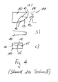
- Fig. 4a) to 4c show again in a schematic manner how it can come to the formation of the steps 7 in adjacent annular segments 1, 2.
- Fig. 4a is a plan view of a shroud 10 is shown with a Z-shaped end edge 13, wherein a working electrode 11 for processing the shroud 10 according to the direction of movement, which is characterized by the movement arrow 12, slides over the shroud 10.
- This does not have to be a mere parallel movement of the electrode 11 along the shroud 10 or the surface to be processed, but in principle a movement component, that is to say a movement part vector corresponding to the movement direction 12, is sufficient Fig.
- peripheral edge 13 is not perpendicular to the direction of movement 12 results in the front view, ie in a view according to the direction of movement 12, an image showing that in the area of the tips 15, a large material removal has taken place, while in the recessed areas 16 a lower Material removal has taken place, so that a height profile of the peripheral edge 13 results. Since the processing takes place in the same manner in the case of an adjacent blade rim segment, the contact areas are formed in the same way Fig. 1 shown stages that are undesirable.
- the invention now proposes to correct the height profile at the peripheral edge or adapt it to an adjacent blade rim segment such that a wave-shaped height profile is set on at least one annular space boundary surface of a blade ring segment.
- a wave-shaped height profile is set on at least one annular space boundary surface of a blade ring segment.
- the pressure-side annular space limiting surface 6 of the blade ring segment 2 is wave-shaped, while the adjacent annular space limiting surface 5 on the suction side of the blade ring segment 1 is further smooth.
- the waveform of the annular space limiting surface 6 is adapted to the peripheral edge, so that in the region of the protruding edge, ie in the region of projections 15, a mountain is formed in the height profile, while at recessed areas, ie in the region of the recesses 16, valleys in the topography of the wavy Height profile of the annular space boundary surface 6 is formed.
- the wave-shaped height profile of the annular space limiting surface 6 continues in accordance with the linear movement of the electrode and has, for example, in the present embodiment, an extension in the circumferential direction of the blade ring.
- the amplitude of the wave-shaped height profile depends on the radius of the blade ring, the number of blade ring segments, the shape angle or the draft of the shroud and the Z-shape of the end portion of the shroud.
- the magnitude of the amplitude of a corresponding undulating height profile is in the range of 0.2 mm to 1 mm, preferably 0.4 mm to 0.8 mm or 0.5 mm to 0.6 mm with a blade rim diameter in the range of 400 mm to 450 mm and a number of blade rim segments in the range of 75 to 80.
Landscapes
- Engineering & Computer Science (AREA)
- Mechanical Engineering (AREA)
- General Engineering & Computer Science (AREA)
- Physics & Mathematics (AREA)
- Chemical & Material Sciences (AREA)
- Fluid Mechanics (AREA)
- Electrochemistry (AREA)
- Chemical Kinetics & Catalysis (AREA)
- Thermal Sciences (AREA)
- Materials Engineering (AREA)
- Metallurgy (AREA)
- Organic Chemistry (AREA)
- Electrical Discharge Machining, Electrochemical Machining, And Combined Machining (AREA)
Abstract
Description
- Die vorliegende Erfindung betrifft ein Verfahren zur Bearbeitung eines Werkstücks, bei dem eine Elektrode im Abstand zu dem zu bearbeitenden Werkstück angeordnet wird und in Richtung des zu bearbeitenden Werkstücks linear verfahren wird, um zu bewirken, dass während der Annäherung an das Werkstück Material vom Werkstück abgetragen wird, wobei zumindest ein Ende oder ein Abschnitt eines Endes einer zu bearbeitenden Fläche des Werkstücks schräg zu einer Führungskante der diese Fläche bearbeitenden Elektrode verläuft und die Elektrode zumindest zum Teil mit der Elektrodenfläche parallel zur zu bearbeitenden Fläche bewegt wird, so dass bei der Annäherung an das Werkstück unterschiedlich stark bearbeitete Bereiche des Werkstücks mit einer ungleichmäßigen Randkante entstehen, außerdem betrifft die vorliegende Erfindung Schaufelkranzsegmente für einen Schaufelkranz einer Strömungsmaschine sowie einen entsprechenden Schaufelkranz, wobei die Schaufelkranzsegmente mit dem oben genannten Verfahren hergestellt werden.
- Für Strömungsmaschinen, wie beispielsweise Gasturbinen oder Flugtriebwerke können Schaufelkränze verwendet werden, bei denen eine Vielzahl von Schaufelkranzsegmente mit jeweils mindestens einem Schaufelblatt und einem inneren und/oder äußerem Deckband zu einem Schaufelkranz zusammengesetzt werden. Die Schaufelprofile der einzelnen Schaufelkranzsegmente definieren zwischen sich einen Ringraum durch den das Arbeitsgas strömt, wobei der Ringraum durch die Deckbänder begrenzt wird und die Deckbänder entsprechende Ringraumbegrenzungsflächen aufweisen.
- Derartige Schaufelkranzsegmente werden nach dem Stand der Technik durch Gießen oder Schmieden hergestellt, wobei insbesondere bei neueren, leichten Werkstoffen, wie z.B. TiAl-Werkstoffen, ein Schmieden zur Festigkeitssteigerung erforderlich ist. Entsprechend hergestellte Schaufelkranzsegmente müssen zur Erzielung der gewünschten Oberflächenform mechanisch nachbearbeitet werden, wobei beispielsweise elektrochemische Bearbeitungsverfahren zum Einsatz kommen, bei denen mit Hilfe von Arbeitselektroden und geeigneten Elektrolyten ein elektrochemischer Abtrag von Material von der zu bearbeitenden Werkstückfläche erzielt wird.
- Bei der elektrochemischen Bearbeitung wird die Arbeitselektrode in einer linearen Bewegung an die zu bearbeitende Oberfläche des Werkstücks angenähert, sodass durch das eingestellt Potential zwischen der Arbeitselektrode und der zu bearbeitenden Werkstückfläche ein entsprechender Materialabtrag stattfindet. Durch die lineare Bewegung der Elektrode in Richtung der zu bearbeitenden Werkstückoberfläche bei der Bearbeitung kommt es je nach Abstand von der zu bearbeitenden Oberfläche und der Bearbeitungsdauer zu einem unterschiedlich starken Materialabtrag. Entsprechend kann es durch einen vorgegebenen Bewegungspfad der Elektrode und der Geometrie des Schaufelkranzsegmentes zur Ausbildung eines Höhenprofils entlang der Endkante von Deckbändern des Schaufelkranzsegments kommen, insbesondere bei Z-förmig ausgebildeten Endbereichen von Außendeckbändern, die zur formschlüssigen Verbindung von benachbarten Schaufelkranzsegmenten Verwendung finden, wenn die Endkante des Deckbandes unterschiedlich lange mit unterschiedlichem Abstand gegenüber der Elektrode angeordnet ist. Durch das elektrochemische Bearbeiten des Deckbandes während die Elektrode über das Z-förmige Ende des Deckbands bewegt wird, kommt es somit zu einem unterschiedlich starken Materialabtrag entlang der Z-förmigen Randkante, sodass bei benachbarten Schaufelkranzsegmenten Stufen zwischen den Ringraumbegrenzungsflächen auftreten, was zu einer negativen Beeinflussung der Strömungsverhältnisse im Ringraum führt.
- Es ist deshalb Aufgabe der vorliegenden Erfindung ein Verfahren zur Bearbeitung eines Werkstücks bereitzustellen, bei dem entsprechende Probleme, wie sie im Stand der Technik gegeben sind, vermieden werden, wobei dieses Verfahren insbesondere zur Bearbeitung von Schaufelkranzsegmenten für Schaufelkränze von Strömungsmaschinen eingesetzt werden soll. Darüber hinaus sollen Schaufelkranzsegmente bzw. Schaufelkränze bereitgestellt werden, bei denen das Problem von Stufen zwischen benachbarten Ringraumbegrenzungsflächen an Deckbändern vermieden wird.
- Diese Aufgabe wird gelöst durch ein Verfahren mit den Merkmalen des Anspruchs 1 sowie ein Schaufelkranzsegment mit den Merkmalen des Anspruchs 6 und einen Schaufelkranz mit den Merkmalen des Anspruchs 10. Vorteilhafte Ausgestaltungen sind Gegenstand der abhängigen Ansprüche.
- Die Erfindung geht aus von der Erkenntnis, dass bei der Bearbeitung eines Werkstücks, wie beispielsweise eines Schaufelkranzsegments, mit mindestens einer Elektrode, die im Abstand zu dem zu bearbeitenden Werkstück angeordnet wird und bei der Bearbeitung in Richtung des zu bearbeitenden Werkstücks linear verfahren wird, einem unterschiedlichen Materialabtrag und einer entsprechenden Ausbildung einer bezüglich des Höhenprofils ungleichmäßigen Randkante dadurch begegnet werden kann, dass im Bereich der unterschiedlich starken Bearbeitung der Randkante die zu bearbeitende Fläche entsprechend dem Verlauf der Randkante mit einem entsprechend gegengerichteten Höhenprofil ausgebildet wird. Bewegt sich nämlich die Elektrode zumindest mit einem Anteil ihrer Bewegung, also mit einem Teilvektor des Bewegungsvektors parallel zur zu bearbeitenden Fläche des Werkstücks und ist ein Abschnitt des Endes der zu bearbeitenden Fläche des Werkstücks schräg zu einer in Bewegungsrichtung der Elektrode führenden Führungskante der bearbeitenden Elektrode ausgerichtet, so kommt es zu dem Fall, dass die Elektrode bestimmte Bereiche der zu bearbeitenden Werkstückfläche früher erreicht und länger oder mit geringerem Abstand bearbeitet als andere Bereiche, sodass ein unterschiedlich starker Materialabtrag stattfindet. Durch das Vorsehen eines Höhenprofils für die zu bearbeitende Fläche kann dies ausgeglichen werden, sodass die Randkante bezüglich des Höhenprofils korrigiert wird.
- Entsprechend kann in Bereichen, die früher bzw. länger in Wechselwirkung mit der Elektrode stehen ein erhöhtes Profil und somit ein geringerer Materialabtrag vorgesehen werden, während in Bereichen, die kürzer oder später mit der Elektrode in Wechselwirkung stehen, ein stärkerer Materialabtrag bzw. ein entsprechendes Tal oder abgesenktes Höhenprofil.
- Das Verfahren kann für alle Verfahren eingesetzt werden, bei denen Elektroden in entsprechender Weise bezüglich einer zu bearbeitender Werkstückfläche bewegt werden, wie beispielsweise das elektrochemische Bearbeiten ECM (electro chemical machining), das Erodieren, das Funkenerodieren, EDM (electro discharge machining) oder das elektrochemische Funkenerodieren ECDM (electro chemical discharge machining).
- Insbesondere kann das erfindungsgemäße Verfahren bei der Bearbeitung von Schaufelkranzsegmenten eines Schaufelkranzes mit äußerem und/oder innerem Deckband eingesetzt werden, um die Randkanten der Deckbänder benachbarter Schaufelkranzsegmente aneinander anzupassen.
- Das Verfahren kann somit zur gegenseitigen Anpassung der Z-förmigen Randkanten benachbarter Deckbänder von Schaufelkranzsegementen eingesetzt werden, wobei entsprechend dem Z-Profil eines Endes eines Deckbands eine wellenförmige Topographie bzw. ein wellenförmiges Höhenprofil an der Ringraumbegrenzungsfläche des Deckbands vorgesehen werden kann.
- Bei einer Bewegungsrichtung der Elektrode quer zum Ende des Deckbands mit dem Z-förmigen Profil kann das wellenförmige Höhenprofil der Ringraumbegrenzungsfläche so ausgebildet sein, dass an den Vorsprüngen des Z-Profils Berge vorgesehen sind und an den zurückgesetzten Bereichen des Z-Profils Täler. Diese Berge und Täler des wellenförmigen Höhenprofils können sich gemäß der Bearbeitungsrichtung mit der die Elektrode bezüglich der Ringraumbegrenzungsfläche bewegt wird, fortsetzen, und zwar beispielsweise in Umfangsrichtung des Schaufelkranzes, für den das Schaufelkranzsegment vorgesehen ist, wenn die Bewegungsrichtung der Elektrode in dieser Richtung erfolgt.
- Das wellige Höhenprofil kann insbesondere an der druckseitigen Ringraumbegrenzungsfläche vorgesehen sein, da die Einflüsse der Wellenform auf die Strömungsverhältnisse dort geringere Auswirkungen aufweisen.
- Ein entsprechender Schaufelkranz mit Schaufelkranzsegmenten, die wellenförmige Ringraumbegrenzungsflächen aufweisen kann so aufgebaut sein, dass abwechselnd gerade, ebene Ringraumbegrenzungsflächen an wellenförmige Ringraumbegrenzungsflächen angrenzen, wobei die wellenförmigen Ringraumbegrenzungsflächen eine Anpassung der Randkante an das benachbarte Schaufelkranzsegment aufweisen. Folglich können abwechselnd Schaufelkranzsegmente mit jeweils einer wellenförmigen Ringraumbegrenzungsfläche und einer glatten, ebenen Ringraumbegrenzungsfläche angeordnet werden. In gleicher Weise ist es vorstellbar jeweils abwechselnd Schaufelkranzsegmente vorzusehen, die zwei wellenförmige Ringraumbegrenzungsflächen aufweisen, während das benachbarte Schaufelkranzsegment keine wellenförmige Ringraumbegrenzungsfläche aufweist, sondern lediglich glatte, ebene Ringraumbegrenzungsflächen besitzt. Unter glatter, ebener Ringraumbegrenzungsfläche wird eine Fläche verstanden, die keine wellenförmige Anpassung der Oberflächentopographie gemäß der vorliegenden Erfindung aufweist.
- Die unterschiedlichen Anordnungen der Schaufelkranzsegmente kann auch entsprechend miteinander kombiniert werden, sodass beispielsweise zunächst Schaufelkranzsegmente mit jeweils einer wellenförmigen Ringraumbegrenzungsfläche nebeneinander angeordnet werden und dann übergegangen wird zu einer abwechselnden Anordnung von Schaufelkranzsegmenten mit entweder zwei wellenförmigen Ringraumbegrenzungsflächen oder keiner wellenförmigen Ringraumbegrenzungsfläche.
- Die beigefügten Zeichnungen zeigen in rein schematischer Weise in
-
Fig. 1 einen Teil eines Schaufelkranzes einer Strömungsmaschine mit benachbarten Schaufelkranzsegmenten nach dem Stand der Technik in perspektivischer Darstellung; -
Fig. 2 eine Draufsicht auf ein Schaufelkranzsegment; -
Fig. 3 eine teilweise Schnittdarstellung des Schaufelkranzsegments ausFig. 2 gemäß der Schnittlinie B-B; -
Fig. 4 eine Darstellung der ECM-Bearbeitung eines Deckbands mit Z- förmiger Endkante, wobei die Teilansicht a) eine Draufsicht, die Teilansicht b) eine Seitenansicht und die Teilansicht c) eine Frontansicht zeigen; und in -
Fig. 5 eine perspektivische Darstellung ähnlich der Darstellung derFig. 1 mit einer erfindungsgemäßen wellenförmigen Ringraumbe- grenzungsfläche. - Weitere Vorteile, Kennzeichen und Merkmale der vorliegenden Erfindung werden bei der nachfolgenden detaillierten Beschreibung eines Ausführungsbeispiels deutlich werden. Allerdings ist die Erfindung nicht auf dieses Ausführungsbeispiel beschränkt.
- Die
Fig. 1 zeigt einen Teil eines Schaufelkranzes mit zwei benachbarten Schaufelkranzsegmenten 1 und 2, wie sie bei Strömungsmaschinen, wie beispielsweise Gasturbinen oder Flugtriebwerken, eingesetzt werden. Die benachbarten Schaufelkranzsegmente 1 und 2 weisen in dem gezeigten Ausführungsbeispiel zwei Deckbänder mit Ringraumbegrenzungsflächen 5,6 auf, die an ihren Endkanten in einer Z-Form komplementär zueinander ausgebildet sind, sodass die Schaufelkranzsegmente 1 und 2 miteinander formschlüssig verbunden sind. Üblicherweise wird diese Z-Profilform an den Außendeckbändern vorgesehen, wobei zur besseren Darstellung dieFig. 1 um 180° Grad gedreht ist, sodass das äußere Deckband unten dargestellt ist. - Die Schaufelkranzsegmente 1 und 2 weisen jeweils ein Schaufelprofil 3 und 4 auf, welche bezüglich der Umfangsrichtung des Schaufelkranzes schräg bzw. quer und/oder gekrümmt angeordnet sind.
- Die
Fig. 2 und 3 zeigen eine Draufsicht (Fig. 2 ) auf ein Schaufelkranzsegment 1 sowie eine Schnittdarstellung (Fig. 3 ) entlang der Schnittlinie B-B ausFig. 2 . - Bei der Herstellung von entsprechenden Schaufelkranzsegmenten müssen diese formgebend endbearbeitet werden, insbesondere wenn die Schaufelkranzsegmente schmiedetechnisch hergestellt worden sind, um den Schaufelkranzsegmenten durch das Schmieden die erforderliche Festigkeit zu verleihen. Dies ist beispielsweise bei Schaufelkranzsegmenten, die aus leichten TiAI-Werkstoffen herstellt werden sollen, der Fall. Als mögliche Bearbeitung der Schaufelkranzsegmente und insbesondere der Schaufelprofilflächen und der Deckbandflächen 5 und 6, die den sogenannten Profilraum zwischen den Schaufelprofilen 3, 4 begrenzen, kommen elektrochemische Bearbeitungsverfahren in Frage. Bei der sogenannten elektrochemischen Bearbeitung (electro chemical machining ECM) werden eine oder mehrere Formelektroden in der Nähe der zu bearbeitenden Werkstückflächen angeordnet und bis zu einem definierten Abstand in Richtung der Werkstückoberfläche verfahren, sodass durch ein angelegtes Potential zwischen der Elektrode und der Werkstückoberfläche bei Anwesenheit eines geeigneten Elektrolyten ein Materialabtrag an der zu bearbeitenden Werkstückoberfläche erfolgt. Hierbei kommt es bezüglich des Materialabtrags auf die Bearbeitungsdauer und den Abstand der Elektrode von der zu bearbeitenden Werkstückoberfläche an.
- Die
Fig. 3 zeigt beispielsweise mit den Pfeilen 8 die Bewegungsrichtung bzw. Zustellrichtung der Elektroden für die Bearbeitung der Profilflächen des Schaufelprofils 3 und der Ringraumbegrenzungsfläche 5 des Schaufelkranzsegments 1. Die Bewegung der Elektrode bei der ECM-Bearbeitung erfolgt linear. Hierbei kann es bei bestimmter Anordnung der zu bearbeitenden Werkstückfläche zu der Arbeitselektrode während der Annäherung zu einem unterschiedlich großen Materialabtrag in verschiedenen Bereiche der Werkstückfläche kommen. Dies führt beispielsweise an den Enden der Deckbänder mit Z-Profil dazu, dass die Randkanten der Ringraumbegrenzungsflächen 5, 6 ein unterschiedliches Höhenprofil aufweisen. Bei benachbarten Schaufelkranzsegmenten 1 und 2 können somit Stufen 7 an den Kontaktbereichen der benachbarten Schaufelkranzsegmente 1, 2 vorliegen, die unerwünscht sind, da sie die Strömungsverhältnisse im Ringraum ungünstig beeinflussen können. - Die
Fig. 4a) bis 4c ) zeigen noch einmal in einer schematischen Art und Weise, wie es zur Ausbildung der Stufen 7 bei benachbarten Ringkranzsegmenten 1, 2 kommen kann. InFig. 4a ) ist eine Draufsicht auf ein Deckband 10 mit einer Z-förmigen Endkante 13 gezeigt, wobei eine Arbeitselektrode 11 zur Bearbeitung des Deckbands 10 sich entsprechend der Bewegungsrichtung, die durch den Bewegungspfeil 12 gekennzeichnet ist, über das Deckband 10 schiebt. Hierbei muss es sich nicht um eine reine parallele Bewegung der Elektrode 11 entlang des Deckbands 10 bzw. der zu bearbeitenden Fläche handeln, sondern es genügt im Prinzip ein Bewegungsanteil, also ein Bewegungsteilvektor entsprechend der Bewegungsrichtung 12. Aus derFig. 4a ) wird deutlich, dass die Elektrode 11 mit ihrer Führungskante 14 bei der Z-förmigen Endkante 13 zunächst die hervorstehenden Spitzen 15 des Z-Profils erreicht, sodass dort eine Bearbeitung bzw. ein Materialabtrag beginnt. Mit zusätzlicher Bewegung in Richtung der Bewegungsrichtung 12 schreitet die Bearbeitung fort, sodass auch die Randkante 13 im Bereich der Einbuchtungen bzw. Aussparungen 16 erreicht wird und dort die Bearbeitung bzw. der Materialabtrag beginnt. Allerdings ergibt sich durch die Bewegung der Elektrode 11 in der Bewegungsrichtung 12 ein keilförmiger Abtrag, wie er im Teilbild b) derFig. 4 dargestellt ist. Da die Randkante 13 nicht senkrecht zur Bewegungsrichtung 12 verläuft ergibt sich in der Frontansicht, also in einer Sicht gemäß der Bewegungsrichtung 12 ein Bild, das zeigt, dass im Bereich der Spitzen 15 ein großer Materialabtrag stattgefunden hat, während im Bereich der zurückversetzten Bereiche 16 ein geringerer Materialabtrag stattgefunden hat, sodass sich ein Höhenprofil der Randkante 13 ergibt. Da bei einem benachbarten Schaufelkranzsegment die Bearbeitung in der gleichen Weise erfolgt, ergeben sich an den Kontaktbereichen die inFig. 1 gezeigten Stufen, die unerwünscht sind. - Die Erfindung schlägt nun vor das Höhenprofil an der Randkante dadurch zu korrigieren bzw. an ein benachbartes Schaufelkranzsegment anzupassen, dass ein wellenförmiges Höhenprofil an mindestens einer Ringraumbegrenzungsfläche eines Schaufelkranzsegments eingestellt wird. Dies ist in der
Fig. 5 gezeigt. Bei der gezeigten Ausführungsform ist die druckseitige Ringraumbegrenzungsfläche 6 des Schaufelkranzsegments 2 wellenförmig ausgebildet, während die benachbarte Ringraumbegrenzungsfläche 5 auf der Saugseite des Schaufelkranzsegments 1 weiterhin glatt ausgebildet ist. Die Wellenform der Ringraumbegrenzungsfläche 6 ist an die Randkante angepasst, sodass im Bereich der vorstehenden Randkante, also im Bereich von Vorsprüngen 15, ein Berg im Höhenprofil ausgebildet ist, während an zurückgesetzten Bereichen, also im Bereich der Ausnehmungen 16, Täler in der Topographie des wellenförmigen Höhenprofils der Ringraumbegrenzungsfläche 6 ausgebildet ist. Das wellenförmige Höhenprofil der Ringraumbegrenzungsfläche 6 setzt sich entsprechend der linearen Bewegung der Elektrode fort und weist beispielsweise bei der vorliegenden Ausführungsform eine Erstreckung in Umfangsrichtung des Schaufelkranzes auf. - Die Amplitude des wellenförmigen Höhenprofils hängt ab von dem Radius des Schaufelkranzes, von der Anzahl der Schaufelkranzsegmente, von dem Formwinkel bzw. der Formschräge des Deckbands und der Z-Form des Endbereichs des Deckbands. Je kleiner beispielsweise der Radius des Schaufelkranzes ist oder je kleiner die Anzahl der Schaufelkranzsegmente ist, desto stärker ist das wellenförmige Höhenprofil auszubilden. Die Größenordnung der Amplitude eines entsprechenden wellenförmigen Höhenprofils liegt im Bereich von 0,2 mm bis 1 mm vorzugsweise 0,4 mm bis 0,8 mm oder 0,5 mm bis 0,6 mm bei einem Schaufelkranzdurchmesser im Bereich von 400 mm bis 450 mm und einer Anzahl an Schaufelkranzsegmenten im Bereich von 75 bis 80.
- Obwohl die vorliegende Erfindung anhand des Ausführungsbeispiels detailliert beschrieben worden ist, ist für den Fachmann selbstverständlich, dass die Erfindung nicht auf dieses Ausführungsbeispiel beschränkt ist. Vielmehr sind Abwandlungen in der Weise möglich, dass einzelne Merkmale weggelassen werden oder andersartige Kombinationen von Merkmalen vorgenommen werden, ohne das der Schutzbereich der beigefügten Ansprüche verlassen wird. Die vorliegende Offenbarung umfasst insbesondere sämtliche Kombinationen aller vorgestellter Einzelmerkmale.
Claims (11)
- Verfahren zur Bearbeitung eines Werkstücks, bei dem eine Elektrode im Abstand zu einem zu bearbeitenden Werkstück angeordnet wird und in Richtung des zu bearbeitenden Werkstücks linear verfahren wird, um zu bewirken, dass während der Annäherung an das Werkstück Material vom Werkstück abgetragen wird, wobei zumindest ein Ende oder ein Abschnitt eines Endes einer zu bearbeitenden Fläche des Werkstücks schräg zu einer Führungskante (14) der diese Fläche bearbeitenden Elektrode verläuft und die Elektrode zumindest zum Teil mit der Elektrodenfläche parallel zur zu bearbeitenden Fläche (10) bewegt wird, so dass bei der Annäherung an das Werkstück unterschiedlich stark bearbeitete Bereiche des Werkstücks mit einer ungleichmäßigen Randkante (13) entstehen,
dadurch gekennzeichnet, dass
die unterschiedlich starke Bearbeitung an der Randkante der zu bearbeitenden Fläche dadurch kompensiert wird, dass die zu bearbeitende Fläche mit einem dem Verlauf des Endes der zu bearbeitenden Fläche angepassten Höhenprofil versehen wird. - Verfahren nach Anspruch 1,
dadurch gekennzeichnet, dass
das Höhenprofil in Bereichen (15), in denen das Ende der zu bearbeitende Fläche in entgegengesetzter Richtung zu dem zur Fläche parallelen Bewegungsrichtungsanteil hervorsteht und von der Führungskante (14) der Elektrode zuerst überschritten wird, ein geringerer Materialabtrag und somit ein erhöhtes Profil vorgesehen wird, als in Bereichen (16), in denen das Ende der zu bearbeitenden Fläche in Richtung zu dem zur Fläche parallelen Bewegungsrichtungsanteil zurückgezogen ist und von der Führungskante der Elektrode später überschritten wird und somit ein abgesenktes Profil vorgesehen wird. - Verfahren nach Anspruch 1 oder 2,
dadurch gekennzeichnet, dass
dass das Verfahren den elektrochemischen Materialabtrag (ECM), das Erodieren, das Funkenerodieren (EDM (electro discharge machining)) oder das elektrochemische Funkenerodiern (ECDM (elctrochemical discharge machining)) verwendet. - Verfahren nach einem der vorhergehenden Ansprüche,
dadurch gekennzeichnet, dass
es bei der Bearbeitung von Schaufelkranzsegmenten (1,2) eines Schaufelkranzes mit äußerem und/oder innerem Deckband eingesetzt wird, um die Randkanten benachbarter Schaufelkranzsegmente aneinander anzupassen. - Verfahren nach einem der vorhergehenden Ansprüche,
dadurch gekennzeichnet, dass
die Elektrode zumindest mit einem Bewegungsanteil quer zu einer Z-förmigen Kante des Deckbands in Umfangsrichtung des Schaufelkranzes bewegt wird, so dass das Deckband ein Höhenprofil mit in Umfangsrichtung verlaufenden Bergen und/oder Tälern erhält, wobei die Berge im Bereich der in Umfangsrichtung hervorstehenden Abschnitte des Endes des Deckbandes und die Täler in Bereichen der in Umfangsrichtung zurückgezogenen Abschnitte des Endes des Deckbands vorgesehen werden. - Schaufelkranzsegment für einen Schaufelkranz einer Strömungsmaschine mit einem äußeren und/oder inneren Deckband, wobei das Deckband mit seiner radial zum Schaufelprofil gewandten Seite einen Ringraum begrenzt und mindestens eine, vorzugsweise jeweils eine Ringraumbegrenzungsfläche (5,6) an einer Druckseite und einer Saugseite eines Schaufelprofils des Schaufelkranzsegments definiert,
dadurch gekennzeichnet, dass
zumindest eine Ringraumbegrenzungsfläche mit einem welligen Höhenprofil ausgebildet ist. - Schaufelkranzsegment nach Anspruch 6,
dadurch gekennzeichnet, dass
das wellige Höhenprofil von einer Z-förmigen Endkante (13) des Deckbands ausgeht, wobei das wellige Höhenprofil im Bereich der Vorsprünge der Z-förmigen Endkante Berge und im Bereich der Einbuchtungen der Z-förmigen Endkante Täler aufweist und sich die Täler und Berge in Umfangsrichtung des Schaufelkranzes erstrecken. - Schaufelkranzsegment nach Anspruch 6 oder 7,
dadurch gekennzeichnet, dass
das wellige Höhenprofil an der druckseitigen Ringraumbegrenzungsfläche (5) und/oder am Außendeckband ausgebildet ist. - Schaufelkranzsegment nach einem der Ansprüche 6 bis 8,
dadurch gekennzeichnet, dass
das Schaufelkranzsegment hinterschnittfrei ausgebildet ist und/oder geschmiedet ist. - Schaufelkranz für eine Strömungsmaschine mit einer Vielzahl von Schaufelkranzsegmenten,
dadurch gekennzeichnet, dass
die Schaufelkranzsegmente mehrere Schaufelkranzsegmente (1,2) nach einem der Ansprüche 6 bis 7 umfassen, die so im Schaufelkranz angeordnet sind, dass die Deckbänder an den Kontaktstellen keinen Höhenversatz aufweisen. - Schaufelkranz nach Anspruch 8,
dadurch gekennzeichnet, dass
die Schaufelkranzsegmente (1,2) im Schaufelkranz abwechselnd mit jeweils einem welligen Ringraum und einem ebenen Ringraum angeordnet sind, wobei welliger und ebener Ringraum jeweils aneinander grenzen, oder dass abwechselnd Schaufelkranzsegmente ohne wellige Ringräume und Schaufelkranzsegmente mit zwei welligen Ringräumen angeordnet sind, oder dass Kombinationen aus den unterschiedlichen Anordnungen vorgesehen sind.
Priority Applications (4)
| Application Number | Priority Date | Filing Date | Title |
|---|---|---|---|
| ES12159601.9T ES2581753T3 (es) | 2012-03-15 | 2012-03-15 | Segmento de corona de álabes con superficie de delimitación de espacio anular con un perfil de altura ondulado así como procedimiento para fabricar el mismo |
| EP12159601.9A EP2639004B1 (de) | 2012-03-15 | 2012-03-15 | Schaufelkranzsegment mit Ringraumbegrenzungsfläche mit einem welligen Höhenprofil sowie Verfahren zur Herstellung desselben |
| US13/804,217 US9500082B2 (en) | 2012-03-15 | 2013-03-14 | Blade ring segment having an annular space delimiting surface having a wavy height profile |
| US15/299,005 US20170036284A1 (en) | 2012-03-15 | 2016-10-20 | Method for machining a workpiece having an irregular edge |
Applications Claiming Priority (1)
| Application Number | Priority Date | Filing Date | Title |
|---|---|---|---|
| EP12159601.9A EP2639004B1 (de) | 2012-03-15 | 2012-03-15 | Schaufelkranzsegment mit Ringraumbegrenzungsfläche mit einem welligen Höhenprofil sowie Verfahren zur Herstellung desselben |
Publications (2)
| Publication Number | Publication Date |
|---|---|
| EP2639004A1 true EP2639004A1 (de) | 2013-09-18 |
| EP2639004B1 EP2639004B1 (de) | 2016-05-11 |
Family
ID=45841336
Family Applications (1)
| Application Number | Title | Priority Date | Filing Date |
|---|---|---|---|
| EP12159601.9A Not-in-force EP2639004B1 (de) | 2012-03-15 | 2012-03-15 | Schaufelkranzsegment mit Ringraumbegrenzungsfläche mit einem welligen Höhenprofil sowie Verfahren zur Herstellung desselben |
Country Status (3)
| Country | Link |
|---|---|
| US (2) | US9500082B2 (de) |
| EP (1) | EP2639004B1 (de) |
| ES (1) | ES2581753T3 (de) |
Families Citing this family (2)
| Publication number | Priority date | Publication date | Assignee | Title |
|---|---|---|---|---|
| FR2993927B1 (fr) * | 2012-07-27 | 2014-08-22 | Snecma | Piece de modification du profil d'une veine aerodynamique |
| US12294999B2 (en) * | 2020-02-13 | 2025-05-06 | Lenovo (Beijing) Ltd. | Method and apparatus for beam-based transmission for sidelink |
Citations (4)
| Publication number | Priority date | Publication date | Assignee | Title |
|---|---|---|---|---|
| DE1816216A1 (de) * | 1967-12-21 | 1969-10-16 | Production Engineering Res Ass | Verfahren und Vorrichtung zur elektrochemischen Maschinenbearbeitung |
| US5149405A (en) * | 1991-05-28 | 1992-09-22 | Lehr Precision Inc. | Four-axis ECM machine and method of operation |
| EP1559871A2 (de) * | 2004-01-31 | 2005-08-03 | United Technologies Corporation | Laufschaufel für eine Turbomaschine |
| US20090211921A1 (en) * | 2008-02-27 | 2009-08-27 | Mtu Aero Engines Gmbh | Procedure for the production and application of a protective layer |
Family Cites Families (8)
| Publication number | Priority date | Publication date | Assignee | Title |
|---|---|---|---|---|
| US3723268A (en) | 1967-12-21 | 1973-03-27 | Prod Eng Res Ass | Electrochemical machining |
| US6561761B1 (en) * | 2000-02-18 | 2003-05-13 | General Electric Company | Fluted compressor flowpath |
| US6786698B2 (en) * | 2002-12-19 | 2004-09-07 | General Electric Company | Steam turbine bucket flowpath |
| FR2864990B1 (fr) * | 2004-01-14 | 2008-02-22 | Snecma Moteurs | Perfectionnements apportes aux fentes d'evacuation de l'air de refroidissement d'aubes de turbine haute-pression |
| US7220100B2 (en) * | 2005-04-14 | 2007-05-22 | General Electric Company | Crescentic ramp turbine stage |
| DE102008038038A1 (de) * | 2008-08-16 | 2010-02-18 | Mtu Aero Engines Gmbh | Laufschaufelsystem für eine Laufschaufelreihe einer Strömungsmaschine |
| EP2261462A1 (de) * | 2009-06-02 | 2010-12-15 | Alstom Technology Ltd | Turbinenstufenendwand |
| US8439643B2 (en) * | 2009-08-20 | 2013-05-14 | General Electric Company | Biformal platform turbine blade |
-
2012
- 2012-03-15 EP EP12159601.9A patent/EP2639004B1/de not_active Not-in-force
- 2012-03-15 ES ES12159601.9T patent/ES2581753T3/es active Active
-
2013
- 2013-03-14 US US13/804,217 patent/US9500082B2/en not_active Expired - Fee Related
-
2016
- 2016-10-20 US US15/299,005 patent/US20170036284A1/en not_active Abandoned
Patent Citations (4)
| Publication number | Priority date | Publication date | Assignee | Title |
|---|---|---|---|---|
| DE1816216A1 (de) * | 1967-12-21 | 1969-10-16 | Production Engineering Res Ass | Verfahren und Vorrichtung zur elektrochemischen Maschinenbearbeitung |
| US5149405A (en) * | 1991-05-28 | 1992-09-22 | Lehr Precision Inc. | Four-axis ECM machine and method of operation |
| EP1559871A2 (de) * | 2004-01-31 | 2005-08-03 | United Technologies Corporation | Laufschaufel für eine Turbomaschine |
| US20090211921A1 (en) * | 2008-02-27 | 2009-08-27 | Mtu Aero Engines Gmbh | Procedure for the production and application of a protective layer |
Also Published As
| Publication number | Publication date |
|---|---|
| US9500082B2 (en) | 2016-11-22 |
| EP2639004B1 (de) | 2016-05-11 |
| US20130243602A1 (en) | 2013-09-19 |
| US20170036284A1 (en) | 2017-02-09 |
| ES2581753T3 (es) | 2016-09-07 |
Similar Documents
| Publication | Publication Date | Title |
|---|---|---|
| EP3473431B1 (de) | Schaufel und rotor für eine strömungsmaschine sowie strömungsmaschine | |
| DE102008019332A1 (de) | Verfahren zum Fräsen von Blisks | |
| EP2158381B1 (de) | Leitschaufel für eine gasturbine | |
| DE102007002326A1 (de) | Turbinenschaufel- und Leitkranzkonstruktion | |
| DE102012010756A1 (de) | Verfahren zur Herstellung eines Ölabstreifkolbenrings | |
| EP2921714A1 (de) | Schaufelreihengruppe | |
| EP3404210A1 (de) | Schaufelgittersegment für eine strömungsmaschine mit achsen-asymmetrischer plattformoberfläche, zugehörige schaufelgitter, schaufelkanal, plattform, und strömungsmaschine | |
| EP2806992B1 (de) | Mehrteilige elektrodenanordnung und verfahren zur elektrochemischen bearbeitung von schaufeln mit deckbändern | |
| EP2625445A1 (de) | Verfahren zur herstellung eines kolbenrings | |
| EP2410131B1 (de) | Rotor einer Turbomaschine | |
| DE102012104240B4 (de) | Hybridströmungs-Schaufeldesigns | |
| EP3401504B1 (de) | Schaufelgitter | |
| DE102011102598A1 (de) | Verfahren zur Herstellung einer Wabendichtung, Wabendichtung sowie Strömungsmaschine | |
| EP3388626B1 (de) | Konturierung einer schaufelgitterplattform | |
| EP3228827A1 (de) | Dichtungsträger für eine turbomaschine, zugehörige gasturbine und herstellungsverfahren | |
| WO2007115533A1 (de) | Verfahren zur reparatur eines leitschaufelsegments | |
| DE102014226689A1 (de) | Rotor-Schaufelblatt einer Axialströmungsmaschine | |
| EP2639004B1 (de) | Schaufelkranzsegment mit Ringraumbegrenzungsfläche mit einem welligen Höhenprofil sowie Verfahren zur Herstellung desselben | |
| EP3228826B1 (de) | Dichtungssegmentanordnung mit steckverbindung, zugehörige gasturbine und herstellungsverfahren | |
| DE102013224199A1 (de) | Gasturbinen-Laufschaufel | |
| DE102019219403A1 (de) | Rotor für eine Strömungsmaschine und Strömungsmaschine | |
| WO2015074787A1 (de) | Ein dichtungsring einer dampfturbinen welche zwischen zwei gehäusehälften in ringnuten positioniert ist | |
| EP3015652A1 (de) | Laufschaufel für eine Turbine | |
| EP3514333A1 (de) | Rotorschaufeldeckband für eine strömungsmaschine, rotorschaufel, verfahren zum herstellen eines rotorschaufeldeckbands und einer rotorschaufel | |
| EP3428391A1 (de) | Turbomaschinen-schaufelgitter |
Legal Events
| Date | Code | Title | Description |
|---|---|---|---|
| PUAI | Public reference made under article 153(3) epc to a published international application that has entered the european phase |
Free format text: ORIGINAL CODE: 0009012 |
|
| AK | Designated contracting states |
Kind code of ref document: A1 Designated state(s): AL AT BE BG CH CY CZ DE DK EE ES FI FR GB GR HR HU IE IS IT LI LT LU LV MC MK MT NL NO PL PT RO RS SE SI SK SM TR |
|
| AX | Request for extension of the european patent |
Extension state: BA ME |
|
| RAP1 | Party data changed (applicant data changed or rights of an application transferred) |
Owner name: MTU AERO ENGINES AG |
|
| 17P | Request for examination filed |
Effective date: 20140318 |
|
| RBV | Designated contracting states (corrected) |
Designated state(s): AL AT BE BG CH CY CZ DE DK EE ES FI FR GB GR HR HU IE IS IT LI LT LU LV MC MK MT NL NO PL PT RO RS SE SI SK SM TR |
|
| GRAP | Despatch of communication of intention to grant a patent |
Free format text: ORIGINAL CODE: EPIDOSNIGR1 |
|
| INTG | Intention to grant announced |
Effective date: 20151014 |
|
| GRAS | Grant fee paid |
Free format text: ORIGINAL CODE: EPIDOSNIGR3 |
|
| GRAA | (expected) grant |
Free format text: ORIGINAL CODE: 0009210 |
|
| AK | Designated contracting states |
Kind code of ref document: B1 Designated state(s): AL AT BE BG CH CY CZ DE DK EE ES FI FR GB GR HR HU IE IS IT LI LT LU LV MC MK MT NL NO PL PT RO RS SE SI SK SM TR |
|
| REG | Reference to a national code |
Ref country code: GB Ref legal event code: FG4D Free format text: NOT ENGLISH |
|
| REG | Reference to a national code |
Ref country code: CH Ref legal event code: EP |
|
| REG | Reference to a national code |
Ref country code: AT Ref legal event code: REF Ref document number: 798252 Country of ref document: AT Kind code of ref document: T Effective date: 20160515 |
|
| REG | Reference to a national code |
Ref country code: IE Ref legal event code: FG4D Free format text: LANGUAGE OF EP DOCUMENT: GERMAN |
|
| REG | Reference to a national code |
Ref country code: DE Ref legal event code: R096 Ref document number: 502012007047 Country of ref document: DE |
|
| REG | Reference to a national code |
Ref country code: ES Ref legal event code: FG2A Ref document number: 2581753 Country of ref document: ES Kind code of ref document: T3 Effective date: 20160907 |
|
| REG | Reference to a national code |
Ref country code: LT Ref legal event code: MG4D |
|
| REG | Reference to a national code |
Ref country code: NL Ref legal event code: MP Effective date: 20160511 |
|
| PG25 | Lapsed in a contracting state [announced via postgrant information from national office to epo] |
Ref country code: NO Free format text: LAPSE BECAUSE OF FAILURE TO SUBMIT A TRANSLATION OF THE DESCRIPTION OR TO PAY THE FEE WITHIN THE PRESCRIBED TIME-LIMIT Effective date: 20160811 Ref country code: NL Free format text: LAPSE BECAUSE OF FAILURE TO SUBMIT A TRANSLATION OF THE DESCRIPTION OR TO PAY THE FEE WITHIN THE PRESCRIBED TIME-LIMIT Effective date: 20160511 Ref country code: FI Free format text: LAPSE BECAUSE OF FAILURE TO SUBMIT A TRANSLATION OF THE DESCRIPTION OR TO PAY THE FEE WITHIN THE PRESCRIBED TIME-LIMIT Effective date: 20160511 Ref country code: LT Free format text: LAPSE BECAUSE OF FAILURE TO SUBMIT A TRANSLATION OF THE DESCRIPTION OR TO PAY THE FEE WITHIN THE PRESCRIBED TIME-LIMIT Effective date: 20160511 |
|
| PG25 | Lapsed in a contracting state [announced via postgrant information from national office to epo] |
Ref country code: SE Free format text: LAPSE BECAUSE OF FAILURE TO SUBMIT A TRANSLATION OF THE DESCRIPTION OR TO PAY THE FEE WITHIN THE PRESCRIBED TIME-LIMIT Effective date: 20160511 Ref country code: LV Free format text: LAPSE BECAUSE OF FAILURE TO SUBMIT A TRANSLATION OF THE DESCRIPTION OR TO PAY THE FEE WITHIN THE PRESCRIBED TIME-LIMIT Effective date: 20160511 Ref country code: PT Free format text: LAPSE BECAUSE OF FAILURE TO SUBMIT A TRANSLATION OF THE DESCRIPTION OR TO PAY THE FEE WITHIN THE PRESCRIBED TIME-LIMIT Effective date: 20160912 Ref country code: HR Free format text: LAPSE BECAUSE OF FAILURE TO SUBMIT A TRANSLATION OF THE DESCRIPTION OR TO PAY THE FEE WITHIN THE PRESCRIBED TIME-LIMIT Effective date: 20160511 Ref country code: GR Free format text: LAPSE BECAUSE OF FAILURE TO SUBMIT A TRANSLATION OF THE DESCRIPTION OR TO PAY THE FEE WITHIN THE PRESCRIBED TIME-LIMIT Effective date: 20160812 Ref country code: RS Free format text: LAPSE BECAUSE OF FAILURE TO SUBMIT A TRANSLATION OF THE DESCRIPTION OR TO PAY THE FEE WITHIN THE PRESCRIBED TIME-LIMIT Effective date: 20160511 |
|
| PG25 | Lapsed in a contracting state [announced via postgrant information from national office to epo] |
Ref country code: IT Free format text: LAPSE BECAUSE OF FAILURE TO SUBMIT A TRANSLATION OF THE DESCRIPTION OR TO PAY THE FEE WITHIN THE PRESCRIBED TIME-LIMIT Effective date: 20160511 |
|
| PG25 | Lapsed in a contracting state [announced via postgrant information from national office to epo] |
Ref country code: RO Free format text: LAPSE BECAUSE OF FAILURE TO SUBMIT A TRANSLATION OF THE DESCRIPTION OR TO PAY THE FEE WITHIN THE PRESCRIBED TIME-LIMIT Effective date: 20160511 Ref country code: DK Free format text: LAPSE BECAUSE OF FAILURE TO SUBMIT A TRANSLATION OF THE DESCRIPTION OR TO PAY THE FEE WITHIN THE PRESCRIBED TIME-LIMIT Effective date: 20160511 Ref country code: SK Free format text: LAPSE BECAUSE OF FAILURE TO SUBMIT A TRANSLATION OF THE DESCRIPTION OR TO PAY THE FEE WITHIN THE PRESCRIBED TIME-LIMIT Effective date: 20160511 Ref country code: CZ Free format text: LAPSE BECAUSE OF FAILURE TO SUBMIT A TRANSLATION OF THE DESCRIPTION OR TO PAY THE FEE WITHIN THE PRESCRIBED TIME-LIMIT Effective date: 20160511 Ref country code: EE Free format text: LAPSE BECAUSE OF FAILURE TO SUBMIT A TRANSLATION OF THE DESCRIPTION OR TO PAY THE FEE WITHIN THE PRESCRIBED TIME-LIMIT Effective date: 20160511 |
|
| REG | Reference to a national code |
Ref country code: DE Ref legal event code: R097 Ref document number: 502012007047 Country of ref document: DE |
|
| PG25 | Lapsed in a contracting state [announced via postgrant information from national office to epo] |
Ref country code: PL Free format text: LAPSE BECAUSE OF FAILURE TO SUBMIT A TRANSLATION OF THE DESCRIPTION OR TO PAY THE FEE WITHIN THE PRESCRIBED TIME-LIMIT Effective date: 20160511 Ref country code: SM Free format text: LAPSE BECAUSE OF FAILURE TO SUBMIT A TRANSLATION OF THE DESCRIPTION OR TO PAY THE FEE WITHIN THE PRESCRIBED TIME-LIMIT Effective date: 20160511 |
|
| PLBE | No opposition filed within time limit |
Free format text: ORIGINAL CODE: 0009261 |
|
| STAA | Information on the status of an ep patent application or granted ep patent |
Free format text: STATUS: NO OPPOSITION FILED WITHIN TIME LIMIT |
|
| REG | Reference to a national code |
Ref country code: FR Ref legal event code: PLFP Year of fee payment: 6 |
|
| 26N | No opposition filed |
Effective date: 20170214 |
|
| PG25 | Lapsed in a contracting state [announced via postgrant information from national office to epo] |
Ref country code: SI Free format text: LAPSE BECAUSE OF FAILURE TO SUBMIT A TRANSLATION OF THE DESCRIPTION OR TO PAY THE FEE WITHIN THE PRESCRIBED TIME-LIMIT Effective date: 20160511 |
|
| REG | Reference to a national code |
Ref country code: CH Ref legal event code: PL |
|
| PG25 | Lapsed in a contracting state [announced via postgrant information from national office to epo] |
Ref country code: MC Free format text: LAPSE BECAUSE OF FAILURE TO SUBMIT A TRANSLATION OF THE DESCRIPTION OR TO PAY THE FEE WITHIN THE PRESCRIBED TIME-LIMIT Effective date: 20160511 |
|
| REG | Reference to a national code |
Ref country code: IE Ref legal event code: MM4A |
|
| PG25 | Lapsed in a contracting state [announced via postgrant information from national office to epo] |
Ref country code: LU Free format text: LAPSE BECAUSE OF NON-PAYMENT OF DUE FEES Effective date: 20170315 |
|
| PG25 | Lapsed in a contracting state [announced via postgrant information from national office to epo] |
Ref country code: LI Free format text: LAPSE BECAUSE OF NON-PAYMENT OF DUE FEES Effective date: 20170331 Ref country code: IE Free format text: LAPSE BECAUSE OF NON-PAYMENT OF DUE FEES Effective date: 20170315 Ref country code: CH Free format text: LAPSE BECAUSE OF NON-PAYMENT OF DUE FEES Effective date: 20170331 |
|
| REG | Reference to a national code |
Ref country code: BE Ref legal event code: MM Effective date: 20170331 |
|
| REG | Reference to a national code |
Ref country code: FR Ref legal event code: PLFP Year of fee payment: 7 |
|
| REG | Reference to a national code |
Ref country code: AT Ref legal event code: MM01 Ref document number: 798252 Country of ref document: AT Kind code of ref document: T Effective date: 20170315 |
|
| PG25 | Lapsed in a contracting state [announced via postgrant information from national office to epo] |
Ref country code: BE Free format text: LAPSE BECAUSE OF NON-PAYMENT OF DUE FEES Effective date: 20170331 |
|
| PG25 | Lapsed in a contracting state [announced via postgrant information from national office to epo] |
Ref country code: AT Free format text: LAPSE BECAUSE OF NON-PAYMENT OF DUE FEES Effective date: 20170315 |
|
| PG25 | Lapsed in a contracting state [announced via postgrant information from national office to epo] |
Ref country code: MT Free format text: LAPSE BECAUSE OF FAILURE TO SUBMIT A TRANSLATION OF THE DESCRIPTION OR TO PAY THE FEE WITHIN THE PRESCRIBED TIME-LIMIT Effective date: 20160511 |
|
| PG25 | Lapsed in a contracting state [announced via postgrant information from national office to epo] |
Ref country code: AL Free format text: LAPSE BECAUSE OF FAILURE TO SUBMIT A TRANSLATION OF THE DESCRIPTION OR TO PAY THE FEE WITHIN THE PRESCRIBED TIME-LIMIT Effective date: 20160511 |
|
| PG25 | Lapsed in a contracting state [announced via postgrant information from national office to epo] |
Ref country code: HU Free format text: LAPSE BECAUSE OF FAILURE TO SUBMIT A TRANSLATION OF THE DESCRIPTION OR TO PAY THE FEE WITHIN THE PRESCRIBED TIME-LIMIT; INVALID AB INITIO Effective date: 20120315 |
|
| PG25 | Lapsed in a contracting state [announced via postgrant information from national office to epo] |
Ref country code: BG Free format text: LAPSE BECAUSE OF FAILURE TO SUBMIT A TRANSLATION OF THE DESCRIPTION OR TO PAY THE FEE WITHIN THE PRESCRIBED TIME-LIMIT Effective date: 20160511 |
|
| PG25 | Lapsed in a contracting state [announced via postgrant information from national office to epo] |
Ref country code: CY Free format text: LAPSE BECAUSE OF NON-PAYMENT OF DUE FEES Effective date: 20160511 |
|
| PG25 | Lapsed in a contracting state [announced via postgrant information from national office to epo] |
Ref country code: MK Free format text: LAPSE BECAUSE OF FAILURE TO SUBMIT A TRANSLATION OF THE DESCRIPTION OR TO PAY THE FEE WITHIN THE PRESCRIBED TIME-LIMIT Effective date: 20160511 |
|
| PG25 | Lapsed in a contracting state [announced via postgrant information from national office to epo] |
Ref country code: TR Free format text: LAPSE BECAUSE OF FAILURE TO SUBMIT A TRANSLATION OF THE DESCRIPTION OR TO PAY THE FEE WITHIN THE PRESCRIBED TIME-LIMIT Effective date: 20160511 |
|
| PGFP | Annual fee paid to national office [announced via postgrant information from national office to epo] |
Ref country code: GB Payment date: 20200325 Year of fee payment: 9 Ref country code: DE Payment date: 20200324 Year of fee payment: 9 |
|
| PGFP | Annual fee paid to national office [announced via postgrant information from national office to epo] |
Ref country code: FR Payment date: 20200325 Year of fee payment: 9 |
|
| PG25 | Lapsed in a contracting state [announced via postgrant information from national office to epo] |
Ref country code: IS Free format text: LAPSE BECAUSE OF FAILURE TO SUBMIT A TRANSLATION OF THE DESCRIPTION OR TO PAY THE FEE WITHIN THE PRESCRIBED TIME-LIMIT Effective date: 20160911 |
|
| PGFP | Annual fee paid to national office [announced via postgrant information from national office to epo] |
Ref country code: ES Payment date: 20200421 Year of fee payment: 9 |
|
| REG | Reference to a national code |
Ref country code: DE Ref legal event code: R119 Ref document number: 502012007047 Country of ref document: DE |
|
| GBPC | Gb: european patent ceased through non-payment of renewal fee |
Effective date: 20210315 |
|
| PG25 | Lapsed in a contracting state [announced via postgrant information from national office to epo] |
Ref country code: DE Free format text: LAPSE BECAUSE OF NON-PAYMENT OF DUE FEES Effective date: 20211001 Ref country code: GB Free format text: LAPSE BECAUSE OF NON-PAYMENT OF DUE FEES Effective date: 20210315 Ref country code: FR Free format text: LAPSE BECAUSE OF NON-PAYMENT OF DUE FEES Effective date: 20210331 |
|
| REG | Reference to a national code |
Ref country code: ES Ref legal event code: FD2A Effective date: 20220523 |
|
| PG25 | Lapsed in a contracting state [announced via postgrant information from national office to epo] |
Ref country code: ES Free format text: LAPSE BECAUSE OF NON-PAYMENT OF DUE FEES Effective date: 20210316 |