EP2637956B1 - Elevator safety circuit - Google Patents
Elevator safety circuit Download PDFInfo
- Publication number
- EP2637956B1 EP2637956B1 EP11774031.6A EP11774031A EP2637956B1 EP 2637956 B1 EP2637956 B1 EP 2637956B1 EP 11774031 A EP11774031 A EP 11774031A EP 2637956 B1 EP2637956 B1 EP 2637956B1
- Authority
- EP
- European Patent Office
- Prior art keywords
- safety
- relay
- elevator
- drive
- circuit
- Prior art date
- Legal status (The legal status is an assumption and is not a legal conclusion. Google has not performed a legal analysis and makes no representation as to the accuracy of the status listed.)
- Active
Links
- 239000003990 capacitor Substances 0.000 claims description 10
- 238000000034 method Methods 0.000 claims description 5
- 238000012544 monitoring process Methods 0.000 claims description 2
- 239000008186 active pharmaceutical agent Substances 0.000 description 7
- 230000003111 delayed effect Effects 0.000 description 5
- 229910000831 Steel Inorganic materials 0.000 description 3
- 230000001351 cycling effect Effects 0.000 description 3
- 230000011664 signaling Effects 0.000 description 3
- 239000010959 steel Substances 0.000 description 3
- 102100029054 Homeobox protein notochord Human genes 0.000 description 1
- 101000634521 Homo sapiens Homeobox protein notochord Proteins 0.000 description 1
- 208000027418 Wounds and injury Diseases 0.000 description 1
- 239000004760 aramid Substances 0.000 description 1
- 229920003235 aromatic polyamide Polymers 0.000 description 1
- 230000006378 damage Effects 0.000 description 1
- 230000005484 gravity Effects 0.000 description 1
- 231100001261 hazardous Toxicity 0.000 description 1
- 230000000977 initiatory effect Effects 0.000 description 1
- 208000014674 injury Diseases 0.000 description 1
- 238000009434 installation Methods 0.000 description 1
- 230000007257 malfunction Effects 0.000 description 1
- 229920002994 synthetic fiber Polymers 0.000 description 1
Images


Classifications
-
- B—PERFORMING OPERATIONS; TRANSPORTING
- B66—HOISTING; LIFTING; HAULING
- B66B—ELEVATORS; ESCALATORS OR MOVING WALKWAYS
- B66B1/00—Control systems of elevators in general
- B66B1/24—Control systems with regulation, i.e. with retroactive action, for influencing travelling speed, acceleration, or deceleration
- B66B1/28—Control systems with regulation, i.e. with retroactive action, for influencing travelling speed, acceleration, or deceleration electrical
- B66B1/32—Control systems with regulation, i.e. with retroactive action, for influencing travelling speed, acceleration, or deceleration electrical effective on braking devices, e.g. acting on electrically controlled brakes
-
- B—PERFORMING OPERATIONS; TRANSPORTING
- B66—HOISTING; LIFTING; HAULING
- B66B—ELEVATORS; ESCALATORS OR MOVING WALKWAYS
- B66B13/00—Doors, gates, or other apparatus controlling access to, or exit from, cages or lift well landings
- B66B13/22—Operation of door or gate contacts
-
- B—PERFORMING OPERATIONS; TRANSPORTING
- B66—HOISTING; LIFTING; HAULING
- B66B—ELEVATORS; ESCALATORS OR MOVING WALKWAYS
- B66B5/00—Applications of checking, fault-correcting, or safety devices in elevators
- B66B5/02—Applications of checking, fault-correcting, or safety devices in elevators responsive to abnormal operating conditions
Definitions
- an elevator car and a counterweight are conventionally supported on and interconnected by traction means.
- the traction means is driven through engagement with a motor-driven traction sheave to move the car and counterweight in opposing directions along the elevator hoistway.
- the drive unit consisting of the motor, an associated brake and the traction sheave, is normally located in the upper end of the elevator hoistway or alternatively in a machine room directly above the hoistway.
- Safety of the elevator is monitored and governed by means of a safety circuit or chain containing numerous contacts or sensors.
- a safety circuit or chain containing numerous contacts or sensors.
- a safety relay within the safety circuit transmits a signal to an elevator control which instructs the drive to perform an emergency stop by immediately de-energizing the motor and applying the brake.
- the elevator cannot be called back into normal operation until the reason for the break in the safety circuit has been investigated and the relevant safety contact/sensor reset.
- a similar circuit is described in EP-A1-1864935 but instead of signalling an emergency stop through the control, a drive relay and a brake relay are connected in series to the safety chain so that if one of the safety contacts opens the drive relay and brake relay immediately open to de-energise the drive and release the brake, respectively.
- US 3,584,706 discloses that during normal operations of stopping an elevator, the triggering of a switch can be delayed in the operating sequence to permit gradual stopping of the elevator car. However, during an emergency stop, the triggering of the switch is immediate. Similarly, US 4,359,208 proposes delaying the braking of an elevator if it is being raised as the force of gravity will eventually bring it to a stop.
- an objective of the present invention is to provide an alternative elevator safety circuit which can be used to decelerate an elevator car during an emergency stop in a more controlled manner.
- an elevator safety circuit comprising a series chain of safety contacts having an input connected to a power source and a first safety relay deriving electrical power from an output of the series chain of safety contacts.
- a delay circuit is arranged between the output of the series chain of safety contacts and the first safety relay.
- the delay circuit may comprise a diode and a resistor arranged between the output of the series chain of safety contacts and the first safety relay and can further comprise a capacitor in parallel across the resistor and the first safety relay. Accordingly, the amount of delay can be set by selecting an appropriate R-C constant for the delay circuit.
- the elevator safety circuit further comprises a watchdog timer arranged to selectively bypass the first safety relay. Consequently, the first safety relay can be operated immediately and independently by the watchdog timer without a break in the series chain of safety contacts.
- the watchdog timer can be arranged in parallel with the first safety relay. Alternatively, the watchdog timer may be arranged in parallel with the capacitor.
- the elevator safety circuit can further comprise a second safety relay arranged in parallel with the delay circuit and the first safety relay. Hence, if any of the safety contacts open to initiate an emergency stop, any process controlled by the operation of the second safety relay is immediate.
- the second safety relay may be arranged between the output of the series chain of safety contacts and the delay circuit.
- a second diode can be arranged between the output terminal of the series chain of safety contacts and the watchdog timer to ensure that both the first and the second safety relays can be operated immediately by the watchdog timer.
- the delay circuit and the first safety relay may be integrated together as a time-delay relay.
- the time-delay relay can be a normally-open, timed-open relay or a normally-closed, timed-open relay.
- the first safety relay is a brake contact such that if an emergency stop is initiated, the brake is not applied immediately but after a delay.
- the brake contact is a time-delay relay, then a second watchdog timer can be arranged in the brake circuit to selectively bypass the coils of the brakes.
- the second safety relay is a drive relay such that if an emergency stop is initiated, the drive relay immediately informs the elevator drive to either actively control the motor to decelerate the elevator or de-energise the motor.
- the invention also provides a method for controlling the motion of an elevator comprising the steps of detecting whether a safety contact opens and operating a first safety relay a predetermined time interval after the opening of the safety contact.
- the method further comprises the steps of monitoring a drive of the elevator and operating the first safety relay when the drive experiences a software problem, a hardware problem or if the power supply to the drive is outside of permitted tolerances. Accordingly, the first safety relay can be operated independently of the safety contacts.
- a first elevator safety circuit 1 is shown in FIG. 1 wherein an electrical power supply PS is connected to an input terminal T1 of a series chain of safety contacts S1-Sn.
- the contacts S1-Sn monitor various conditions of the elevator and remain closed in normal operation.
- contact S1 could be a landing door contact which will remain closed so long as that particular landing door is closed. If the landing door is opened without the concurrent attendance of the elevator car at that particular landing, indicating a possibly hazardous condition, the contact S1 will open and thereby break the safety chain 1 initiating an emergency stop which will be discussed in more detail below.
- a drive relay 3 is connected between the output terminal T2 of the series chain of safety contacts S1-Sn and a common reference point 0V.
- the common reference point is hereinafter referred to a gound and is considered to have zero voltage.
- the delay circuit 13 comprises a diode D1, a resistor R and a capacitor C.
- the diode D1 and the resistor R are arranged in series between the output terminal T2 and an input terminal T4 to the brake contactor 7 whereby the diode D1 is biased to permit current flow in that particular direction and the capacitor C is arranged between ground 0V and the junction T3 of the first diode D1 and the resistor R.
- the drive relay 3 immediately opens signalling to the drive 7 that an emergency stop is required whereupon the drive 7 actively controls the motor 11 to immediately decelerate the elevator.
- the drive relay 3 can be arranged to de-energise the motor 11.
- the invention provides a two phase emergency stop sequence comprising a first phase wherein the drive 5 immediately controls the motor 11 to decelerate the elevator in a controlled manner and a subsequent second phase wherein the brakes 9 are applied.
- the elevator safety circuit 1 also contains a watchdog timer 15 connected in parallel across the brake contactor 7 i.e. between the terminal T4 and ground 0V.
- the watchdog timer 15 could be connected in parallel across the capacitor C of the delay circuit 13 as illustrated in the embodiment of FIG. 2 .
- the watchdog timer 15 receives a signal DS from the drive 5. Under normal operating conditions, this signal DS is continuously sequenced on and off as depicted in FIG. 3 and the watchdog timer 15 remains open.
- the signal DS from the drive 5 stops cycling and after a short time period ⁇ t1 the watchdog timer 15 times out and closes. Should this happen, the safety circuit 1 discharges through the watchdog timer 15 so that the drive relay 3 and the brake contactor 7 immediately open as in the prior art.
- FIG. 2 An alternative elevator safety circuit 1' according to the invention is illustrated in FIG. 2 .
- the circuit 1' essentially contains the same components as in the previous embodiment but in this case the drive relay 3 and the brake contactor 7 are arranged in series between the output terminal T2 of the series chain of safety contacts S1-Sn and ground 0V.
- the circuit 1' provides a two phase emergency stop sequence comprising a first phase wherein the drive 5 immediately controls the motor 11 to decelerate the elevator in a controlled manner and a subsequent second phase wherein the brakes 9 are applied.
- the watchdog timer 15 it is not sufficient for the watchdog timer 15 to bypass just the brake contactor 7 as in the previous embodiment, since power would still flow through the drive relay 3 if there is a malfunction with the drive 5. Instead, a second diode D2 is inserted between the output terminal T2 and the watchdog timer 15 to drain the circuit 1' and ensure that both the drive relay 3 and the brake contact 7 are opened immediately if there is a drive fault.
- FIG. 4 A further embodiment of the invention is shown on FIG. 4 .
- this circuit 1" the delay circuit 13 and brake contactor 7 of FIG. 1 are replaced by a time-delay relay 17.
- the relay 17 is a normally-open, timed-open relay NOTO as depicted in FIG. 5 having the switching characteristics illustrated in FIG. 6 .
- the circuit 1" is interrupted and current no longer flows through the coils of drive relay 3 or the time-delay relay 17. Accordingly, the drive relay 3 immediately opens signalling to the drive 7 that an emergency stop is required whereupon the drive 7 actively controls the motor 11 to immediately decelerate the elevator.
- the time-delay relay 17 remains closed for a predetermined time period ⁇ t2 after its coil has been de-energised and accordingly the time-delay relay 17 will continue to close the brake circuit and the brakes 9 will remain open or de-active during the predetermined time period ⁇ ft2.
- this embodiment provides a two phase emergency stop sequence comprising a first phase wherein the drive 5 immediately controls the motor 11 to decelerate the elevator in a controlled manner and a subsequent second phase wherein the brakes 9 are applied.
- the elevator safety circuit 1"' contains a first watchdog timer 15 connected in parallel across the time-delay relay 17.
- the first watchdog timer 15 receives a signal DS from the drive 5. Under normal operating conditions, this signal DS is continuously sequenced on and off as depicted in FIG. 3 and the first watchdog timer 15 remains open. If the drive 5 experiences a software or hardware problem or if the power supply to the drive 5 is outside of permitted tolerances, as in the case of a power disruption, the signal DS from the drive 5 stops cycling and after a short time period ⁇ t1 the first watchdog timer 15 times out and closes.
- the safety circuit 1"' discharges through the first watchdog timer 15 so that the drive relay 3 immediately opens.
- the time-delay relay 17 will not open immediately but will instead be delayed for a certain time period ⁇ ft2.
- a second watchdog timer 15' is installed in the brake circuit 19 to permit current to bypass the coils of the brakes 9 if the signal DS from the drive 5 stops cycling. Accordingly, both the drive 5 and the brakes 9 are notified simultaneously if there is a drive fault by the first and the second watchdog timers, respectively.
- the present invention is has been developed, in particular, for use in conjunction with synthetic traction means, it can equally be applied to any elevator to reduce the deceleration of an elevator car during an emergency stop and thereby improve passenger comfort.
Landscapes
- Engineering & Computer Science (AREA)
- Automation & Control Theory (AREA)
- Elevator Control (AREA)
- Maintenance And Inspection Apparatuses For Elevators (AREA)
Description
- In an elevator installation, an elevator car and a counterweight are conventionally supported on and interconnected by traction means. The traction means is driven through engagement with a motor-driven traction sheave to move the car and counterweight in opposing directions along the elevator hoistway. The drive unit, consisting of the motor, an associated brake and the traction sheave, is normally located in the upper end of the elevator hoistway or alternatively in a machine room directly above the hoistway.
- Safety of the elevator is monitored and governed by means of a safety circuit or chain containing numerous contacts or sensors. Such a system is disclosed in
US 6,446,760 . Should one of the safety contacts open or one of the safety sensors indicate an unsafe condition during normal operation of the elevator, a safety relay within the safety circuit transmits a signal to an elevator control which instructs the drive to perform an emergency stop by immediately de-energizing the motor and applying the brake. The elevator cannot be called back into normal operation until the reason for the break in the safety circuit has been investigated and the relevant safety contact/sensor reset. A similar circuit is described inEP-A1-1864935 but instead of signalling an emergency stop through the control, a drive relay and a brake relay are connected in series to the safety chain so that if one of the safety contacts opens the drive relay and brake relay immediately open to de-energise the drive and release the brake, respectively. -
US 3,584,706 discloses that during normal operations of stopping an elevator, the triggering of a switch can be delayed in the operating sequence to permit gradual stopping of the elevator car. However, during an emergency stop, the triggering of the switch is immediate. Similarly,US 4,359,208 proposes delaying the braking of an elevator if it is being raised as the force of gravity will eventually bring it to a stop. - Traditionally, steel cables have been used as traction means. More recently, synthetic cables and belt-like traction means comprising steel or aramid cords of relatively small diameter coated in a synthetic material have been developed. An important aspect of these synthetic traction means is the significant increase in the coefficient of friction they exhibit through engagement with the traction sheave as compared to the traditional steel cables. Due to this increase in relative coefficient of friction, when the brake is applied in an emergency stop for an elevator employing synthetic traction means there is an significant increase in the deceleration of the car which severely degrades passenger comfort and could even result in injury to passengers.
- Accordingly, an objective of the present invention is to provide an alternative elevator safety circuit which can be used to decelerate an elevator car during an emergency stop in a more controlled manner. This objective is achieved by an elevator safety circuit comprising a series chain of safety contacts having an input connected to a power source and a first safety relay deriving electrical power from an output of the series chain of safety contacts. A delay circuit is arranged between the output of the series chain of safety contacts and the first safety relay. Hence, if any of the safety contacts open to initiate an emergency stop, any process controlled by the operation of the first safety relay is delayed.
- The delay circuit may comprise a diode and a resistor arranged between the output of the series chain of safety contacts and the first safety relay and can further comprise a capacitor in parallel across the resistor and the first safety relay. Accordingly, the amount of delay can be set by selecting an appropriate R-C constant for the delay circuit.
- The elevator safety circuit further comprises a watchdog timer arranged to selectively bypass the first safety relay. Consequently, the first safety relay can be operated immediately and independently by the watchdog timer without a break in the series chain of safety contacts. The watchdog timer can be arranged in parallel with the first safety relay. Alternatively, the watchdog timer may be arranged in parallel with the capacitor.
- The elevator safety circuit can further comprise a second safety relay arranged in parallel with the delay circuit and the first safety relay. Hence, if any of the safety contacts open to initiate an emergency stop, any process controlled by the operation of the second safety relay is immediate.
- Alternatively, the second safety relay may be arranged between the output of the series chain of safety contacts and the delay circuit. With this series arrangement, a second diode can be arranged between the output terminal of the series chain of safety contacts and the watchdog timer to ensure that both the first and the second safety relays can be operated immediately by the watchdog timer.
- The delay circuit and the first safety relay may be integrated together as a time-delay relay. The time-delay relay can be a normally-open, timed-open relay or a normally-closed, timed-open relay.
- Preferably, the first safety relay is a brake contact such that if an emergency stop is initiated, the brake is not applied immediately but after a delay. If the brake contact is a time-delay relay, then a second watchdog timer can be arranged in the brake circuit to selectively bypass the coils of the brakes.
- Preferably, the second safety relay is a drive relay such that if an emergency stop is initiated, the drive relay immediately informs the elevator drive to either actively control the motor to decelerate the elevator or de-energise the motor.
- The invention also provides a method for controlling the motion of an elevator comprising the steps of detecting whether a safety contact opens and operating a first safety relay a predetermined time interval after the opening of the safety contact.
- The method further comprises the steps of monitoring a drive of the elevator and operating the first safety relay when the drive experiences a software problem, a hardware problem or if the power supply to the drive is outside of permitted tolerances. Accordingly, the first safety relay can be operated independently of the safety contacts.
- The invention is herein described by way of specific examples with reference to the accompanying drawings of which:
-
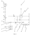
FIG. 1 is a schematic of an elevator safety circuit according to a first embodiment of the present invention; -
FIG. 2 is a schematic of an elevator safety circuit according to a second embodiment of the present invention: -
FIG. 3 depicts graphical representations of the control signal to, and the associated response of, the watchdog relay employed in the circuits shown inFIGS. 1 and2 : -
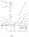
FIG. 4 is a schematic of an elevator safety circuit according to a third embodiment of the present invention: -
FIG. 5 illustrates a typical time-delay relay for use in the circuit ofFIG. 4 ; and -
FIG. 6 depicts graphical representations of the coil power to, and the associated response of, the time-delay relay ofFIG. 5 . - A first
elevator safety circuit 1 according to the invention is shown inFIG. 1 wherein an electrical power supply PS is connected to an input terminal T1 of a series chain of safety contacts S1-Sn. The contacts S1-Sn monitor various conditions of the elevator and remain closed in normal operation. For example, contact S1 could be a landing door contact which will remain closed so long as that particular landing door is closed. If the landing door is opened without the concurrent attendance of the elevator car at that particular landing, indicating a possibly hazardous condition, the contact S1 will open and thereby break thesafety chain 1 initiating an emergency stop which will be discussed in more detail below. - A
drive relay 3 is connected between the output terminal T2 of the series chain of safety contacts S1-Sn and a common reference point 0V. The common reference point is hereinafter referred to a gound and is considered to have zero voltage. - Power is also supplied by the output terminal T2 through a
delay circuit 13 to abrake contactor 7. Thedelay circuit 13 comprises a diode D1, a resistor R and a capacitor C. The diode D1 and the resistor R are arranged in series between the output terminal T2 and an input terminal T4 to thebrake contactor 7 whereby the diode D1 is biased to permit current flow in that particular direction and the capacitor C is arranged between ground 0V and the junction T3 of the first diode D1 and the resistor R. - Accordingly, in normal operation, with all safety contacts S1-Sn closed on the series chain, current flows from the power supply PS through the series chain S1-Sn and through the respective coils of the
drive relay 3 and thebrake contactor 7 maintaining both in their closed positions. Furthermore, the current flow will also charge the capacitor C of thedelay circuit 13. With thedrive relay 3 in its closed position theelevator drive 5 continues to control themotor 11 to raise and lower an elevator car in accordance with passenger requests received by the elevator controller. Similarly, with thebrake contactor 7 closed, current flows through thebrake circuit 19 to electromagnetically hold theelevator brakes 9 open against the biasing force of conventional brake springs. - If, however, an emergency situation is detected and one of the safety contacts S1-Sn opens, the
circuit 1 is interrupted and current no longer flows through the coil ofdrive relay 3. Accordingly, thedrive relay 3 immediately opens signalling to thedrive 7 that an emergency stop is required whereupon thedrive 7 actively controls themotor 11 to immediately decelerate the elevator. Alternatively, thedrive relay 3 can be arranged to de-energise themotor 11. - Meanwhile, although no current flows through the diode D1, the charged capacitor C of the
delay circuit 13 will discharge through the resistor R to maintain current flow through the coil of thebrake contactor 7. Accordingly, thebrake contactor 7 will continue to close thebrake circuit 19 and thebrakes 9 will remain open or de-active until the capacitor C has discharged sufficiently. Hence, although thesafety circuit 1 has been interrupted, thebrakes 9 will not be applied immediately but will instead be delayed for a certain time period determined by the R-C constant employed in thedelay circuit 13. Hence, the invention provides a two phase emergency stop sequence comprising a first phase wherein thedrive 5 immediately controls themotor 11 to decelerate the elevator in a controlled manner and a subsequent second phase wherein thebrakes 9 are applied. - The
elevator safety circuit 1 also contains awatchdog timer 15 connected in parallel across thebrake contactor 7 i.e. between the terminal T4 and ground 0V. Alternatively, thewatchdog timer 15 could be connected in parallel across the capacitor C of thedelay circuit 13 as illustrated in the embodiment ofFIG. 2 . Thewatchdog timer 15 receives a signal DS from thedrive 5. Under normal operating conditions, this signal DS is continuously sequenced on and off as depicted inFIG. 3 and thewatchdog timer 15 remains open. If thedrive 5 experiences a software or hardware problem or if the power supply to thedrive 5 is outside of permitted tolerances, as in the case of a power disruption, the signal DS from thedrive 5 stops cycling and after a short time period Δt1 thewatchdog timer 15 times out and closes. Should this happen, thesafety circuit 1 discharges through thewatchdog timer 15 so that thedrive relay 3 and thebrake contactor 7 immediately open as in the prior art. - An alternative elevator safety circuit 1' according to the invention is illustrated in
FIG. 2 . The circuit 1' essentially contains the same components as in the previous embodiment but in this case thedrive relay 3 and thebrake contactor 7 are arranged in series between the output terminal T2 of the series chain of safety contacts S1-Sn and ground 0V. Again, the circuit 1' provides a two phase emergency stop sequence comprising a first phase wherein thedrive 5 immediately controls themotor 11 to decelerate the elevator in a controlled manner and a subsequent second phase wherein thebrakes 9 are applied. - In the present embodiment, it is not sufficient for the
watchdog timer 15 to bypass just thebrake contactor 7 as in the previous embodiment, since power would still flow through thedrive relay 3 if there is a malfunction with thedrive 5. Instead, a second diode D2 is inserted between the output terminal T2 and thewatchdog timer 15 to drain the circuit 1' and ensure that both thedrive relay 3 and thebrake contact 7 are opened immediately if there is a drive fault. - A further embodiment of the invention is shown on
FIG. 4 . In thiscircuit 1" thedelay circuit 13 andbrake contactor 7 ofFIG. 1 are replaced by a time-delay relay 17. In the present example therelay 17 is a normally-open, timed-open relay NOTO as depicted inFIG. 5 having the switching characteristics illustrated inFIG. 6 . - In normal operation, with all safety contacts S1-Sn closed on the series chain, current flows from the power supply PS through the series chain S1-Sn and through the respective coils of the
drive relay 3 and the time-delay relay 17 maintaining both in their closed positions. With the time-delay relay 17 closed, current flows through thebrake circuit 19 to electromagnetically hold theelevator brakes 9 open against the biasing force of conventional brake springs. - If an emergency situation is detected and one of the safety contacts S1-Sn opens, the
circuit 1" is interrupted and current no longer flows through the coils ofdrive relay 3 or the time-delay relay 17. Accordingly, thedrive relay 3 immediately opens signalling to thedrive 7 that an emergency stop is required whereupon thedrive 7 actively controls themotor 11 to immediately decelerate the elevator. On the other hand, as illustrated inFIG. 6 the time-delay relay 17 remains closed for a predetermined time period Δt2 after its coil has been de-energised and accordingly the time-delay relay 17 will continue to close the brake circuit and thebrakes 9 will remain open or de-active during the predetermined time period Δft2. Hence, although thecircuit 1" has been interrupted, thebrakes 9 will not be applied immediately but will instead be delayed for a certain time period Δt2. Again, this embodiment provides a two phase emergency stop sequence comprising a first phase wherein thedrive 5 immediately controls themotor 11 to decelerate the elevator in a controlled manner and a subsequent second phase wherein thebrakes 9 are applied. - As in this first embodiment shown in
FIG. 1 , theelevator safety circuit 1"' contains afirst watchdog timer 15 connected in parallel across the time-delay relay 17. As previously described, thefirst watchdog timer 15 receives a signal DS from thedrive 5. Under normal operating conditions, this signal DS is continuously sequenced on and off as depicted inFIG. 3 and thefirst watchdog timer 15 remains open. If thedrive 5 experiences a software or hardware problem or if the power supply to thedrive 5 is outside of permitted tolerances, as in the case of a power disruption, the signal DS from thedrive 5 stops cycling and after a short time period Δt1 thefirst watchdog timer 15 times out and closes. Should this happen, thesafety circuit 1"' discharges through thefirst watchdog timer 15 so that thedrive relay 3 immediately opens. However, in this embodiment, even though thesafety circuit 1"' discharges through thefirst watchdog timer 15, by its very nature, the time-delay relay 17 will not open immediately but will instead be delayed for a certain time period Δft2. To overcome this problem, a second watchdog timer 15' is installed in thebrake circuit 19 to permit current to bypass the coils of thebrakes 9 if the signal DS from thedrive 5 stops cycling. Accordingly, both thedrive 5 and thebrakes 9 are notified simultaneously if there is a drive fault by the first and the second watchdog timers, respectively. - The skilled person will readily appreciate that the invention as defined in the following claims is not limited to the examples described hereinbefore. For example, instead of mounting the brake sets 12,14 within the drive unit as depicted in
FIG.1 , they could be mounted on the car so as to frictionally engage the guide rails to bring the car to a halt. Furthermore, although the two safety relays have been specifically described as being operative with respect to the brake and the drive, they can just as easily be used to control other functions within the elevator. - Although the present invention is has been developed, in particular, for use in conjunction with synthetic traction means, it can equally be applied to any elevator to reduce the deceleration of an elevator car during an emergency stop and thereby improve passenger comfort.
Claims (11)
- An elevator safety circuit comprising:a series chain of safety contacts (S1-Sn) having an input (T1) connected to a power source (PS);a first safety relay (7) deriving electrical power from an output (T2) of the series chain of safety contacts (S1-Sn); anda delay circuit (13) arranged between the output (T2) of the series chain of safety contacts (S1-Sn) and the first safety relay (7)characterised infurther comprising a watchdog timer (15) arranged to selectively bypass the first safety relay (7).
- An elevator safety circuit according to claim 1, wherein the delay circuit (13) comprises:a diode (D1) and a resistor (R) arranged in series between the output (T2) of the series chain of safety contacts (S1-Sn) and the first safety relay (7); anda capacitor (C) in parallel across the resistor (R) and the first safety relay (7).
- An elevator safety circuit according to claim 1 or claim 2, wherein the watchdog timer (15) is arranged in parallel with the first safety relay (7).
- An elevator safety circuit according to claim 2, wherein the watchdog timer (15) is arranged in parallel with the capacitor (C).
- An elevator safety circuit according to any preceding claim, further comprising a second safety relay (3) arranged in parallel with the delay circuit (13) and the first safety relay (7).
- An elevator safety circuit according to any of claims 1 to 4, further comprising a second safety relay (3) arranged between the output (T2) of the series chain of safety contacts (S1-Sn) and the delay circuit (13).
- An elevator safety circuit according to claim 6, further comprising a second diode (D2) arranged between the output terminal (T2) of the series chain of safety contacts (S1-Sn) and the watchdog timer (15).
- An elevator safety circuit according to any preceding claim, wherein the delay circuit and the first safety relay are integrated together as a time-delay relay (17).
- An elevator safety circuit according to claim 8, wherein the time-delay relay is a normally-open, timed-open relay (NOTO).
- An elevator safety circuit according to claim 8, wherein the time-delay relay is a normally-closed, timed-open relay (NCTO).
- A method for controlling the motion of an elevator comprising the steps of:detecting whether a safety contact (S1-Sn) opens;operating a first safety relay (7) a predetermined time interval after the opening of the safety contact (S1-Sn);monitoring a drive (5) of the elevator; andoperating the first safety relay (7) when the drive (5) experiences a software problem, a hardware problem or if the power supply to the drive (5) is outside of permitted tolerances.
Priority Applications (1)
| Application Number | Priority Date | Filing Date | Title |
|---|---|---|---|
| EP11774031.6A EP2637956B1 (en) | 2010-11-11 | 2011-10-20 | Elevator safety circuit |
Applications Claiming Priority (3)
| Application Number | Priority Date | Filing Date | Title |
|---|---|---|---|
| EP10190927A EP2452907A1 (en) | 2010-11-11 | 2010-11-11 | Elevator Safety Circuit |
| EP11774031.6A EP2637956B1 (en) | 2010-11-11 | 2011-10-20 | Elevator safety circuit |
| PCT/EP2011/068370 WO2012062553A1 (en) | 2010-11-11 | 2011-10-20 | Elevator safety circuit |
Publications (2)
| Publication Number | Publication Date |
|---|---|
| EP2637956A1 EP2637956A1 (en) | 2013-09-18 |
| EP2637956B1 true EP2637956B1 (en) | 2016-04-13 |
Family
ID=43779687
Family Applications (2)
| Application Number | Title | Priority Date | Filing Date |
|---|---|---|---|
| EP10190927A Withdrawn EP2452907A1 (en) | 2010-11-11 | 2010-11-11 | Elevator Safety Circuit |
| EP11774031.6A Active EP2637956B1 (en) | 2010-11-11 | 2011-10-20 | Elevator safety circuit |
Family Applications Before (1)
| Application Number | Title | Priority Date | Filing Date |
|---|---|---|---|
| EP10190927A Withdrawn EP2452907A1 (en) | 2010-11-11 | 2010-11-11 | Elevator Safety Circuit |
Country Status (13)
| Country | Link |
|---|---|
| US (1) | US8997941B2 (en) |
| EP (2) | EP2452907A1 (en) |
| KR (1) | KR101925648B1 (en) |
| CN (1) | CN103201205B (en) |
| AU (1) | AU2011328440B2 (en) |
| BR (1) | BR112013010156B1 (en) |
| CA (1) | CA2815405C (en) |
| ES (1) | ES2582312T3 (en) |
| MX (1) | MX2013005318A (en) |
| MY (1) | MY168187A (en) |
| RU (1) | RU2598485C2 (en) |
| WO (1) | WO2012062553A1 (en) |
| ZA (1) | ZA201304195B (en) |
Families Citing this family (22)
| Publication number | Priority date | Publication date | Assignee | Title |
|---|---|---|---|---|
| FI123507B (en) | 2012-08-07 | 2013-06-14 | Kone Corp | Safety circuit and lift system |
| CN103010886B (en) * | 2012-12-12 | 2015-06-24 | 江苏威尔曼科技有限公司 | Alarm control circuit for elevator |
| TWI622548B (en) * | 2012-12-13 | 2018-05-01 | 伊文修股份有限公司 | Monitoring device for a transport installation for persons, trasnport installation for persons, and method of monitoring a transport installation for persons |
| EP2956366B1 (en) * | 2013-02-12 | 2017-03-29 | Inventio AG | Safety circuit monitoring with alternating current |
| WO2014126562A1 (en) * | 2013-02-14 | 2014-08-21 | Otis Elevator Company | Elevator safety circuit |
| EP3057900A4 (en) * | 2013-10-15 | 2017-07-19 | Otis Elevator Company | Management of safety and non-safety software in an elevator system |
| EP3080030B1 (en) * | 2013-12-09 | 2018-03-07 | Inventio AG | Safety circuit for a lift system |
| DE112015005972B4 (en) * | 2015-01-16 | 2021-12-02 | Mitsubishi Electric Corporation | ELEVATOR SAFETY CONTROL DEVICE AND ELEVATOR SAFETY SAFETY CONTROL PROCEDURES |
| US10450162B2 (en) | 2015-06-29 | 2019-10-22 | Otis Elevator Company | Electromagnetic brake control circuitry for elevator application |
| BR112018008005A2 (en) * | 2015-11-02 | 2018-10-30 | Inventio Ag | stepped braking of an elevator |
| EP3342744B1 (en) * | 2016-12-29 | 2020-07-01 | KONE Corporation | A method for controlling an elevator and an elevator |
| US10680538B2 (en) * | 2017-09-28 | 2020-06-09 | Otis Elevator Company | Emergency braking for a drive system |
| US10962306B2 (en) | 2018-03-23 | 2021-03-30 | Raytheon Technologies Corporation | Shaped leading edge of cast plate fin heat exchanger |
| CN112135787B (en) * | 2018-06-29 | 2022-10-18 | 因温特奥股份公司 | Safety switching system and method for switching an elevator installation between a normal operating mode and an inspection operating mode |
| US10766745B2 (en) * | 2018-09-25 | 2020-09-08 | Argus Elevator LLC | Universal and software-configurable elevator door monitor |
| EP3643674B1 (en) * | 2018-10-26 | 2022-08-10 | Otis Elevator Company | Elevator system |
| CN110422713B (en) * | 2019-09-05 | 2024-12-27 | 苏州莱茵电梯股份有限公司 | A safety circuit for elevator travel reduction function |
| EP4077188B1 (en) * | 2019-12-19 | 2024-05-08 | Inventio Ag | Control device for controlling an elevator installation in an inspection mode and elevator installation |
| CN114890256B (en) * | 2022-06-16 | 2024-06-21 | 苏州汇川控制技术有限公司 | Elevator brake control circuit and elevator equipment based on PESSRAL |
| CN115118003B (en) * | 2022-07-20 | 2026-03-17 | 深圳市英威腾电气股份有限公司 | A tower braking system, chip and device |
| CN118907999B (en) * | 2024-07-30 | 2025-10-10 | 广东寰宇电子科技股份有限公司 | A method for calculating elevator balance coefficient and elevator detection system |
| CN118908000B (en) * | 2024-07-30 | 2025-10-10 | 广东寰宇电子科技股份有限公司 | A method for calculating phase resistance of elevator motor and elevator detection system |
Family Cites Families (19)
| Publication number | Priority date | Publication date | Assignee | Title |
|---|---|---|---|---|
| US3584706A (en) * | 1968-10-10 | 1971-06-15 | Reliance Electric Co | Safties for elevator hoist motor control having high gain negative feedback loop |
| US3599754A (en) * | 1969-06-30 | 1971-08-17 | Westinghouse Electric Corp | Motor control system |
| US3792759A (en) * | 1972-12-22 | 1974-02-19 | Westinghouse Electric Corp | Elevator system |
| SU844532A1 (en) * | 1979-08-16 | 1981-07-07 | Московский Научно-Исследовательскийи Проектный Институт Жилищногохозяйства | Lift safety device |
| US4304319A (en) * | 1979-10-30 | 1981-12-08 | The United States Of America As Represented By The Secretary Of The Navy | Automatic elevator control system |
| US4359208A (en) * | 1980-05-30 | 1982-11-16 | Rexnord Inc. | Emergency brake control for hoists |
| US4750591A (en) * | 1987-07-10 | 1988-06-14 | Otis Elevator Company | Elevator car door and motion sequence monitoring apparatus and method |
| US4923055A (en) * | 1989-01-24 | 1990-05-08 | Delaware Capital Formation, Inc. | Safety mechanism for preventing unintended motion in traction elevators |
| US5107964A (en) * | 1990-05-07 | 1992-04-28 | Otis Elevator Company | Separate elevator door chain |
| DE4345232C2 (en) * | 1993-11-30 | 1996-01-11 | Dorma Gmbh & Co Kg | Control and regulation for a door driven by an electromechanical motor |
| SG85215A1 (en) | 1999-10-08 | 2001-12-19 | Inventio Ag | Safety circuit for an elevator installation |
| US6484125B1 (en) * | 2000-05-09 | 2002-11-19 | Otis Elevator Company | Service information derived from elevator operational parameters |
| US7353916B2 (en) * | 2004-06-02 | 2008-04-08 | Inventio Ag | Elevator supervision |
| CN1953926B (en) | 2005-03-31 | 2010-05-05 | 三菱电机株式会社 | Elevator device |
| US8069958B2 (en) * | 2005-07-18 | 2011-12-06 | Otis Elevator Company | Elevator system and method including a controller and remote elevator monitor for remotely performed and/or assisted restoration of elevator service |
| FI120302B (en) * | 2008-04-17 | 2009-09-15 | Kone Corp | Arrangement and procedure in a lift without counterweight |
| EP2289832B1 (en) * | 2008-06-27 | 2018-10-31 | Mitsubishi Electric Corporation | Elevator apparatus and operating method thereof |
| CN101348203B (en) * | 2008-06-30 | 2011-04-20 | 日立电梯(中国)有限公司 | Elevator safety device and control method thereof |
| JP5550718B2 (en) * | 2010-03-12 | 2014-07-16 | 三菱電機株式会社 | Elevator safety control device |
-
2010
- 2010-11-11 EP EP10190927A patent/EP2452907A1/en not_active Withdrawn
-
2011
- 2011-10-20 MX MX2013005318A patent/MX2013005318A/en active IP Right Grant
- 2011-10-20 AU AU2011328440A patent/AU2011328440B2/en not_active Ceased
- 2011-10-20 WO PCT/EP2011/068370 patent/WO2012062553A1/en not_active Ceased
- 2011-10-20 MY MYPI2013001199A patent/MY168187A/en unknown
- 2011-10-20 ES ES11774031.6T patent/ES2582312T3/en active Active
- 2011-10-20 RU RU2013117994/11A patent/RU2598485C2/en active
- 2011-10-20 KR KR1020137014612A patent/KR101925648B1/en not_active Expired - Fee Related
- 2011-10-20 BR BR112013010156-3A patent/BR112013010156B1/en not_active IP Right Cessation
- 2011-10-20 CA CA2815405A patent/CA2815405C/en not_active Expired - Fee Related
- 2011-10-20 CN CN201180053427.2A patent/CN103201205B/en active Active
- 2011-10-20 EP EP11774031.6A patent/EP2637956B1/en active Active
- 2011-11-10 US US13/293,618 patent/US8997941B2/en active Active
-
2013
- 2013-06-07 ZA ZA2013/04195A patent/ZA201304195B/en unknown
Also Published As
| Publication number | Publication date |
|---|---|
| US20120118675A1 (en) | 2012-05-17 |
| ZA201304195B (en) | 2014-08-27 |
| BR112013010156B1 (en) | 2020-09-08 |
| HK1188197A1 (en) | 2014-04-25 |
| WO2012062553A1 (en) | 2012-05-18 |
| MX2013005318A (en) | 2013-06-03 |
| KR20140035314A (en) | 2014-03-21 |
| EP2637956A1 (en) | 2013-09-18 |
| BR112013010156A2 (en) | 2016-09-13 |
| CN103201205B (en) | 2015-01-21 |
| AU2011328440A1 (en) | 2013-05-02 |
| ES2582312T3 (en) | 2016-09-12 |
| RU2013117994A (en) | 2014-12-20 |
| MY168187A (en) | 2018-10-12 |
| AU2011328440B2 (en) | 2017-03-02 |
| CA2815405A1 (en) | 2012-05-18 |
| US8997941B2 (en) | 2015-04-07 |
| KR101925648B1 (en) | 2018-12-05 |
| EP2452907A1 (en) | 2012-05-16 |
| CN103201205A (en) | 2013-07-10 |
| RU2598485C2 (en) | 2016-09-27 |
| CA2815405C (en) | 2018-02-13 |
Similar Documents
| Publication | Publication Date | Title |
|---|---|---|
| CA2815405C (en) | Elevator safety circuit | |
| EP3245151B1 (en) | A rescue apparatus and an elevator | |
| EP3277612B1 (en) | A brake control apparatus and a method of controlling an elevator brake | |
| US9617117B2 (en) | Elevator brake control including a solid state switch in series with a relay switch | |
| EP3245150B1 (en) | A rescue apparatus and an elevator | |
| CN114867677B (en) | Control device for controlling elevator equipment during inspection operation and elevator equipment | |
| CN109896381B (en) | Elevator installation and method | |
| EP2020395A1 (en) | Actuation process and device in an emergency situation in elevator apparatuses | |
| CN102177082B (en) | Elevator safety circuit device | |
| HK1188197B (en) | Elevator safety circuit | |
| JP2013184799A (en) | Hydraulic elevator, and method for preventing door-opened state operation for hydraulic elevator | |
| US20180319623A1 (en) | Staggered braking of an elevator | |
| HK40009760B (en) | Elevator apparatus and method | |
| HK40009760A (en) | Elevator apparatus and method | |
| HK1244772A1 (en) | A rescue apparatus and an elevator | |
| HK1244772B (en) | A rescue apparatus and an elevator | |
| HK1240563B (en) | A rescue apparatus and an elevator | |
| HK1240563A1 (en) | A rescue apparatus and an elevator | |
| HK1198583B (en) | Elevator brake control | |
| HK1198028B (en) | Safety brake with resetting mechanism | |
| HK1198028A (en) | Safety brake with resetting mechanism |
Legal Events
| Date | Code | Title | Description |
|---|---|---|---|
| PUAI | Public reference made under article 153(3) epc to a published international application that has entered the european phase |
Free format text: ORIGINAL CODE: 0009012 |
|
| 17P | Request for examination filed |
Effective date: 20130405 |
|
| AK | Designated contracting states |
Kind code of ref document: A1 Designated state(s): AL AT BE BG CH CY CZ DE DK EE ES FI FR GB GR HR HU IE IS IT LI LT LU LV MC MK MT NL NO PL PT RO RS SE SI SK SM TR |
|
| DAX | Request for extension of the european patent (deleted) | ||
| REG | Reference to a national code |
Ref country code: HK Ref legal event code: DE Ref document number: 1188197 Country of ref document: HK |
|
| GRAJ | Information related to disapproval of communication of intention to grant by the applicant or resumption of examination proceedings by the epo deleted |
Free format text: ORIGINAL CODE: EPIDOSDIGR1 |
|
| GRAP | Despatch of communication of intention to grant a patent |
Free format text: ORIGINAL CODE: EPIDOSNIGR1 |
|
| INTG | Intention to grant announced |
Effective date: 20151104 |
|
| GRAS | Grant fee paid |
Free format text: ORIGINAL CODE: EPIDOSNIGR3 |
|
| GRAA | (expected) grant |
Free format text: ORIGINAL CODE: 0009210 |
|
| AK | Designated contracting states |
Kind code of ref document: B1 Designated state(s): AL AT BE BG CH CY CZ DE DK EE ES FI FR GB GR HR HU IE IS IT LI LT LU LV MC MK MT NL NO PL PT RO RS SE SI SK SM TR |
|
| REG | Reference to a national code |
Ref country code: GB Ref legal event code: FG4D |
|
| REG | Reference to a national code |
Ref country code: AT Ref legal event code: REF Ref document number: 789894 Country of ref document: AT Kind code of ref document: T Effective date: 20160415 Ref country code: CH Ref legal event code: EP |
|
| REG | Reference to a national code |
Ref country code: IE Ref legal event code: FG4D |
|
| REG | Reference to a national code |
Ref country code: DE Ref legal event code: R096 Ref document number: 602011025325 Country of ref document: DE |
|
| REG | Reference to a national code |
Ref country code: SE Ref legal event code: TRGR |
|
| REG | Reference to a national code |
Ref country code: LT Ref legal event code: MG4D |
|
| REG | Reference to a national code |
Ref country code: ES Ref legal event code: FG2A Ref document number: 2582312 Country of ref document: ES Kind code of ref document: T3 Effective date: 20160912 |
|
| REG | Reference to a national code |
Ref country code: AT Ref legal event code: MK05 Ref document number: 789894 Country of ref document: AT Kind code of ref document: T Effective date: 20160413 |
|
| REG | Reference to a national code |
Ref country code: NL Ref legal event code: MP Effective date: 20160413 |
|
| REG | Reference to a national code |
Ref country code: FR Ref legal event code: PLFP Year of fee payment: 6 |
|
| PG25 | Lapsed in a contracting state [announced via postgrant information from national office to epo] |
Ref country code: PL Free format text: LAPSE BECAUSE OF FAILURE TO SUBMIT A TRANSLATION OF THE DESCRIPTION OR TO PAY THE FEE WITHIN THE PRESCRIBED TIME-LIMIT Effective date: 20160413 Ref country code: LT Free format text: LAPSE BECAUSE OF FAILURE TO SUBMIT A TRANSLATION OF THE DESCRIPTION OR TO PAY THE FEE WITHIN THE PRESCRIBED TIME-LIMIT Effective date: 20160413 Ref country code: FI Free format text: LAPSE BECAUSE OF FAILURE TO SUBMIT A TRANSLATION OF THE DESCRIPTION OR TO PAY THE FEE WITHIN THE PRESCRIBED TIME-LIMIT Effective date: 20160413 Ref country code: NL Free format text: LAPSE BECAUSE OF FAILURE TO SUBMIT A TRANSLATION OF THE DESCRIPTION OR TO PAY THE FEE WITHIN THE PRESCRIBED TIME-LIMIT Effective date: 20160413 Ref country code: NO Free format text: LAPSE BECAUSE OF FAILURE TO SUBMIT A TRANSLATION OF THE DESCRIPTION OR TO PAY THE FEE WITHIN THE PRESCRIBED TIME-LIMIT Effective date: 20160713 |
|
| PG25 | Lapsed in a contracting state [announced via postgrant information from national office to epo] |
Ref country code: HR Free format text: LAPSE BECAUSE OF FAILURE TO SUBMIT A TRANSLATION OF THE DESCRIPTION OR TO PAY THE FEE WITHIN THE PRESCRIBED TIME-LIMIT Effective date: 20160413 Ref country code: GR Free format text: LAPSE BECAUSE OF FAILURE TO SUBMIT A TRANSLATION OF THE DESCRIPTION OR TO PAY THE FEE WITHIN THE PRESCRIBED TIME-LIMIT Effective date: 20160714 Ref country code: RS Free format text: LAPSE BECAUSE OF FAILURE TO SUBMIT A TRANSLATION OF THE DESCRIPTION OR TO PAY THE FEE WITHIN THE PRESCRIBED TIME-LIMIT Effective date: 20160413 Ref country code: LV Free format text: LAPSE BECAUSE OF FAILURE TO SUBMIT A TRANSLATION OF THE DESCRIPTION OR TO PAY THE FEE WITHIN THE PRESCRIBED TIME-LIMIT Effective date: 20160413 Ref country code: PT Free format text: LAPSE BECAUSE OF FAILURE TO SUBMIT A TRANSLATION OF THE DESCRIPTION OR TO PAY THE FEE WITHIN THE PRESCRIBED TIME-LIMIT Effective date: 20160816 Ref country code: AT Free format text: LAPSE BECAUSE OF FAILURE TO SUBMIT A TRANSLATION OF THE DESCRIPTION OR TO PAY THE FEE WITHIN THE PRESCRIBED TIME-LIMIT Effective date: 20160413 |
|
| PG25 | Lapsed in a contracting state [announced via postgrant information from national office to epo] |
Ref country code: IT Free format text: LAPSE BECAUSE OF FAILURE TO SUBMIT A TRANSLATION OF THE DESCRIPTION OR TO PAY THE FEE WITHIN THE PRESCRIBED TIME-LIMIT Effective date: 20160413 Ref country code: BE Free format text: LAPSE BECAUSE OF FAILURE TO SUBMIT A TRANSLATION OF THE DESCRIPTION OR TO PAY THE FEE WITHIN THE PRESCRIBED TIME-LIMIT Effective date: 20160413 |
|
| REG | Reference to a national code |
Ref country code: HK Ref legal event code: GR Ref document number: 1188197 Country of ref document: HK |
|
| REG | Reference to a national code |
Ref country code: DE Ref legal event code: R097 Ref document number: 602011025325 Country of ref document: DE |
|
| PG25 | Lapsed in a contracting state [announced via postgrant information from national office to epo] |
Ref country code: CZ Free format text: LAPSE BECAUSE OF FAILURE TO SUBMIT A TRANSLATION OF THE DESCRIPTION OR TO PAY THE FEE WITHIN THE PRESCRIBED TIME-LIMIT Effective date: 20160413 Ref country code: RO Free format text: LAPSE BECAUSE OF FAILURE TO SUBMIT A TRANSLATION OF THE DESCRIPTION OR TO PAY THE FEE WITHIN THE PRESCRIBED TIME-LIMIT Effective date: 20160413 Ref country code: SK Free format text: LAPSE BECAUSE OF FAILURE TO SUBMIT A TRANSLATION OF THE DESCRIPTION OR TO PAY THE FEE WITHIN THE PRESCRIBED TIME-LIMIT Effective date: 20160413 Ref country code: EE Free format text: LAPSE BECAUSE OF FAILURE TO SUBMIT A TRANSLATION OF THE DESCRIPTION OR TO PAY THE FEE WITHIN THE PRESCRIBED TIME-LIMIT Effective date: 20160413 Ref country code: DK Free format text: LAPSE BECAUSE OF FAILURE TO SUBMIT A TRANSLATION OF THE DESCRIPTION OR TO PAY THE FEE WITHIN THE PRESCRIBED TIME-LIMIT Effective date: 20160413 |
|
| PLBE | No opposition filed within time limit |
Free format text: ORIGINAL CODE: 0009261 |
|
| STAA | Information on the status of an ep patent application or granted ep patent |
Free format text: STATUS: NO OPPOSITION FILED WITHIN TIME LIMIT |
|
| PG25 | Lapsed in a contracting state [announced via postgrant information from national office to epo] |
Ref country code: SM Free format text: LAPSE BECAUSE OF FAILURE TO SUBMIT A TRANSLATION OF THE DESCRIPTION OR TO PAY THE FEE WITHIN THE PRESCRIBED TIME-LIMIT Effective date: 20160413 |
|
| 26N | No opposition filed |
Effective date: 20170116 |
|
| PG25 | Lapsed in a contracting state [announced via postgrant information from national office to epo] |
Ref country code: SI Free format text: LAPSE BECAUSE OF FAILURE TO SUBMIT A TRANSLATION OF THE DESCRIPTION OR TO PAY THE FEE WITHIN THE PRESCRIBED TIME-LIMIT Effective date: 20160413 |
|
| REG | Reference to a national code |
Ref country code: IE Ref legal event code: MM4A |
|
| PG25 | Lapsed in a contracting state [announced via postgrant information from national office to epo] |
Ref country code: LU Free format text: LAPSE BECAUSE OF NON-PAYMENT OF DUE FEES Effective date: 20161020 |
|
| REG | Reference to a national code |
Ref country code: FR Ref legal event code: PLFP Year of fee payment: 7 |
|
| PG25 | Lapsed in a contracting state [announced via postgrant information from national office to epo] |
Ref country code: IE Free format text: LAPSE BECAUSE OF NON-PAYMENT OF DUE FEES Effective date: 20161020 |
|
| PG25 | Lapsed in a contracting state [announced via postgrant information from national office to epo] |
Ref country code: CY Free format text: LAPSE BECAUSE OF FAILURE TO SUBMIT A TRANSLATION OF THE DESCRIPTION OR TO PAY THE FEE WITHIN THE PRESCRIBED TIME-LIMIT Effective date: 20160413 Ref country code: HU Free format text: LAPSE BECAUSE OF FAILURE TO SUBMIT A TRANSLATION OF THE DESCRIPTION OR TO PAY THE FEE WITHIN THE PRESCRIBED TIME-LIMIT; INVALID AB INITIO Effective date: 20111020 |
|
| PG25 | Lapsed in a contracting state [announced via postgrant information from national office to epo] |
Ref country code: MT Free format text: LAPSE BECAUSE OF NON-PAYMENT OF DUE FEES Effective date: 20161031 Ref country code: MC Free format text: LAPSE BECAUSE OF FAILURE TO SUBMIT A TRANSLATION OF THE DESCRIPTION OR TO PAY THE FEE WITHIN THE PRESCRIBED TIME-LIMIT Effective date: 20160413 Ref country code: MK Free format text: LAPSE BECAUSE OF FAILURE TO SUBMIT A TRANSLATION OF THE DESCRIPTION OR TO PAY THE FEE WITHIN THE PRESCRIBED TIME-LIMIT Effective date: 20160413 Ref country code: IS Free format text: LAPSE BECAUSE OF FAILURE TO SUBMIT A TRANSLATION OF THE DESCRIPTION OR TO PAY THE FEE WITHIN THE PRESCRIBED TIME-LIMIT Effective date: 20160413 |
|
| PG25 | Lapsed in a contracting state [announced via postgrant information from national office to epo] |
Ref country code: BG Free format text: LAPSE BECAUSE OF FAILURE TO SUBMIT A TRANSLATION OF THE DESCRIPTION OR TO PAY THE FEE WITHIN THE PRESCRIBED TIME-LIMIT Effective date: 20160413 |
|
| REG | Reference to a national code |
Ref country code: FR Ref legal event code: PLFP Year of fee payment: 8 |
|
| PG25 | Lapsed in a contracting state [announced via postgrant information from national office to epo] |
Ref country code: TR Free format text: LAPSE BECAUSE OF FAILURE TO SUBMIT A TRANSLATION OF THE DESCRIPTION OR TO PAY THE FEE WITHIN THE PRESCRIBED TIME-LIMIT Effective date: 20160413 Ref country code: AL Free format text: LAPSE BECAUSE OF FAILURE TO SUBMIT A TRANSLATION OF THE DESCRIPTION OR TO PAY THE FEE WITHIN THE PRESCRIBED TIME-LIMIT Effective date: 20160413 |
|
| PGFP | Annual fee paid to national office [announced via postgrant information from national office to epo] |
Ref country code: SE Payment date: 20211022 Year of fee payment: 11 Ref country code: ES Payment date: 20211118 Year of fee payment: 11 |
|
| PGFP | Annual fee paid to national office [announced via postgrant information from national office to epo] |
Ref country code: CH Payment date: 20211022 Year of fee payment: 11 |
|
| REG | Reference to a national code |
Ref country code: SE Ref legal event code: EUG |
|
| REG | Reference to a national code |
Ref country code: CH Ref legal event code: PL |
|
| PG25 | Lapsed in a contracting state [announced via postgrant information from national office to epo] |
Ref country code: LI Free format text: LAPSE BECAUSE OF NON-PAYMENT OF DUE FEES Effective date: 20221031 Ref country code: CH Free format text: LAPSE BECAUSE OF NON-PAYMENT OF DUE FEES Effective date: 20221031 |
|
| PG25 | Lapsed in a contracting state [announced via postgrant information from national office to epo] |
Ref country code: SE Free format text: LAPSE BECAUSE OF NON-PAYMENT OF DUE FEES Effective date: 20221021 |
|
| REG | Reference to a national code |
Ref country code: ES Ref legal event code: FD2A Effective date: 20231130 |
|
| PG25 | Lapsed in a contracting state [announced via postgrant information from national office to epo] |
Ref country code: ES Free format text: LAPSE BECAUSE OF NON-PAYMENT OF DUE FEES Effective date: 20221021 |
|
| PG25 | Lapsed in a contracting state [announced via postgrant information from national office to epo] |
Ref country code: ES Free format text: LAPSE BECAUSE OF NON-PAYMENT OF DUE FEES Effective date: 20221021 |
|
| PGFP | Annual fee paid to national office [announced via postgrant information from national office to epo] |
Ref country code: DE Payment date: 20241029 Year of fee payment: 14 |
|
| PGFP | Annual fee paid to national office [announced via postgrant information from national office to epo] |
Ref country code: GB Payment date: 20241022 Year of fee payment: 14 |
|
| PGFP | Annual fee paid to national office [announced via postgrant information from national office to epo] |
Ref country code: FR Payment date: 20241025 Year of fee payment: 14 |