EP2637346A2 - Method and apparatus of enhancing performance of downlink multi-user multiple-input-multiple-output transmissions in wireless communication system - Google Patents
Method and apparatus of enhancing performance of downlink multi-user multiple-input-multiple-output transmissions in wireless communication system Download PDFInfo
- Publication number
- EP2637346A2 EP2637346A2 EP13153970.2A EP13153970A EP2637346A2 EP 2637346 A2 EP2637346 A2 EP 2637346A2 EP 13153970 A EP13153970 A EP 13153970A EP 2637346 A2 EP2637346 A2 EP 2637346A2
- Authority
- EP
- European Patent Office
- Prior art keywords
- denotes
- pmi
- bci
- cqi
- function
- Prior art date
- Legal status (The legal status is an assumption and is not a legal conclusion. Google has not performed a legal analysis and makes no representation as to the accuracy of the status listed.)
- Granted
Links
Images


Classifications
-
- H—ELECTRICITY
- H04—ELECTRIC COMMUNICATION TECHNIQUE
- H04W—WIRELESS COMMUNICATION NETWORKS
- H04W24/00—Supervisory, monitoring or testing arrangements
- H04W24/02—Arrangements for optimising operational condition
-
- H—ELECTRICITY
- H04—ELECTRIC COMMUNICATION TECHNIQUE
- H04L—TRANSMISSION OF DIGITAL INFORMATION, e.g. TELEGRAPHIC COMMUNICATION
- H04L5/00—Arrangements affording multiple use of the transmission path
- H04L5/0001—Arrangements for dividing the transmission path
- H04L5/0014—Three-dimensional division
- H04L5/0023—Time-frequency-space
-
- H—ELECTRICITY
- H04—ELECTRIC COMMUNICATION TECHNIQUE
- H04B—TRANSMISSION
- H04B7/00—Radio transmission systems, i.e. using radiation field
- H04B7/02—Diversity systems; Multi-antenna system, i.e. transmission or reception using multiple antennas
- H04B7/04—Diversity systems; Multi-antenna system, i.e. transmission or reception using multiple antennas using two or more spaced independent antennas
- H04B7/0413—MIMO systems
- H04B7/0417—Feedback systems
-
- H—ELECTRICITY
- H04—ELECTRIC COMMUNICATION TECHNIQUE
- H04B—TRANSMISSION
- H04B7/00—Radio transmission systems, i.e. using radiation field
- H04B7/02—Diversity systems; Multi-antenna system, i.e. transmission or reception using multiple antennas
- H04B7/04—Diversity systems; Multi-antenna system, i.e. transmission or reception using multiple antennas using two or more spaced independent antennas
- H04B7/0413—MIMO systems
- H04B7/0452—Multi-user MIMO systems
-
- H—ELECTRICITY
- H04—ELECTRIC COMMUNICATION TECHNIQUE
- H04B—TRANSMISSION
- H04B7/00—Radio transmission systems, i.e. using radiation field
- H04B7/02—Diversity systems; Multi-antenna system, i.e. transmission or reception using multiple antennas
- H04B7/04—Diversity systems; Multi-antenna system, i.e. transmission or reception using multiple antennas using two or more spaced independent antennas
- H04B7/06—Diversity systems; Multi-antenna system, i.e. transmission or reception using multiple antennas using two or more spaced independent antennas at the transmitting station
- H04B7/0613—Diversity systems; Multi-antenna system, i.e. transmission or reception using multiple antennas using two or more spaced independent antennas at the transmitting station using simultaneous transmission
- H04B7/0615—Diversity systems; Multi-antenna system, i.e. transmission or reception using multiple antennas using two or more spaced independent antennas at the transmitting station using simultaneous transmission of weighted versions of same signal
- H04B7/0619—Diversity systems; Multi-antenna system, i.e. transmission or reception using multiple antennas using two or more spaced independent antennas at the transmitting station using simultaneous transmission of weighted versions of same signal using feedback from receiving side
-
- H—ELECTRICITY
- H04—ELECTRIC COMMUNICATION TECHNIQUE
- H04B—TRANSMISSION
- H04B7/00—Radio transmission systems, i.e. using radiation field
- H04B7/02—Diversity systems; Multi-antenna system, i.e. transmission or reception using multiple antennas
- H04B7/04—Diversity systems; Multi-antenna system, i.e. transmission or reception using multiple antennas using two or more spaced independent antennas
- H04B7/06—Diversity systems; Multi-antenna system, i.e. transmission or reception using multiple antennas using two or more spaced independent antennas at the transmitting station
- H04B7/0613—Diversity systems; Multi-antenna system, i.e. transmission or reception using multiple antennas using two or more spaced independent antennas at the transmitting station using simultaneous transmission
- H04B7/0615—Diversity systems; Multi-antenna system, i.e. transmission or reception using multiple antennas using two or more spaced independent antennas at the transmitting station using simultaneous transmission of weighted versions of same signal
- H04B7/0619—Diversity systems; Multi-antenna system, i.e. transmission or reception using multiple antennas using two or more spaced independent antennas at the transmitting station using simultaneous transmission of weighted versions of same signal using feedback from receiving side
- H04B7/0621—Feedback content
- H04B7/0632—Channel quality parameters, e.g. channel quality indicator [CQI]
-
- H—ELECTRICITY
- H04—ELECTRIC COMMUNICATION TECHNIQUE
- H04B—TRANSMISSION
- H04B7/00—Radio transmission systems, i.e. using radiation field
- H04B7/02—Diversity systems; Multi-antenna system, i.e. transmission or reception using multiple antennas
- H04B7/04—Diversity systems; Multi-antenna system, i.e. transmission or reception using multiple antennas using two or more spaced independent antennas
- H04B7/06—Diversity systems; Multi-antenna system, i.e. transmission or reception using multiple antennas using two or more spaced independent antennas at the transmitting station
- H04B7/0613—Diversity systems; Multi-antenna system, i.e. transmission or reception using multiple antennas using two or more spaced independent antennas at the transmitting station using simultaneous transmission
- H04B7/0615—Diversity systems; Multi-antenna system, i.e. transmission or reception using multiple antennas using two or more spaced independent antennas at the transmitting station using simultaneous transmission of weighted versions of same signal
- H04B7/0619—Diversity systems; Multi-antenna system, i.e. transmission or reception using multiple antennas using two or more spaced independent antennas at the transmitting station using simultaneous transmission of weighted versions of same signal using feedback from receiving side
- H04B7/0636—Feedback format
- H04B7/0639—Using selective indices, e.g. of a codebook, e.g. pre-distortion matrix index [PMI] or for beam selection
Definitions
- the application relates to a method and apparatus utilized in a wireless communication system, and more particularly, to a method and apparatus of enhancing performance of downlink multi-user multiple-input-multiple-output transmissions in a wireless communication system.
- LTE long-term evolution
- 3GPP 3rd Generation Partnership Project
- UMTS universal mobile telecommunication system
- the LTE system includes a new radio interface and a new radio network architecture that provides high data rate, low latency, packet optimization, and improved system capacity and coverage.
- a radio access network known as an evolved universal terrestrial radio access network (E-UTRAN) includes multiple evolved Node-Bs (eNBs) for communicating with multiple user equipments (UEs), and communicating with a core network including a mobility management entity (MME), a serving gateway, etc., for Non-Access Stratum (NAS) control.
- E-UTRAN evolved universal terrestrial radio access network
- eNBs evolved Node-Bs
- MME mobility management entity
- serving gateway etc.
- NAS Non-Access Stratum
- LTE-advanced (LTE-A) system is an evolution of the LTE system.
- the LTE-A system targets faster switching between power states, improves performance at the coverage edge of an eNB, and includes advanced techniques, such as carrier aggregation (CA), coordinated multipoint transmission/reception (CoMP), uplink (UL) multiple-input multiple-output (MIMO), downlink multi-user MIMO (MU-MIMO), etc.
- CA carrier aggregation
- CoMP coordinated multipoint transmission/reception
- MIMO multiple-input multiple-output
- MU-MIMO downlink multi-user MIMO
- the UE and the eNB must support standards developed for the LTE-A system, such as the 3GPP Rel-10 standard or later versions.
- the downlink MU-MIMO technique which is an advanced multi-antenna technique, can be used in an eNB to simultaneously transmit independent data to a plurality of UEs in the same frequency resources.
- a precoder is constructed to implement the downlink MU-MIMO technique.
- the construction of the precoder is based on feedback information from the UEs and regarded as an essential key to implement the downlink MU-MIMO technique. Therefore, each of the UEs should respectively send its favorite precoder index as well as the channel quality indication (CQI), to assist the eNB to construct a precoder matrix for downlink MU-MIMO transmissions.
- CQI channel quality indication
- a potential interference may exist in a paired UE assigned in a downlink MU-MIMO transmission, a resultant performance may be degraded due to over-estimated CQI and inappropriate modulation and coding schemes (MCS) assignment, and/or unsuitable mode selection from single-user MIMO (SU-MIMO) mode and MU-MIMO mode. Therefore, the standardization of 3GPP LTE has provided several directions for MU-MIMO enhancements, such as additional feedback with a precoder matrix index (PMI), a best companion PMI (BCI) and a multi-user CQI (MU-CQI).
- PMI precoder matrix index
- BCI best companion PMI
- MU-CQI multi-user CQI
- PMI represents the precoder to be applied at the eNB that maximizes the signal power with respect to the UE
- BCI represents the precoder for the paired UE at the eNB that causes least interference to the UE.
- MU-CQI is the CQI derived by taking interference from the paired UE into account.
- a paper “ Y.Du, J. Tong, J Zhang and S. Liu, 'Evaluation of PMI Feedback Schemes for MU-MIMO Pairing', IEEE Systems Journal, vol. 4, No. 4, pp.505-510, Dec. 2010 ", has provided a feedback method for a UE.
- a codebook of the precoder is divided into several clusters, each cluster consists of multiple codebook entries, and an index of the best companion cluster (BCC) is as a feedback instead of the BCI.
- the index of the BCC corresponds to a precoder cluster that contains a desirable BCI, and the eNB treats all entries in the BCC as the feasible companion precoders that can be paired with the UE.
- the MU-CQI is reported based on the average among all candidate companion precoders in the BCC.
- the approach provides scheduling flexibility while reducing feedback overhead.
- the method in the paper cannot capture the true degradation in the MU-CQI and the codebook clustering is specified offline, so that the performance of the method would be dramatically deteriorated when some of the more advanced precoding techniques are introduced in the future wireless communication systems. Therefore, it is necessary to provide other feedback methods to optimize the construction of the precoder.
- the application aims at providing a method in a wireless communication system in order to solve the abovementioned problems.
- the claimed method includes the method including generating a feedback report comprising a correlation-based validity threshold (CVT); and transmitting the feedback report from the communication device to the network.
- CVT correlation-based validity threshold
- the claimed method includes generating a feedback report comprising a compromised MU-CQI; and transmitting the feedback report from the communication device to the network.
- the claimed communication apparatus includes a processing means; a storage unit; and a program code, stored in the storage unit, wherein the program code instructs the processing means to execute the following steps: generating a feedback report comprising a CVT; and transmitting the feedback report from a communication device to a network.
- the claimed communication apparatus includes a processing means; a storage unit; and a program code, stored in the storage unit, wherein the program code instructs the processing means to execute the following steps: generating a feedback report comprising a compromised MU-CQI; and transmitting the feedback report from a communication device to a network.
- Fig. 1 is a schematic diagram of a wireless communication system 10 according to an example of the present invention.
- the wireless communication system 10 is briefly composed of a network and a plurality of communication devices.
- the network and the communication devices are simply utilized for illustrating the structure of the wireless communication system 10.
- the network can be a universal terrestrial radio access network (UTRAN) comprising a plurality of Node-Bs (NBs) in a universal mobile telecommunications system (UMTS).
- UTRAN universal terrestrial radio access network
- NBs Node-Bs
- UMTS universal mobile telecommunications system
- the network can be an evolved UTRAN (E-UTRAN) comprising a plurality of evolved NBs (eNBs) and/or relays in a long term evolution (LTE) system or a LTE-Advanced (LTE-A) system.
- E-UTRAN evolved UTRAN
- eNBs evolved NBs
- LTE-A LTE-Advanced
- the network can also include both the UTRAN/E-UTRAN and a core network, wherein the core network includes network entities such as Mobility Management Entity (MME), Serving Gateway (S-GW), Packet Data Network (PDN) Gateway (P-GW), Self-Organizing Networks (SON) server and/or Radio Network Controller (RNC), etc.
- MME Mobility Management Entity
- S-GW Serving Gateway
- PDN Packet Data Network
- P-GW Packet Data Network Gateway
- SON Self-Organizing Networks
- RNC Radio Network Controller
- the network may be processed only by the UTRAN/E-UTRAN and decisions corresponding to the information are made at the UTRAN/E-UTRAN.
- the UTRAN/E-UTRAN may forward the information to the core network, and the decisions corresponding to the information are made at the core network after the core network processes the information.
- the information can be processed by both the UTRAN/E-UTRAN and the core network, and the decisions are made after coordination and/or cooperation are performed by the
- the communication devices can be mobile communication devices such as user equipments for performing speech and data communication through the network such as the UMTS, the LTE system or the LTE-A system.
- the network and a communication device can be seen as a transmitter or a receiver according to transmission direction, e.g., for an uplink (UL), the communication device is the transmitter and the network is the receiver, and for a downlink (DL), the network is the transmitter and the communication device is the receiver.
- UL uplink
- DL downlink
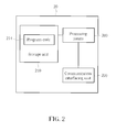
- Fig. 2 is a schematic diagram of a communication apparatus 20 according to an example of the present invention.
- the communication apparatus 20 can be one of the communication devices shown in Fig. 1 , such as a user equipment, but is not limited herein.
- the communication apparatus 20 may include a processing means 200 such as a microprocessor or Application Specific Integrated Circuit (ASIC), a storage unit 210 and a communication interfacing unit 220.
- the storage unit 210 may be any data storage device that can store a program code 214, accessed and executed by the processing means 200.
- Examples of the storage unit 210 include but are not limited to read-only memory (ROM), flash memory, random-access memory (RAM), Compact Disc Read-Only Memory (CD-ROM)/Digital Video Disc-Read Only Memory (DVD-ROM), magnetic tape, hard disk and optical data storage device.
- the communication interfacing unit 220 is preferably a transceiver and is used to transmit and receive signals (e.g., messages or packets) according to processing results of the processing means 200.
- Fig. 3 is a flowchart of a process 30 according to an example of the present invention.
- the process 30 is utilized in the wireless communication system 10 shown in Fig. 1 , for sending a feedback report in one of the communication devices to enhance performance of downlink multi-user multiple-input-multiple-output (MIMO) transmissions from the network to the communication devices.
- MIMO multiple-input-multiple-output
- the process 30 can be implemented in the communication apparatus 20 and may be compiled into the program code 214.
- the process 30 includes the following steps:
- the communication device generates the feedback report comprising the PMI, the BCI, the MU-CQI and the CVT and further transmits the feedback report to the network. Therefore, the network is able to perform appropriate modulation and coding scheme (MCS) selection and suitable mode selection from single-user MIMO (SU-MIMO) mode and multi-user MIMO (MU-MIMO) mode for the communication device, to enhance the performance of the downlink MIMO transmissions.
- MCS modulation and coding scheme
- the MU-CQI may be derived from a CQI function of the PMI and the BCI
- the CVT may be derived from a CQI function of the PMI, the BCI and any other precoder in a codebook other than the BCI.
- the CVT can be derived according to each of the following four algorithms:
- ⁇ ' denotes the MU-CQI
- h denotes the spatial channel vector between a transmitter and a receiver
- W PMI and W INTI denote the precoders that filter the signal and interference (i.e. W PMI is the PMI and W INTI is the BCI or the any other precoder in the codebook other than the PMI herein)
- ⁇ 2 denotes additive noise power
- Q CQI denotes a specified function of quantization.
- the CVT c can be defined as the lowest cross-correlation between an entry of the codebook W N _ BCI and the BCI W BCI that retains the validity of MU-CQI or maintains the deviation of MU-CQI within the pre-defined deviation value ⁇ . Therefore, the network can determine if the reported MU-CQI ⁇ is still valid according to the reported CVT c when the communication device is not paired with its favorite partner, and further decide to change the MCS or to switch between the SU-MIMO mode and the MU-MIMO mode in a precise manner.
- the CVT c can be defined as the lowest cross-correlation between an entry of the codebook W N_PMI and the PMI W PMI that retains the validity or maintains the deviation within the pre-defined deviation value ⁇ . Therefore, the network can determine if the reported MU-CQI ⁇ is still valid according to the reported CVT c when the communication device is paired without applying the reported PMI, and further decide to change the MCS or to switch between the SU-MIMO mode and the MU-MIMO mode in a precise manner.
- SU-CQI single-user MIMO assumption
- * denotes the complex-conjugate operation
- the function q denotes the CQI function as shown above.
- the CVT c can be defined as the lowest cross-correlation between an entry of the codebook W N_BCI and the BCI W BCI that maintains the difference between the SU-CQI ⁇ 0 and the reported MU-CQI ⁇ within the pre-defined deviation value ⁇ ⁇ . Therefore, the network can determine the lower bound of compromising the reported BCI W BCI that retains the motivation of MU-MIMO operation. In other words, the network can switch to the SU-MIMO mode if the lower bound is not fulfilled.
- SU-CQI single-user MIMO assumption
- * denotes the complex-conjugate operation
- the function q denotes the CQI function as shown above.
- the CVT c can be defined as the lowest cross-correlation between an entry of the codebook W N_PMI and the PMI W PMI that maintains the difference between the SU-CQI ⁇ 0 and the reported MU-CQI ⁇ within the pre-defined deviation value ⁇ ⁇ . Therefore, the network can determine the lower bound of compromising the reported BCI W BCI that retains the motivation of MU-MIMO operation. Besides, the network can switch to the SU-MIMO mode if the lower bound is not fulfilled.
- the process 30 is an example of the present invention, and those skilled in the art should readily make combinations, modifications and/or alterations on the abovementioned description and examples.
- the transmission of the feedback report can be triggered automatically or triggered by the network via broadcast messages or other higher layer signaling.
- the feedback report can be carried in messages via high layer signaling, such as measurement reports.
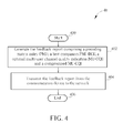
- Fig. 4 is a flowchart of a process 40 according to an example of the present invention.
- the process 40 is utilized in the wireless communication system 10 shown in Fig. 1 , for sending a feedback report in one of the communication devices to enhance performance of downlink MIMO transmissions from the network to the communication devices.
- the process 40 can be implemented in the communication apparatus 20 and may be compiled into the program code 214.
- the process 40 includes the following steps:
- the communication device generates the feedback report comprising the PMI, the BCI, the optimal MU-CQI and the compromised MU-CQI and further transmits the feedback report to the network. Therefore, the network is able to perform appropriate MCS selection and suitable mode selection from the SU-MIMO mode and the MU-MIMO mode for the communication devices, to enhance the performance of the downlink MIMO transmissions.
- the process 30 and the process 40 are similar.
- the difference between the process 30 and the process 40 is that the feedback report in the process 40 includes the compromised MU-CQI instead of the CVT in the process 30.
- the optimal MU-CQI is derived from a CQI function of the PMI and the BCI
- the compromised MU-CQI is derived from a CQI function of the PMI, the BCI and any other precoder in a codebook other than the BCI.
- the derivation of the optimal MU-CQI is the same as that of the MU-CQI in the process 30, and the compromised MU-CQI is derived according to each of the following two algorithms:
- ⁇ com denotes the compromised MU-CQI
- W PMI denotes the PMI
- W BCI denotes the BCI
- j denotes the precoder entry index in the codebook
- r denotes a cross-correlation threshold for the PMI
- * denotes the complex-conjugate operation
- the function q denotes the CQI function as shown above.
- the communication device identifies a subset of precoders such that one precoder in the subset has a higher cross-correlation level with the reported PMI W PMI than the cross-correlation threshold r.
- the communication device further calculates the lowest MU-CQI among all precoders in the subset, which is regarded as the compromised MU-CQI ⁇ com .
- the communication device provides the upper bound and the lower bound of the MU-CQI (i.e. the optimal MU-CQI ⁇ is the upper bound and the compromised MU-CQI ⁇ com is the lower bound) for the network. Therefore, the network can choose suitable MCS even if the communication device is not paired with the reported BCI W BCI .
- ⁇ com denotes the compromised MU-CQI
- W PMI denotes the PMI
- W BCI denotes the BCI
- j denotes the precoder entry index in the codebook
- r denotes a cross-correlation threshold for the PMI
- * denotes the complex-conjugate operation
- the function q denotes the CQI function as shown above.
- the communication device identifies a subset of precoders such that one precoder in the subset has a higher cross-correlation level with the reported BCI W BCI than the cross-correlation threshold r.
- the communication device further calculates the lowest MU-CQI among all precoders in the subset as the compromised MU-CQI.
- the communication device provides the upper bound and the lower bound of the MU-CQI (i.e. the optimal MU-CQI ⁇ is the upper bound and the compromised MU-CQI ⁇ com is the lower bound) for the network. Therefore, the network can choose suitable MCS even if the communication device is not paired with the reported PMI W PMI .
- the process 40 is an example of the present invention, and those skilled in the art should readily make combinations, modifications and/or alterations on the abovementioned description and examples.
- the cross-correlation threshold r can be configured by the network such as using radio resource controller (RRC) messages, which can be broadcast messages or higher layer signaling.
- RRC radio resource controller
- the cross-correlation threshold r can also be pre-defined in the specification of the 3rd Generation Partnership Project (3GPP) standard.
- the communication devices provide feedback reports for the network so that the network can perform appropriate MCS selection and suitable mode selection from the SU-MIMO mode and the MU-MIMO mode for the communication devices. Therefore, the performance of the downlink MIMO transmissions can be improved.
- the present invention provides a method for sending feedback reports from the communication devices to the network, to have the appropriate MCS selection and suitable mode selection from the SU-MIMO mode and the MU-MIMO mode for the communication devices, and further improve the performance of the downlink MIMO transmissions.
Landscapes
- Engineering & Computer Science (AREA)
- Signal Processing (AREA)
- Computer Networks & Wireless Communication (AREA)
- Physics & Mathematics (AREA)
- Mathematical Physics (AREA)
- Mobile Radio Communication Systems (AREA)
- Transmitters (AREA)
Abstract
Description
- The application relates to a method and apparatus utilized in a wireless communication system, and more particularly, to a method and apparatus of enhancing performance of downlink multi-user multiple-input-multiple-output transmissions in a wireless communication system.
- A long-term evolution (LTE) system supporting the 3GPP Rel-8 standard and/or the 3GPP Rel-9 standard are developed by the 3rd Generation Partnership Project (3GPP) as a successor of a universal mobile telecommunication system (UMTS) for further enhancing performance of the UMTS to satisfy increasing needs of users. The LTE system includes a new radio interface and a new radio network architecture that provides high data rate, low latency, packet optimization, and improved system capacity and coverage. In the LTE system, a radio access network known as an evolved universal terrestrial radio access network (E-UTRAN) includes multiple evolved Node-Bs (eNBs) for communicating with multiple user equipments (UEs), and communicating with a core network including a mobility management entity (MME), a serving gateway, etc., for Non-Access Stratum (NAS) control.
- A LTE-advanced (LTE-A) system, as its name implies, is an evolution of the LTE system. The LTE-A system targets faster switching between power states, improves performance at the coverage edge of an eNB, and includes advanced techniques, such as carrier aggregation (CA), coordinated multipoint transmission/reception (CoMP), uplink (UL) multiple-input multiple-output (MIMO), downlink multi-user MIMO (MU-MIMO), etc. For a UE and an eNB to communicate with each other in the LTE-A system, the UE and the eNB must support standards developed for the LTE-A system, such as the 3GPP Rel-10 standard or later versions.
- The downlink MU-MIMO technique, which is an advanced multi-antenna technique, can be used in an eNB to simultaneously transmit independent data to a plurality of UEs in the same frequency resources. A precoder is constructed to implement the downlink MU-MIMO technique. In other words, the construction of the precoder is based on feedback information from the UEs and regarded as an essential key to implement the downlink MU-MIMO technique. Therefore, each of the UEs should respectively send its favorite precoder index as well as the channel quality indication (CQI), to assist the eNB to construct a precoder matrix for downlink MU-MIMO transmissions.
- Since a potential interference may exist in a paired UE assigned in a downlink MU-MIMO transmission, a resultant performance may be degraded due to over-estimated CQI and inappropriate modulation and coding schemes (MCS) assignment, and/or unsuitable mode selection from single-user MIMO (SU-MIMO) mode and MU-MIMO mode. Therefore, the standardization of 3GPP LTE has provided several directions for MU-MIMO enhancements, such as additional feedback with a precoder matrix index (PMI), a best companion PMI (BCI) and a multi-user CQI (MU-CQI). Generally speaking, PMI represents the precoder to be applied at the eNB that maximizes the signal power with respect to the UE, and BCI represents the precoder for the paired UE at the eNB that causes least interference to the UE. In addition, MU-CQI is the CQI derived by taking interference from the paired UE into account.
- Besides, a paper, "Y.Du, J. Tong, J Zhang and S. Liu, 'Evaluation of PMI Feedback Schemes for MU-MIMO Pairing', IEEE Systems Journal, vol. 4, No. 4, pp.505-510, Dec. 2010", has provided a feedback method for a UE. In this paper, a codebook of the precoder is divided into several clusters, each cluster consists of multiple codebook entries, and an index of the best companion cluster (BCC) is as a feedback instead of the BCI. The index of the BCC corresponds to a precoder cluster that contains a desirable BCI, and the eNB treats all entries in the BCC as the feasible companion precoders that can be paired with the UE. Besides, the MU-CQI is reported based on the average among all candidate companion precoders in the BCC.
- Since the number of the BCCs is smaller than the codebook size, the approach provides scheduling flexibility while reducing feedback overhead. However, the method in the paper cannot capture the true degradation in the MU-CQI and the codebook clustering is specified offline, so that the performance of the method would be dramatically deteriorated when some of the more advanced precoding techniques are introduced in the future wireless communication systems. Therefore, it is necessary to provide other feedback methods to optimize the construction of the precoder.
- This in mind, the application aims at providing a method in a wireless communication system in order to solve the abovementioned problems.
- This is achieved by a method according to claim 1. The dependent claims pertain to corresponding further developments and improvements.
- As will be seen more clearly from the detailed description following below, the claimed method includes the method including generating a feedback report comprising a correlation-based validity threshold (CVT); and transmitting the feedback report from the communication device to the network.
- In another aspect, as will be seen more clearly from the detailed description following below, the claimed method includes generating a feedback report comprising a compromised MU-CQI; and transmitting the feedback report from the communication device to the network.
- In another aspect, as will be seen more clearly from the detailed description following below, the claimed communication apparatus includes a processing means; a storage unit; and a program code, stored in the storage unit, wherein the program code instructs the processing means to execute the following steps: generating a feedback report comprising a CVT; and transmitting the feedback report from a communication device to a network.
- In another aspect, as will be seen more clearly from the detailed description following below, the claimed communication apparatus includes a processing means; a storage unit; and a program code, stored in the storage unit, wherein the program code instructs the processing means to execute the following steps: generating a feedback report comprising a compromised MU-CQI; and transmitting the feedback report from a communication device to a network.
-
-
Fig. 1 is a schematic diagram of a wireless communication system according to an example of the present invention. -
Fig. 2 is a schematic diagram of a communication apparatus according to an example of the present invention. -
Fig. 3 is a flowchart of a process according to an example of the present invention. -
Fig. 4 is a flowchart of a process according to an example of the present invention. - Please refer to
Fig. 1 , which is a schematic diagram of awireless communication system 10 according to an example of the present invention. Thewireless communication system 10 is briefly composed of a network and a plurality of communication devices. InFig. 1 , the network and the communication devices are simply utilized for illustrating the structure of thewireless communication system 10. Practically, the network can be a universal terrestrial radio access network (UTRAN) comprising a plurality of Node-Bs (NBs) in a universal mobile telecommunications system (UMTS). Alternatively, the network can be an evolved UTRAN (E-UTRAN) comprising a plurality of evolved NBs (eNBs) and/or relays in a long term evolution (LTE) system or a LTE-Advanced (LTE-A) system. - Furthermore, the network can also include both the UTRAN/E-UTRAN and a core network, wherein the core network includes network entities such as Mobility Management Entity (MME), Serving Gateway (S-GW), Packet Data Network (PDN) Gateway (P-GW), Self-Organizing Networks (SON) server and/or Radio Network Controller (RNC), etc. In other words, after the network receives information transmitted by a communication device, the information may be processed only by the UTRAN/E-UTRAN and decisions corresponding to the information are made at the UTRAN/E-UTRAN. Alternatively, the UTRAN/E-UTRAN may forward the information to the core network, and the decisions corresponding to the information are made at the core network after the core network processes the information. Besides, the information can be processed by both the UTRAN/E-UTRAN and the core network, and the decisions are made after coordination and/or cooperation are performed by the UTRAN/E-UTRAN and the core network.
- The communication devices can be mobile communication devices such as user equipments for performing speech and data communication through the network such as the UMTS, the LTE system or the LTE-A system. Besides, the network and a communication device can be seen as a transmitter or a receiver according to transmission direction, e.g., for an uplink (UL), the communication device is the transmitter and the network is the receiver, and for a downlink (DL), the network is the transmitter and the communication device is the receiver.
- Please refer to
Fig. 2 , which is a schematic diagram of acommunication apparatus 20 according to an example of the present invention. Thecommunication apparatus 20 can be one of the communication devices shown inFig. 1 , such as a user equipment, but is not limited herein. Thecommunication apparatus 20 may include a processing means 200 such as a microprocessor or Application Specific Integrated Circuit (ASIC), astorage unit 210 and acommunication interfacing unit 220. Thestorage unit 210 may be any data storage device that can store aprogram code 214, accessed and executed by the processing means 200. Examples of thestorage unit 210 include but are not limited to read-only memory (ROM), flash memory, random-access memory (RAM), Compact Disc Read-Only Memory (CD-ROM)/Digital Video Disc-Read Only Memory (DVD-ROM), magnetic tape, hard disk and optical data storage device. Thecommunication interfacing unit 220 is preferably a transceiver and is used to transmit and receive signals (e.g., messages or packets) according to processing results of the processing means 200. - Please refer to
Fig. 3 , which is a flowchart of aprocess 30 according to an example of the present invention. Theprocess 30 is utilized in thewireless communication system 10 shown inFig. 1 , for sending a feedback report in one of the communication devices to enhance performance of downlink multi-user multiple-input-multiple-output (MIMO) transmissions from the network to the communication devices. Theprocess 30 can be implemented in thecommunication apparatus 20 and may be compiled into theprogram code 214. Theprocess 30 includes the following steps: - Step 300:
- Start.
- Step 302:
- Generate the feedback report comprising a precoding matrix index (PMI), a best companion PMI (BCI), a multi-user channel quality indication (MU-CQI) and a correlation-based validity threshold (CVT).
- Step 304:
- Transmit the feedback report from the communication device to the network.
- Step 306:
- End.
- According to the
process 30, the communication device generates the feedback report comprising the PMI, the BCI, the MU-CQI and the CVT and further transmits the feedback report to the network. Therefore, the network is able to perform appropriate modulation and coding scheme (MCS) selection and suitable mode selection from single-user MIMO (SU-MIMO) mode and multi-user MIMO (MU-MIMO) mode for the communication device, to enhance the performance of the downlink MIMO transmissions. - In the
process 30, the MU-CQI may be derived from a CQI function of the PMI and the BCI, and the CVT may be derived from a CQI function of the PMI, the BCI and any other precoder in a codebook other than the BCI. For example, the MU-CQI can be determined by the following equations:
wherein ξ denotes the MU-CQI, h denotes the spatial channel vector between a transmitter and a receiver, WPMI denotes the PMI, WBCI denotes the BCI, σ2 denotes additive noise power, and QCQI denotes a specified function of quantization. In this regard, the CVT can be derived according to each of the following four algorithms: -

wherein c denotes the CVT, WPMI denotes the PMI, WBCI denotes the BCI, WN_ECI denotes the any other precoder in the codebook other than the BCI, Δζ denotes a pre-defined deviation value, * denotes the complex-conjugate operation, and the function q denotes a CQI function. Besides, the CQI function is determined as the following equations:
wherein ξ' denotes the MU-CQI, h denotes the spatial channel vector between a transmitter and a receiver, WPMI and WINTI denote the precoders that filter the signal and interference (i.e. WPMI is the PMI and WINTI is the BCI or the any other precoder in the codebook other than the PMI herein), σ2 denotes additive noise power, and QCQI denotes a specified function of quantization. - In detail, the CVT c can be defined as the lowest cross-correlation between an entry of the codebook W N_BCI and the BCI WBCI that retains the validity of MU-CQI or maintains the deviation of MU-CQI within the pre-defined deviation value Δξ. Therefore, the network can determine if the reported MU-CQI ξ is still valid according to the reported CVT c when the communication device is not paired with its favorite partner, and further decide to change the MCS or to switch between the SU-MIMO mode and the MU-MIMO mode in a precise manner.
-

wherein c denotes the CVT, WPMI denotes the PMI, WBCI denotes the BCI, WN_PMI denotes the any other precoder in the codebook other than the PMI, Δξ denotes the pre-defined deviation value, * denotes the complex-conjugate operation, and the function q denotes the CQI function as shown above. - In detail, the CVT c can be defined as the lowest cross-correlation between an entry of the codebook WN_PMI and the PMI WPMI that retains the validity or maintains the deviation within the pre-defined deviation value Δξ. Therefore, the network can determine if the reported MU-CQI ξ is still valid according to the reported CVT c when the communication device is paired without applying the reported PMI, and further decide to change the MCS or to switch between the SU-MIMO mode and the MU-MIMO mode in a precise manner.
-

wherein c denotes the CVT, WPMI denotes the PMI, WBCI denotes the BCI, WN_BCI denotes the any other precoder in the codebook other than the BCI, ξ0 denotes the CQI under single-user MIMO assumption (SU-CQI), Δξ denotes the pre-defined deviation value, * denotes the complex-conjugate operation, and the function q denotes the CQI function as shown above. - In detail, the CVT c can be defined as the lowest cross-correlation between an entry of the codebook WN_BCI and the BCI WBCI that maintains the difference between the SU-CQI ξ 0 and the reported MU-CQI ξ within the pre-defined deviation value Δξ. Therefore, the network can determine the lower bound of compromising the reported BCI WBCI that retains the motivation of MU-MIMO operation. In other words, the network can switch to the SU-MIMO mode if the lower bound is not fulfilled.
-

wherein c denotes the CVT, WPMI denotes the PMI, WBCI denotes the BCI, WN_PMI denotes the any other precoder in the codebook other than the PMI, ξ0 denotes the CQI under single-user MIMO assumption (SU-CQI), Δξ denotes the pre-defined deviation value, * denotes the complex-conjugate operation, and the function q denotes the CQI function as shown above. - In detail, the CVT c can be defined as the lowest cross-correlation between an entry of the codebook WN_PMI and the PMI WPMI that maintains the difference between the SU-CQI ξ 0 and the reported MU-CQI ξ within the pre-defined deviation value Δξ. Therefore, the network can determine the lower bound of compromising the reported BCI WBCI that retains the motivation of MU-MIMO operation. Besides, the network can switch to the SU-MIMO mode if the lower bound is not fulfilled.
- Note that, the
process 30 is an example of the present invention, and those skilled in the art should readily make combinations, modifications and/or alterations on the abovementioned description and examples. For example, the transmission of the feedback report can be triggered automatically or triggered by the network via broadcast messages or other higher layer signaling. Besides, the feedback report can be carried in messages via high layer signaling, such as measurement reports. - Please refer to
Fig. 4 , which is a flowchart of aprocess 40 according to an example of the present invention. Theprocess 40 is utilized in thewireless communication system 10 shown inFig. 1 , for sending a feedback report in one of the communication devices to enhance performance of downlink MIMO transmissions from the network to the communication devices. Theprocess 40 can be implemented in thecommunication apparatus 20 and may be compiled into theprogram code 214. Theprocess 40 includes the following steps: - Step 400:
- Start.
- Step 402:
- Generate the feedback report comprising a precoding matrix index (PMI), a best companion PMI (BCI), a optimal multi-user channel quality indication (MU-CQI) and a compromised MU-CQI.
- Step 404:
- Transmit the feedback report from the communication device to the network.
- Step 406:
- End.
- According to the
process 40, the communication device generates the feedback report comprising the PMI, the BCI, the optimal MU-CQI and the compromised MU-CQI and further transmits the feedback report to the network. Therefore, the network is able to perform appropriate MCS selection and suitable mode selection from the SU-MIMO mode and the MU-MIMO mode for the communication devices, to enhance the performance of the downlink MIMO transmissions. - The
process 30 and theprocess 40 are similar. The difference between theprocess 30 and theprocess 40 is that the feedback report in theprocess 40 includes the compromised MU-CQI instead of the CVT in theprocess 30. In detail, the optimal MU-CQI is derived from a CQI function of the PMI and the BCI, and the compromised MU-CQI is derived from a CQI function of the PMI, the BCI and any other precoder in a codebook other than the BCI. In other words, the derivation of the optimal MU-CQI is the same as that of the MU-CQI in theprocess 30, and the compromised MU-CQI is derived according to each of the following two algorithms: -

wherein ξ com denotes the compromised MU-CQI, WPMI denotes the PMI, WBCI denotes the BCI, j denotes the precoder entry index in the codebook, r denotes a cross-correlation threshold for the PMI, * denotes the complex-conjugate operation, and the function q denotes the CQI function as shown above. - In detail, the communication device identifies a subset of precoders such that one precoder in the subset has a higher cross-correlation level with the reported PMI WPMI than the cross-correlation threshold r. The communication device further calculates the lowest MU-CQI among all precoders in the subset, which is regarded as the compromised MU-CQI ξ com. In other words, the communication device provides the upper bound and the lower bound of the MU-CQI (i.e. the optimal MU-CQI ξ is the upper bound and the compromised MU-CQI ξ com is the lower bound) for the network. Therefore, the network can choose suitable MCS even if the communication device is not paired with the reported BCI WBCI.
-

wherein ξ com denotes the compromised MU-CQI, WPMI denotes the PMI, WBCI denotes the BCI, j denotes the precoder entry index in the codebook, r denotes a cross-correlation threshold for the PMI, * denotes the complex-conjugate operation, and the function q denotes the CQI function as shown above. - In detail, the communication device identifies a subset of precoders such that one precoder in the subset has a higher cross-correlation level with the reported BCI WBCI than the cross-correlation threshold r. The communication device further calculates the lowest MU-CQI among all precoders in the subset as the compromised MU-CQI. In other words, the communication device provides the upper bound and the lower bound of the MU-CQI (i.e. the optimal MU-CQI ξ is the upper bound and the compromised MU-CQI ξ com is the lower bound) for the network. Therefore, the network can choose suitable MCS even if the communication device is not paired with the reported PMI WPMI.
- Note that, the
process 40 is an example of the present invention, and those skilled in the art should readily make combinations, modifications and/or alterations on the abovementioned description and examples. For example, the cross-correlation threshold r can be configured by the network such as using radio resource controller (RRC) messages, which can be broadcast messages or higher layer signaling. The cross-correlation threshold r can also be pre-defined in the specification of the 3rd Generation Partnership Project (3GPP) standard. - In the present invention, the communication devices provide feedback reports for the network so that the network can perform appropriate MCS selection and suitable mode selection from the SU-MIMO mode and the MU-MIMO mode for the communication devices. Therefore, the performance of the downlink MIMO transmissions can be improved.
- To sum up, the present invention provides a method for sending feedback reports from the communication devices to the network, to have the appropriate MCS selection and suitable mode selection from the SU-MIMO mode and the MU-MIMO mode for the communication devices, and further improve the performance of the downlink MIMO transmissions.
Claims (17)
- A method of enhancing performance of downlink multi-user multiple-input-multiple-output (MIMO) transmissions in a wireless communication system comprising a communication device and a network, characterized by the method comprising:generating a feedback report comprising a correlation-based validity threshold (CVT) (302); andtransmitting the feedback report from the communication device to the network (304).
- A method of enhancing performance of downlink multi-user multiple-input-multiple-output transmissions in a wireless communication system comprising a communication device and a network, characterized by the method comprising:generating a feedback report comprising a compromised multi-user channel quality indication (MU-CQI) (402); andtransmitting the feedback report from the communication device to the network (404).
- A communication apparatus (20) for a wireless communication system, comprising:a processing means (200);a storage unit (210); anda program code (214), stored in the storage unit, characterized in that the program code instructs the processing means to execute the following steps:generating a feedback report comprising a correlation-based validity threshold (CVT) (302); andtransmitting the feedback report from a communication device to a network (304).
- A communication apparatus (20) for a wireless communication system, comprising:a processing means (200);a storage unit (210); anda program code (214), stored in the storage unit, characterized in that the program code instructs the processing means to execute the following steps:generating a feedback report comprising a compromised multi-user channel quality indication (MU-CQI) (402); andtransmitting the feedback report from a communication device to a network (404).
- The method of claim 1 or the communication apparatus of claim 3, characterized in that the feedback report further comprises a precoding matrix index (PMI), a best companion PMI (BCI) and a multi-user channel quality indication (MU-CQI).
- The method or the communication apparatus of claim 5, characterized in that the MU-CQI is derived from a channel quality indication (CQI) function of the PMI and the BCI.
- The method or the communication apparatus of claim 5, characterized in that the CVT is derived from a CQI function of the PMI, the BCI and any other precoder in a codebook other than the BCI.
- The method or the communication apparatus of claim 7, characterized in that the CVT is derived according to the following equations:

- The method or the communication apparatus of claim 7, characterized in that the CVT is derived according to the following equations:

- The method or the communication apparatus of claim 7, characterized in that the CVT is derived according to the following equations:

- The method or the communication apparatus of claim 7, characterized in that the CVT is derived according to the following equations:

- The method of claim 2 or the communication apparatus of claim 4, characterized in that the feedback report further comprises a precoding matrix index (PMI), a best companion PMI (BCI) and an optimal multi-user channel quality indication (MU-CQI).
- The method or the communication apparatus of claim 12, characterized in that the optimal MU-CQI is derived from a CQI function of the PMI and the BCI.
- The method or the communication apparatus of claim 12, characterized in that the compromised MU-CQI is derived from a CQI function of the PMI, the BCI and any other precoder in a codebook other than the BCI.
- The method or the communication apparatus of claim 14, characterized in that the compromised MU-CQI is derived from a cross-correlation threshold which is configured by the network or pre-defined in the specification.
- The method or the communication apparatus of claim 15, characterized in that the compromised MU-CQI is derived according to the following equations:

- The method or the communication apparatus of claim 15, characterized in that the compromised MU-CQI is derived according to the following equations:

wherein ξ com denotes the compromised MU-CQI, WPMI denotes the PMI, WBCI denotes the BCI, j denotes the precoder entry index in the codebook, r denotes the cross-correlation threshold for the PMI, * denotes the complex-conjugate operation, and the function q denotes a CQI function.
Applications Claiming Priority (2)
| Application Number | Priority Date | Filing Date | Title |
|---|---|---|---|
| US201261607016P | 2012-03-06 | 2012-03-06 | |
| US13/747,482 US9014150B2 (en) | 2012-03-06 | 2013-01-23 | Method and apparatus of enhancing performance of downlink multi-user multiple-input-multiple-output transmissions in wireless communication system |
Publications (4)
| Publication Number | Publication Date |
|---|---|
| EP2637346A2 true EP2637346A2 (en) | 2013-09-11 |
| EP2637346A3 EP2637346A3 (en) | 2016-06-15 |
| EP2637346B1 EP2637346B1 (en) | 2018-08-15 |
| EP2637346B8 EP2637346B8 (en) | 2018-10-24 |
Family
ID=47632928
Family Applications (1)
| Application Number | Title | Priority Date | Filing Date |
|---|---|---|---|
| EP13153970.2A Active EP2637346B8 (en) | 2012-03-06 | 2013-02-05 | Method and apparatus of enhancing performance of downlink multi-user multiple-input-multiple-output transmissions in wireless communication system |
Country Status (4)
| Country | Link |
|---|---|
| US (1) | US9014150B2 (en) |
| EP (1) | EP2637346B8 (en) |
| CN (1) | CN103312403B (en) |
| TW (1) | TWI486015B (en) |
Families Citing this family (1)
| Publication number | Priority date | Publication date | Assignee | Title |
|---|---|---|---|---|
| US20130324120A1 (en) * | 2012-05-31 | 2013-12-05 | Federico Boccardi | Local operational data upload |
Family Cites Families (15)
| Publication number | Priority date | Publication date | Assignee | Title |
|---|---|---|---|---|
| US20080198796A1 (en) * | 2007-02-16 | 2008-08-21 | Yu-Chih Jen | Method and Apparatus for Enhancing System Efficiency in a Wireless Communications System |
| KR100962037B1 (en) * | 2007-03-14 | 2010-06-08 | 이노베이티브 소닉 리미티드 | Method and apparatus for setting transport block size in wireless communication system |
| WO2008113210A1 (en) * | 2007-03-20 | 2008-09-25 | Huawei Technologies Co., Ltd. | Channel quality estimation in a multiple user multiple input multiple output wireless system |
| CN101400074A (en) * | 2007-09-28 | 2009-04-01 | 夏普株式会社 | Method, user equipment and system for reducing feedback quantity of pre-coding matrix index number |
| KR101587005B1 (en) * | 2009-03-11 | 2016-02-02 | 삼성전자주식회사 | Method and apparatus for transmitting control information for interference mitigation in a multi-antenna system |
| US8526519B2 (en) * | 2009-12-14 | 2013-09-03 | Texas Instruments Incorporated | Multi-rank precoding matrix indicator (PMI) feedback in a multiple-input multiple-output (MIMO) system |
| US20110170427A1 (en) * | 2010-01-11 | 2011-07-14 | Nokia Corporation | Best Companion PMI-Based Beamforming |
| US8406332B2 (en) * | 2010-01-18 | 2013-03-26 | Research In Motion Limited | Downlink transmission in a multiple-user multiple-input multiple-output (“MU-MIMO”) wireless communication system |
| US8644422B2 (en) * | 2010-02-12 | 2014-02-04 | Blackberry Limited | Low overhead PMI and CQI feedback and pairing schemes for MU-MIMO |
| EP2375581B1 (en) * | 2010-04-01 | 2012-12-26 | Alcatel Lucent | Feedback for multi-user MIMO systems |
| JP5268983B2 (en) * | 2010-04-05 | 2013-08-21 | 株式会社エヌ・ティ・ティ・ドコモ | COMMUNICATION CONTROL METHOD, MOBILE STATION DEVICE, AND BASE STATION DEVICE |
| US8644180B2 (en) * | 2010-04-05 | 2014-02-04 | Nec Laboratories America, Inc. | MU-MIMO-OFDMA methods and systems for signaling multi-rank CQIs and precoders |
| US9203552B2 (en) * | 2010-09-08 | 2015-12-01 | Qualcomm Incorporated | Unified feedback framework for MU-MIMO enhancement based on indication of preferred precoder pairings |
| KR101752824B1 (en) * | 2010-09-29 | 2017-06-30 | 삼성전자주식회사 | Method and apparatus for feedback in multi user-multiple input multiple output system |
| US20120314590A1 (en) * | 2011-06-10 | 2012-12-13 | Sharp Laboratories Of America, Inc. | Enhanced precoding feedback for multiple-user multiple-input and multiple-output (mimo) |
-
2013
- 2013-01-23 US US13/747,482 patent/US9014150B2/en active Active
- 2013-02-05 EP EP13153970.2A patent/EP2637346B8/en active Active
- 2013-03-06 TW TW102107858A patent/TWI486015B/en active
- 2013-03-06 CN CN201310071473.6A patent/CN103312403B/en active Active
Non-Patent Citations (1)
| Title |
|---|
| Y.DU; J. TONG; J ZHANG; S. LIU: "Evaluation of PMI Feedback Schemes for MU-MIMO Pairing", IEEE SYSTEMS JOURNAL, vol. 4, no. 4, December 2010 (2010-12-01), pages 505 - 510, XP011320688 |
Also Published As
| Publication number | Publication date |
|---|---|
| EP2637346B8 (en) | 2018-10-24 |
| EP2637346B1 (en) | 2018-08-15 |
| CN103312403B (en) | 2016-05-25 |
| US20130235815A1 (en) | 2013-09-12 |
| TWI486015B (en) | 2015-05-21 |
| TW201338456A (en) | 2013-09-16 |
| CN103312403A (en) | 2013-09-18 |
| US9014150B2 (en) | 2015-04-21 |
| EP2637346A3 (en) | 2016-06-15 |
Similar Documents
| Publication | Publication Date | Title |
|---|---|---|
| US9392607B2 (en) | Two-dimensional UE pairing in MIMO systems | |
| JP5905484B2 (en) | Apparatus and method for periodic channel state reporting in a wireless network | |
| US9872190B2 (en) | Method for reporting channel quality information and device thereof | |
| US20120270535A1 (en) | Implicit CSI Feedback for DL Multiuser MIMO Transmission | |
| EP3310090A1 (en) | User terminal, wireless base station, and wireless communication method | |
| CN102550072A (en) | Wireless base station device, mobile terminal device, and wireless communication method | |
| US20160134342A1 (en) | Adaptive MIMO Feasibility feedback | |
| CN110212958A (en) | Channel information feedback method and device in a kind of mobile communication system | |
| EP2695341A1 (en) | Methods, apparatuses, and systems for flexible rank adaptation in a wireless communication network | |
| KR20130038044A (en) | Method and apparatus for transmitting/receiving channel status information of downlink channel in a mobile communication system | |
| US20170085302A1 (en) | Wireless communication device and method of controlling signal processing | |
| EP3282609A1 (en) | Radio base station, user terminal, radio communication system and radio communication method | |
| WO2013055093A1 (en) | Method and apparatus for reporting channel state information in a wireless communication system | |
| WO2022032424A1 (en) | Procedures for port-selection codebook with frequency selective precoded reference signals | |
| CN104662953B (en) | The feedback method and device of channel state information | |
| EP3306830A1 (en) | Method and apparatus for transmitting and receiving channel information in inter-vehicle communication system | |
| CN115021790B (en) | A method and device used in a node for wireless communication | |
| WO2016024972A1 (en) | Pmi selection | |
| CN111817829B (en) | Method and apparatus in a node used for wireless communication | |
| EP2750302B1 (en) | Method of Handling Multiuser CQI for MU-MIMO and Related Communication Device | |
| EP2637346B1 (en) | Method and apparatus of enhancing performance of downlink multi-user multiple-input-multiple-output transmissions in wireless communication system | |
| CN112491453B (en) | Method and device used in user equipment and base station for wireless communication | |
| CN112153597A (en) | A method and apparatus used in a node for wireless communication | |
| EP3300273A1 (en) | User terminal, wireless base station, and wireless communication method | |
| KR20250164154A (en) | Method and device used in a node for wireless communication |
Legal Events
| Date | Code | Title | Description |
|---|---|---|---|
| PUAI | Public reference made under article 153(3) epc to a published international application that has entered the european phase |
Free format text: ORIGINAL CODE: 0009012 |
|
| AK | Designated contracting states |
Kind code of ref document: A2 Designated state(s): AL AT BE BG CH CY CZ DE DK EE ES FI FR GB GR HR HU IE IS IT LI LT LU LV MC MK MT NL NO PL PT RO RS SE SI SK SM TR |
|
| AX | Request for extension of the european patent |
Extension state: BA ME |
|
| RIC1 | Information provided on ipc code assigned before grant |
Ipc: H04B 7/06 20060101ALI20160121BHEP Ipc: H04L 5/00 20060101AFI20160121BHEP Ipc: H04B 7/04 20060101ALI20160121BHEP |
|
| PUAL | Search report despatched |
Free format text: ORIGINAL CODE: 0009013 |
|
| AK | Designated contracting states |
Kind code of ref document: A3 Designated state(s): AL AT BE BG CH CY CZ DE DK EE ES FI FR GB GR HR HU IE IS IT LI LT LU LV MC MK MT NL NO PL PT RO RS SE SI SK SM TR |
|
| AX | Request for extension of the european patent |
Extension state: BA ME |
|
| RIC1 | Information provided on ipc code assigned before grant |
Ipc: H04L 5/00 20060101AFI20160512BHEP Ipc: H04B 7/06 20060101ALI20160512BHEP Ipc: H04B 7/04 20060101ALI20160512BHEP |
|
| STAA | Information on the status of an ep patent application or granted ep patent |
Free format text: STATUS: REQUEST FOR EXAMINATION WAS MADE |
|
| 17P | Request for examination filed |
Effective date: 20161202 |
|
| RBV | Designated contracting states (corrected) |
Designated state(s): AL AT BE BG CH CY CZ DE DK EE ES FI FR GB GR HR HU IE IS IT LI LT LU LV MC MK MT NL NO PL PT RO RS SE SI SK SM TR |
|
| STAA | Information on the status of an ep patent application or granted ep patent |
Free format text: STATUS: EXAMINATION IS IN PROGRESS |
|
| 17Q | First examination report despatched |
Effective date: 20170207 |
|
| REG | Reference to a national code |
Ref country code: DE Ref legal event code: R079 Ref document number: 602013041909 Country of ref document: DE Free format text: PREVIOUS MAIN CLASS: H04L0005000000 Ipc: H04W0024020000 |
|
| RIC1 | Information provided on ipc code assigned before grant |
Ipc: H04B 7/06 20060101ALI20180215BHEP Ipc: H04W 24/02 20090101AFI20180215BHEP Ipc: H04B 7/0417 20170101ALI20180215BHEP Ipc: H04L 5/00 20060101ALI20180215BHEP Ipc: H04B 7/0452 20170101ALI20180215BHEP |
|
| GRAP | Despatch of communication of intention to grant a patent |
Free format text: ORIGINAL CODE: EPIDOSNIGR1 |
|
| STAA | Information on the status of an ep patent application or granted ep patent |
Free format text: STATUS: GRANT OF PATENT IS INTENDED |
|
| INTG | Intention to grant announced |
Effective date: 20180321 |
|
| GRAS | Grant fee paid |
Free format text: ORIGINAL CODE: EPIDOSNIGR3 |
|
| GRAA | (expected) grant |
Free format text: ORIGINAL CODE: 0009210 |
|
| STAA | Information on the status of an ep patent application or granted ep patent |
Free format text: STATUS: THE PATENT HAS BEEN GRANTED |
|
| AK | Designated contracting states |
Kind code of ref document: B1 Designated state(s): AL AT BE BG CH CY CZ DE DK EE ES FI FR GB GR HR HU IE IS IT LI LT LU LV MC MK MT NL NO PL PT RO RS SE SI SK SM TR |
|
| REG | Reference to a national code |
Ref country code: CH Ref legal event code: EP Ref country code: GB Ref legal event code: FG4D Ref country code: AT Ref legal event code: REF Ref document number: 1031223 Country of ref document: AT Kind code of ref document: T Effective date: 20180815 |
|
| REG | Reference to a national code |
Ref country code: IE Ref legal event code: FG4D |
|
| REG | Reference to a national code |
Ref country code: DE Ref legal event code: R081 Ref document number: 602013041909 Country of ref document: DE Owner name: ACER INCORPORATED, TW Free format text: FORMER OWNER: INDUSTRIAL TECHNOLOGY RESEARCH INSTITUTE, CHUTUNG, HSINCHU, TW |
|
| REG | Reference to a national code |
Ref country code: DE Ref legal event code: R096 Ref document number: 602013041909 Country of ref document: DE |
|
| RAP2 | Party data changed (patent owner data changed or rights of a patent transferred) |
Owner name: ACER INCORPORATED |
|
| REG | Reference to a national code |
Ref country code: CH Ref legal event code: PK Free format text: BERICHTIGUNG B8 |
|
| REG | Reference to a national code |
Ref country code: NL Ref legal event code: MP Effective date: 20180815 |
|
| REG | Reference to a national code |
Ref country code: LT Ref legal event code: MG4D |
|
| REG | Reference to a national code |
Ref country code: AT Ref legal event code: MK05 Ref document number: 1031223 Country of ref document: AT Kind code of ref document: T Effective date: 20180815 |
|
| PG25 | Lapsed in a contracting state [announced via postgrant information from national office to epo] |
Ref country code: FI Free format text: LAPSE BECAUSE OF FAILURE TO SUBMIT A TRANSLATION OF THE DESCRIPTION OR TO PAY THE FEE WITHIN THE PRESCRIBED TIME-LIMIT Effective date: 20180815 Ref country code: RS Free format text: LAPSE BECAUSE OF FAILURE TO SUBMIT A TRANSLATION OF THE DESCRIPTION OR TO PAY THE FEE WITHIN THE PRESCRIBED TIME-LIMIT Effective date: 20180815 Ref country code: IS Free format text: LAPSE BECAUSE OF FAILURE TO SUBMIT A TRANSLATION OF THE DESCRIPTION OR TO PAY THE FEE WITHIN THE PRESCRIBED TIME-LIMIT Effective date: 20181215 Ref country code: SE Free format text: LAPSE BECAUSE OF FAILURE TO SUBMIT A TRANSLATION OF THE DESCRIPTION OR TO PAY THE FEE WITHIN THE PRESCRIBED TIME-LIMIT Effective date: 20180815 Ref country code: BG Free format text: LAPSE BECAUSE OF FAILURE TO SUBMIT A TRANSLATION OF THE DESCRIPTION OR TO PAY THE FEE WITHIN THE PRESCRIBED TIME-LIMIT Effective date: 20181115 Ref country code: NL Free format text: LAPSE BECAUSE OF FAILURE TO SUBMIT A TRANSLATION OF THE DESCRIPTION OR TO PAY THE FEE WITHIN THE PRESCRIBED TIME-LIMIT Effective date: 20180815 Ref country code: LT Free format text: LAPSE BECAUSE OF FAILURE TO SUBMIT A TRANSLATION OF THE DESCRIPTION OR TO PAY THE FEE WITHIN THE PRESCRIBED TIME-LIMIT Effective date: 20180815 Ref country code: NO Free format text: LAPSE BECAUSE OF FAILURE TO SUBMIT A TRANSLATION OF THE DESCRIPTION OR TO PAY THE FEE WITHIN THE PRESCRIBED TIME-LIMIT Effective date: 20181115 Ref country code: GR Free format text: LAPSE BECAUSE OF FAILURE TO SUBMIT A TRANSLATION OF THE DESCRIPTION OR TO PAY THE FEE WITHIN THE PRESCRIBED TIME-LIMIT Effective date: 20181116 Ref country code: AT Free format text: LAPSE BECAUSE OF FAILURE TO SUBMIT A TRANSLATION OF THE DESCRIPTION OR TO PAY THE FEE WITHIN THE PRESCRIBED TIME-LIMIT Effective date: 20180815 |
|
| PG25 | Lapsed in a contracting state [announced via postgrant information from national office to epo] |
Ref country code: HR Free format text: LAPSE BECAUSE OF FAILURE TO SUBMIT A TRANSLATION OF THE DESCRIPTION OR TO PAY THE FEE WITHIN THE PRESCRIBED TIME-LIMIT Effective date: 20180815 Ref country code: LV Free format text: LAPSE BECAUSE OF FAILURE TO SUBMIT A TRANSLATION OF THE DESCRIPTION OR TO PAY THE FEE WITHIN THE PRESCRIBED TIME-LIMIT Effective date: 20180815 Ref country code: AL Free format text: LAPSE BECAUSE OF FAILURE TO SUBMIT A TRANSLATION OF THE DESCRIPTION OR TO PAY THE FEE WITHIN THE PRESCRIBED TIME-LIMIT Effective date: 20180815 |
|
| PG25 | Lapsed in a contracting state [announced via postgrant information from national office to epo] |
Ref country code: ES Free format text: LAPSE BECAUSE OF FAILURE TO SUBMIT A TRANSLATION OF THE DESCRIPTION OR TO PAY THE FEE WITHIN THE PRESCRIBED TIME-LIMIT Effective date: 20180815 Ref country code: EE Free format text: LAPSE BECAUSE OF FAILURE TO SUBMIT A TRANSLATION OF THE DESCRIPTION OR TO PAY THE FEE WITHIN THE PRESCRIBED TIME-LIMIT Effective date: 20180815 Ref country code: RO Free format text: LAPSE BECAUSE OF FAILURE TO SUBMIT A TRANSLATION OF THE DESCRIPTION OR TO PAY THE FEE WITHIN THE PRESCRIBED TIME-LIMIT Effective date: 20180815 Ref country code: IT Free format text: LAPSE BECAUSE OF FAILURE TO SUBMIT A TRANSLATION OF THE DESCRIPTION OR TO PAY THE FEE WITHIN THE PRESCRIBED TIME-LIMIT Effective date: 20180815 Ref country code: CZ Free format text: LAPSE BECAUSE OF FAILURE TO SUBMIT A TRANSLATION OF THE DESCRIPTION OR TO PAY THE FEE WITHIN THE PRESCRIBED TIME-LIMIT Effective date: 20180815 Ref country code: PL Free format text: LAPSE BECAUSE OF FAILURE TO SUBMIT A TRANSLATION OF THE DESCRIPTION OR TO PAY THE FEE WITHIN THE PRESCRIBED TIME-LIMIT Effective date: 20180815 |
|
| REG | Reference to a national code |
Ref country code: DE Ref legal event code: R097 Ref document number: 602013041909 Country of ref document: DE |
|
| PG25 | Lapsed in a contracting state [announced via postgrant information from national office to epo] |
Ref country code: SM Free format text: LAPSE BECAUSE OF FAILURE TO SUBMIT A TRANSLATION OF THE DESCRIPTION OR TO PAY THE FEE WITHIN THE PRESCRIBED TIME-LIMIT Effective date: 20180815 Ref country code: DK Free format text: LAPSE BECAUSE OF FAILURE TO SUBMIT A TRANSLATION OF THE DESCRIPTION OR TO PAY THE FEE WITHIN THE PRESCRIBED TIME-LIMIT Effective date: 20180815 Ref country code: SK Free format text: LAPSE BECAUSE OF FAILURE TO SUBMIT A TRANSLATION OF THE DESCRIPTION OR TO PAY THE FEE WITHIN THE PRESCRIBED TIME-LIMIT Effective date: 20180815 |
|
| PLBE | No opposition filed within time limit |
Free format text: ORIGINAL CODE: 0009261 |
|
| STAA | Information on the status of an ep patent application or granted ep patent |
Free format text: STATUS: NO OPPOSITION FILED WITHIN TIME LIMIT |
|
| 26N | No opposition filed |
Effective date: 20190516 |
|
| PG25 | Lapsed in a contracting state [announced via postgrant information from national office to epo] |
Ref country code: SI Free format text: LAPSE BECAUSE OF FAILURE TO SUBMIT A TRANSLATION OF THE DESCRIPTION OR TO PAY THE FEE WITHIN THE PRESCRIBED TIME-LIMIT Effective date: 20180815 |
|
| REG | Reference to a national code |
Ref country code: CH Ref legal event code: PL |
|
| PG25 | Lapsed in a contracting state [announced via postgrant information from national office to epo] |
Ref country code: LU Free format text: LAPSE BECAUSE OF NON-PAYMENT OF DUE FEES Effective date: 20190205 Ref country code: MC Free format text: LAPSE BECAUSE OF FAILURE TO SUBMIT A TRANSLATION OF THE DESCRIPTION OR TO PAY THE FEE WITHIN THE PRESCRIBED TIME-LIMIT Effective date: 20180815 |
|
| REG | Reference to a national code |
Ref country code: BE Ref legal event code: MM Effective date: 20190228 |
|
| REG | Reference to a national code |
Ref country code: IE Ref legal event code: MM4A |
|
| PG25 | Lapsed in a contracting state [announced via postgrant information from national office to epo] |
Ref country code: LI Free format text: LAPSE BECAUSE OF NON-PAYMENT OF DUE FEES Effective date: 20190228 Ref country code: CH Free format text: LAPSE BECAUSE OF NON-PAYMENT OF DUE FEES Effective date: 20190228 |
|
| REG | Reference to a national code |
Ref country code: DE Ref legal event code: R082 Ref document number: 602013041909 Country of ref document: DE Representative=s name: STRAUS, ALEXANDER, DIPL.-CHEM.UNIV. DR.PHIL., DE Ref country code: DE Ref legal event code: R082 Ref document number: 602013041909 Country of ref document: DE Representative=s name: 2K PATENT- UND RECHTSANWAELTE PARTNERSCHAFT MB, DE |
|
| PG25 | Lapsed in a contracting state [announced via postgrant information from national office to epo] |
Ref country code: IE Free format text: LAPSE BECAUSE OF NON-PAYMENT OF DUE FEES Effective date: 20190205 |
|
| PG25 | Lapsed in a contracting state [announced via postgrant information from national office to epo] |
Ref country code: BE Free format text: LAPSE BECAUSE OF NON-PAYMENT OF DUE FEES Effective date: 20190228 |
|
| PG25 | Lapsed in a contracting state [announced via postgrant information from national office to epo] |
Ref country code: TR Free format text: LAPSE BECAUSE OF FAILURE TO SUBMIT A TRANSLATION OF THE DESCRIPTION OR TO PAY THE FEE WITHIN THE PRESCRIBED TIME-LIMIT Effective date: 20180815 |
|
| PG25 | Lapsed in a contracting state [announced via postgrant information from national office to epo] |
Ref country code: MT Free format text: LAPSE BECAUSE OF NON-PAYMENT OF DUE FEES Effective date: 20190205 Ref country code: PT Free format text: LAPSE BECAUSE OF FAILURE TO SUBMIT A TRANSLATION OF THE DESCRIPTION OR TO PAY THE FEE WITHIN THE PRESCRIBED TIME-LIMIT Effective date: 20181215 |
|
| PG25 | Lapsed in a contracting state [announced via postgrant information from national office to epo] |
Ref country code: CY Free format text: LAPSE BECAUSE OF FAILURE TO SUBMIT A TRANSLATION OF THE DESCRIPTION OR TO PAY THE FEE WITHIN THE PRESCRIBED TIME-LIMIT Effective date: 20180815 |
|
| PG25 | Lapsed in a contracting state [announced via postgrant information from national office to epo] |
Ref country code: HU Free format text: LAPSE BECAUSE OF FAILURE TO SUBMIT A TRANSLATION OF THE DESCRIPTION OR TO PAY THE FEE WITHIN THE PRESCRIBED TIME-LIMIT; INVALID AB INITIO Effective date: 20130205 |
|
| PG25 | Lapsed in a contracting state [announced via postgrant information from national office to epo] |
Ref country code: MK Free format text: LAPSE BECAUSE OF FAILURE TO SUBMIT A TRANSLATION OF THE DESCRIPTION OR TO PAY THE FEE WITHIN THE PRESCRIBED TIME-LIMIT Effective date: 20180815 |
|
| REG | Reference to a national code |
Ref country code: DE Ref legal event code: R082 Ref document number: 602013041909 Country of ref document: DE Representative=s name: STRAUS, ALEXANDER, DIPL.-CHEM.UNIV. DR.PHIL., DE |
|
| PGFP | Annual fee paid to national office [announced via postgrant information from national office to epo] |
Ref country code: GB Payment date: 20260112 Year of fee payment: 14 |
|
| PGFP | Annual fee paid to national office [announced via postgrant information from national office to epo] |
Ref country code: DE Payment date: 20260107 Year of fee payment: 14 |
|
| PGFP | Annual fee paid to national office [announced via postgrant information from national office to epo] |
Ref country code: FR Payment date: 20260108 Year of fee payment: 14 |