EP2637307A1 - Mute drive circuit - Google Patents
Mute drive circuit Download PDFInfo
- Publication number
- EP2637307A1 EP2637307A1 EP12161910.0A EP12161910A EP2637307A1 EP 2637307 A1 EP2637307 A1 EP 2637307A1 EP 12161910 A EP12161910 A EP 12161910A EP 2637307 A1 EP2637307 A1 EP 2637307A1
- Authority
- EP
- European Patent Office
- Prior art keywords
- mute
- port
- logic low
- logic high
- electronic device
- Prior art date
- Legal status (The legal status is an assumption and is not a legal conclusion. Google has not performed a legal analysis and makes no representation as to the accuracy of the status listed.)
- Withdrawn
Links
- 101150106280 Mchr1 gene Proteins 0.000 claims description 2
- 230000003247 decreasing effect Effects 0.000 description 3
- 239000003990 capacitor Substances 0.000 description 1
- 238000010586 diagram Methods 0.000 description 1
- 238000000034 method Methods 0.000 description 1
- 238000012986 modification Methods 0.000 description 1
- 230000004048 modification Effects 0.000 description 1
- 230000003068 static effect Effects 0.000 description 1
Images
Classifications
-
- H—ELECTRICITY
- H03—ELECTRONIC CIRCUITRY
- H03K—PULSE TECHNIQUE
- H03K17/00—Electronic switching or gating, i.e. not by contact-making and –breaking
- H03K17/51—Electronic switching or gating, i.e. not by contact-making and –breaking characterised by the components used
- H03K17/56—Electronic switching or gating, i.e. not by contact-making and –breaking characterised by the components used by the use, as active elements, of semiconductor devices
- H03K17/60—Electronic switching or gating, i.e. not by contact-making and –breaking characterised by the components used by the use, as active elements, of semiconductor devices the devices being bipolar transistors
-
- H—ELECTRICITY
- H03—ELECTRONIC CIRCUITRY
- H03F—AMPLIFIERS
- H03F1/00—Details of amplifiers with only discharge tubes, only semiconductor devices or only unspecified devices as amplifying elements
- H03F1/30—Modifications of amplifiers to reduce influence of variations of temperature or supply voltage or other physical parameters
- H03F1/305—Modifications of amplifiers to reduce influence of variations of temperature or supply voltage or other physical parameters in case of switching on or off of a power supply
-
- H—ELECTRICITY
- H03—ELECTRONIC CIRCUITRY
- H03G—CONTROL OF AMPLIFICATION
- H03G3/00—Gain control in amplifiers or frequency changers
- H03G3/20—Automatic control
- H03G3/30—Automatic control in amplifiers having semiconductor devices
- H03G3/34—Muting amplifier when no signal is present
- H03G3/348—Muting in response to a mechanical action or to power supply variations, e.g. during tuning; Click removal circuits
-
- H—ELECTRICITY
- H03—ELECTRONIC CIRCUITRY
- H03K—PULSE TECHNIQUE
- H03K19/00—Logic circuits, i.e. having at least two inputs acting on one output; Inverting circuits
- H03K19/02—Logic circuits, i.e. having at least two inputs acting on one output; Inverting circuits using specified components
- H03K19/08—Logic circuits, i.e. having at least two inputs acting on one output; Inverting circuits using specified components using semiconductor devices
- H03K19/082—Logic circuits, i.e. having at least two inputs acting on one output; Inverting circuits using specified components using semiconductor devices using bipolar transistors
- H03K19/09—Resistor-transistor logic
Definitions
- the present disclosure relates to mute drive circuits, and more particularly to a mute drive circuit for eliminating noise generated by plugging or unplugging into/out of an AC power source or implementing a turning on/off operation.
- Noise such as a popping sound and/or static is familiar to people during plugging in or out power supply and implementing turning on or off operation on multimedia electronic devices, such as MP3 and mobile phones.
- a method to eliminate or suppress such noise is using a tank circuit connected to the power supply for releasing energy when the power is suddenly decreased or increased, thereby a mute mode could be performed for a period to eliminate the POP noise.
- the tank circuit needs two transistors and an electrolytic capacitor, and so is costly.
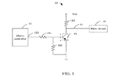
- the drawing is a schematic circuit diagram of one embodiment of mute drive circuit in accordance with the present disclosure.
- the mute circuit 10 can be applied in multimedia electronic devices, such as MP3 and mobile phones.
- the mute drive circuit 10 includes a micro-controller 12, a switch such as an npn transistor 14, a mute circuit 16, a first voltage-dividing resistance 181, a second voltage-dividing resistance 182, and a current-limiting resistance 183.
- the micro-controller 12 includes an I/O port 122.
- the I/O port 22 is a GPRO port.
- Vcc system voltage
- the I/O port 22 is set to a logic low.
- the I/O port 22 is controlled by the micro-controller 12 through software to be logic low for a period and then pulled up to a logic high.
- the I/O port 22 is controlled by the micro-controller 12 through software to be logic low.
- the system voltage Vcc is read as logic high and the I/O port 22 as logic low.
- the system voltage Vcc can be considered as logic high and the I/O port 22 is logic low when, for example, the voltage of the system voltage Vcc is above 0.7V.
- a base of the npn transistor 14 is connected with the I/O port 22 of the micro-controller 12 via the first voltage-dividing resistance 183, and is grounded via the second voltage-dividing resistance 181.
- An emitter of the npn transistor 14 is grounded.
- a connector of the npn transistor 14 is connected with the system voltage Vcc via the current-limiting resistance 183, and connected with the mute circuit 16 forming the control port O of the mute circuit 16.
- the npn transistor 14 When the I/O port 22 is pulled down to a logic low, the npn transistor 14 is turned off, which makes the control port O of the mute circuit 16 connect to the system voltage Vcc, that is to say, the control port O is set to the logic high.
- the npn transistor 14 When the I/O port 22 is pulled up to a logic high, the npn transistor 14 is turned on, which makes the control port O of the mute circuit 16 connect to ground, that is to say, the control port O is set to the logic low.
- the mute circuit 16 performs the mute mode when the control port O is set to a logic high, and performs the normal mode when the control port O is set to the logic low.
- the I/O port 122 When the electronic device using the mute circuit 10 is plugged into an AC power source , the I/O port 122 is pulled down to the logic low, that is to say, the control port O is set to the logic high, and the mute circuit 16 performs the mute mode.
- the I/O port 122 When the electronic device is turned on, the I/O port 122 is controlled by the micro-controller 12 to keep to be logic low for a period and then be pulled up to the logic high, that is to say, the control port O is set to the logic low for a period and then pulled up to the logic high, the mute circuit 16 performs the mute mode for a period and then enters into the normal mode.
- the I/O port 122 is controlled by the micro-controller12 to be logic low, that is to say, the control port O is set to the logic high, and the mute circuit 16 performs the mute mode.
- the system voltage Vcc is pulled up to the logic high
- the I/O port 122 is pulled down to the logic low, that is to say, the control port O is pulled down to the logic high
- the mute circuit 16 performs the mute mode.
- the mute drive circuit 10 uses hardware characteristics of the micro-controller, the system voltage VCC, and the I/O port to control the mute circuit 16 to perform the mute mode, thereby eliminating noise generated by plugging or unplugging into/out of the AC power source or implementing the turning on/off operation.
Landscapes
- Engineering & Computer Science (AREA)
- Power Engineering (AREA)
- Physics & Mathematics (AREA)
- Computer Hardware Design (AREA)
- Computing Systems (AREA)
- General Engineering & Computer Science (AREA)
- Mathematical Physics (AREA)
- Amplifiers (AREA)
- Circuit For Audible Band Transducer (AREA)
Abstract
A mute drive circuit (10) includes a micro-controller (12) including an I/O port (122); a mute circuit (16); and an npn transistor (14). When an electronic device using the mute circuit is plugged into an AC power source, the I/O port is set to the logic low, the mute circuit performs the mute mode. When the electronic device is turned on, the I/O port is controlled set to the logic low for a period and then be pulled up to the logic high, the mute circuit performs the mute mode for the period and then enters into the normal mode. When the electronic device is turned off, the I/O port is controlled to set to the logic low, the mute circuit performs the mute mode. When the electronic device is unplugged from the AC power source, the I/O port is pulled down to the logic low, the mute circuit performs the mute mode.
Description
- The present disclosure relates to mute drive circuits, and more particularly to a mute drive circuit for eliminating noise generated by plugging or unplugging into/out of an AC power source or implementing a turning on/off operation.
- Noise such as a popping sound and/or static is familiar to people during plugging in or out power supply and implementing turning on or off operation on multimedia electronic devices, such as MP3 and mobile phones. A method to eliminate or suppress such noise is using a tank circuit connected to the power supply for releasing energy when the power is suddenly decreased or increased, thereby a mute mode could be performed for a period to eliminate the POP noise. However, the tank circuit needs two transistors and an electrolytic capacitor, and so is costly.
- The components in the drawings are not necessarily drawn to scale, the emphasis instead being placed upon clearly illustrating the principles of the mute drive circuit for eliminating noise generated by plugging or unplugging into/out of an AC power source or implementing a turning on/off operation.
- The drawing is a schematic circuit diagram of one embodiment of mute drive circuit in accordance with the present disclosure.
- The disclosure is illustrated by way of example and not by way of limitation in the figures of the accompanying drawings in which like references indicate similar elements. It should be noted that references to "an" or "one" embodiment in this disclosure are not necessarily to the same embodiment, and such references mean at least one.
- The
mute circuit 10 can be applied in multimedia electronic devices, such as MP3 and mobile phones. Referring to the drawing, themute drive circuit 10 includes a micro-controller 12, a switch such as annpn transistor 14, amute circuit 16, a first voltage-dividingresistance 181, a second voltage-dividingresistance 182, and a current-limitingresistance 183. - The micro-controller 12 includes an I/
O port 122. The I/O port 22 is a GPRO port. When the electronic device using themute circuit 10 is plugged into an AC power source, a system voltage Vcc is connected and the I/O port 22 is set to a logic low. When the electronic device is turned on, the I/O port 22 is controlled by the micro-controller 12 through software to be logic low for a period and then pulled up to a logic high. When the electronic device is turned off, the I/O port 22 is controlled by the micro-controller 12 through software to be logic low. When the electronic device using themute circuit 10 is unplugged from the AC power source, as a decreasing rate of voltage of the I/O port 22 is faster than a decreasing rate of voltage of the system voltage Vcc, therefore the system voltage Vcc is read as logic high and the I/O port 22 as logic low. The system voltage Vcc can be considered as logic high and the I/O port 22 is logic low when, for example, the voltage of the system voltage Vcc is above 0.7V. - A base of the
npn transistor 14 is connected with the I/O port 22 of the micro-controller 12 via the first voltage-dividingresistance 183, and is grounded via the second voltage-dividingresistance 181. An emitter of thenpn transistor 14 is grounded. A connector of thenpn transistor 14 is connected with the system voltage Vcc via the current-limiting resistance 183, and connected with themute circuit 16 forming the control port O of themute circuit 16. - When the I/O port 22 is pulled down to a logic low, the
npn transistor 14 is turned off, which makes the control port O of themute circuit 16 connect to the system voltage Vcc, that is to say, the control port O is set to the logic high. When the I/O port 22 is pulled up to a logic high, thenpn transistor 14 is turned on, which makes the control port O of themute circuit 16 connect to ground, that is to say, the control port O is set to the logic low. - The
mute circuit 16 performs the mute mode when the control port O is set to a logic high, and performs the normal mode when the control port O is set to the logic low. - When the electronic device using the
mute circuit 10 is plugged into an AC power source , the I/O port 122 is pulled down to the logic low, that is to say, the control port O is set to the logic high, and themute circuit 16 performs the mute mode. When the electronic device is turned on, the I/O port 122 is controlled by the micro-controller 12 to keep to be logic low for a period and then be pulled up to the logic high, that is to say, the control port O is set to the logic low for a period and then pulled up to the logic high, themute circuit 16 performs the mute mode for a period and then enters into the normal mode. When the electronic device is turned off, the I/O port 122 is controlled by the micro-controller12 to be logic low, that is to say, the control port O is set to the logic high, and themute circuit 16 performs the mute mode. When the electronic device using themute circuit 10 is unplugged from the AC power source, the system voltage Vcc is pulled up to the logic high, and the I/O port 122 is pulled down to the logic low, that is to say, the control port O is pulled down to the logic high, themute circuit 16 performs the mute mode. - The
mute drive circuit 10 uses hardware characteristics of the micro-controller, the system voltage VCC, and the I/O port to control themute circuit 16 to perform the mute mode, thereby eliminating noise generated by plugging or unplugging into/out of the AC power source or implementing the turning on/off operation. - Although the current disclosure has been specifically described on the basis of the exemplary embodiment thereof, the disclosure is not to be construed as being limited thereto. Various changes or modifications may be made to the embodiment without departing from the scope and spirit of the disclosure.
Claims (5)
- A mute drive circuit comprising:a micro-controller comprising an I/O port;a mute circuit comprising a control port, performing a mute mode when the control port is pulled up to a logic high, and performing a normal mode when the control port is set to a logic low;a switch, being turned off when the I/O port is set to a logic high to make the control port of the mute circuit connect to a system voltage, thereby being pulled up to the logic high, being turned on when the I/O port is set to the logic low to make the control port of the mute circuit to connect to ground, thereby being set to the logic low;wherein when an electronic device using the mute circuit is plugged into an AC power source, the system voltage is connected, the I/O port is set to the logic low, the control port is set to the logic high, the mute circuit performs the mute mode, when the electronic device is turned on, the I/O port is controlled by the micro-controller to set to the logic low for a period and then be pulled up to the logic high, the control port is set to the logic low for the period and then pulled up to the logic high, the mute circuit performs the mute mode for the period and then enters into the normal mode, when the electronic device is turned off, the I/O port is controlled by the micro-controller to keep logic low, the control port is set to the logic high, the mute circuit performs the mute mode, when the electronic device is unplugged from the AC power source, the system voltage is pulled up to the logic high, and the I/O port is pulled down to the logic low, the control port is pulled down to the logic high, the mute circuit performs the mute mode.
- The mute drive circuit of claim 1, wherein the switch comprises a npn type transistor, a base of the npn transistor is connected with the I/O port via a first voltage-dividing resistance, and is grounded via a second voltage-dividing resistance, an emitter of the npn transistor is grounded, a connector of the npn transistor is connected with the system voltage via a current-limiting resistance, and is connected with the control port of the mute circuit.
- The mute drive circuit of claim 1, wherein the I/O port is a GPRO port.
- The mute drive circuit of claim 1, wherein when the electronic device is turned on, the I/O port is controlled by the micro-controller through software to set to the logic low for a period and then pulled up to the logic high, when the electronic device is turned off, the I/O port is controlled by the micro-controller through software to set to the logic low.
- The mute drive circuit of claim 1, wherein the system voltage is read as logic high and the I/O port as logic low when the voltage of the system voltage is above 0.7V.
Applications Claiming Priority (1)
| Application Number | Priority Date | Filing Date | Title |
|---|---|---|---|
| CN201210061565.1A CN103313169A (en) | 2012-03-09 | 2012-03-09 | Muting drive circuit |
Publications (1)
| Publication Number | Publication Date |
|---|---|
| EP2637307A1 true EP2637307A1 (en) | 2013-09-11 |
Family
ID=46084758
Family Applications (1)
| Application Number | Title | Priority Date | Filing Date |
|---|---|---|---|
| EP12161910.0A Withdrawn EP2637307A1 (en) | 2012-03-09 | 2012-03-28 | Mute drive circuit |
Country Status (5)
| Country | Link |
|---|---|
| US (1) | US20130236030A1 (en) |
| EP (1) | EP2637307A1 (en) |
| JP (1) | JP2013187902A (en) |
| CN (1) | CN103313169A (en) |
| TW (1) | TW201338572A (en) |
Families Citing this family (3)
| Publication number | Priority date | Publication date | Assignee | Title |
|---|---|---|---|---|
| CN107426648A (en) * | 2016-05-24 | 2017-12-01 | 华为技术有限公司 | A kind of mute circuit and electronic equipment |
| CN106686492B (en) * | 2017-01-22 | 2019-06-25 | 深圳市华星光电技术有限公司 | A kind of audio output circuit and audio frequency apparatus |
| CN110856079A (en) * | 2019-11-15 | 2020-02-28 | Tcl华星光电技术有限公司 | Audio system and method for eliminating noise at power-on moment |
Citations (2)
| Publication number | Priority date | Publication date | Assignee | Title |
|---|---|---|---|---|
| US5488258A (en) * | 1993-03-05 | 1996-01-30 | Pioneer Electric Corporation | Circuit for muting noises in a power amplifier |
| EP0862265A2 (en) * | 1997-02-26 | 1998-09-02 | THOMSON multimedia | Anti pop for power off |
Family Cites Families (1)
| Publication number | Priority date | Publication date | Assignee | Title |
|---|---|---|---|---|
| CN103313168A (en) * | 2012-03-08 | 2013-09-18 | 鸿富锦精密工业(深圳)有限公司 | Headset jack drive circuit |
-
2012
- 2012-03-09 CN CN201210061565.1A patent/CN103313169A/en active Pending
- 2012-03-15 TW TW101108780A patent/TW201338572A/en unknown
- 2012-03-27 US US13/430,701 patent/US20130236030A1/en not_active Abandoned
- 2012-03-28 EP EP12161910.0A patent/EP2637307A1/en not_active Withdrawn
-
2013
- 2013-02-20 JP JP2013030699A patent/JP2013187902A/en active Pending
Patent Citations (2)
| Publication number | Priority date | Publication date | Assignee | Title |
|---|---|---|---|---|
| US5488258A (en) * | 1993-03-05 | 1996-01-30 | Pioneer Electric Corporation | Circuit for muting noises in a power amplifier |
| EP0862265A2 (en) * | 1997-02-26 | 1998-09-02 | THOMSON multimedia | Anti pop for power off |
Non-Patent Citations (1)
| Title |
|---|
| "Taschenbuch der Elektrotechnik und Elektronik passage", 31 December 1993, FACHBUCHVERLAG LEIPZIG-KÖLN, Leibzig, ISBN: 3-343-00847-8, article HELMUT LINDNER ET AL: "Taschenbuch der Elektrotechnik und Elektronik passage", pages: 320 - 323, XP055067730 * |
Also Published As
| Publication number | Publication date |
|---|---|
| CN103313169A (en) | 2013-09-18 |
| TW201338572A (en) | 2013-09-16 |
| JP2013187902A (en) | 2013-09-19 |
| US20130236030A1 (en) | 2013-09-12 |
Similar Documents
| Publication | Publication Date | Title |
|---|---|---|
| US8831241B2 (en) | Earphone jack drive circuit | |
| CN103810958A (en) | Driving circuit, working method of driving circuit and display device | |
| CN102202117A (en) | Electronic device with USB (universal serial bus) interface and USB communication starting method thereof | |
| CN103034608B (en) | Plug-and-play circuit, interface circuit and electronic equipment assembly | |
| US20200244241A1 (en) | Mute control circuit used upon power-on or power-of, control method, and audio device | |
| CN105845068B (en) | A kind of power supply circuit of source drive module, display panel and display device | |
| US8757985B2 (en) | Fan control circuit | |
| CN204012687U (en) | There is the protective circuit of the pooling feature that powers on | |
| US9791916B2 (en) | Control circuit including load switch, electronic apparatus including the load switch, and control method thereof | |
| US20130236030A1 (en) | Mute drive circuit | |
| WO2012134586A1 (en) | Automatic volume reduction | |
| US8939730B2 (en) | Fan control system | |
| CN108319186B (en) | Overcurrent protection device and method for USB equipment | |
| US10389228B1 (en) | Power supply circuit with surge-supression | |
| CN104810868B (en) | Charging system and charging method thereof | |
| US20160170457A1 (en) | Power control circuit and electronic device | |
| CN101527543B (en) | Audio system capable of suppressing switching noise and its audio amplifier | |
| CN104300946A (en) | Quick power-down module of low-voltage equipment | |
| US20120267958A1 (en) | Current suppression circuit and electronic device employing the same | |
| US8622711B2 (en) | Fan control circuit | |
| US9866015B2 (en) | Discharge circuit and motherboard utilizing the same | |
| CN107817699B (en) | Control circuit, control method and electronic device | |
| CN203661276U (en) | Mute control circuit | |
| CN223599490U (en) | DC power input overvoltage protection circuit and electronic equipment | |
| CN106711959B (en) | Control circuits and electronic equipment |
Legal Events
| Date | Code | Title | Description |
|---|---|---|---|
| PUAI | Public reference made under article 153(3) epc to a published international application that has entered the european phase |
Free format text: ORIGINAL CODE: 0009012 |
|
| AK | Designated contracting states |
Kind code of ref document: A1 Designated state(s): AL AT BE BG CH CY CZ DE DK EE ES FI FR GB GR HR HU IE IS IT LI LT LU LV MC MK MT NL NO PL PT RO RS SE SI SK SM TR |
|
| AX | Request for extension of the european patent |
Extension state: BA ME |
|
| STAA | Information on the status of an ep patent application or granted ep patent |
Free format text: STATUS: THE APPLICATION IS DEEMED TO BE WITHDRAWN |
|
| 18D | Application deemed to be withdrawn |
Effective date: 20140312 |