EP2637259A1 - Control device - Google Patents
Control device Download PDFInfo
- Publication number
- EP2637259A1 EP2637259A1 EP11837796.9A EP11837796A EP2637259A1 EP 2637259 A1 EP2637259 A1 EP 2637259A1 EP 11837796 A EP11837796 A EP 11837796A EP 2637259 A1 EP2637259 A1 EP 2637259A1
- Authority
- EP
- European Patent Office
- Prior art keywords
- openable
- closable door
- holding
- control apparatus
- holding members
- Prior art date
- Legal status (The legal status is an assumption and is not a legal conclusion. Google has not performed a legal analysis and makes no representation as to the accuracy of the status listed.)
- Withdrawn
Links
Images







Classifications
-
- H—ELECTRICITY
- H01—ELECTRIC ELEMENTS
- H01R—ELECTRICALLY-CONDUCTIVE CONNECTIONS; STRUCTURAL ASSOCIATIONS OF A PLURALITY OF MUTUALLY-INSULATED ELECTRICAL CONNECTING ELEMENTS; COUPLING DEVICES; CURRENT COLLECTORS
- H01R13/00—Details of coupling devices of the kinds covered by groups H01R12/70 or H01R24/00 - H01R33/00
- H01R13/46—Bases; Cases
- H01R13/52—Dustproof, splashproof, drip-proof, waterproof, or flameproof cases
- H01R13/5213—Covers
-
- G—PHYSICS
- G06—COMPUTING OR CALCULATING; COUNTING
- G06F—ELECTRIC DIGITAL DATA PROCESSING
- G06F1/00—Details not covered by groups G06F3/00 - G06F13/00 and G06F21/00
- G06F1/16—Constructional details or arrangements
-
- G—PHYSICS
- G06—COMPUTING OR CALCULATING; COUNTING
- G06F—ELECTRIC DIGITAL DATA PROCESSING
- G06F1/00—Details not covered by groups G06F3/00 - G06F13/00 and G06F21/00
- G06F1/16—Constructional details or arrangements
- G06F1/1601—Constructional details related to the housing of computer displays, e.g. of CRT monitors, of flat displays
-
- G—PHYSICS
- G06—COMPUTING OR CALCULATING; COUNTING
- G06K—GRAPHICAL DATA READING; PRESENTATION OF DATA; RECORD CARRIERS; HANDLING RECORD CARRIERS
- G06K19/00—Record carriers for use with machines and with at least a part designed to carry digital markings
- G06K19/06—Record carriers for use with machines and with at least a part designed to carry digital markings characterised by the kind of the digital marking, e.g. shape, nature, code
- G06K19/067—Record carriers with conductive marks, printed circuits or semiconductor circuit elements, e.g. credit or identity cards also with resonating or responding marks without active components
- G06K19/07—Record carriers with conductive marks, printed circuits or semiconductor circuit elements, e.g. credit or identity cards also with resonating or responding marks without active components with integrated circuit chips
- G06K19/077—Constructional details, e.g. mounting of circuits in the carrier
- G06K19/0772—Physical layout of the record carrier
- G06K19/07732—Physical layout of the record carrier the record carrier having a housing or construction similar to well-known portable memory devices, such as SD cards, USB or memory sticks
-
- H—ELECTRICITY
- H01—ELECTRIC ELEMENTS
- H01R—ELECTRICALLY-CONDUCTIVE CONNECTIONS; STRUCTURAL ASSOCIATIONS OF A PLURALITY OF MUTUALLY-INSULATED ELECTRICAL CONNECTING ELEMENTS; COUPLING DEVICES; CURRENT COLLECTORS
- H01R13/00—Details of coupling devices of the kinds covered by groups H01R12/70 or H01R24/00 - H01R33/00
- H01R13/62—Means for facilitating engagement or disengagement of coupling parts or for holding them in engagement
- H01R13/639—Additional means for holding or locking coupling parts together, after engagement, e.g. separate keylock, retainer strap
-
- H—ELECTRICITY
- H01—ELECTRIC ELEMENTS
- H01R—ELECTRICALLY-CONDUCTIVE CONNECTIONS; STRUCTURAL ASSOCIATIONS OF A PLURALITY OF MUTUALLY-INSULATED ELECTRICAL CONNECTING ELEMENTS; COUPLING DEVICES; CURRENT COLLECTORS
- H01R13/00—Details of coupling devices of the kinds covered by groups H01R12/70 or H01R24/00 - H01R33/00
- H01R13/62—Means for facilitating engagement or disengagement of coupling parts or for holding them in engagement
- H01R13/639—Additional means for holding or locking coupling parts together, after engagement, e.g. separate keylock, retainer strap
- H01R13/6395—Additional means for holding or locking coupling parts together, after engagement, e.g. separate keylock, retainer strap for wall or panel outlets
-
- H—ELECTRICITY
- H05—ELECTRIC TECHNIQUES NOT OTHERWISE PROVIDED FOR
- H05K—PRINTED CIRCUITS; CASINGS OR CONSTRUCTIONAL DETAILS OF ELECTRIC APPARATUS; MANUFACTURE OF ASSEMBLAGES OF ELECTRICAL COMPONENTS
- H05K5/00—Casings, cabinets or drawers for electric apparatus
- H05K5/02—Details
- H05K5/0256—Details of interchangeable modules or receptacles therefor, e.g. cartridge mechanisms
- H05K5/0286—Receptacles therefor, e.g. card slots, module sockets, card groundings
-
- H—ELECTRICITY
- H05—ELECTRIC TECHNIQUES NOT OTHERWISE PROVIDED FOR
- H05K—PRINTED CIRCUITS; CASINGS OR CONSTRUCTIONAL DETAILS OF ELECTRIC APPARATUS; MANUFACTURE OF ASSEMBLAGES OF ELECTRICAL COMPONENTS
- H05K5/00—Casings, cabinets or drawers for electric apparatus
- H05K5/02—Details
- H05K5/03—Covers
-
- H—ELECTRICITY
- H05—ELECTRIC TECHNIQUES NOT OTHERWISE PROVIDED FOR
- H05K—PRINTED CIRCUITS; CASINGS OR CONSTRUCTIONAL DETAILS OF ELECTRIC APPARATUS; MANUFACTURE OF ASSEMBLAGES OF ELECTRICAL COMPONENTS
- H05K7/00—Constructional details common to different types of electric apparatus
- H05K7/14—Mounting supporting structure in casing or on frame or rack
- H05K7/1462—Mounting supporting structure in casing or on frame or rack for programmable logic controllers [PLC] for automation or industrial process control
- H05K7/1481—User interface, e.g. status displays; Programming interface, e.g. connector for computer programming; Monitoring
-
- G—PHYSICS
- G06—COMPUTING OR CALCULATING; COUNTING
- G06F—ELECTRIC DIGITAL DATA PROCESSING
- G06F2212/00—Indexing scheme relating to accessing, addressing or allocation within memory systems or architectures
- G06F2212/21—Employing a record carrier using a specific recording technology
- G06F2212/214—Solid state disk
- G06F2212/2146—Solid state disk being detachable, e.g.. USB memory
-
- G—PHYSICS
- G06—COMPUTING OR CALCULATING; COUNTING
- G06F—ELECTRIC DIGITAL DATA PROCESSING
- G06F2213/00—Indexing scheme relating to interconnection of, or transfer of information or other signals between, memories, input/output devices or central processing units
- G06F2213/0042—Universal serial bus [USB]
Definitions
- the present invention relates to a control apparatus to which a USB device is connectable and from which the USB device is disconnectable.
- USB Universal Serial Bus
- USB device Some control apparatuses are known to receive a USB (Universal Serial Bus) device and transmit data to and from the USB device.
- USB Universal Serial Bus
- a wide variety of devices are available as the USB device.
- the USB device When in use, in some cases the USB device is in connection for a comparatively short period of time, being connected and disconnected frequently, while in other cases the USB device is in connection for a comparatively long period of time.
- a USB memory which is a kind of USB device, generally has a comparatively short connection time, being connected and disconnected every time the intended work is done.
- the USB memory needs to be held in connected state for a long period of time.
- the above-described conventional art has the following problems.
- the conventional art recited in Japanese Unexamined Patent Application Publication No. 2006-294260 requires that the USB memory have a shape corresponding to the control apparatus side.
- this conventional art lacks versatility, being unable to accommodate to a wide variety of USB memories.
- the USB memory is only inserted into the connector under pressure, instead of being turned into held state. Thus, resistance against vibration, shock, and other kinds of impact is insufficient.
- a control apparatus to which a USB device is connectable and from which the USB device is disconnectable includes a port, an openable and closable door, and a holding mechanism.
- a port Into the port, a connector of the USB device is insertable.
- the openable and closable door is disposed adjacent the port, and configured to open so as to expose the port and configured to close so as to shield the port.
- the holding mechanism is disposed at the openable and closable door and configured to hold a housing of the USB device when the openable and closable door is open.
- USB devices With the present invention, a wide variety of USB devices are held in connected state with high holding strength.
- a control apparatus 1 is a control apparatus that controls a control object, not shown.
- the control apparatus 1 include Factory Automation (FA) machines such as a Programmable Logic Controller (PLC).
- FA Factory Automation
- PLC Programmable Logic Controller
- USB Universal Serial Bus
- a USB memory 50 which is a kind of USB device, will be exemplified to be connected to the control apparatus 1.
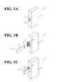
- a port 3 is disposed on one surface of a housing 2 of the control apparatus 1 (on the left lower side as seen in FIGs. 1A to 1C ).
- the port 3 accepts a connector 51 of the USB memory 50.
- the side on which the port 3 is disposed will be referred to as the front side of the control apparatus 1.
- Adjacent the front side of the port 3, an openable and closable door 4 is disposed in an openable and closable manner with one side having a hinge structure. When the openable and closable door 4 is open, the openable and closable door 4 exposes the port 3 as shown in FIG.
- the openable and closable door 4 shields the port 3 as shown in FIG. 1A .
- USB ports implemented on Office Automation (OA) machines such as personal computers are exposed. Particularly in environments where FA machines are installed, this leaves a possibility of attachment of dust, oil mist, and other substances to the port, causing electrical short-circuit, communication disturbance, and other occurrences.
- the control apparatus 1 is provided with the openable and closable door 4.
- the openable and closable door 4 includes a holding mechanism 100 to hold a housing 52 of the USB memory 50 when the openable and closable door 4 is open.
- the holding mechanism 100 includes a regulation member 120 to regulate movement of slide plates 101, described later, on the outer surface of the openable and closable door 4.
- the holding mechanism 100 includes two slide plates 101 to hold the housing 52 of the USB memory 50 on both sides of the housing 52 so as to support the housing 52.
- the two slide plates 101 are disposed at one side and the other side (upper side and lower side in the example shown in FIGs. 2A and 2B ) of the inner surface of the openable and closable door 4.
- the slide plates 101 are movable in directions in which they come close to and apart from one another (in the vertical directions in FIGs. 2A and 2B ).
- the slide plates 101 are examples of the holding members recited in the appended claims.
- each of the slide plates 101 is secured at one end of a corresponding support 102.
- the support 102 is in slidable contact with a guide 103, which is secured to the inner surface of the openable and closable door 4.
- a rack gear 104 is disposed on the other end side of the support 102.
- the rack gear 104 meshes with a gear member 121 (see FIGs. 3A to 3C ), which is integral with the regulation member 120 across the openable and closable door 4.
- a slide-side spring fixing portion 105 is disposed.
- a spring 107 is disposed between the slide-side spring fixing portion 105 and a door-side spring fixing portion 106, which is disposed at the inner surface of the openable and closable door 4.
- the spring 107 at any time biases the corresponding slide plate 101 to return to its reference position (the position shown in FIGs. 2A and 2B ).
- the spring 107 is an example of the first biasing means recited in the appended claims.
- the reference positions of the respective slide plates 101 are predetermined at appropriate positions so that the slide plates 101 are within the area of the inner surface of the openable and closable door 4. This enables the openable and closable door 4 to open and close with the slide plates 101 positioned at their respective reference positions.
- the port 3 is disposed at a further inward position than the surfaces of the housing 2, so that when the openable and closable door 4 is closed, the holding mechanism 100 including the slide plates 101 (but excluding the regulation member 120) is accommodated within the space defined by the inner surface of the openable and closable door 4 and the port 3.
- Each of the slide plates 101 includes an elastic member 108 at a portion in contact with the housing 52 of the USB memory 50.
- the elastic member 108 is made of rubber, elastomer, or similar material.
- the elastic member 108 eliminates or minimizes slipping of the slide plate 101 and the housing 52.
- the housing 52 of the USB memory 50 has a shape that comes into contact with the slide plates 101 in a parallel manner. Even if the housing has a shape that is, for example, inclined relative to the slide plates 101 or has depressions and protrusions, the elastic members 108 can be elastically deformed to reliably hold the housing between the elastic members 108.
- the elastic members 108 are capable of holding between them USB devices of a wide variety of shapes, providing improved versatility.
- a presser plate 109 is disposed as if to cover the gear member 121 from behind (from the right side in FIG. 2A and from the front side of the paper surface of FIG. 2B ). Between the presser plate 109 and the gear member 121, a presser spring 110 is disposed. The presser spring 110 at any time biases the integrated regulation member 120 and gear member 121 toward the outer surface of the openable and closable door 4.
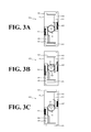
- FIGs. 3A to 3C a relationship between the handling of the regulation member 120 and the operation of the slide plates 101 will be described. It is noted that in FIG. 3 , the presser plate 109 and the presser spring 110 are not shown for ease of description.
- FIG. 3A illustrates a state in which the slide plates 101 are positioned at their respective reference positions.
- the gear member 121 rotates in the clockwise direction (with the openable and closable door 4 seen from inside), as represented by the arrow A1 shown in FIG. 3B .
- This brings the supports 102 into sliding movement along the guides 103 against the compressive force of the springs 107 as shown in FIG. 3B . That is, the slide plates 101 move in directions in which the slide plates 101 come close to one another, thereby diminishing the distance between the slide plates 101.
- the slide plates 101 are operable over a wide area that exceeds the area of the inner surface of the openable and closable door 4. This is because the holding mechanism 100 is disposed at the openable and closable door 4, and opening the openable and closable door 4 causes the holding mechanism 100 to move to outside of the control apparatus 1, which eliminates any restrictions on the operation of the slide plates 101 associated with the housing shape of the control apparatus 1 or other factors.
- a holding mechanism of a similar structure is disposed in a depression of the housing dedicated to the port.
- the operable range of the slide plates is limited to the size of the depression.
- this embodiment greatly enlarges the operable range of the slide plates 101, which is significantly advantageous. This, as a result, ensures holding of USB devices of a wide variety of sizes and shapes, and provides improved versatility.
- the brake function stops the slide plates 101 at this holding position against the biasing force of the springs 107, which at any time bias the slide plates 101 to return to their respective reference positions, as described above. It is noted that in FIG. 5 , the presser plate 109, the presser spring 110, and the gear member 121 are not shown for ease of description.
- the gear member 121 includes a gear 122, a trunk 123, and an axis 124.
- the gear 122 has, on its outer circumference, teeth to mesh with the rack gear 104.
- the trunk 123 couples the gear 122 and the regulation member 120 to one another while ensuring a predetermined distance therebetween.
- the gear 122 and the trunk 123 are coaxial to the axis 124.
- the axis 124 of the gear member 121 is inserted into the regulation member 120, and thus the regulation member 120 and the gear member 121 are coupled to one another into an integral configuration.
- a hemispheric protrusion 126 is formed on an end surface 125 of the gear 122 on the side of the regulation member 120. While in this embodiment the gear 122, the trunk 123, and the axis 124 of the gear member 121 are integrally formed as shown in FIG. 6 , they may be formed as separate elements coupled to each other.
- the openable and closable door 4 includes a through hole 127 to penetrate through the trunk 123 of the gear member 121.
- the through hole 127 has an inner diameter approximately equal to the outer diameter of the trunk 123 of the gear member 121.
- the circumferential portion of the through hole 127 in the radial direction is thinner in thickness than the other portions of the openable and closable door 4.
- the thinner portion functions as a bearing 128 to slidably support the trunk 123 of the gear member 121 in such a manner that the trunk 123 can make rotational and linear motions.
- the round holes 130 are capable of engaging with the protrusion 126 of the gear member 121.
- the round holes 130 are arranged circumferentially at a predetermined pitch.
- the integrated regulation member 120 and gear member 121 are at any time biased by the presser spring 110 toward the outer surface of the openable and closable door 4 (the left side in FIG. 6 ).
- This brings the end surface 125 of the gear member 121 into contact with the end surface 129 of the bearing 128, thereby bringing the protrusion 126 into engagement with one of the round holes 130.
- the engagement of the protrusion 126 restricts the rotation of the gear member 121, and this in turn restricts the movement of the supports 102, which mesh with the gear 122 of the gear member 121 at the rack gears 104. In this manner, brake acts on the slide plates 101.
- the protrusion 126 of the gear member 121 moves over the end surface 129 while straddling the round holes 130. That is, the regulation member 120 is handled into rotation by a handling force greater than the friction force acting between the protrusion 126 and the round holes 130.
- the pitch between the round holes 130 is set at a small level to prevent the protrusion 126 from becoming stuck between adjoin round holes 130. This ensures that when the regulation member 120 is in non-handled state, the protrusion 126 of the gear member 121 is engaged with any one of the round holes 130.
- brake keeps acting on the slide plates 101 unless a release operation of the brake is performed, described later.
- the minimum movement of the slide plates 101 is equivalent to the pitch between the circumferentially formed round holes 130.
- the elastic members 108 are disposed on the slide plates 101, as described above. The elastic members 108 are elastically deformed and make the dimensional error tolerable, and come into contact with the housing 52 at the slide plates 101, thereby reliably holding the housing 52 between the elastic members 108.
- the presser spring 110, the protrusion 126, the round holes 130, the gear 122, and the rack gear 104 are examples of the position fixing means recited in the appended claims.
- FIG. 8A illustrates a state in which brake is in action
- FIG. 8B illustrates a state in which brake is released.
- the rack gear 104 is disposed at the other side (the lower side in FIG. 7 ) of the support 102 opposite its one end (the upper end in FIG. 7 ) to which the slide plate 101 and the elastic member 108 are secured.
- the rack gear 104 is not disposed over the entire thickness of the support 102 (which is in the lateral direction in FIG. 7 ). Instead, the rack gear 104 is disposed over approximately half the thickness of the support 102. The other half is a toothless, flat portion 131.
- the presser spring 110 biases the gear member 121 toward the outer surface of the openable and closable door 4 (the left side in FIG. 8 ), keeping the protrusion 126 of the gear member 121 in engagement with one of the round holes 130 of the openable and closable door 4.
- the engagement of the protrusion 126 restricts the rotation of the gear member 121, and this in turn restricts the movement of the supports 102, which mesh with the gear 122 of the gear member 121 at the rack gears 104. In this manner, brake is acting on the slide plates 101.
- This kind of brake release is done when, for example, the housing 52 of the USB memory 50 to be removed has a smaller width than the reference width of the slide plates 101 (see FIGs. 10A to 10C , described later). Instead of releasing the brake, it is also possible to remove such USB memory 50 by handling the regulation member 120 into clockwise rotation and thereby enlarging the distance between the slide plates 101.
- the openable and closable door 4 includes an accepting space 132 at the bearing 128 on the outer surface side of the door (the left side in FIGs. 8A and 8B ).
- the accepting space 132 ensures pushing of the regulation member 120.
- an opening 133 is disposed to accept the axis 124 of the gear member 121 when the regulation member 120 is pushed inwardly.
- the regulation member 120, the accepting space 132, and the flat portion 131 are examples of the fixation releasing means recited in the appended claims.
- this embodiment provides a plated portion 5, which is subjected to plating treatment, as if to surround the port 3 as shown in FIG. 9A (where the area of the plated portion 5 is shaded).
- This embodiment also provides a plated portion 6, which is subjected to plating treatment over approximately the entire inner surface of the openable and closable door 4 as shown in FIG. 9B (where the area of the plated portion 6 is shaded).
- Examples of the plating material to be used include a conductive material such as copper and nickel.
- the plated portions 5 and 6 are both grounded to a frame ground (not shown) of the housing 2. It is noted that the holding mechanism 100 made up of the slide plates 101 and other elements is disposed on the plated portion 6 at the inner surface of the openable and closable door 4.
- the distance between the elastic members 108 when the slide plates 101 are positioned at the above-described reference positions will be referred to as a "reference width”.
- the operator handles the regulation member 120 into rotation in the anti-clockwise direction as represented by the arrow A3 shown in FIG. 10B .
- this brings the gear member 121 into rotation in the clockwise direction (with the openable and closable door 4 seen from inside).
- This brings the supports 102 into sliding movement along the guides 103 against the compressive force of the springs 107. That is, the slide plates 101 move in directions in which the slide plates 101 come close to one another.
- the housing 52 of the USB memory 50 is held between the slide plates 101, as shown in FIG. 10C .
- the USB memory 50 is connected, and this connected state is maintained with high holding strength.
- the operator may handle the regulation member 120 into rotation in the clockwise direction, which is opposite the above-described direction, thereby separating the slide plates 101 from one another. More simply, it is possible to inwardly push the regulation member 120. This releases the brake on the slide plates 101 as described above, and the slide plates 101 automatically return to their respective reference positions. Then, the connector 51 of the USB memory 50 is pulled out of the port 3, and thus the USB memory 50 is removed from the control apparatus 1.
- the operator handles the regulation member 120 into rotation in the anti-clockwise direction as represented by the arrow A5.
- this brings the gear member 121 into rotation in the clockwise direction (with the openable and closable door 4 seen from inside).
- This brings the supports 102 into sliding movement along the guides 103 against the compressive force of the springs 107. That is, the slide plates 101 move in directions in which the slide plates 101 come close to one another.
- the operator handles the regulation member 120 into rotation in the clockwise direction, which is opposite the above-described direction, thereby separating the slide plates 101 from one another. Then, the connector 51 of the USB memory 50 is pulled out of the port 3, and thus the USB memory 50 is removed from the control apparatus 1. It is noted that in this state the slide plates 101 protrude beyond the openable and closable door 4 as shown in FIG. 11C , making it impossible to close the openable and closable door 4. However, inwardly pushing the regulation member 120 makes the slide plates 101 automatically return to their respective reference positions, after which the openable and closable door 4 can be closed.
- the openable and closable door 4 Adjacent the port 3 of the control apparatus 1, the openable and closable door 4 is disposed. During the period of disconnection time of the USB memory 50, the openable and closable door 4 is closed to shield the port 3, while during the period of connection time of the USB memory 50, the openable and closable door 4 is open to expose the port 3.
- the holding mechanism 100 is disposed.
- the holding mechanism 100 holds the housing 52 of the connected USB memory 50, and this eliminates or minimizes pulling of the connector 51 of the USB memory 50 out of the port 3 and maintains the connection state of the USB memory 50 with high holding strength. Since the holding mechanism 100 is disposed at the openable and closable door 4, when the openable and closable door 4 opens, the holding mechanism 100 moves to outside of the housing 2 of the control apparatus 1. This ensures a structure that eliminates any restrictions on the holding operation of the holding mechanism 100 associated with the housing shape of the control apparatus 1 or other factors. This ensures holding of the housing 52 of the USB memory 50 even when it comes in a wide variety of sizes and shapes, and provides improved versatility.
- the openable and closable door 4 is closed to shield the port 3. This eliminates or minimizes electrical short-circuit of the port 3 and attachment, to the port 3, of dust and other substances that can cause communication disturbance or other occurrences.
- the holding mechanism 100 includes, at the inner surface of the openable and closable door 4, the two slide plates 101 to hold the housing 52 of the USB memory 50 between the slide plates 101.
- the slide plates 101 are movable in directions in which the slide plates 101, which are disposed on one side and the other side of the openable and closable door 4, come close to and apart from one another. This ensures that when the housing 52 of the USB memory 50 to be connected has a large width, the slide plates 101 move apart from one another to enlarge the distance between the slide plates 101, which permits the slide plates 101 to hold such housing 52 between the slide plates 101.
- the slide plates 101 move close to one another to diminish the distance between the slide plates 101, which permits the slide plates 101 to hold such housing 52 between the slide plates 101. In this manner, the housing 52 of the USB memory 50 is held even when it comes in a wide variety of sizes and shapes, which provides improved versatility. Additionally, the slide plates 101 are disposed at the inner surface of the openable and closable door 4. This ensures that closing the openable and closable door 4 during the period of disconnection time of the USB memory 50 eliminates or minimizes exposure of the slide plates 101 to the outside. This in turn eliminates or minimizes a disfigured external appearance of the control apparatus 1.
- the holding mechanism 100 includes, at the outer surface of the openable and closable door 4, the regulation member 120 to regulate movement of the slide plates 101 in directions in which the slide plates 101 come close to and apart from one another.
- the regulation member 120 With the use of the regulation member 120, the operator can easily move the slide plates 101. This improves operability associated with connection and disconnection of the USB memory 50.
- the distance between the slide plates 101 is adjusted while the slide plates 101 are moving in directions in which they come close to or apart from one another. Then at holding positions corresponding to the size of the housing 52 of the USB memory 50, the slide plates 101 hold the housing 52 between the slide plates 101 so as to support the housing 52.
- the brake function implemented by the engagement of the protrusion 126 of the gear member 121 with one of the round holes 130 of the openable and closable door 4 fixes the positions of the slide plates 101 at their respective holding positions. This eliminates or minimizes displacement of the slide plates 101 off the holding positions due to, for example, vibration, shock, and other kinds of impact, resulting in improved holding function of the USB memory 50. Even though the slide plates 101 are at any time biased by the springs 107 to return to the reference positions, the brake function keeps the slide plates 101 at the holding positions.
- the slide plates 101 each include the elastic member 108 at the portion of contact with the housing 52 of the USB memory 50. This eliminates or minimizes slipping between the slide plates 101 and the housing 52, and the holding function for the USB memory 50 further improves. Even if the housing 52 of the USB memory 50 has a shape that is, for example, inclined relative to the slide plates 101 or has depressions and protrusions, the elastic members 108 can be elastically deformed to reliably hold the housing 52 between the elastic members 108. Thus, the elastic members 108 are capable of holding between them the housing 52 of the USB memory 50 even if it comes in a wide variety of shapes, providing improved versatility. Further in this embodiment, the slide plates 101 move stepwise on the basis of the pitch between the round holes 130.
- the elastic members 108 which are disposed on the slide plates 101, are elastically deformed upon contact with the housing 52 and make the dimensional error tolerable.
- the elastic members 108 reliably hold the housing 52 between the elastic members 108.
- the inner surface of the openable and closable door 4 is plated with a conductive material. This eliminates or minimizes malfunction of the control apparatus 1 caused by, when the openable and closable door 4 is in closed state during the period of disconnection time of the USB memory 50, the port 3 becoming a source of emitting noise to outside the control apparatus 1 or becoming a source of receiving noise. Also, a certain area around the port 3 is plated, and this eliminates or minimizes the above-described noise emission and reception also when the USB memory 50 is in connection state with the openable and closable door 4 open.
- the second embodiment is similar to the first embodiment described above in maintaining the connected state of the housing 52 of the connected USB memory 50 with high holding strength by holding the housing 52.
- the second embodiment is different from the first embodiment in the configuration of the holding mechanism.
- a port 13 is disposed on one surface of a housing 12 of a control apparatus 11 (on the left lower side as seen in FIGs. 12A to 12C ).
- the port 13 accepts the connector 51 of the USB memory 50.
- the side on which the port 13 is disposed will be referred to as the front side of the control apparatus 11.
- the openable and closable door 14 When the openable and closable door 14 is open, the openable and closable door 14 exposes the port 13 as shown in FIG. 12B , while when closed, the openable and closable door 14 shields the port 13 as shown in FIG. 12A .
- the openable and closable door 14 includes a holding mechanism 200 to hold the housing 52 of the USB memory 50 when the openable and closable door 14 is open.
- the holding mechanism 200 includes a push button 220 to regulate movement of holding members 201 on the outer surface of the openable and closable door 14.
- the holding mechanism 200 includes two holding members 201 to hold the housing 52 of the USB memory 50 on both sides of the housing 52 so as to support the housing 52.
- the two holding members 201 are disposed at one side and the other side (upper side and lower side in this example) of the inner surface of the openable and closable door 14.
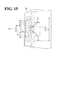
- the holding members 201 are movable in directions in which the holding members 201 come close to and apart from one another (in the vertical directions in FIG. 15 ).
- each of the holding members 201 is disposed at the distal end of a corresponding one of arm members 202.
- Each of the arm members 202 is curved in an approximately dogleg shape so as to avoid contact with the comers of the housing 52 when the holding members 201 hold the housing 52 of the USB memory 50 between the holding members 201.
- Each of the arm members 202 is rotatable about a corresponding one of axes 203 disposed at the upper side and the lower side of the inner surface of the openable and closable door 14.
- Each of the axes 203 is disposed at the openable and closable door 14 through axis supports 204 each having a larger diameter than the diameter of the corresponding axis 203. In this embodiment, as shown in FIGs.
- the openable and closable door 14 includes side walls 14a and 14b defining an approximate U-shape in plan view.
- Each of the axes 203 has its both ends supported by the side walls 14a and 14b through the axis supports 204.
- each of the axes 203 includes a torsion coil spring 205 having one end secured to the corresponding arm member 202 and another end secured to the corresponding axis 203.
- the torsion coil spring 205 at any time biases the arm member 202 into rotation in a direction in which the holding members 201 come close to one another (in the arrow X direction in FIG. 15 ).
- the biasing force of the coil springs 205 keeps the arm members 202 and the holding members 201 within the openable and closable door 14 (within the space between the side walls 14a and 14b) as shown in FIGs. 13A and 13B and FIGs. 14A to 14C .
- the torsion coil spring 205 is an example of the second biasing means recited in the appended claims. In FIGs. 14A to 14C , the torsion coil spring 205 is not shown.
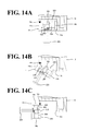
- FIGs. 14A to 14C each illustrate an open-close operation of the openable and closable door 14.
- the openable and closable door 14 is rotatable relative to the housing 12 about an axis 14c, which is a rotation axis disposed on the rear side of the side wall 14a (on the upper side in FIGs. 14A to 14C ).
- axis 14c which is a rotation axis disposed on the rear side of the side wall 14a (on the upper side in FIGs. 14A to 14C ).
- the openable and closable door 14 when the openable and closable door 14 is in closed state, the openable and closable door 14 as a whole, including the side walls 14a and 14b, is accommodated within a depression 12a of the housing 12 together with the holding mechanism 200.
- the openable and closable door 14 can be turned into rotation as shown in FIG. 14B .
- the openable and closable door 14 When the openable and closable door 14 is rotated approximately 90 degrees about the axis 14c as shown in FIG. 14C , the openable and closable door 14 is in open state and the port 13 is exposed. As shown in FIG. 14C , during the time when the openable and closable door 14 is open, the side wall 14b functions as a cover over the front side of the holding mechanism 200. This provides protection for the holding mechanism 200, eliminating or minimizing contact of the USB memory 50 and the operator's fingers with the holding mechanism 200. This also eliminates or minimizes a disfigured external appearance of the control apparatus 11 when the door is open.
- the push button 220 is disposed outside the openable and closable door 14 and coupled to a rectangular pushing plate 222 through an axis 221, which penetrates through the openable and closable door 14.
- the pushing plate 222 is disposed on the inner side of the openable and closable door 14.
- the ends of the pushing plate 222 in its longitudinal direction are in contact with respective protrusions 202a of the arm members 202, which are disposed at the upper side and the lower side of the openable and closable door 14. As shown in FIG.
- the axis 221 includes a coil spring 223 to at any time bias the push button 220 toward the side opposite the openable and closable door 14.
- the biasing force of the coil spring 223 returns the push button 220, the axis 221, and the pushing plate 222 to their respective pre-pushing positions.
- the biasing force of the torsion coil springs 205 brings the arm members 202 into rotation in a direction in which the holding members 201 come close to one another (in the arrow X direction in FIG. 15 ).
- the push button 220 is an example of the regulation member recited in the appended claims. In FIGs. 14A to 14C and 15 , the coil spring 223 is not shown.
- the holding mechanism 200 With the configuration of the holding mechanism 200 described above, handling (pushing and releasing) the push button 220 brings the arm members 202 into rotation in the Y direction and the X direction as shown in FIG. 15 .
- the holding members 201 move in directions in which the holding members 201 come close to and apart from one another while ensuring that the distance between the holding members 201 is in the range of G1 to G2.
- Each of the holding members 201 has an approximately cylindrical shape.
- the entire body of each holding member 201 is made of an elastic material such as rubber and elastomer.
- the holding members 201 have their outer circumference surfaces of the cylindrical shapes come into contact with the housing 52 of the USB memory 50. This ensures that the holding members 201 uniformly contact the housing 52 even if the holding members 201 change their angles by the rotation of the arm members 202.
- employing an elastic material for the entire body of each holding member 201 ensures that the housing 52 makes contact with the elastic material no matter where on the outer circumference surface of the holding member 201. This eliminates or minimizes slipping between the holding members 201 and the housing 52.
- the holding members 201 can be elastically deformed to reliably hold the housing between the holding members 201.
- the holding members 201 are capable of holding between them USB devices of a wide variety of shapes, providing improved versatility.
- each holding member 201 it is also possible to employ an elastic material on a part of each holding member 201 (for example, only on the outer circumference surface), instead of the entire body of holding member 201.
- control apparatus 11 similarly to the first embodiment described above, a certain area around the port 13 is plated, and approximately the entire inner surface of the openable and closable door 14 is plated. This will not be elaborated here.
- the arm members 202 and the holding members 201 are accommodated within the openable and closable door 14 (which is the state shown in FIG. 13A ).
- the arm members 202 are brought into rotation to move the holding members 201 in directions in which the holding members 201 come apart from one another.
- the push button 220 is pushed inwardly such that the distance between the holding members 201 is greater than the housing 52 of the USB memory 50.
- the operator inserts the connector 51 of the USB memory 50 into the port 13, thus connecting the USB memory 50 to the control apparatus 11.
- the coil spring 223 returns the push button 220, the axis 221, and the pushing plate 222 to their respective pre-pushing positions, and the torsion coil springs 205 bring the respective arm members 202 into rotation in directions in which the holding members 201 come close to one another. This ensures that when the holding members 201 come in contact with the housing 52 of the USB memory 50, the housing 52 is held between the holding members 201. Thus, the USB memory 50 is connected, and this connected state is maintained with high holding strength.
- the above-described procedure may be applied in reverse. Specifically, the operator pushes again the push button 220 inwardly so as to move the holding members 201 apart from one another. Then, the connector 51 of the USB memory 50 is pulled out of the port 3, and thus the USB memory 50 is removed from the control apparatus 11.
- the holding mechanism 200 holds the housing 52 of the connected USB memory 50. This eliminates or minimizes removal of the connector 51 of the USB memory 50 from the port 3, and maintains the connection state of the USB memory 50 with high holding strength. Additionally, the holding mechanism 200 has no gear structures or similar structures. This ensures a simplified structure with reduced piece-part count. Further, the operator only has to push the push button 220, which significantly facilitates the connecting and disconnecting operation of the USB memory 50.
- the arm members 202 rotate independently of one another.
- the holding members 201 are capable of holding such housing 52 between the holding members 201.
- the holding members 201 are capable of holding between them a vertically asymmetrical USB device, providing further improved versatility.
- USB memory has been illustrated as an example of the USB device to be connected and disconnected
- other kinds of USB devices may be employed. Examples include: external memory storages such as a hard disc drive; input devices such as a keyboard and a mouse; communication devices such as a hub; other devices to be connected by cable through USB; communication devices of wireless LAN (Local Area Network); interfaces for wireless mice; and other devices without cables.
- FIGs. 18 and 19 are perspective views respectively of the control apparatuses 1 and 11 with a USB cable 7 connected thereto.
- control apparatus 1 has been illustrated as being an FA machine such as a PLC, this should not be construed in a limiting sense.
- the control apparatus may also be an Office Automation (OA) machine such as a personal computer.
- OA Office Automation
- control apparatus may not necessarily be such a control apparatus that controls some control object. Any other machines are possible insofar as the above-described USB devices are connectable.
- the openable and closable doors 4 and 14 are opened in the lateral direction of the apparatus, and the housing 52 of the USB memory 50 is held from the vertical direction.
- the openable and closable door may be opened in the vertical direction of the apparatus, and the housing 52 may be held from the lateral direction.
- the operator regulates the movement of the slide plates 101 or the holding members 201 manually by using the regulation member 120 or the push button 220. This, however, should not be construed in a limiting sense. It is also possible to automatically regulate the slide plates 101 or the holding members 201 by using a motor.
- the push button 220 has been illustrated as an example of the regulation member such that by pushing the push button 220, the arm members 202 rotate in expanding directions (in directions in which the holding members 201 come apart from one another).
- the regulation member may also be a pull button, in which case the arm members 202 rotate in expanding directions by pulling the button.
- the button may be forced back in place by spring force, and the arm members 202 and the holding members 201 may be accommodated within the openable and closable door 14.
- the openable and closable door 14 has been illustrated as having an approximate U-shape having the side walls 14a and 14b.
- the openable and closable door 14 may also have, for example, an approximate L-shape (a structure without the side wall 14b), supporting only one end of each of the axes 203 in the form of a cantilever, as shown in FIGs. 20A to 20C .
- the axis 14c is disposed at the front side of the side wall 14a (the lower side in FIGs. 20A to 20C ). This provides an effect of eliminating or minimizing protrusion of the openable and closable door 14 to a lateral side of the housing 12 (the left side in FIGs.
- the openable and closable door 14 has an approximate U-shape and its axis 14c is disposed at the front side of the side wall 14a, it is necessary to enlarge the depression 12a so as to avoid interference between the side wall 14b and the inner wall of the depression 12a when the door is opened and closed. This causes an increase in size of the housing 12.
- the openable and closable door 14 has an approximate L-shape and its axis 14c is disposed at the front side of the side wall 14a. This eliminates or minimizes projection of the openable and closable door 14 without causing an increase in size of the housing 12.
Landscapes
- Engineering & Computer Science (AREA)
- Microelectronics & Electronic Packaging (AREA)
- General Engineering & Computer Science (AREA)
- Theoretical Computer Science (AREA)
- Computer Hardware Design (AREA)
- Human Computer Interaction (AREA)
- Physics & Mathematics (AREA)
- General Physics & Mathematics (AREA)
- Automation & Control Theory (AREA)
- Casings For Electric Apparatus (AREA)
- Switch Cases, Indication, And Locking (AREA)
- Push-Button Switches (AREA)
Abstract
Description
- The present invention relates to a control apparatus to which a USB device is connectable and from which the USB device is disconnectable.
- Some control apparatuses are known to receive a USB (Universal Serial Bus) device and transmit data to and from the USB device. A wide variety of devices are available as the USB device. When in use, in some cases the USB device is in connection for a comparatively short period of time, being connected and disconnected frequently, while in other cases the USB device is in connection for a comparatively long period of time. For example, a USB memory, which is a kind of USB device, generally has a comparatively short connection time, being connected and disconnected every time the intended work is done. However, for example, for use in memorizing the situation in which the work is being done for work management or other purposes, the USB memory needs to be held in connected state for a long period of time.
- Conventionally known ways to hold the USB memory are disclosed in, for example, Japanese Unexamined Patent Application Publication No.
2006-294260 2010-21070 2006-294260 2010-21070 - The contents of Japanese Unexamined Patent Application Publication No.
2006-294260 2010-21070 - The above-described conventional art has the following problems. The conventional art recited in Japanese Unexamined Patent Application Publication No.
2006-294260 2010-21070 - It is an object of the present invention to provide a control apparatus that holds a wide variety of USB devices in connected state with high holding strength.
- According to one aspect of the present invention, a control apparatus to which a USB device is connectable and from which the USB device is disconnectable includes a port, an openable and closable door, and a holding mechanism. Into the port, a connector of the USB device is insertable. The openable and closable door is disposed adjacent the port, and configured to open so as to expose the port and configured to close so as to shield the port. The holding mechanism is disposed at the openable and closable door and configured to hold a housing of the USB device when the openable and closable door is open.
- With the present invention, a wide variety of USB devices are held in connected state with high holding strength.
-
- [
FIG. 1] FIGs. 1A to 1C are perspective views of a control apparatus according to a first embodiment, each illustrating an external appearance of the control apparatus. - [
FIG. 2] FIGs. 2A and 2B are respectively an enlarged front view and an enlarged side view of a port of the control apparatus with its openable and closable door in open state, illustrating in detail a structure of a holding mechanism according to the first embodiment. - [
FIG. 3] FIGs. 3A to 3C are diagrams each illustrating a relationship between the handling of a regulation member and the operation of slide plates. - [
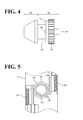
FIG. 4] FIG. 4 is a side view of the regulation member and a gear member, illustrating their structures. - [
FIG. 5] FIG. 5 illustrates an inner surface of the openable and closable door with its inner structure partially enlarged. - [
FIG. 6] FIG. 6 is an enlarged front view, partially a cross-sectional view, of the port of the control apparatus with its openable and closable door in open state, illustrating a structure of a brake function. - [
FIG. 7] FIG. 7 is a side view of a slide plate and a support member extracted to illustrate their whole structures. - [
FIG. 8] FIGs. 8A and 8B are each an enlarged side view, partially a cross-sectional view, of the regulation member at the openable and closable door, illustrating a structure of a brake release function. - [
FIG. 9] FIGs. 9A and 9B are diagrams each illustrating an area of plating. - [
FIG. 10] FIGs. 10A to 10C are diagrams each illustrating a method of operation in the case where the housing of a USB memory has a width smaller than a reference width of the slide plates. - [
FIG. 11] FIGs. 11A to 11E are diagrams each illustrating a method of operation in the case where the housing of the USB memory has a width greater than the reference width of the slide plates. - [
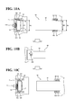
FIG. 12] FIGs. 12A to 12C are each a perspective view of the control apparatus according to a second embodiment, illustrating an external appearance of the control apparatus. - [
FIG. 13] FIG. 13A is a cross-sectional view of the holding mechanism taken along the line XIIIA-XIIIA shown inFIG. 13B , illustrating in detail a structure of the holding mechanism, and 13B is a side view of the holding mechanism with the housing partially shown in a cross-sectional view. - [
FIG. 14] FIGs. 14A to 14C are diagrams each illustrating an open-close operation of the openable and closable door. - [
FIG. 15] FIG. 15 is a cross-sectional view of the holding mechanism, illustrating a rotating operation of arm members implemented by handling of a push button. - [
FIG. 16] FIGs. 16A to 16C are diagrams each illustrating a method of operation for connection and disconnection of the USB memory. - [
FIG. 17] FIG. 17 is a cross-sectional view of the holding mechanism, illustrating a state in which the holding mechanism is holding a vertically asymmetrical USB memory. - [
FIG. 18] FIG. 18 is a perspective view of the control apparatus according to the first embodiment, illustrating an external appearance of the control apparatus with the USB cable connected thereto. - [
FIG. 19] FIG. 19 is a perspective view of the control apparatus according to the second embodiment, illustrating an external appearance of the control apparatus with the USB cable connected thereto. - [
FIG. 20] FIGs. 20A to 20C are diagrams each illustrating an open-close operation of an approximate L-shaped openable and closable door. - Embodiments will be described below by referring to the accompanying drawings.
- First, by referring to
FIGS. 1A to 1C , an external appearance of a control apparatus according to the first embodiment will be described. Acontrol apparatus 1 is a control apparatus that controls a control object, not shown. Examples of thecontrol apparatus 1 include Factory Automation (FA) machines such as a Programmable Logic Controller (PLC). To thecontrol apparatus 1, a Universal Serial Bus (USB) device is connectable and disconnectable so that data is transmitted between thecontrol apparatus 1 and the connected USB device based on a USB standard. In the following description, aUSB memory 50, which is a kind of USB device, will be exemplified to be connected to thecontrol apparatus 1. - As shown in
FIGs. 1A to 1C , aport 3 is disposed on one surface of ahousing 2 of the control apparatus 1 (on the left lower side as seen inFIGs. 1A to 1C ). Theport 3 accepts aconnector 51 of theUSB memory 50. In the following description, the side on which theport 3 is disposed will be referred to as the front side of thecontrol apparatus 1. Adjacent the front side of theport 3, an openable andclosable door 4 is disposed in an openable and closable manner with one side having a hinge structure. When the openable andclosable door 4 is open, the openable andclosable door 4 exposes theport 3 as shown inFIG. 1B , while when closed, the openable andclosable door 4 shields theport 3 as shown inFIG. 1A . Generally, USB ports implemented on Office Automation (OA) machines such as personal computers are exposed. Particularly in environments where FA machines are installed, this leaves a possibility of attachment of dust, oil mist, and other substances to the port, causing electrical short-circuit, communication disturbance, and other occurrences. For dust preventive purposes, thecontrol apparatus 1 is provided with the openable andclosable door 4. - As shown in
FIG. 1C , the openable andclosable door 4 includes aholding mechanism 100 to hold ahousing 52 of theUSB memory 50 when the openable andclosable door 4 is open. As shown inFIG. 1A , theholding mechanism 100 includes aregulation member 120 to regulate movement ofslide plates 101, described later, on the outer surface of the openable andclosable door 4. - Next, by referring to
FIGs. 2A and 2B , a structure of theholding mechanism 100 will be described in detail. As shown inFIGs. 2A and 2B , theholding mechanism 100 includes twoslide plates 101 to hold thehousing 52 of theUSB memory 50 on both sides of thehousing 52 so as to support thehousing 52. The twoslide plates 101 are disposed at one side and the other side (upper side and lower side in the example shown inFIGs. 2A and 2B ) of the inner surface of the openable andclosable door 4. Theslide plates 101 are movable in directions in which they come close to and apart from one another (in the vertical directions inFIGs. 2A and 2B ). Theslide plates 101 are examples of the holding members recited in the appended claims. - Specifically, each of the
slide plates 101 is secured at one end of acorresponding support 102. Thesupport 102 is in slidable contact with aguide 103, which is secured to the inner surface of the openable andclosable door 4. On the other end side of thesupport 102, arack gear 104 is disposed. Therack gear 104 meshes with a gear member 121 (seeFIGs. 3A to 3C ), which is integral with theregulation member 120 across the openable andclosable door 4. On the other end of thesupport 102, a slide-sidespring fixing portion 105 is disposed. Aspring 107 is disposed between the slide-sidespring fixing portion 105 and a door-sidespring fixing portion 106, which is disposed at the inner surface of the openable andclosable door 4. Thespring 107 at any time biases thecorresponding slide plate 101 to return to its reference position (the position shown inFIGs. 2A and 2B ). Thespring 107 is an example of the first biasing means recited in the appended claims. - The reference positions of the
respective slide plates 101 are predetermined at appropriate positions so that theslide plates 101 are within the area of the inner surface of the openable andclosable door 4. This enables the openable andclosable door 4 to open and close with theslide plates 101 positioned at their respective reference positions. Theport 3 is disposed at a further inward position than the surfaces of thehousing 2, so that when the openable andclosable door 4 is closed, theholding mechanism 100 including the slide plates 101 (but excluding the regulation member 120) is accommodated within the space defined by the inner surface of the openable andclosable door 4 and theport 3. - Each of the
slide plates 101 includes anelastic member 108 at a portion in contact with thehousing 52 of theUSB memory 50. Theelastic member 108 is made of rubber, elastomer, or similar material. Theelastic member 108 eliminates or minimizes slipping of theslide plate 101 and thehousing 52. In this embodiment, thehousing 52 of theUSB memory 50 has a shape that comes into contact with theslide plates 101 in a parallel manner. Even if the housing has a shape that is, for example, inclined relative to theslide plates 101 or has depressions and protrusions, theelastic members 108 can be elastically deformed to reliably hold the housing between theelastic members 108. Thus, theelastic members 108 are capable of holding between them USB devices of a wide variety of shapes, providing improved versatility. - Also at the inner surface of the openable and
closable door 4, apresser plate 109 is disposed as if to cover thegear member 121 from behind (from the right side inFIG. 2A and from the front side of the paper surface ofFIG. 2B ). Between thepresser plate 109 and thegear member 121, apresser spring 110 is disposed. Thepresser spring 110 at any time biases theintegrated regulation member 120 andgear member 121 toward the outer surface of the openable andclosable door 4. - Next, by referring to
FIGs. 3A to 3C , a relationship between the handling of theregulation member 120 and the operation of theslide plates 101 will be described. It is noted that inFIG. 3 , thepresser plate 109 and thepresser spring 110 are not shown for ease of description. -
FIG. 3A illustrates a state in which theslide plates 101 are positioned at their respective reference positions. In this state, when an operator turns theregulation member 120 in the anti-clockwise direction (with the openable andclosable door 4 seen from outside), thegear member 121 rotates in the clockwise direction (with the openable andclosable door 4 seen from inside), as represented by the arrow A1 shown inFIG. 3B . This brings thesupports 102 into sliding movement along theguides 103 against the compressive force of thesprings 107 as shown inFIG. 3B . That is, theslide plates 101 move in directions in which theslide plates 101 come close to one another, thereby diminishing the distance between theslide plates 101. When the operator turns theregulation member 120 in the clockwise direction (with the openable andclosable door 4 seen from outside), thegear member 121 rotates in the anti-clockwise direction (with the openable andclosable door 4 seen from inside), as represented by the arrow A2 shown inFIG. 3C . This brings thesupports 102 into sliding movement along theguides 103 against the stretching force of thesprings 107 as shown inFIG. 3C . That is, theslide plates 101 move in directions in which theslide plates 101 come apart from one another, thereby enlarging the distance between theslide plates 101. - As shown in
FIG. 3C , theslide plates 101 are operable over a wide area that exceeds the area of the inner surface of the openable andclosable door 4. This is because theholding mechanism 100 is disposed at the openable andclosable door 4, and opening the openable andclosable door 4 causes theholding mechanism 100 to move to outside of thecontrol apparatus 1, which eliminates any restrictions on the operation of theslide plates 101 associated with the housing shape of thecontrol apparatus 1 or other factors. For example, assume that a holding mechanism of a similar structure is disposed in a depression of the housing dedicated to the port. In this case, the operable range of the slide plates is limited to the size of the depression. Compared with this configuration, this embodiment greatly enlarges the operable range of theslide plates 101, which is significantly advantageous.
This, as a result, ensures holding of USB devices of a wide variety of sizes and shapes, and provides improved versatility. - Next, by referring to
FIGs. 4 to 6 , a brake function of theholding mechanism 100 will be described. When theslide plates 101 hold between them thehousing 52 of theUSB memory 50, the brake function stops theslide plates 101 at this holding position against the biasing force of thesprings 107, which at any time bias theslide plates 101 to return to their respective reference positions, as described above. It is noted that inFIG. 5 , thepresser plate 109, thepresser spring 110, and thegear member 121 are not shown for ease of description. - As shown in
FIGs. 4 and6 , thegear member 121 includes agear 122, atrunk 123, and anaxis 124. Thegear 122 has, on its outer circumference, teeth to mesh with therack gear 104. Thetrunk 123 couples thegear 122 and theregulation member 120 to one another while ensuring a predetermined distance therebetween. Thegear 122 and thetrunk 123 are coaxial to theaxis 124. As shown inFIG. 6 , theaxis 124 of thegear member 121 is inserted into theregulation member 120, and thus theregulation member 120 and thegear member 121 are coupled to one another into an integral configuration. On anend surface 125 of thegear 122 on the side of theregulation member 120, ahemispheric protrusion 126 is formed. While in this embodiment thegear 122, thetrunk 123, and theaxis 124 of thegear member 121 are integrally formed as shown inFIG. 6 , they may be formed as separate elements coupled to each other. - As shown in
FIG. 5 , the openable andclosable door 4 includes a throughhole 127 to penetrate through thetrunk 123 of thegear member 121. The throughhole 127 has an inner diameter approximately equal to the outer diameter of thetrunk 123 of thegear member 121. The circumferential portion of the throughhole 127 in the radial direction is thinner in thickness than the other portions of the openable andclosable door 4. The thinner portion functions as abearing 128 to slidably support thetrunk 123 of thegear member 121 in such a manner that thetrunk 123 can make rotational and linear motions. On anend surface 129 of the bearing 128 on the side of the door inner surface, a plurality ofround holes 130 are formed. The round holes 130 are capable of engaging with theprotrusion 126 of thegear member 121. The round holes 130 are arranged circumferentially at a predetermined pitch. - As shown in
FIG. 6 , theintegrated regulation member 120 andgear member 121 are at any time biased by thepresser spring 110 toward the outer surface of the openable and closable door 4 (the left side inFIG. 6 ). This brings theend surface 125 of thegear member 121 into contact with theend surface 129 of thebearing 128, thereby bringing theprotrusion 126 into engagement with one of the round holes 130. The engagement of theprotrusion 126 restricts the rotation of thegear member 121, and this in turn restricts the movement of thesupports 102, which mesh with thegear 122 of thegear member 121 at the rack gears 104. In this manner, brake acts on theslide plates 101. - When the
regulation member 120 is handled into rotation, theprotrusion 126 of thegear member 121 moves over theend surface 129 while straddling the round holes 130. That is, theregulation member 120 is handled into rotation by a handling force greater than the friction force acting between theprotrusion 126 and the round holes 130. In this respect, the pitch between theround holes 130 is set at a small level to prevent theprotrusion 126 from becoming stuck between adjoin round holes 130. This ensures that when theregulation member 120 is in non-handled state, theprotrusion 126 of thegear member 121 is engaged with any one of the round holes 130. As a result, while theregulation member 120 is in non-handled state, brake keeps acting on theslide plates 101 unless a release operation of the brake is performed, described later. - It is noted that because of the above-described configuration, the minimum movement of the
slide plates 101 is equivalent to the pitch between the circumferentially formed round holes 130. This leaves a possibility of a dimensional error between the width of thehousing 52 of theUSB memory 50 and the distance between theslide plates 101 positioned at their respective holding positions (each of which is the position that, as a result of theslide plates 101 moving on a minimum movement basis, most suitably corresponds to the width of thehousing 52 of the USB memory 50). In view of this, theelastic members 108 are disposed on theslide plates 101, as described above. Theelastic members 108 are elastically deformed and make the dimensional error tolerable, and come into contact with thehousing 52 at theslide plates 101, thereby reliably holding thehousing 52 between theelastic members 108. - In the above-described configuration, the
presser spring 110, theprotrusion 126, the round holes 130, thegear 122, and therack gear 104 are examples of the position fixing means recited in the appended claims. - Next, by referring to
FIGs. 7, 8A, and 8B , a brake release function of theholding mechanism 100 will be described.FIG. 8A illustrates a state in which brake is in action, whileFIG. 8B illustrates a state in which brake is released. - As shown in
FIG. 7 , therack gear 104 is disposed at the other side (the lower side inFIG. 7 ) of thesupport 102 opposite its one end (the upper end inFIG. 7 ) to which theslide plate 101 and theelastic member 108 are secured. Therack gear 104 is not disposed over the entire thickness of the support 102 (which is in the lateral direction inFIG. 7 ). Instead, therack gear 104 is disposed over approximately half the thickness of thesupport 102. The other half is a toothless,flat portion 131. - As shown in
FIG. 8A , in normal state, thepresser spring 110 biases thegear member 121 toward the outer surface of the openable and closable door 4 (the left side inFIG. 8 ), keeping theprotrusion 126 of thegear member 121 in engagement with one of the round holes 130 of the openable andclosable door 4. The engagement of theprotrusion 126 restricts the rotation of thegear member 121, and this in turn restricts the movement of thesupports 102, which mesh with thegear 122 of thegear member 121 at the rack gears 104.
In this manner, brake is acting on theslide plates 101. - As shown in
FIG. 8B , when theregulation member 120 is pushed into the inner surface of the openable and closable door 4 (the right side inFIG. 8 ), thegear 122 of thegear member 121 moves to theflat portion 131. This releases the mesh between therack gear 104 and thegear 122, and the biasing force of thesprings 107 moves thesupports 102 to return theslide plates 101 to their reference positions. In this manner, the brake on theslide plates 101 is released. - This kind of brake release is done when, for example, the
housing 52 of theUSB memory 50 to be removed has a smaller width than the reference width of the slide plates 101 (seeFIGs. 10A to 10C , described later). Instead of releasing the brake, it is also possible to removesuch USB memory 50 by handling theregulation member 120 into clockwise rotation and thereby enlarging the distance between theslide plates 101. - It is noted that the openable and
closable door 4 includes an acceptingspace 132 at the bearing 128 on the outer surface side of the door (the left side inFIGs. 8A and 8B ). The acceptingspace 132 ensures pushing of theregulation member 120. At a center portion of thepresser plate 109, anopening 133 is disposed to accept theaxis 124 of thegear member 121 when theregulation member 120 is pushed inwardly. - In the above-described configuration, the
regulation member 120, the acceptingspace 132, and theflat portion 131 are examples of the fixation releasing means recited in the appended claims. - Next, by referring to
FIGs. 9A and 9B , an area of plating will be described. In thecontrol apparatus 1, there is a possibility of theport 3 becoming a source of emitting noise to outside the apparatus, or a possibility of theport 3 becoming a source of receiving noise resulting in malfunction. In view of this, this embodiment provides a platedportion 5, which is subjected to plating treatment, as if to surround theport 3 as shown inFIG. 9A (where the area of the platedportion 5 is shaded). This embodiment also provides a platedportion 6, which is subjected to plating treatment over approximately the entire inner surface of the openable andclosable door 4 as shown inFIG. 9B (where the area of the platedportion 6 is shaded). - Examples of the plating material to be used include a conductive material such as copper and nickel. The plated
portions housing 2. It is noted that theholding mechanism 100 made up of theslide plates 101 and other elements is disposed on the platedportion 6 at the inner surface of the openable andclosable door 4. - When the
USB memory 50 is in connection state with the openable andclosable door 4 open, the above-described noise emission and reception are eliminated or minimized mainly by the platedportion 5, which is formed around theport 3. When theUSB memory 50 is removed and the openable andclosable door 4 is in closed state, the above-described noise emission and reception are eliminated or minimized mainly by the platedportion 6, which is formed on the inner surface of the openable andclosable door 4. - Next, by referring to
FIGs. 10A to 10C and11 , a method of operation for connection and disconnection of theUSB memory 50 will be described. It is noted that in this embodiment, the distance between theelastic members 108 when theslide plates 101 are positioned at the above-described reference positions will be referred to as a "reference width". - First, by referring to
FIGs. 10A to 10C , description will be made with regard to the case where the width of the housing of the USB memory is smaller than the reference width of the slide plates. As shown inFIG. 10A , when the width, WS, of thehousing 52 of theUSB memory 50 is smaller than the reference width, Wo, of theslide plates 101, the operator opens the openable andclosable door 4 and inserts theconnector 51 of theUSB memory 50 directly into theport 3, thus connecting theUSB memory 50 to thecontrol apparatus 1. This makes theUSB memory 50 supported in the form of a cantilever with thehousing 52 passed between theslide plates 101. - Next, as shown in
FIG. 10B , the operator handles theregulation member 120 into rotation in the anti-clockwise direction as represented by the arrow A3 shown inFIG. 10B . As described above by referring toFIG. 3B , this brings thegear member 121 into rotation in the clockwise direction (with the openable andclosable door 4 seen from inside). This in turn brings thesupports 102 into sliding movement along theguides 103 against the compressive force of thesprings 107. That is, theslide plates 101 move in directions in which theslide plates 101 come close to one another. - When the
elastic members 108 move to positions at which to come into contact with thehousing 52, thehousing 52 of theUSB memory 50 is held between theslide plates 101, as shown inFIG. 10C . Thus, theUSB memory 50 is connected, and this connected state is maintained with high holding strength. - When the
USB memory 50 is to be removed, the operator may handle theregulation member 120 into rotation in the clockwise direction, which is opposite the above-described direction, thereby separating theslide plates 101 from one another. More simply, it is possible to inwardly push theregulation member 120. This releases the brake on theslide plates 101 as described above, and theslide plates 101 automatically return to their respective reference positions. Then, theconnector 51 of theUSB memory 50 is pulled out of theport 3, and thus theUSB memory 50 is removed from thecontrol apparatus 1. - Next, by referring to
FIGs. 11A to 11E , description will be made with regard to the case where the width of the housing of the USB memory is larger than the reference width of the slide plates. As shown inFIG. 11A , when the width, WL, of thehousing 52 of theUSB memory 50 is larger than the reference width Wo of theslide plates 101, theUSB memory 50 cannot be directly connected to thecontrol apparatus 1. - In view of this, as shown in
FIG. 11B , with the openable andclosable door 4 in open state, the operator handles theregulation member 120 into rotation in the clockwise direction as represented by the arrow A4. As described above by referring toFIG. 3C , this brings thegear member 121 into rotation in the anti-clockwise direction (with the openable andclosable door 4 seen from inside). This in turn brings thesupports 102 into sliding movement along theguides 103 against the stretching force of thesprings 107. That is, theslide plates 101 move in directions in which theslide plates 101 come apart from one another. - As shown in
FIG. 11C , when theslide plates 101 move to positions at which the width W of the slide plates 101 (more precisely, the distance between the elastic members 108) is larger than the width WL of thehousing 52, the operator inserts theconnector 51 of theUSB memory 50 into theport 3, thus connecting theUSB memory 50 to thecontrol apparatus 1. This makes theUSB memory 50 supported in the form of a cantilever with thehousing 52 passed between theslide plates 101. - Next, as shown in
FIG. 11D , the operator handles theregulation member 120 into rotation in the anti-clockwise direction as represented by the arrow A5. As described above by referring toFIG. 3B , this brings thegear member 121 into rotation in the clockwise direction (with the openable andclosable door 4 seen from inside). This in turn brings thesupports 102 into sliding movement along theguides 103 against the compressive force of thesprings 107. That is, theslide plates 101 move in directions in which theslide plates 101 come close to one another. - When the
elastic members 108 move to positions at which to come into contact with thehousing 52, thehousing 52 of theUSB memory 50 is held between theslide plates 101 as shown inFIG. 11E . Thus, theUSB memory 50 is connected, and this connected state is maintained with high holding strength. - When the
USB memory 50 is to be removed, the operator handles theregulation member 120 into rotation in the clockwise direction, which is opposite the above-described direction, thereby separating theslide plates 101 from one another. Then, theconnector 51 of theUSB memory 50 is pulled out of theport 3, and thus theUSB memory 50 is removed from thecontrol apparatus 1. It is noted that in this state theslide plates 101 protrude beyond the openable andclosable door 4 as shown inFIG. 11C , making it impossible to close the openable andclosable door 4. However, inwardly pushing theregulation member 120 makes theslide plates 101 automatically return to their respective reference positions, after which the openable andclosable door 4 can be closed. - With the above-described
control apparatus 1 according to this embodiment, inserting theconnector 51 of theUSB memory 50 into theport 3 connects theUSB memory 50 to thecontrol apparatus 1, while pulling theconnector 51 out of theport 3 removes theUSB memory 50 from thecontrol apparatus 1. Adjacent theport 3 of thecontrol apparatus 1, the openable andclosable door 4 is disposed. During the period of disconnection time of theUSB memory 50, the openable andclosable door 4 is closed to shield theport 3, while during the period of connection time of theUSB memory 50, the openable andclosable door 4 is open to expose theport 3. - At the openable and
closable door 4, theholding mechanism 100 is disposed. Theholding mechanism 100 holds thehousing 52 of theconnected USB memory 50, and this eliminates or minimizes pulling of theconnector 51 of theUSB memory 50 out of theport 3 and maintains the connection state of theUSB memory 50 with high holding strength. Since theholding mechanism 100 is disposed at the openable andclosable door 4, when the openable andclosable door 4 opens, theholding mechanism 100 moves to outside of thehousing 2 of thecontrol apparatus 1. This ensures a structure that eliminates any restrictions on the holding operation of theholding mechanism 100 associated with the housing shape of thecontrol apparatus 1 or other factors. This ensures holding of thehousing 52 of theUSB memory 50 even when it comes in a wide variety of sizes and shapes, and provides improved versatility. Additionally, during the period of disconnection time of theUSB memory 50, the openable andclosable door 4 is closed to shield theport 3. This eliminates or minimizes electrical short-circuit of theport 3 and attachment, to theport 3, of dust and other substances that can cause communication disturbance or other occurrences. - It is particularly noted that in this embodiment, the
holding mechanism 100 includes, at the inner surface of the openable andclosable door 4, the twoslide plates 101 to hold thehousing 52 of theUSB memory 50 between theslide plates 101. Theslide plates 101 are movable in directions in which theslide plates 101, which are disposed on one side and the other side of the openable andclosable door 4, come close to and apart from one another. This ensures that when thehousing 52 of theUSB memory 50 to be connected has a large width, theslide plates 101 move apart from one another to enlarge the distance between theslide plates 101, which permits theslide plates 101 to holdsuch housing 52 between theslide plates 101. When thehousing 52 of theUSB memory 50 to be connected has a small width, theslide plates 101 move close to one another to diminish the distance between theslide plates 101, which permits theslide plates 101 to holdsuch housing 52 between theslide plates 101. In this manner, thehousing 52 of theUSB memory 50 is held even when it comes in a wide variety of sizes and shapes, which provides improved versatility. Additionally, theslide plates 101 are disposed at the inner surface of the openable andclosable door 4. This ensures that closing the openable andclosable door 4 during the period of disconnection time of theUSB memory 50 eliminates or minimizes exposure of theslide plates 101 to the outside. This in turn eliminates or minimizes a disfigured external appearance of thecontrol apparatus 1. - It is particularly noted that in this embodiment, the
holding mechanism 100 includes, at the outer surface of the openable andclosable door 4, theregulation member 120 to regulate movement of theslide plates 101 in directions in which theslide plates 101 come close to and apart from one another. With the use of theregulation member 120, the operator can easily move theslide plates 101. This improves operability associated with connection and disconnection of theUSB memory 50. - It is particularly noted that in this embodiment, the distance between the
slide plates 101 is adjusted while theslide plates 101 are moving in directions in which they come close to or apart from one another. Then at holding positions corresponding to the size of thehousing 52 of theUSB memory 50, theslide plates 101 hold thehousing 52 between theslide plates 101 so as to support thehousing 52. In this respect, the brake function implemented by the engagement of theprotrusion 126 of thegear member 121 with one of the round holes 130 of the openable andclosable door 4 fixes the positions of theslide plates 101 at their respective holding positions. This eliminates or minimizes displacement of theslide plates 101 off the holding positions due to, for example, vibration, shock, and other kinds of impact, resulting in improved holding function of theUSB memory 50. Even though theslide plates 101 are at any time biased by thesprings 107 to return to the reference positions, the brake function keeps theslide plates 101 at the holding positions. - It is particularly noted that in this embodiment, by the operator inwardly pushing the
regulation member 120, the mesh of the rack gears 104 of thesupports 102 with thegear 122 of thegear member 121 is released, and thus the brake on theslide plates 101 is released. When the brake is released, theslide plates 101 are returned to their respective reference positions by the biasing force of thesprings 107. This ensures that when the openable andclosable door 4 is closed after theUSB memory 50 has been removed, the movedslide plates 101 are easily and quickly returned to their respective reference positions. This greatly saves labor associated with returning theslide plates 101 to their respective reference positions during the time when the openable andclosable door 4 is closed. - It is particularly noted that in this embodiment, the
slide plates 101 each include theelastic member 108 at the portion of contact with thehousing 52 of theUSB memory 50. This eliminates or minimizes slipping between theslide plates 101 and thehousing 52, and the holding function for theUSB memory 50 further improves. Even if thehousing 52 of theUSB memory 50 has a shape that is, for example, inclined relative to theslide plates 101 or has depressions and protrusions, theelastic members 108 can be elastically deformed to reliably hold thehousing 52 between theelastic members 108. Thus, theelastic members 108 are capable of holding between them thehousing 52 of theUSB memory 50 even if it comes in a wide variety of shapes, providing improved versatility. Further in this embodiment, theslide plates 101 move stepwise on the basis of the pitch between the round holes 130. Hence, disagreement can arise between the width of the housing of theUSB memory 50 and the distance between theslide plates 101 at their respective holding positions. In this case, theelastic members 108, which are disposed on theslide plates 101, are elastically deformed upon contact with thehousing 52 and make the dimensional error tolerable. Thus, theelastic members 108 reliably hold thehousing 52 between theelastic members 108. - It is particularly noted that in this embodiment, the inner surface of the openable and
closable door 4 is plated with a conductive material. This eliminates or minimizes malfunction of thecontrol apparatus 1 caused by, when the openable andclosable door 4 is in closed state during the period of disconnection time of theUSB memory 50, theport 3 becoming a source of emitting noise to outside thecontrol apparatus 1 or becoming a source of receiving noise. Also, a certain area around theport 3 is plated, and this eliminates or minimizes the above-described noise emission and reception also when theUSB memory 50 is in connection state with the openable andclosable door 4 open. - Next, by referring to
FIGs. 12A to 17 , a second embodiment will be described. The second embodiment is similar to the first embodiment described above in maintaining the connected state of thehousing 52 of theconnected USB memory 50 with high holding strength by holding thehousing 52. The second embodiment is different from the first embodiment in the configuration of the holding mechanism. - First, by referring to
FIGs. 12A to 12C , the external appearance of the control apparatus according to the second embodiment will be described. As shown inFIGs. 12A to 12C , aport 13 is disposed on one surface of ahousing 12 of a control apparatus 11 (on the left lower side as seen inFIGs. 12A to 12C ). Theport 13 accepts theconnector 51 of theUSB memory 50. In the following description, the side on which theport 13 is disposed will be referred to as the front side of thecontrol apparatus 11. Adjacent the front side of theport 13, an openable andclosable door 14 is disposed in an openable and closable manner with one side having a hinge structure. When the openable andclosable door 14 is open, the openable andclosable door 14 exposes theport 13 as shown inFIG. 12B , while when closed, the openable andclosable door 14 shields theport 13 as shown inFIG. 12A . As shown inFIG. 12C , the openable andclosable door 14 includes aholding mechanism 200 to hold thehousing 52 of theUSB memory 50 when the openable andclosable door 14 is open. As shown inFIG. 12A , theholding mechanism 200 includes apush button 220 to regulate movement of holdingmembers 201 on the outer surface of the openable andclosable door 14. - Next, by referring to
FIGs. 13A to 15 , a structure of theholding mechanism 200 will be described in detail. As shown inFIGs. 13A and 13B , theholding mechanism 200 includes two holdingmembers 201 to hold thehousing 52 of theUSB memory 50 on both sides of thehousing 52 so as to support thehousing 52. The two holdingmembers 201 are disposed at one side and the other side (upper side and lower side in this example) of the inner surface of the openable andclosable door 14. The holdingmembers 201 are movable in directions in which the holdingmembers 201 come close to and apart from one another (in the vertical directions inFIG. 15 ). - Specifically, each of the holding
members 201 is disposed at the distal end of a corresponding one ofarm members 202. Each of thearm members 202 is curved in an approximately dogleg shape so as to avoid contact with the comers of thehousing 52 when the holdingmembers 201 hold thehousing 52 of theUSB memory 50 between the holdingmembers 201. Each of thearm members 202 is rotatable about a corresponding one ofaxes 203 disposed at the upper side and the lower side of the inner surface of the openable andclosable door 14. Each of theaxes 203 is disposed at the openable andclosable door 14 through axis supports 204 each having a larger diameter than the diameter of thecorresponding axis 203. In this embodiment, as shown inFIGs. 14A to 14C , the openable andclosable door 14 includesside walls axes 203 has its both ends supported by theside walls - As shown in
FIG. 13B , each of theaxes 203 includes atorsion coil spring 205 having one end secured to thecorresponding arm member 202 and another end secured to thecorresponding axis 203. Thetorsion coil spring 205 at any time biases thearm member 202 into rotation in a direction in which the holdingmembers 201 come close to one another (in the arrow X direction inFIG. 15 ). When thepush button 220 is in non-pushed state, the biasing force of the coil springs 205 keeps thearm members 202 and the holdingmembers 201 within the openable and closable door 14 (within the space between theside walls FIGs. 13A and 13B andFIGs. 14A to 14C . Thetorsion coil spring 205 is an example of the second biasing means recited in the appended claims. InFIGs. 14A to 14C , thetorsion coil spring 205 is not shown. -
FIGs. 14A to 14C each illustrate an open-close operation of the openable andclosable door 14. The openable andclosable door 14 is rotatable relative to thehousing 12 about anaxis 14c, which is a rotation axis disposed on the rear side of theside wall 14a (on the upper side inFIGs. 14A to 14C ). As shown inFIG. 14A , when the openable andclosable door 14 is in closed state, the openable andclosable door 14 as a whole, including theside walls depression 12a of thehousing 12 together with theholding mechanism 200. The openable andclosable door 14 can be turned into rotation as shown inFIG. 14B . When the openable andclosable door 14 is rotated approximately 90 degrees about theaxis 14c as shown inFIG. 14C , the openable andclosable door 14 is in open state and theport 13 is exposed. As shown inFIG. 14C , during the time when the openable andclosable door 14 is open, theside wall 14b functions as a cover over the front side of theholding mechanism 200. This provides protection for theholding mechanism 200, eliminating or minimizing contact of theUSB memory 50 and the operator's fingers with theholding mechanism 200. This also eliminates or minimizes a disfigured external appearance of thecontrol apparatus 11 when the door is open. - As shown in
FIG. 13A , thepush button 220 is disposed outside the openable andclosable door 14 and coupled to a rectangular pushingplate 222 through anaxis 221, which penetrates through the openable andclosable door 14. The pushingplate 222 is disposed on the inner side of the openable andclosable door 14. The ends of the pushingplate 222 in its longitudinal direction are in contact withrespective protrusions 202a of thearm members 202, which are disposed at the upper side and the lower side of the openable andclosable door 14. As shown inFIG. 15 , when thepush button 220 is pushed inwardly toward the openable andclosable door 14, theaxis 221 and the pushingplate 222 are brought into movement to push theprotrusions 202a. Thearm members 202 are then brought into rotation in a direction in which the holdingmembers 201 come apart from one another (in the arrow Y direction inFIG. 15 ) against the biasing force of the torsion coil springs 205. - As shown in
FIG. 13A , theaxis 221 includes acoil spring 223 to at any time bias thepush button 220 toward the side opposite the openable andclosable door 14. When thepush button 220 is released, the biasing force of thecoil spring 223 returns thepush button 220, theaxis 221, and the pushingplate 222 to their respective pre-pushing positions. As a result, as shown inFIG. 15 , the biasing force of the torsion coil springs 205 brings thearm members 202 into rotation in a direction in which the holdingmembers 201 come close to one another (in the arrow X direction inFIG. 15 ). Thepush button 220 is an example of the regulation member recited in the appended claims. InFIGs. 14A to 14C and15 , thecoil spring 223 is not shown. - With the configuration of the
holding mechanism 200 described above, handling (pushing and releasing) thepush button 220 brings thearm members 202 into rotation in the Y direction and the X direction as shown inFIG. 15 . Here, the holdingmembers 201 move in directions in which the holdingmembers 201 come close to and apart from one another while ensuring that the distance between the holdingmembers 201 is in the range of G1 to G2. - Each of the holding
members 201 has an approximately cylindrical shape. The entire body of each holdingmember 201 is made of an elastic material such as rubber and elastomer. The holdingmembers 201 have their outer circumference surfaces of the cylindrical shapes come into contact with thehousing 52 of theUSB memory 50. This ensures that the holdingmembers 201 uniformly contact thehousing 52 even if the holdingmembers 201 change their angles by the rotation of thearm members 202. Additionally, employing an elastic material for the entire body of each holdingmember 201 ensures that thehousing 52 makes contact with the elastic material no matter where on the outer circumference surface of the holdingmember 201. This eliminates or minimizes slipping between the holdingmembers 201 and thehousing 52. Even if thehousing 52 has a shape that is, for example, inclined relative to the holdingmembers 201 or has depressions and protrusions, the holdingmembers 201 can be elastically deformed to reliably hold the housing between the holdingmembers 201. Thus, the holdingmembers 201 are capable of holding between them USB devices of a wide variety of shapes, providing improved versatility. - It is also possible to employ an elastic material on a part of each holding member 201 (for example, only on the outer circumference surface), instead of the entire body of holding
member 201. - In the
control apparatus 11 according to this embodiment, similarly to the first embodiment described above, a certain area around theport 13 is plated, and approximately the entire inner surface of the openable andclosable door 14 is plated. This will not be elaborated here. - Next, by referring to
FIGs. 16A to 16C , a method of operation for connection and disconnection of theUSB memory 50 will be described. - As described above, when the
push button 220 is in non-pushed state, thearm members 202 and the holdingmembers 201 are accommodated within the openable and closable door 14 (which is the state shown inFIG. 13A ). In this state, when the operator pushes thepush button 220 inwardly toward the openable andclosable door 14 as shown inFIG. 16A , thearm members 202 are brought into rotation to move the holdingmembers 201 in directions in which the holdingmembers 201 come apart from one another. In this respect, thepush button 220 is pushed inwardly such that the distance between the holdingmembers 201 is greater than thehousing 52 of theUSB memory 50. - Next, as shown in
FIG. 16B , the operator inserts theconnector 51 of theUSB memory 50 into theport 13, thus connecting theUSB memory 50 to thecontrol apparatus 11. This makes theUSB memory 50 supported in the form of a cantilever with thehousing 52 passed between the holdingmembers 201. - Next, as shown in
FIG. 16C , when the operator releases thepush button 220, thecoil spring 223 returns thepush button 220, theaxis 221, and the pushingplate 222 to their respective pre-pushing positions, and the torsion coil springs 205 bring therespective arm members 202 into rotation in directions in which the holdingmembers 201 come close to one another. This ensures that when the holdingmembers 201 come in contact with thehousing 52 of theUSB memory 50, thehousing 52 is held between the holdingmembers 201. Thus, theUSB memory 50 is connected, and this connected state is maintained with high holding strength. - When the
USB memory 50 is to be removed, the above-described procedure may be applied in reverse. Specifically, the operator pushes again thepush button 220 inwardly so as to move the holdingmembers 201 apart from one another. Then, theconnector 51 of theUSB memory 50 is pulled out of theport 3, and thus theUSB memory 50 is removed from thecontrol apparatus 11. - In the
control apparatus 11 according to this embodiment described hereinbefore, similarly to the first embodiment described above, theholding mechanism 200 holds thehousing 52 of theconnected USB memory 50. This eliminates or minimizes removal of theconnector 51 of theUSB memory 50 from theport 3, and maintains the connection state of theUSB memory 50 with high holding strength. Additionally, theholding mechanism 200 has no gear structures or similar structures. This ensures a simplified structure with reduced piece-part count. Further, the operator only has to push thepush button 220, which significantly facilitates the connecting and disconnecting operation of theUSB memory 50. - Further, because of the structure of rotating the
arm members 202 by the biasing force of the respective, separate torsion coil springs 205, thearm members 202 rotate independently of one another. As a result, as shown inFIG. 17 , even when thehousing 52 of theUSB memory 50 has different vertical dimensions h1 and h2, which are based on a center line Lo of theconnector 51 of the USB memory 50 (the center line of the port 3), the holdingmembers 201 are capable of holdingsuch housing 52 between the holdingmembers 201. Thus, the holdingmembers 201 are capable of holding between them a vertically asymmetrical USB device, providing further improved versatility. - It will be appreciated that the first and second embodiments should not be construed in a limiting sense. Numerous modifications and variations are possible in light of the above teachings.
- For example, while in the above-described embodiments a USB memory has been illustrated as an example of the USB device to be connected and disconnected, other kinds of USB devices may be employed. Examples include: external memory storages such as a hard disc drive; input devices such as a keyboard and a mouse; communication devices such as a hub; other devices to be connected by cable through USB; communication devices of wireless LAN (Local Area Network); interfaces for wireless mice; and other devices without cables. Thus, a wide variety of USB devices can be connected.
FIGs. 18 and 19 are perspective views respectively of thecontrol apparatuses USB cable 7 connected thereto. - While in the above-described embodiments the
control apparatus 1 has been illustrated as being an FA machine such as a PLC, this should not be construed in a limiting sense. The control apparatus may also be an Office Automation (OA) machine such as a personal computer. Furthermore, the control apparatus may not necessarily be such a control apparatus that controls some control object. Any other machines are possible insofar as the above-described USB devices are connectable. - Also in the above-described embodiments, the openable and
closable doors housing 52 of theUSB memory 50 is held from the vertical direction. This, however, should not be construed in a limiting sense. For example, the openable and closable door may be opened in the vertical direction of the apparatus, and thehousing 52 may be held from the lateral direction. - Also in the above-described embodiments, the operator regulates the movement of the
slide plates 101 or the holdingmembers 201 manually by using theregulation member 120 or thepush button 220. This, however, should not be construed in a limiting sense. It is also possible to automatically regulate theslide plates 101 or the holdingmembers 201 by using a motor. - Also in the second embodiment described above, the
push button 220 has been illustrated as an example of the regulation member such that by pushing thepush button 220, thearm members 202 rotate in expanding directions (in directions in which the holdingmembers 201 come apart from one another). This, however, should not be construed in a limiting sense. The regulation member may also be a pull button, in which case thearm members 202 rotate in expanding directions by pulling the button. Here, when the operator discontinues pulling of the button, the button may be forced back in place by spring force, and thearm members 202 and the holdingmembers 201 may be accommodated within the openable andclosable door 14. - Also in the second embodiment described above, the openable and
closable door 14 has been illustrated as having an approximate U-shape having theside walls closable door 14 may also have, for example, an approximate L-shape (a structure without theside wall 14b), supporting only one end of each of theaxes 203 in the form of a cantilever, as shown inFIGs. 20A to 20C . In this case, theaxis 14c is disposed at the front side of theside wall 14a (the lower side inFIGs. 20A to 20C ). This provides an effect of eliminating or minimizing protrusion of the openable andclosable door 14 to a lateral side of the housing 12 (the left side inFIGs. 20A to 20C ) when the openable andclosable door 14 is opened, as shown inFIGs. 20A to 20C . If the openable andclosable door 14 has an approximate U-shape and itsaxis 14c is disposed at the front side of theside wall 14a, it is necessary to enlarge thedepression 12a so as to avoid interference between theside wall 14b and the inner wall of thedepression 12a when the door is opened and closed. This causes an increase in size of thehousing 12. In view of this, in this modification, the openable andclosable door 14 has an approximate L-shape and itsaxis 14c is disposed at the front side of theside wall 14a. This eliminates or minimizes projection of the openable andclosable door 14 without causing an increase in size of thehousing 12. - Otherwise, the above-described embodiments and modifications may be combined in any manner deemed suitable. Obviously, numerous modifications and variations of the present invention are possible in light of the above teachings. It is therefore to be understood that within the scope of the appended claims, the invention may be practiced otherwise than as specifically described herein.
-
- 1
- Control apparatus
- 3
- Port
- 4
- Openable and closable door
- 11
- Control apparatus
- 14
- Openable and closable door
- 50
- USB memory (USB device)
- 51
- Connector
- 52
- Housing
- 100
- Holding mechanism
- 101
- Slide plate (holding member)
- 104
- Rack gear (position fixing means)
- 107
- Spring (first biasing means)
- 108
- Elastic member
- 110
- Presser spring (position fixing means)
- 120
- Regulation member (fixation releasing means)
- 122
- Gear (position fixing means)
- 126
- Protrusion (position fixing means)
- 130
- Round hole (position fixing means)
- 131
- Flat portion (fixation releasing means)
- 132
- Accepting space (fixation releasing means)
- 200
- Holding mechanism
- 201
- Holding member
- 203
- Axis
- 205
- Torsion coil spring (second biasing means)
- 220
- Push button (regulation member)
Claims (12)
- A control apparatus to which a USB device is connectable and from which the USB device is disconnectable, characterized by:a port into which a connector of the USB device is insertable;an openable and closable door disposed adjacent the port, the openable and closable door being configured to open so as to expose the port and configured to close so as to shield the port; anda holding mechanism disposed at the openable and closable door and configured to hold a housing of the USB device when the openable and closable door is open.
- The control apparatus according to claim 1,
wherein the holding mechanism comprises at least two holding members behind an inner surface of the openable and closable door, the at least two holding members being configured to hold the housing of the USB device between the at least two holding members so as to support the housing of the USB device, and
wherein the holding members are movable in directions in which one holding member among the holding members disposed at one side of the inner surface of the openable and closable door and another holding member among the holding members disposed at another side of the inner surface of the openable and closable door come close to and apart from one another. - The control apparatus according to claim 2, wherein the holding mechanism comprises a regulation member at an outer surface of the openable and closable door, the regulation member being configured to regulate the holding members to move in the directions in which the holding members come close to and apart from one another.
- The control apparatus according to claim 2 or 3, wherein the holding mechanism comprises position fixing means for fixing the holding members at respective holding positions corresponding to a size of the housing of the USB device.
- The control apparatus according to claim 4, wherein the holding mechanism comprises
first biasing means for biasing the holding members back to predetermined reference positions at which the openable and closable door is closable, and
fixation releasing means for releasing the holding members fixed by the position fixing means so as to permit the holding members to return to the respective reference positions by biasing force of the first biasing means. - The control apparatus according to any one of claims 2 to 5, wherein the holding members each comprise an elastic member at a portion of contact with the housing of the USB device.
- The control apparatus according to claim 3, wherein the holding mechanism comprises at least two arm members each being rotatable about a corresponding one of axes disposed at the openable and closable door, wherein the holding members are each disposed at a distal end of a corresponding one of the at least two arm members, the holding members being movable in directions in which the holding members come close to and apart from one another by rotation of the at least two arm members.
- The control apparatus according to claim 7, wherein the holding mechanism comprises second biasing means, disposed at the axis, for rotating the arm members in directions in which the holding members come close to one another.
- The control apparatus according to claim 8, wherein the regulation member comprises a push button configured to rotate the arm members in directions in which the holding members come apart from one another against biasing force of the second biasing means.
- The control apparatus according to any one of claims 7 to 9, wherein the holding members each comprise an elastic material.
- The control apparatus according to any one of claims 1 to 10, wherein an inner surface of the openable and closable door is plated at least partially.
- The control apparatus according to any one of claims 1 to 11, wherein the USB device comprises at least one of a USB memory and a USB cable.
Applications Claiming Priority (2)
| Application Number | Priority Date | Filing Date | Title |
|---|---|---|---|
| JP2010248739 | 2010-11-05 | ||
| PCT/JP2011/068788 WO2012060143A1 (en) | 2010-11-05 | 2011-08-19 | Control device |
Publications (2)
| Publication Number | Publication Date |
|---|---|
| EP2637259A1 true EP2637259A1 (en) | 2013-09-11 |
| EP2637259A4 EP2637259A4 (en) | 2015-01-07 |
Family
ID=46024265
Family Applications (1)
| Application Number | Title | Priority Date | Filing Date |
|---|---|---|---|
| EP11837796.9A Withdrawn EP2637259A4 (en) | 2010-11-05 | 2011-08-19 | CONTROL DEVICE |
Country Status (6)
| Country | Link |
|---|---|
| US (1) | US9033718B2 (en) |
| EP (1) | EP2637259A4 (en) |
| JP (1) | JP5578339B2 (en) |
| KR (1) | KR101457828B1 (en) |
| CN (1) | CN103190039B (en) |
| WO (1) | WO2012060143A1 (en) |
Families Citing this family (10)
| Publication number | Priority date | Publication date | Assignee | Title |
|---|---|---|---|---|
| CN103190039B (en) * | 2010-11-05 | 2015-09-09 | 株式会社安川电机 | Control device |
| TWI462025B (en) * | 2011-11-30 | 2014-11-21 | Wistron Corp | Card reader having movable card insertion mechanism and electronic device |
| KR101388893B1 (en) | 2013-03-22 | 2014-04-23 | (주)테크베이스 | Security apparatus between usb host device and peripheral device |
| CN104111706B (en) * | 2013-04-16 | 2018-03-20 | 鸿富锦精密电子(天津)有限公司 | Cabinet |
| CN107681345B (en) * | 2016-08-01 | 2021-03-23 | 东莞莫仕连接器有限公司 | Electrical connector assembly |
| CN106627235B (en) * | 2017-01-04 | 2020-05-15 | 上海蔚来汽车有限公司 | Full-automatic dustproof system for quick-change connector of electric automobile |
| CN108777393B (en) * | 2018-05-29 | 2020-01-07 | 安徽天斯努信息技术股份有限公司 | A connection interface for protective cloud printing terminal equipment |
| CN110212364B (en) * | 2019-04-17 | 2020-12-08 | 重庆彤星科技有限公司 | Information transmission interface of automobile electric control system |
| JP7409891B2 (en) * | 2020-01-31 | 2024-01-09 | 東芝ライフスタイル株式会社 | refrigerator |
| CN112510438A (en) * | 2020-12-16 | 2021-03-16 | 杭州箬逸机器人科技有限公司 | Intelligent manufacturing efficient dustproof computer USB connection fixing mechanism |
Family Cites Families (22)
| Publication number | Priority date | Publication date | Assignee | Title |
|---|---|---|---|---|
| DE3327087C1 (en) * | 1983-07-27 | 1984-08-16 | Franz 8018 Grafing Lechner | Intermediate piece for securing mains plugs against unauthorized use of the device |
| US5483419A (en) * | 1991-09-24 | 1996-01-09 | Teac Corporation | Hot-swappable multi-cartridge docking module |
| JPH0714575U (en) * | 1991-12-27 | 1995-03-10 | センチュリーメディカル株式会社 | Connector locking mechanism |
| US5288945A (en) * | 1992-06-30 | 1994-02-22 | Bruce Wayne K | Electric outlet safety plate |
| JPH09147980A (en) * | 1995-11-20 | 1997-06-06 | Hitachi Ltd | Plug removal cover structure |
| US5735701A (en) * | 1995-12-11 | 1998-04-07 | Intel Corporation | Locking power cable interface guard |
| JP2001118618A (en) * | 1999-10-18 | 2001-04-27 | Jst Mfg Co Ltd | connector |
| JP3453131B2 (en) | 2001-11-15 | 2003-10-06 | モルデック株式会社 | Integrated circuit connector and integrated circuit mounting assembly |
| JP4131693B2 (en) * | 2003-09-30 | 2008-08-13 | ホシデン株式会社 | connector |
| US7264489B2 (en) * | 2004-10-27 | 2007-09-04 | Hewlett-Packard Development Company, L.P. | Dual connector assembly with pivoting keep-out member |
| DE602006020241D1 (en) * | 2005-01-07 | 2011-04-07 | Apple Inc | COUPLING ARRANGEMENT FOR USB CONNECTOR AND SOCKET |
| JP2006294260A (en) * | 2005-04-05 | 2006-10-26 | Sharp Corp | Plug connection device and plug connection method |
| JP4984563B2 (en) * | 2006-02-17 | 2012-07-25 | 株式会社Jvcケンウッド | Electronic device connector retaining structure. |
| US7364458B1 (en) * | 2006-12-20 | 2008-04-29 | Lotes Co., Ltd. | Electrical connector |
| US7374454B1 (en) * | 2007-06-05 | 2008-05-20 | Sure-Fire Electrical Corporation | Wall plate assembly |
| JP2009135034A (en) * | 2007-11-30 | 2009-06-18 | Chugoku Electric Power Co Inc:The | Connecting plug and measuring cord |
| JP2010021070A (en) * | 2008-07-11 | 2010-01-28 | Toshiba Corp | Usb plug coming-off prevention device |
| KR101449042B1 (en) * | 2008-07-15 | 2014-10-08 | 현대자동차주식회사 | United States Port |
| JP5547898B2 (en) * | 2009-03-04 | 2014-07-16 | パナソニック株式会社 | Lid opening / closing device |
| CN103190039B (en) * | 2010-11-05 | 2015-09-09 | 株式会社安川电机 | Control device |
| CN103594869A (en) * | 2012-08-15 | 2014-02-19 | 鸿富锦精密工业(深圳)有限公司 | Power outlet |
| US8926358B2 (en) * | 2013-04-15 | 2015-01-06 | Adlink Technology Inc. | USB connector positioning structure |
-
2011
- 2011-08-19 CN CN201180052876.5A patent/CN103190039B/en not_active Expired - Fee Related
- 2011-08-19 EP EP11837796.9A patent/EP2637259A4/en not_active Withdrawn
- 2011-08-19 WO PCT/JP2011/068788 patent/WO2012060143A1/en not_active Ceased
- 2011-08-19 KR KR1020137011365A patent/KR101457828B1/en not_active Expired - Fee Related
- 2011-08-19 JP JP2012541768A patent/JP5578339B2/en not_active Expired - Fee Related
-
2013
- 2013-05-01 US US13/874,490 patent/US9033718B2/en not_active Expired - Fee Related
Also Published As
| Publication number | Publication date |
|---|---|
| JP5578339B2 (en) | 2014-08-27 |
| KR20130070647A (en) | 2013-06-27 |
| JPWO2012060143A1 (en) | 2014-05-12 |
| CN103190039A (en) | 2013-07-03 |
| WO2012060143A1 (en) | 2012-05-10 |
| KR101457828B1 (en) | 2014-11-04 |
| EP2637259A4 (en) | 2015-01-07 |
| US9033718B2 (en) | 2015-05-19 |
| CN103190039B (en) | 2015-09-09 |
| US20130244461A1 (en) | 2013-09-19 |
Similar Documents
| Publication | Publication Date | Title |
|---|---|---|
| US9033718B2 (en) | Control apparatus | |
| JP5383391B2 (en) | Electronics | |
| US5535093A (en) | Portable computer docking device having a first rotatable connector and a second connector | |
| JP5112121B2 (en) | Biaxial hinge device and electronic equipment | |
| EP2860413A1 (en) | Hinge device and housing | |
| EP2908509A1 (en) | Waterproof structure and electronic apparatus | |
| JP6211375B2 (en) | Power supply device | |
| CN106681432B (en) | Electronic device and latch mechanism | |
| JP7052943B2 (en) | Optical transceiver | |
| US11913263B2 (en) | Lock device for opening/closing body | |
| JP2006332166A (en) | Electronic module | |
| JP6268006B2 (en) | Harness equipment | |
| CN214848440U (en) | Circuit breaker locking mechanical system and circuit breaker | |
| CN113260182A (en) | Revolving door structure and electronic device shell | |
| JP4301636B2 (en) | Electronic device having connector disconnection prevention mechanism | |
| JP2010281910A (en) | Optical connector device | |
| JP6730494B1 (en) | Hinges and cabinets with hinges | |
| CN119987493B (en) | Data storage device mounting mechanism and chassis | |
| WO2013161034A1 (en) | Control device | |
| JP5718025B2 (en) | End case and cover unit | |
| JP4274565B2 (en) | Storage structure for operation body and electronic device | |
| KR20090116059A (en) | Sliding device and external electronic device having the same | |
| JP6925941B2 (en) | Electrical junction box and wire harness | |
| JP2019053419A (en) | Information processing device | |
| EP3360690A1 (en) | Printer |
Legal Events
| Date | Code | Title | Description |
|---|---|---|---|
| PUAI | Public reference made under article 153(3) epc to a published international application that has entered the european phase |
Free format text: ORIGINAL CODE: 0009012 |
|
| 17P | Request for examination filed |
Effective date: 20130424 |
|
| AK | Designated contracting states |
Kind code of ref document: A1 Designated state(s): AL AT BE BG CH CY CZ DE DK EE ES FI FR GB GR HR HU IE IS IT LI LT LU LV MC MK MT NL NO PL PT RO RS SE SI SK SM TR |
|
| DAX | Request for extension of the european patent (deleted) | ||
| A4 | Supplementary search report drawn up and despatched |
Effective date: 20141204 |
|
| RIC1 | Information provided on ipc code assigned before grant |
Ipc: H01R 13/52 20060101ALI20141128BHEP Ipc: H05K 5/02 20060101ALI20141128BHEP Ipc: H01R 13/639 20060101AFI20141128BHEP |
|
| GRAP | Despatch of communication of intention to grant a patent |
Free format text: ORIGINAL CODE: EPIDOSNIGR1 |
|
| INTG | Intention to grant announced |
Effective date: 20160622 |
|
| STAA | Information on the status of an ep patent application or granted ep patent |
Free format text: STATUS: THE APPLICATION HAS BEEN WITHDRAWN |
|
| 18W | Application withdrawn |
Effective date: 20160725 |