EP2637168A1 - Disk device - Google Patents
Disk device Download PDFInfo
- Publication number
- EP2637168A1 EP2637168A1 EP11837964.3A EP11837964A EP2637168A1 EP 2637168 A1 EP2637168 A1 EP 2637168A1 EP 11837964 A EP11837964 A EP 11837964A EP 2637168 A1 EP2637168 A1 EP 2637168A1
- Authority
- EP
- European Patent Office
- Prior art keywords
- support shaft
- panel
- main body
- flap
- disk
- Prior art date
- Legal status (The legal status is an assumption and is not a legal conclusion. Google has not performed a legal analysis and makes no representation as to the accuracy of the status listed.)
- Withdrawn
Links
- 238000003780 insertion Methods 0.000 claims abstract description 13
- 230000037431 insertion Effects 0.000 claims abstract description 13
- 238000005452 bending Methods 0.000 abstract 1
- 230000003287 optical effect Effects 0.000 description 6
- 239000002184 metal Substances 0.000 description 4
- 238000000034 method Methods 0.000 description 3
- 238000005192 partition Methods 0.000 description 3
- 238000004519 manufacturing process Methods 0.000 description 2
- 238000001514 detection method Methods 0.000 description 1
- 230000000694 effects Effects 0.000 description 1
- 238000009434 installation Methods 0.000 description 1
Images





Classifications
-
- G—PHYSICS
- G11—INFORMATION STORAGE
- G11B—INFORMATION STORAGE BASED ON RELATIVE MOVEMENT BETWEEN RECORD CARRIER AND TRANSDUCER
- G11B17/00—Guiding record carriers not specifically of filamentary or web form, or of supports therefor
- G11B17/02—Details
- G11B17/04—Feeding or guiding single record carrier to or from transducer unit
- G11B17/05—Feeding or guiding single record carrier to or from transducer unit specially adapted for discs not contained within cartridges
- G11B17/051—Direct insertion, i.e. without external loading means
-
- G—PHYSICS
- G11—INFORMATION STORAGE
- G11B—INFORMATION STORAGE BASED ON RELATIVE MOVEMENT BETWEEN RECORD CARRIER AND TRANSDUCER
- G11B17/00—Guiding record carriers not specifically of filamentary or web form, or of supports therefor
- G11B17/02—Details
- G11B17/04—Feeding or guiding single record carrier to or from transducer unit
- G11B17/0401—Details
- G11B17/0402—Servo control
- G11B17/0404—Servo control with parallel drive rollers
Definitions
- the present invention relates to a disk device, and in particular, relates to installation of a holddown spring for a flap.
- FIGS. 4 to 8 show an example of a conventional disk device.
- This conventional disk device is a Blu-ray Disc recorder (or player) provided with a disk slot loading mechanism.
- FIGS. 4 and 5 show the conventional disk device in an unloading state.
- FIG. 6 shows the conventional disk device in a loading state.
- FIGS. 7 and 8 show a relevant portion of the conventional disk device.
- the conventional disk device includes a loader chassis 1 including a chassis main body 1A and a lid panel 1B placed to cover the chassis main body 1A.
- a disk insertion slot 2 is formed for slotting in or out small and large disks Da and Db having diameters of 8 cm and 12 cm, respectively, in a direction along an arrow a or b.
- a traverse chassis 6 is arranged; on the traverse chassis 6, there are mounted a spindle motor 4 having mounted thereon a turntable 3 and an optical pickup 5 that is movable along diameters of the disks Da and Db.
- a rear part of the traverse chassis 6 is supported on the loader chassis 1 via a support shaft 7 so as to be rotatable in directions along arrows c and d.
- a cam slider 8 is arranged so as to be slidable in right-left directions along arrows e and f which are perpendicular to the directions along arrows a and b.
- the cam slider 8 and the traverse chassis 6 are operatively connected to each other by a cam mechanism 9 including a cam groove 9a formed in the cam slider 8 and a cam pin 9b integrally projecting from a front surface of the traverse chassis 6 to be inserted into the cam groove 9a.
- a clamper 11 disposed opposite to the turntable 3 is disposed elevatably inside a clamper holder 12 of the lid panel 1B, and a holddown frame 13 is provided to resiliently press the clamper 11.
- the disk Da or Db is clamped by the clamper 11 and the turntable 3.
- an elongate hole 15 is formed to extend rearward from a center of the lid panel 1B in the directions along arrows a and b.
- a disk stopper 16 is disposed on a rear surface side of the lid panel 1B.
- the disk stopper 16 includes a main body 16a, an arc-shaped plate 16b that is bent at right angle from the main body 16a, and a pair of cylindrical columns 16c that are disposed at opposing sides of a front surface of the arc-shaped plate 16b, the cylindrical columns 16c being integrally formed with the front surface of the arc-shaped plate 16b.
- a guide piece 17 integrally projecting from the disk stopper 16 is movably inserted in the elongate hole 15, and engagement pieces 18 laterally extending from both ends of the guide piece 17 are engaged with the front surface of the lid panel 1B, whereby the disk stopper 16 is formed to be movable along the elongate hole 15.
- a disk arm 20 is disposed to be rotatable about a support shaft 21 in directions along arrows g and h.
- An elongate connecting hole 22 is formed in an end part of the disk arm 20, and the connecting hole 22 is fitted onto a cylindrical-column-shape connecting pin 23 projecting from a center of the guide piece 17, whereby the disk arm 20 and the disk stopper 16 are operatively connected to each other.
- the small disk Da is stopped at a small-disk loading position B (see a one-dot chain line in FIG. 4 ), and the large disk Db is stopped at a large-disk loading position C (see a two-dot chain line in FIG. 4 ).
- the disk arm 20 is rotated in the direction along the arrow g.
- connection member 25 is disposed to be movable in the directions along arrows a and b, and the connection member 25 is pulled by a spring (unillustrated) in the direction along arrow a.
- One end part of the connection member 25 is connected to a connection rod 20a projecting from a base end of the disk arm 20.
- the other end part of the connection member 25 is disengageably engaged with the cam slider 8 via an engagement mechanism (unillustrated).
- a conveyance roller 26 is disposed in a front part of the chassis main body 1A to be opposite to the disk insertion slot 2, and the conveyance roller 26 is rotatable both forward and backward.
- a flap 27 is disposed on the rear surface side of the lid panel 1B to be opposite to the conveyance roller 26, and the flap 27 is rotatable about a pivot shaft 28.
- a stopper piece 27a is provided at a front edge of the flap 27.
- an arc-shaped projection portion 27b is formed at a rear edge of the flap 27.
- a holddown spring 29 that presses the projection portion 27b toward the conveyance roller 26.
- FIG. 4 (solid line) and FIG. 5 show the conventional disk device in the unloading state.
- a disk Da or Db is slotted in through the disk insertion slot 2 (see arrow a)
- the conveyance roller 26 rotates.
- the disk Da or Db held by the rotating conveyance roller 26 and the flap 27 is conveyed into the loader chassis 1.
- the disk stopper 16 located at the unloading position A is pushed in the direction along arrow a.
- the connection member 25 moves a predetermined distance in the direction along arrow b.
- an engagement mechanism (unillustrated) provided between the connection member 25 and the cam slider 8
- the disk stopper 16 is moved to the small-disk loading position B.
- the small disk Da is concentrically positioned on the turntable 3.
- the disk stopper 16 is moved to the large-disk loading position C.
- the large disk Db is concentrically positioned on the turntable 3.
- the cam slider 8 In association with the movement of the connection member 25 in the direction along arrow b, by an operation of an engagement mechanism (unillustrated), the cam slider 8 is made to slightly slide in a direction along arrow e. And, a cam rack (unillustrated) provided in the cam slider 8 engages with a drive pinion (unillustrated).
- the cam slider 8 is made to slide in the direction along arrow e.
- the cam mechanism 9 makes the traverse chassis 6 rotate in the direction along arrow c. And, as shown in FIG. 6 , the disk Da or Db is lifted by the turn table 3, to be clamped by the turn table 3 and the clamper 11.
- the cam slider 8 is made to engage with the flap 27, and thereby, the flap 27 rotates about the pivot shaft 28 against the holddown spring 29 to move away from the disk Da or Db.
- the stopper piece 27a of the flap 27 closes the disk insertion slot 2.
- the disk stopper 16 slightly moves in the direction along arrow a, to move away from the disk Da or Db.
- the disk Da or Db is made to rotate at a high speed, and the optical pickup 5 moves in a diameter direction of the disk Da or Db.
- the optical pickup 5 information recorded in the disk Da or Db is read out.
- the holddown spring 29 includes a pair of right and left holddown springs which are fitted to spring seats 30 at both opposing sides in the front part of the lid panel 1B, as shown in FIGS. 7 and 8 .
- the spring seats 30 each have first and second openings 31 and 32 which are formed at both sides in the front part of the lid panel 1B with a predetermined distance therebetween in the directions along arrows a and b.
- a support frame 33 extends from a front edge of the first opening 31 in a zigzag manner toward the flap 27, and at an end of the support frame 33, a cylindrical-column-shaped support shaft 34 is integrally formed to project in directions along arrows e and f in parallel with the lid panel 1B.
- a partition panel 35 Between the first and second openings 31 and 32, there is provided a partition panel 35. From a side edge of the second opening 32, a projection piece 36 is integrally formed to project therefrom into the second opening 32. A part of the projection piece 36 from a center thereof to an end thereof is bent toward the flap 27 side.
- the holddown spring 29 is formed of a coil portion 29a wound three or four times and two rod portions 29b and 29c which extends from both ends of the coil portion 29a.
- Patent Literature 1 JP-A-2007-80337
- the support shaft 34 is disposed parallel and close to the lid panel 1B.
- a finger of an operator is liable to be caught by the lid panel 1B, and this increases time and trouble of the fitting operation, making the operation so troublesome.
- the support shaft 34 is cylindrical-column-shaped, in fitting the flap 27 to the lid panel 1B, an instrument or a finger of an operator is liable to be caught by the coil portion 29a to cause the coil portion 29a to come off from the support shaft 34.
- an object of the present invention is to provide a disk device that allows an easy operation of fitting a holddown spring for a flap, and that allows the holddown spring to be securely maintained in a fitted state.
- a disk device includes a loader chassis that includes a disk insertion slot formed in a front surface thereof, a conveyance roller that conveys a disk slotted in through the disk insertion slot into the loader chassis, a flap that holds the disk in cooperation with the conveyance roller, and a holddown spring that presses the flap toward the conveyance roller.
- the loader chassis includes: a chassis main body; and a lid panel where a spring seat to which the holddown spring is fitted is provided, the lid panel is provided with an opening, the spring seat includes an L-shaped frame that includes a support panel that is integrally formed at an edge of the opening, and a support shaft panel that is bent at a right angle from an end of the support panel, the support panel is bent at a root part thereof such that the L-shaped frame is raised toward the flap side, the support shaft panel includes a stopper portion that projects toward the flap side from a flap-side edge at an end of the support shaft panel, and a support shaft main body between the stopper portion and the support panel, a sloped guide edge is formed by cutting an end side of a lid panel-side edge of the support shaft panel, and the holddown spring includes a coil portion that is fitted, along the sloped guide edge, onto the support shaft main body, a first rod portion that extends from one end of the coil portion to engage with the lid portion, and a second rod portion that extends from another
- the sloped guide edge formed at an end of the support shaft panel extends in an oblique direction away from the lid panel.
- the stopper portion is provided at an end of the support shaft panel to deal with a case where an instrument or an operator finger is caught by the coil portion of the holddown spring.
- the coil portion does not come off from the support shaft panel, which contributes to efficient operation of fitting the flap.
- a width of the support shaft main body may be set wider than a width of the coil portion, and a projection distance of the stopper portion may be set larger than an outer diameter of a wire member forming the holddown spring.
- the L-shaped frame may be obtained as a portion that is left after cutting the lid panel to form the opening.
- the stopper portion may include a sloped side edge at an edge thereof on the support shaft main body side, and the sloped side edge may be sloped at a predetermined slope angle with respect to the support shaft main body.
- the present invention it is possible to provide a disk device that allows an easy operation of fitting a holddown spring for a flap, and that allows the holddown spring to be securely maintained in the fitted state.
- FIGS. 1 , 2 , 3A , and 3B show a relevant part of a disk device embodying the present invention.
- This is a Blu-ray Disc recorder (or player) provided with a disk slot loading mechanism.
- a spring seat 30 has an L-shaped frame 38 obtained as a portion that is left after cutting a metal lid panel 1B to form a first opening 31.
- the L-shaped frame 38 includes a support panel 38A that is integrally formed at an edge of the first opening 31 and a support shaft panel 38B that is bent at a right angle from an end of the support panel 38A.
- a base part of the support panel 38A is bent, so that the L-shaped frame 38 is pulled to rise toward the flap 27.
- a stopper portion 39 is provided that projects from a flap-side edge 40A toward the flap 27 side.
- a part of the support shaft panel 38B between the stopper portion 39 and the support panel 38A is a support shaft main body 40 that supports a coil portion 29a of a holddown spring 29. Configurations other than the above are substantially the same as those shown in FIGS. 4 to 8 . Thus, in the following descriptions, portions that are the same as those shown in the drawings will be denoted by the same symbols, and descriptions thereof will be omitted.
- a side edge of the stopper portion 39 opposed to the support shaft main body 40 is sloped by a predetermined slope angle ⁇ (for example 45°), and thereby, a sloped side edge 39a is formed.
- ⁇ for example 45°
- the flap-side edge 40A and the lid panel-side edge 40B of the support shaft main body 40 are formed parallel to each other.
- a width h1 of the support shaft main body 40 is set larger than a width h2 of the coil portion 29a.
- a projection distance t1 of the stopper portion 39 is set larger than an outer diameter t2 of a wire member forming the holddown spring 29.
- the sloped side edge 39a of the stopper portion 39 and the sloped guide edge 41 formed at the end of the support shaft panel 38B extend in an oblique direction away from the lid panel 1B. This makes it easy to move the coil portion 29a of the holddown spring 29 along the sloped side edge 39a of the stopper portion 39 and the sloped guide edge 41 to fit the coil portion 29a onto the support shaft main body 40 of the support shaft panel 38B.
- the projection distance t1 of the stopper portion 39 that is integrally formed to project from the end of the support shaft panel 38B is set larger than the outer diameter t2 of the wire member that forms the holddown spring 29.
- the width h1 of the support shaft main body 40 is set larger than the width h2 of the coil portion 29a.
- the L-shaped frame 38 including the support panel 38A and the support shaft panel 38B is obtained as a portion that is left after the metal lid panel 1B is cut to form the first opening 31.
- the number of components is not increased by forming the L-shaped frame 38, and the production cost can be reduced.
- a disk insertion slot is formed in the front surface of a loader chassis including a chassis main body and a lid panel, a traverse chassis having a turntable and an optical pickup mounted thereon is disposed inside the loader chassis, a conveyance roller is disposed in a front part of the chassis main body to be opposite to the disk insertion slot, the conveyance roller being rotatable both forward and backward, a flap is disposed on a rear surface side of the lid panel to be opposite to the conveyance roller, the flap being rotatable about a pivot shaft, a holddown spring that presses the flap toward the conveyance roller is fitted to a spring seat of the lid panel, a disk slotted in through the disk insertion slot is held by the conveyance roller and the flap to be conveyed into the loader chassis, the disk is rotated at a high speed by the turntable, and the optical pickup reads out information recorded on the disk.
- the disk device is characterized in that the spring seat has an L-shaped frame obtained as a portion that is left after cutting the metal lid panel to form an opening, that the L-shaped frame includes a support panel that is integrally formed at an edge of the opening and a support shaft panel that is bent at a right angle from an end of the support panel, that a root part of the support panel is bent, so that the L-shaped frame is pulled to rise toward the flap, that a stopper portion is provided that projects from an end of the support shaft panel at a flap-side edge toward the flap side, that a part of the support shaft panel between the stopper portion and the support panel is a support shaft main body that supports a coil portion of the holddown spring, that a part of a lid panel-side edge of the support shaft panel, the part extending from the support shaft main body to an end of the support shaft panel, is cut to form a sloped guide edge, and that the coil portion of the holddown spring is moved along the sloped guide edge and fitted onto the support shaft main body, and that two rod
- the sloped guide edge formed at an end of the support shaft panel extends in an oblique direction away from the lid panel.
- the stopper portion is provided at an end of the support shaft panel to deal with a case where an instrument or a finger of an operator is caught by the coil portion of the holddown spring.
- the coil portion does not come off from the support shaft panel, and this contributes to efficient operation of fitting the flap.
- the L-shaped frame including the support panel and the support shaft panel is obtained as a portion that is left after cutting the metal lid panel to form the opening.
- the number of components is not increased by forming the L-shaped frame.
- the disk device of the present embodiment is characterized in that the support shaft main body has a wider width than the coil portion, and the projection distance of the stopper portion is set larger than the outer diameter of the wire member that forms the holddown spring.
- the width of the support shaft main body is set larger than that of the coil portion, and furthermore, the projection distance of the stopper portion is set larger than the outer diameter of the wire member forming the holddown spring, and thus, the coil portion never comes off from the support shaft main body, and it is possible to securely maintain the holddown spring fitted to the spring seat.
Landscapes
- Feeding And Guiding Record Carriers (AREA)
Abstract
This disk device is provided with a loader chassis, a conveyance roller, a flap, and holddown springs. A disk, which is slotted into a disk insertion opening created on the front surface of the loader chassis, is sandwiched by the conveyance roller and the flap and conveyed into the loader chassis by the conveyance roller. Spring seats are provided on the roof plate of the loader chassis. The holddown springs are mounted on the spring seats so as to bias the flap toward the conveyance roller. The spring seat has an L-shaped frame. The L-shaped frame comprises a support plate, which is formed integrally with an edge of the opening part provided on the roof plate, and a fulcrum plate, which is bent at a right angle at the front end of said support plate, and is pulled to rise toward the flap by bending the base of the support plate. The fulcrum plate has a stopper section, which protrudes from the flap-side front end of the fulcrum plate toward the flap, and a fulcrum body. Slanted guiding edges are formed by cutting off the roof-plate-side front edges of the fulcrum plate. The coil section of the holddown spring is fitted around the fulcrum body along the slanted guiding edges.
Description
- The present invention relates to a disk device, and in particular, relates to installation of a holddown spring for a flap.
-
FIGS. 4 to 8 show an example of a conventional disk device. This conventional disk device is a Blu-ray Disc recorder (or player) provided with a disk slot loading mechanism.FIGS. 4 and5 show the conventional disk device in an unloading state.FIG. 6 shows the conventional disk device in a loading state.FIGS. 7 and8 show a relevant portion of the conventional disk device. - As shown in
FIGS. 4 and5 , the conventional disk device includes aloader chassis 1 including a chassismain body 1A and alid panel 1B placed to cover the chassismain body 1A. In a front surface of theloader chassis 1, a disk insertion slot 2 is formed for slotting in or out small and large disks Da and Db having diameters of 8 cm and 12 cm, respectively, in a direction along an arrow a or b. Furthermore, inside theloader chassis 1, atraverse chassis 6 is arranged; on thetraverse chassis 6, there are mounted aspindle motor 4 having mounted thereon aturntable 3 and anoptical pickup 5 that is movable along diameters of the disks Da and Db. - A rear part of the
traverse chassis 6 is supported on theloader chassis 1 via a support shaft 7 so as to be rotatable in directions along arrows c and d. In a front part of the chassismain body 1A, acam slider 8 is arranged so as to be slidable in right-left directions along arrows e and f which are perpendicular to the directions along arrows a and b. Thecam slider 8 and thetraverse chassis 6 are operatively connected to each other by acam mechanism 9 including acam groove 9a formed in thecam slider 8 and acam pin 9b integrally projecting from a front surface of thetraverse chassis 6 to be inserted into thecam groove 9a. - As shown in
FIGS. 4 and5 , aclamper 11 disposed opposite to theturntable 3 is disposed elevatably inside aclamper holder 12 of thelid panel 1B, and aholddown frame 13 is provided to resiliently press theclamper 11. The disk Da or Db is clamped by theclamper 11 and theturntable 3. - As shown in
FIG. 4 , anelongate hole 15 is formed to extend rearward from a center of thelid panel 1B in the directions along arrows a and b. Adisk stopper 16 is disposed on a rear surface side of thelid panel 1B. Thedisk stopper 16 includes amain body 16a, an arc-shaped plate 16b that is bent at right angle from themain body 16a, and a pair ofcylindrical columns 16c that are disposed at opposing sides of a front surface of the arc-shaped plate 16b, thecylindrical columns 16c being integrally formed with the front surface of the arc-shaped plate 16b. Aguide piece 17 integrally projecting from thedisk stopper 16 is movably inserted in theelongate hole 15, andengagement pieces 18 laterally extending from both ends of theguide piece 17 are engaged with the front surface of thelid panel 1B, whereby thedisk stopper 16 is formed to be movable along theelongate hole 15. - As shown in
FIG. 4 , on a front surface side of thelid panel 1B, adisk arm 20 is disposed to be rotatable about a support shaft 21 in directions along arrows g and h. An elongate connectinghole 22 is formed in an end part of thedisk arm 20, and the connectinghole 22 is fitted onto a cylindrical-column-shape connecting pin 23 projecting from a center of theguide piece 17, whereby thedisk arm 20 and thedisk stopper 16 are operatively connected to each other. When the disk Da or Db pushes thedisk stopper 16 located at an unloading position A (see a solid line inFIG. 4 ), thedisk stopper 16 is moved in the direction along arrow a. Then, the small disk Da is stopped at a small-disk loading position B (see a one-dot chain line inFIG. 4 ), and the large disk Db is stopped at a large-disk loading position C (see a two-dot chain line inFIG. 4 ). In association therewith, thedisk arm 20 is rotated in the direction along the arrow g. - As shown in
FIG. 4 , at a side part of the chassismain body 1A, aconnection member 25 is disposed to be movable in the directions along arrows a and b, and theconnection member 25 is pulled by a spring (unillustrated) in the direction along arrow a. One end part of theconnection member 25 is connected to aconnection rod 20a projecting from a base end of thedisk arm 20. The other end part of theconnection member 25 is disengageably engaged with thecam slider 8 via an engagement mechanism (unillustrated). - As shown in
FIG. 5 , aconveyance roller 26 is disposed in a front part of the chassismain body 1A to be opposite to the disk insertion slot 2, and theconveyance roller 26 is rotatable both forward and backward. Aflap 27 is disposed on the rear surface side of thelid panel 1B to be opposite to theconveyance roller 26, and theflap 27 is rotatable about apivot shaft 28. Astopper piece 27a is provided at a front edge of theflap 27. Furthermore, an arc-shaped projection portion 27b is formed at a rear edge of theflap 27. Between theflap 27 and thelid panel 1B, there is interposed aholddown spring 29 that presses theprojection portion 27b toward theconveyance roller 26. - Next, a description will be given of how the conventional disk device operates.
FIG. 4 (solid line) andFIG. 5 show the conventional disk device in the unloading state. When a disk Da or Db is slotted in through the disk insertion slot 2 (see arrow a), based on a detection signal of a sensor that detects the slotting-in, theconveyance roller 26 rotates. The disk Da or Db held by the rotatingconveyance roller 26 and theflap 27 is conveyed into theloader chassis 1. - By the conveyed disk Da or Db, the
disk stopper 16 located at the unloading position A is pushed in the direction along arrow a. In association therewith, via thedisk arm 20, theconnection member 25 moves a predetermined distance in the direction along arrow b. By an operation of an engagement mechanism (unillustrated) provided between theconnection member 25 and thecam slider 8, if the conveyed disk is a small disk Da, thedisk stopper 16 is moved to the small-disk loading position B. And, the small disk Da is concentrically positioned on theturntable 3. If the conveyed disk is a large disk Db, thedisk stopper 16 is moved to the large-disk loading position C. And, the large disk Db is concentrically positioned on theturntable 3. - In association with the movement of the
connection member 25 in the direction along arrow b, by an operation of an engagement mechanism (unillustrated), thecam slider 8 is made to slightly slide in a direction along arrow e. And, a cam rack (unillustrated) provided in thecam slider 8 engages with a drive pinion (unillustrated). - Thereafter, by rotation of the drive pinion (unillustrated), the
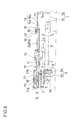
cam slider 8 is made to slide in the direction along arrow e. Thecam mechanism 9 makes thetraverse chassis 6 rotate in the direction along arrow c. And, as shown inFIG. 6 , the disk Da or Db is lifted by the turn table 3, to be clamped by the turn table 3 and theclamper 11. - Simultaneously, the
cam slider 8 is made to engage with theflap 27, and thereby, theflap 27 rotates about thepivot shaft 28 against theholddown spring 29 to move away from the disk Da or Db. Thestopper piece 27a of theflap 27 closes the disk insertion slot 2. And, the disk stopper 16 slightly moves in the direction along arrow a, to move away from the disk Da or Db. - Then subsequently, by the
spindle motor 4, via theturntable 3, the disk Da or Db is made to rotate at a high speed, and theoptical pickup 5 moves in a diameter direction of the disk Da or Db. By means of theoptical pickup 5, information recorded in the disk Da or Db is read out. - The
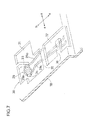
holddown spring 29 includes a pair of right and left holddown springs which are fitted tospring seats 30 at both opposing sides in the front part of thelid panel 1B, as shown inFIGS. 7 and8 . - The
spring seats 30 each have first andsecond openings lid panel 1B with a predetermined distance therebetween in the directions along arrows a and b. Asupport frame 33 extends from a front edge of the first opening 31 in a zigzag manner toward theflap 27, and at an end of thesupport frame 33, a cylindrical-column-shaped support shaft 34 is integrally formed to project in directions along arrows e and f in parallel with thelid panel 1B. Between the first andsecond openings partition panel 35. From a side edge of the second opening 32, aprojection piece 36 is integrally formed to project therefrom into thesecond opening 32. A part of theprojection piece 36 from a center thereof to an end thereof is bent toward theflap 27 side. - The
holddown spring 29 is formed of acoil portion 29a wound three or four times and tworod portions coil portion 29a. - A description will be given of a procedure of fitting the
holddown spring 29. With thelid panel 1B put upside down, thecoil portion 29a of theholddown spring 29 is fitted onto thesupport shaft 34. Then, with onerod portion 29b in contact with thepartition panel 35, theother rod portion 29c is put on theprojection piece 36 and temporarily fixed (see a phantom line inFIG. 7 ). Then subsequently, after theflap 27 is fitted to thelid panel 1B, theother rod portion 29c is taken off from theprojection piece 36 and brought into contact with the flap 27 (seeFIG. 5 ). Incidentally, a related technique is described inPatent Literature 1 listed below. - Patent Literature 1:
JP-A-2007-80337 - In the above-described conventional configuration, the
support shaft 34 is disposed parallel and close to thelid panel 1B. Thus, in manually fitting thecoil portion 29a of theholddown spring 29 onto thesupport shaft 34, a finger of an operator is liable to be caught by thelid panel 1B, and this increases time and trouble of the fitting operation, making the operation so troublesome. - Besides, since the
support shaft 34 is cylindrical-column-shaped, in fitting theflap 27 to thelid panel 1B, an instrument or a finger of an operator is liable to be caught by thecoil portion 29a to cause thecoil portion 29a to come off from thesupport shaft 34. - In view of the above-discussed conventionally experienced inconveniences, an object of the present invention is to provide a disk device that allows an easy operation of fitting a holddown spring for a flap, and that allows the holddown spring to be securely maintained in a fitted state.
- To achieve the above object, a disk device according to the present invention includes a loader chassis that includes a disk insertion slot formed in a front surface thereof, a conveyance roller that conveys a disk slotted in through the disk insertion slot into the loader chassis, a flap that holds the disk in cooperation with the conveyance roller, and a holddown spring that presses the flap toward the conveyance roller. Here, the loader chassis includes: a chassis main body; and a lid panel where a spring seat to which the holddown spring is fitted is provided, the lid panel is provided with an opening, the spring seat includes an L-shaped frame that includes a support panel that is integrally formed at an edge of the opening, and a support shaft panel that is bent at a right angle from an end of the support panel, the support panel is bent at a root part thereof such that the L-shaped frame is raised toward the flap side, the support shaft panel includes a stopper portion that projects toward the flap side from a flap-side edge at an end of the support shaft panel, and a support shaft main body between the stopper portion and the support panel, a sloped guide edge is formed by cutting an end side of a lid panel-side edge of the support shaft panel, and the holddown spring includes a coil portion that is fitted, along the sloped guide edge, onto the support shaft main body, a first rod portion that extends from one end of the coil portion to engage with the lid portion, and a second rod portion that extends from another end of the coil portion to be in contact with the flap.
- In this configuration, in regard to manually fitting the coil portion of the holddown spring onto the support shaft main body of the support shaft panel, the sloped guide edge formed at an end of the support shaft panel extends in an oblique direction away from the lid panel. Thus, it is possible to easily fit the coil portion of the holddown spring along the sloped guide edge onto the support shaft main body. Furthermore, in regard to fitting the flap to the lid panel, the stopper portion is provided at an end of the support shaft panel to deal with a case where an instrument or an operator finger is caught by the coil portion of the holddown spring. Thus, the coil portion does not come off from the support shaft panel, which contributes to efficient operation of fitting the flap.
- In the above-described disk device, a width of the support shaft main body may be set wider than a width of the coil portion, and a projection distance of the stopper portion may be set larger than an outer diameter of a wire member forming the holddown spring. The L-shaped frame may be obtained as a portion that is left after cutting the lid panel to form the opening. In the above-described desk device, the stopper portion may include a sloped side edge at an edge thereof on the support shaft main body side, and the sloped side edge may be sloped at a predetermined slope angle with respect to the support shaft main body.
- Further features and advantages of the present invention will be made clear in the following description of embodiments.
- According to the present invention, it is possible to provide a disk device that allows an easy operation of fitting a holddown spring for a flap, and that allows the holddown spring to be securely maintained in the fitted state.
-
-
FIG. 1 is a perspective view of a relevant part of a disk device as one embodiment of the present invention; -
FIG. 2 is a transverse sectional view of the relevant part; -
FIG. 3A is a transverse sectional view illustrating a fitted state of a holddown spring; -
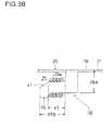
FIG. 3B is a transverse sectional view illustrating a fitted state of the holddown spring; -
FIG. 4 is a plan view showing an unloading state of a conventional example; -
FIG. 5 is a longitudinal sectional view of the unloading state; -
FIG. 6 is a longitudinal sectional view of the unloading state; -
FIG. 7 is a perspective view of the relevant part; and -
FIG. 8 is a transverse sectional view of the relevant part. - Embodiments of the present invention will be described below with reference to the accompanying drawings.
FIGS. 1 ,2 ,3A , and3B show a relevant part of a disk device embodying the present invention. This is a Blu-ray Disc recorder (or player) provided with a disk slot loading mechanism. Aspring seat 30 has an L-shapedframe 38 obtained as a portion that is left after cutting ametal lid panel 1B to form afirst opening 31. The L-shapedframe 38 includes asupport panel 38A that is integrally formed at an edge of thefirst opening 31 and asupport shaft panel 38B that is bent at a right angle from an end of thesupport panel 38A. A base part of thesupport panel 38A is bent, so that the L-shapedframe 38 is pulled to rise toward theflap 27. At an end of thesupport shaft panel 38B, astopper portion 39 is provided that projects from a flap-side edge 40A toward theflap 27 side. A part of thesupport shaft panel 38B between thestopper portion 39 and thesupport panel 38A is a support shaftmain body 40 that supports acoil portion 29a of aholddown spring 29. Configurations other than the above are substantially the same as those shown inFIGS. 4 to 8 . Thus, in the following descriptions, portions that are the same as those shown in the drawings will be denoted by the same symbols, and descriptions thereof will be omitted. - As shown in
FIGS. 1 ,2 ,3A , and3B , a side edge of thestopper portion 39 opposed to the support shaftmain body 40 is sloped by a predetermined slope angle α (for example 45°), and thereby, asloped side edge 39a is formed. A part of a lid panel-side edge 40B of thesupport shaft panel 38B, the part extending from the support shaftmain body 40 to an end of thesupport shaft panel 38B, is cut to form a slopedguide edge 41 that is sloped at a predetermined slope angle β (for example, 30°). - As shown in
FIG. 2 , the flap-side edge 40A and the lid panel-side edge 40B of the support shaftmain body 40 are formed parallel to each other. A width h1 of the support shaftmain body 40 is set larger than a width h2 of thecoil portion 29a. A projection distance t1 of thestopper portion 39 is set larger than an outer diameter t2 of a wire member forming theholddown spring 29. - A description will be given of a procedure of fitting the
holddown spring 29. With thelid panel 1B put upside down, as shown inFIG. 3A , thecoil portion 29a of theholddown spring 29 is moved along the slopedside edge 39a of thestopper portion 39 and the slopedguide edge 41 into contact with the end of thesupport shaft panel 38B. Then, as shown inFIG. 3B , thecoil portion 29a is fitted onto the support shaftmain body 40. Then subsequently, as shown inFIG. 1 , onerod portion 29b is brought into contact with apartition panel 35, and theother rod portion 29c is put on aprojection piece 36 and temporarily fixed. Thereafter, theflap 27 is fitted to thelid panel 1B, and then, theother rod portion 29c is removed from theprojection piece 36 and brought into contact with the flap 27 (seeFIG. 5 ). - According to the above configuration, as shown in
FIG. 3A , in regard to manually fitting thecoil portion 29a of theholddown spring 29 onto the support shaftmain body 40 of thesupport shaft panel 38B, the slopedside edge 39a of thestopper portion 39 and the slopedguide edge 41 formed at the end of thesupport shaft panel 38B extend in an oblique direction away from thelid panel 1B. This makes it easy to move thecoil portion 29a of theholddown spring 29 along the slopedside edge 39a of thestopper portion 39 and the slopedguide edge 41 to fit thecoil portion 29a onto the support shaftmain body 40 of thesupport shaft panel 38B. - As shown in
FIG. 2 , the projection distance t1 of thestopper portion 39 that is integrally formed to project from the end of thesupport shaft panel 38B is set larger than the outer diameter t2 of the wire member that forms theholddown spring 29. Furthermore, the width h1 of the support shaftmain body 40 is set larger than the width h2 of thecoil portion 29a. Thus, as shown inFIG. 3B , even if an instrument or a finger of an operator is caught by thecoil portion 29a fitted onto the support shaftmain body 40 in fitting theflap 27 to thelid panel 1B, so that an excessive load M is applied to thecoil portion 29a, thecoil portion 29a never comes off from the support shaftmain body 40. Thus, it is possible to securely maintain theholddown spring 29 fitted to thespring seat 30. Moreover, it is possible to efficiently perform the operation of fitting theflap 27. - As shown in
FIG.1 , the L-shapedframe 38 including thesupport panel 38A and thesupport shaft panel 38B is obtained as a portion that is left after themetal lid panel 1B is cut to form thefirst opening 31. Thus, the number of components is not increased by forming the L-shapedframe 38, and the production cost can be reduced. - As discussed above, in the disk device of the present embodiment, a disk insertion slot is formed in the front surface of a loader chassis including a chassis main body and a lid panel, a traverse chassis having a turntable and an optical pickup mounted thereon is disposed inside the loader chassis, a conveyance roller is disposed in a front part of the chassis main body to be opposite to the disk insertion slot, the conveyance roller being rotatable both forward and backward, a flap is disposed on a rear surface side of the lid panel to be opposite to the conveyance roller, the flap being rotatable about a pivot shaft, a holddown spring that presses the flap toward the conveyance roller is fitted to a spring seat of the lid panel, a disk slotted in through the disk insertion slot is held by the conveyance roller and the flap to be conveyed into the loader chassis, the disk is rotated at a high speed by the turntable, and the optical pickup reads out information recorded on the disk. Here, the disk device is characterized in that the spring seat has an L-shaped frame obtained as a portion that is left after cutting the metal lid panel to form an opening, that the L-shaped frame includes a support panel that is integrally formed at an edge of the opening and a support shaft panel that is bent at a right angle from an end of the support panel, that a root part of the support panel is bent, so that the L-shaped frame is pulled to rise toward the flap, that a stopper portion is provided that projects from an end of the support shaft panel at a flap-side edge toward the flap side, that a part of the support shaft panel between the stopper portion and the support panel is a support shaft main body that supports a coil portion of the holddown spring, that a part of a lid panel-side edge of the support shaft panel, the part extending from the support shaft main body to an end of the support shaft panel, is cut to form a sloped guide edge, and that the coil portion of the holddown spring is moved along the sloped guide edge and fitted onto the support shaft main body, and that two rod portions extending from both ends of the coil portion of the holddown spring are respectively engaged with the lid panel and the flap.
- With this configuration, in regard to manually fitting the coil portion of the holddown spring onto the support shaft main body of the support shaft panel, the sloped guide edge formed at an end of the support shaft panel extends in an oblique direction away from the lid panel. Thus, it is possible to easily fit the coil portion of the holddown spring along the sloped guide edge onto the support shaft main body.
- Furthermore, in regard to fitting the flap to the lid panel, the stopper portion is provided at an end of the support shaft panel to deal with a case where an instrument or a finger of an operator is caught by the coil portion of the holddown spring. Thus, the coil portion does not come off from the support shaft panel, and this contributes to efficient operation of fitting the flap.
- Furthermore, the L-shaped frame including the support panel and the support shaft panel is obtained as a portion that is left after cutting the metal lid panel to form the opening. Thus, the number of components is not increased by forming the L-shaped frame. Moreover, it is possible to reduce production cost.
- Moreover, the disk device of the present embodiment is characterized in that the support shaft main body has a wider width than the coil portion, and the projection distance of the stopper portion is set larger than the outer diameter of the wire member that forms the holddown spring.
- With this configuration, even if, with the coil portion of the holddown spring fitted onto the support shaft main body of the support shaft panel, an excessive load is applied to the coil portion by an instrument or a finger of an operator in a direction of removing the coil portion from the support shaft panel, the width of the support shaft main body is set larger than that of the coil portion, and furthermore, the projection distance of the stopper portion is set larger than the outer diameter of the wire member forming the holddown spring, and thus, the coil portion never comes off from the support shaft main body, and it is possible to securely maintain the holddown spring fitted to the spring seat.
-
- 1
- loader chassis
- 1A
- main body of loader chassis
- 1B
- lid panel of loader chassis
- 2
- disk insertion slot
- 3
- turntable
- 5
- optical pickup
- 30
- spring seat
- 38
- L-shape frame
- 38A
- support panel of L-shape frame
- 38B
- support shaft panel of L-shape frame
- 39
- stopper portion
- 40
- main body of support shaft
- 40A
- flap-side edge of main body of support shaft
- 40B
- lid panel-side edge of main body of support shaft
- 41
- sloped guide edge
- Da
- small disk
- Db
- large disk
- a
- slot in
Claims (8)
- A disk device comprising:a loader chassis that includes a disk insertion slot formed in a front surface thereof;a conveyance roller that conveys a disk slotted in through the disk insertion slot into the loader chassis;a flap that holds the disk in cooperation with the conveyance roller; anda holddown spring that presses the flap toward the conveyance roller,whereinthe loader chassis includes:a chassis main body; anda lid panel where a spring seat to which the holddown spring is fitted is provided,the lid panel is provided with an opening;the spring seat includes an L-shaped frame that includes:a support panel that is integrally formed at an edge of the opening; anda support shaft panel that is bent at a right angle from an end of the support panel,the support panel is bent at a root part thereof such that the L-shaped frame is raised toward the flap side,the support shaft panel includes:a stopper portion that projects toward the flap side from a flap-side edge at an end of the support shaft panel; anda support shaft main body between the stopper portion and the support panel,a sloped guide edge is formed by cutting an end side of a lid panel-side edge of the support shaft panel, andthe holddown spring includes:a coil portion that is fitted, along the sloped guide edge, onto the support shaft main body;a first rod portion that extends from one end of the coil portion to engage with the lid portion; anda second rod portion that extends from another end of the coil portion to be in contact with the flap.
- The disk device of claim 1,
wherein
a width of the support shaft main body is set wider than a width of the coil portion, and
a projection height of the stopper portion is larger than an outer diameter of a wire member that forms the holddown spring. - The disk device of claim 1,
wherein
the L-shaped frame is obtained as a portion that is left after cutting the lid panel to form the opening. - The disk device of claim 2,
wherein
the L-shaped frame is obtained as a portion that is left after cutting the lid panel to form the opening. - The disk device of claim 1,
wherein
the stopper portion includes a sloped side edge formed at an edge thereof on the support shaft main body side, and
the sloped side edge is sloped at a predetermined slope angle with respect to the support shaft main body. - The disk device of claim 2,
wherein
the stopper portion includes a sloped side edge formed at an edge thereof on the support shaft main body side, and
the sloped side edge is sloped at a predetermined slope angle with respect to the support shaft main body. - The disk device of claim 3,
wherein
the stopper portion includes a sloped side edge formed at an edge thereof on the support shaft main body side, and
the sloped side edge is sloped at a predetermined slope angle with respect to the support shaft main body. - The disk device of claim 4,
wherein
the stopper portion includes a sloped side edge formed at an edge thereof on the support shaft main body side, and
the sloped side edge is sloped at a predetermined slope angle with respect to the support shaft main body.
Applications Claiming Priority (2)
| Application Number | Priority Date | Filing Date | Title |
|---|---|---|---|
| JP2010246720A JP2012099185A (en) | 2010-11-02 | 2010-11-02 | Disk drive |
| PCT/JP2011/075037 WO2012060314A1 (en) | 2010-11-02 | 2011-10-31 | Disk device |
Publications (1)
| Publication Number | Publication Date |
|---|---|
| EP2637168A1 true EP2637168A1 (en) | 2013-09-11 |
Family
ID=46024427
Family Applications (1)
| Application Number | Title | Priority Date | Filing Date |
|---|---|---|---|
| EP11837964.3A Withdrawn EP2637168A1 (en) | 2010-11-02 | 2011-10-31 | Disk device |
Country Status (5)
| Country | Link |
|---|---|
| US (1) | US20130227593A1 (en) |
| EP (1) | EP2637168A1 (en) |
| JP (1) | JP2012099185A (en) |
| CN (1) | CN103180905A (en) |
| WO (1) | WO2012060314A1 (en) |
Family Cites Families (10)
| Publication number | Priority date | Publication date | Assignee | Title |
|---|---|---|---|---|
| JPH02140764U (en) * | 1989-04-27 | 1990-11-26 | ||
| JPH03106756U (en) * | 1990-02-19 | 1991-11-05 | ||
| JPH07240056A (en) * | 1994-02-28 | 1995-09-12 | Mitsubishi Electric Corp | Medium elevating mechanism of disk device |
| RU2150562C1 (en) * | 1996-03-29 | 2000-06-10 | Херманн Кг Брокхаген | Ceiling sectional gate |
| JP3325820B2 (en) * | 1997-11-29 | 2002-09-17 | タナシン電機株式会社 | Disk transport device of disk player |
| JP3106756U (en) * | 2004-07-23 | 2005-01-20 | 船井電機株式会社 | Television with disc playback function and disc playback device |
| JP2007066430A (en) * | 2005-08-31 | 2007-03-15 | Orion Denki Kk | Guide shaft holding mechanism and optical disk drive provided with guide shaft holding mechanism |
| JP3892021B1 (en) * | 2005-09-08 | 2007-03-14 | 三菱電機株式会社 | Disc loading device and disc device |
| JP3862733B1 (en) | 2005-09-13 | 2006-12-27 | 三菱電機株式会社 | Disk device and disk loading mechanism |
| JP2010080020A (en) * | 2008-09-29 | 2010-04-08 | Orion Denki Kk | Storage medium conveyance mechanism in storage medium reproducing device or storage medium recording/reproducing device |
-
2010
- 2010-11-02 JP JP2010246720A patent/JP2012099185A/en active Pending
-
2011
- 2011-10-31 EP EP11837964.3A patent/EP2637168A1/en not_active Withdrawn
- 2011-10-31 WO PCT/JP2011/075037 patent/WO2012060314A1/en not_active Ceased
- 2011-10-31 US US13/882,805 patent/US20130227593A1/en not_active Abandoned
- 2011-10-31 CN CN2011800523009A patent/CN103180905A/en active Pending
Non-Patent Citations (1)
| Title |
|---|
| See references of WO2012060314A1 * |
Also Published As
| Publication number | Publication date |
|---|---|
| CN103180905A (en) | 2013-06-26 |
| US20130227593A1 (en) | 2013-08-29 |
| WO2012060314A1 (en) | 2012-05-10 |
| JP2012099185A (en) | 2012-05-24 |
Similar Documents
| Publication | Publication Date | Title |
|---|---|---|
| US7627875B2 (en) | Disk drive | |
| JP3890660B2 (en) | Disc recording and / or playback device | |
| US20130227593A1 (en) | Disk device | |
| US7793314B2 (en) | Disk drive device with arm for disc conveyance | |
| US20010021156A1 (en) | Disk device having disk transferring mechanism capable of shortening disk replacement time--in its place | |
| EP1087389A1 (en) | Disc unit | |
| US8255935B2 (en) | Slot-in type disk apparatus in which a disk is directly operated by a lever | |
| US6434102B1 (en) | Disk device | |
| US20090293077A1 (en) | Optical disk device | |
| GB2052833A (en) | Cassette tape player | |
| US8347324B2 (en) | Disc identifying device | |
| JP2003208748A (en) | Disk unit loading mechanism | |
| US4344098A (en) | Cassette tape player | |
| JP4785875B2 (en) | Optical pickup guide shaft positioning device | |
| US8087040B2 (en) | Slot-in type disk drive | |
| JP2003217216A (en) | Auto loading mechanism of disk unit | |
| JPWO2000048187A1 (en) | Disk device | |
| JP4184285B2 (en) | Disk unit | |
| JP3891216B2 (en) | Disc recording and / or playback device | |
| US20090235287A1 (en) | Conveyance Device and Recording Meduim Drive Device | |
| JP5125966B2 (en) | Disk unit | |
| JP4848328B2 (en) | Disk unit | |
| JP3757533B2 (en) | Disc recording and / or playback device | |
| JPH1040562A (en) | Optical disk drive | |
| JPH11238277A (en) | Optical disk drive |
Legal Events
| Date | Code | Title | Description |
|---|---|---|---|
| PUAI | Public reference made under article 153(3) epc to a published international application that has entered the european phase |
Free format text: ORIGINAL CODE: 0009012 |
|
| 17P | Request for examination filed |
Effective date: 20130418 |
|
| AK | Designated contracting states |
Kind code of ref document: A1 Designated state(s): AL AT BE BG CH CY CZ DE DK EE ES FI FR GB GR HR HU IE IS IT LI LT LU LV MC MK MT NL NO PL PT RO RS SE SI SK SM TR |
|
| DAX | Request for extension of the european patent (deleted) | ||
| STAA | Information on the status of an ep patent application or granted ep patent |
Free format text: STATUS: THE APPLICATION HAS BEEN WITHDRAWN |
|
| 18W | Application withdrawn |
Effective date: 20140409 |