EP2637065A2 - Print medium feeding apparatus with electrode in endless belt - Google Patents
Print medium feeding apparatus with electrode in endless belt Download PDFInfo
- Publication number
- EP2637065A2 EP2637065A2 EP13157722.3A EP13157722A EP2637065A2 EP 2637065 A2 EP2637065 A2 EP 2637065A2 EP 13157722 A EP13157722 A EP 13157722A EP 2637065 A2 EP2637065 A2 EP 2637065A2
- Authority
- EP
- European Patent Office
- Prior art keywords
- electrodes
- paper feed
- voltage
- endless belt
- paper
- Prior art date
- Legal status (The legal status is an assumption and is not a legal conclusion. Google has not performed a legal analysis and makes no representation as to the accuracy of the status listed.)
- Withdrawn
Links
- 230000004044 response Effects 0.000 claims abstract description 18
- 230000008859 change Effects 0.000 claims abstract description 8
- 230000010365 information processing Effects 0.000 claims description 13
- 238000000034 method Methods 0.000 claims description 9
- 230000001105 regulatory effect Effects 0.000 description 10
- 230000006870 function Effects 0.000 description 8
- 230000008569 process Effects 0.000 description 7
- 238000003860 storage Methods 0.000 description 6
- 238000007639 printing Methods 0.000 description 5
- 239000004065 semiconductor Substances 0.000 description 4
- 230000005540 biological transmission Effects 0.000 description 3
- 238000001514 detection method Methods 0.000 description 3
- 230000002093 peripheral effect Effects 0.000 description 3
- 238000004891 communication Methods 0.000 description 2
- 238000005516 engineering process Methods 0.000 description 2
- 230000003287 optical effect Effects 0.000 description 2
- 230000009467 reduction Effects 0.000 description 2
- 238000005520 cutting process Methods 0.000 description 1
- 238000012840 feeding operation Methods 0.000 description 1
- 239000004973 liquid crystal related substance Substances 0.000 description 1
- 238000004519 manufacturing process Methods 0.000 description 1
- 238000012986 modification Methods 0.000 description 1
- 230000004048 modification Effects 0.000 description 1
- 238000004080 punching Methods 0.000 description 1
- 230000003252 repetitive effect Effects 0.000 description 1
Images






Classifications
-
- B—PERFORMING OPERATIONS; TRANSPORTING
- B65—CONVEYING; PACKING; STORING; HANDLING THIN OR FILAMENTARY MATERIAL
- B65H—HANDLING THIN OR FILAMENTARY MATERIAL, e.g. SHEETS, WEBS, CABLES
- B65H3/00—Separating articles from piles
- B65H3/18—Separating articles from piles using electrostatic force
-
- B—PERFORMING OPERATIONS; TRANSPORTING
- B65—CONVEYING; PACKING; STORING; HANDLING THIN OR FILAMENTARY MATERIAL
- B65H—HANDLING THIN OR FILAMENTARY MATERIAL, e.g. SHEETS, WEBS, CABLES
- B65H7/00—Controlling article feeding, separating, pile-advancing, or associated apparatus, to take account of incorrect feeding, absence of articles, or presence of faulty articles
- B65H7/18—Modifying or stopping actuation of separators
-
- G—PHYSICS
- G03—PHOTOGRAPHY; CINEMATOGRAPHY; ANALOGOUS TECHNIQUES USING WAVES OTHER THAN OPTICAL WAVES; ELECTROGRAPHY; HOLOGRAPHY
- G03G—ELECTROGRAPHY; ELECTROPHOTOGRAPHY; MAGNETOGRAPHY
- G03G15/00—Apparatus for electrographic processes using a charge pattern
- G03G15/65—Apparatus which relate to the handling of copy material
- G03G15/6502—Supplying of sheet copy material; Cassettes therefor
- G03G15/6511—Feeding devices for picking up or separation of copy sheets
-
- B—PERFORMING OPERATIONS; TRANSPORTING
- B65—CONVEYING; PACKING; STORING; HANDLING THIN OR FILAMENTARY MATERIAL
- B65H—HANDLING THIN OR FILAMENTARY MATERIAL, e.g. SHEETS, WEBS, CABLES
- B65H2404/00—Parts for transporting or guiding the handled material
- B65H2404/20—Belts
- B65H2404/25—Driving or guiding arrangements
-
- B—PERFORMING OPERATIONS; TRANSPORTING
- B65—CONVEYING; PACKING; STORING; HANDLING THIN OR FILAMENTARY MATERIAL
- B65H—HANDLING THIN OR FILAMENTARY MATERIAL, e.g. SHEETS, WEBS, CABLES
- B65H2511/00—Dimensions; Position; Numbers; Identification; Occurrences
- B65H2511/10—Size; Dimensions
-
- B—PERFORMING OPERATIONS; TRANSPORTING
- B65—CONVEYING; PACKING; STORING; HANDLING THIN OR FILAMENTARY MATERIAL
- B65H—HANDLING THIN OR FILAMENTARY MATERIAL, e.g. SHEETS, WEBS, CABLES
- B65H2511/00—Dimensions; Position; Numbers; Identification; Occurrences
- B65H2511/20—Location in space
- B65H2511/21—Angle
- B65H2511/212—Rotary position
-
- B—PERFORMING OPERATIONS; TRANSPORTING
- B65—CONVEYING; PACKING; STORING; HANDLING THIN OR FILAMENTARY MATERIAL
- B65H—HANDLING THIN OR FILAMENTARY MATERIAL, e.g. SHEETS, WEBS, CABLES
- B65H2515/00—Physical entities not provided for in groups B65H2511/00 or B65H2513/00
- B65H2515/70—Electrical or magnetic properties, e.g. electric power or current
Definitions
- the disclosures herein relate to a print medium feeding apparatus, an image forming apparatus, and a print medium feeding system.
- An image forming apparatus such as a printer or a copier feeds paper sheets one by one to an image forming unit by separating a paper sheet from a stack of paper sheets stored in a sheet tray, and uses the image forming unit to print an image on the surface of the paper sheet, which is then discharged to outside the apparatus. If multiple paper sheets are fed at a time from the sheet tray, a paper jam may occur along the conveyance path or in the image forming unit, or a print failure may be caused. In order to improve the productivity of the image forming apparatus, there is a need to separate paper sheets one by one from a stack of paper sheets at high speed in a stable manner.
- An electrostatic adherence paper feed technology known in the art uses a plurality of electrodes embedded in an insulating paper feed belt, and applies voltage to the electrodes to polarize a paper sheet surface that is placed in contact with the paper feed belt, thereby causing the paper sheet to adhere to the paper feed belt through an electrostatic force to feed the paper sheet.
- the electrostatic adherence paper feed technology may need to apply a large voltage to the electrodes to create sufficient paper sheet adherence when the paper sheet to be fed is larger than the paper feed belt.
- the paper feed belt is the same size as the size of the largest sheet among paper sheets to be fed, voltage applied to the entirety of the paper feed belt at the time of feeding a small-sized paper sheet may result in needless consumption of electric power.
- a print medium feeding apparatus that can feed a medium by the use of an appropriate amount of electric power responsive to the size of the medium.
- a print medium feeding apparatus includes an endless belt disposed to face stacked media and configured to rotate, the endless belt divided into sections having electrodes, respectively, fixed terminals configured to be in contact with two or more of the electrodes while the two or more of the electrodes are passing through a position facing the media as the electrodes are moved by rotation of the endless belt, a voltage applying unit connected to the fixed terminals and configured to apply voltage to the two or more of the electrodes that are in contact with the fixed terminals, a connection unit configured to make and break a connection between the voltage applying unit and at least one of the fixed terminals, and a switching unit configured to change a state of the connection of the connection unit in response to size of the media.
- a print medium feeding apparatus that can feed a medium by use of an appropriate amount of electric power responsive to the size of the medium.
- Fig. 11 is a drawing illustrating an example of the hardware configuration of the image forming system according to the fourth embodiment.
- Fig. 1 is a drawing illustrating an example of the appearance of an image forming apparatus 200 that is provided with a paper feed apparatus according to a first embodiment.
- the image forming apparatus 200 includes an image forming apparatus main section 201, an automatic document feeder (ADF) 202, a finisher 203 having a stapler and a shift tray, a duplex-printing buffer/flipper unit 204, an extended paper feed tray 205, a one-bin discharge tray 207, an insert feeder 208, and so on.
- ADF automatic document feeder
- the image forming apparatus main section 201 includes a scanner unit, an image forming unit, a developer unit, a fuser unit, and a paper feed apparatus, etc., accommodated therein, and prints an image on the surface of a paper sheet fed from the paper feed apparatus.
- the image forming apparatus main section 201 may use an electrophotographic process to print an image on the surface of a paper sheet.
- the process of forming an image may be a different process such as an inkjet process. Further, it does not matter whether the process is a monochrome process or a full color process.
- Fig. 2 is a drawing illustrating an example of the schematic configuration of a paper feed apparatus 100 and a paper feed cassette 9 according to the first embodiment.
- the paper feed apparatus 100 includes a paper feed belt 1, a drive roller 141, a driven roller 142, and a high-voltage power supply 121.
- the paper feed belt 1 is an endless belt having a plurality of electrodes embedded therein that are covered with an insulating layer.
- the paper feed belt 1 is looped around the drive roller 141 and the driven roller 142.
- the drive roller 141 is rotated by a drive unit (not shown) to rotate the paper feed belt 1.
- the driven roller 142 is rotated by the paper feed belt 1 that is rotated by the drive roller 141.
- the high-voltage power supply 121 applies voltage to the electrodes in the paper feed belt 1 to polarize the surface of a paper sheet P coming in contact with the paper feed belt 1, thereby causing the paper sheet P to adhere to the paper feed belt 1.
- the paper feed cassette 9 storing paper sheets P includes a sheet-width regulating guide 4, a sheet-rear-end regulating plate 5, a bottom plate 6, a fan 7, an optical sensor 8, a conveyor sensor 10, and a conveyor roller 11.
- the sheet-width regulating guide 4 and the sheet-rear-end regulating plate 5 secure the paper sheets P in their place and also detect the size of the paper sheets P upon the paper sheets P being set.
- the bottom plate 6 elevates to such a height that the top of the stored paper sheets P can be detected by the optical sensor 8, thereby raising the paper sheets P to the position at which paper feeding can be performed by the paper feed apparatus 100.
- the fan 7 blows air into a space over the stacked paper sheets P to flip a sheet, thereby causing the topmost paper sheet P to come in contact with the paper feed belt 1.
- the paper sheet P may come in contact with the paper feed belt 1 while voltage is applied to the embedded electrodes. When this happens, the surface of the paper sheet P polarizes, and thus adheres to the paper feed belt 1. Rotation of the paper feed belt 1 then causes the paper sheet P to be conveyed to outside the paper feed cassette 9.
- the conveyor sensor 10 detects the paper sheet P that is fed by the paper feed belt 1 to a conveyor path. Upon the conveyor sensor 10 detecting the paper sheet P, the paper feed apparatus 100 deactivates the high-voltage power supply 121 to stop the adherence and conveyance of the paper sheet P.
- the conveyor roller 11 conveys the paper sheet P to the image forming unit or the like situated at the next stage as the paper sheet P is fed from the paper feed cassette 9 by the paper feed belt 1 of the paper feed apparatus 100.
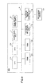
- Fig. 3 is a drawing illustrating an example of the hardware configuration of the paper feed apparatus 100 according to the first embodiment.
- the paper feed apparatus 100 includes, in addition to the paper feed belt 1, the high-voltage power supply 121, and so on, a CPU (Central Processing Unit) 171, an HDD (Hard Disk Drive) 172, a ROM (Read Only Memory) 173, a RAM (Random Access Memory) 174, a network interface unit 175, a recording medium interface unit 176, etc., which are connected to each other through a bus B.
- a CPU Central Processing Unit
- HDD Hard Disk Drive
- ROM Read Only Memory
- RAM Random Access Memory
- the CPU 171 is a computing unit that performs control operations, arithmetic operations, and data processing by executing programs stored in the ROM 173 and the RAM 174.
- the CPU 171 performs overall control of the apparatus by executing programs, and also serves as a switchover unit to select the electrodes of the paper feed belt 1 to which the high-voltage power supply 121 applies voltage.
- the HDD 172 is a nonvolatile storage device to store various programs and data.
- the stored programs and data include an OS (Operating System) and application programs providing various functions.
- the ROM 173 is a nonvolatile semiconductor memory (storage device) that can retain stored data even when the power is switched off.
- the RAM 174 is a volatile semiconductor memory (storage device) that temporarily stores programs and data.
- the network interface unit 175 is an interface with peripheral devices having a communication function that are connected through a network such as a LAN (Local Area Network) or WAN (Wide Area Network), which is implemented by use of wired and/or wireless data transmission lines.
- a network such as a LAN (Local Area Network) or WAN (Wide Area Network), which is implemented by use of wired and/or wireless data transmission lines.
- the recording medium interface unit 176 is an interface with a computer-readable recording medium 177 such as a CD-ROM, a flexible disk (FD), a CD-R, a DVD (Digital Versatile Disk), or the like, which is connected through a data transmission line such as a USB (Universal Serial Bus).
- a computer-readable recording medium 177 such as a CD-ROM, a flexible disk (FD), a CD-R, a DVD (Digital Versatile Disk), or the like, which is connected through a data transmission line such as a USB (Universal Serial Bus).
- a predetermined program is stored in the recording medium 177.
- the program stored in the recording medium 177 is installed in the paper feed apparatus 100 via the recording medium interface unit 176.
- the installed program is ready to be executed by the CPU 171.
- the CPU 171, the HDD 172, the ROM 173, the RAM 174 and the like may be shared with one or more other units such as the image forming apparatus main section 201.
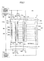
- Fig. 4 is a drawing illustrating an example of the configuration of the paper feed apparatus 100 according to the first embodiment.
- the paper feed apparatus 100 includes, in addition to the paper feed belt 1, the drive roller 141 and the driven roller 142, the high-voltage power supply 121, a control unit 122, etc.
- the paper feed apparatus 100 feeds a paper sheet taken from the paper feed cassette 9.
- the paper feed belt 1 is looped around the drive roller 141 and the driven roller 142.
- the paper feed belt 1 is rotated in a clockwise direction by the drive roller 141 that rotates in the direction indicated by an arrow.
- the distance between the drive roller 141 and the driven roller 142 is equivalent to the longitudinal length of an A3 paper sheet.
- the distance between the drive roller 141 and the driven roller 142 may be adaptively set in response to the size of the paper sheet P that is to be fed.
- the paper feed belt 1 has four sections A through D arranged in the rotational direction thereof.
- the four sections A through D have four electrodes 101 through 104, respectively, embedded therein.
- Figs. 5A and 5B are drawings illustrating an example of the configuration of the paper feed belt 1 of the paper feed apparatus 100 according to the first embodiment.
- Fig. 5A is a plan view of the section A and part of the section B of the paper feed belt 1 viewed from the inner side of the paper feed belt 1.
- Fig. 5B is a schematic view of the cross-section taken along the line a-a' illustrated in Fig. 5A .
- sections A and B of the paper feed belt 1 have a pair of comb-shaped electrodes 101a and 101b and a pair of comb-shaped electrodes 102a and 102b, respectively, which are arranged such that the teeth of one electrode extend in the direction perpendicular to the rotational direction of the paper feed belt 1 into the spaces between the teeth of the other electrode.
- the remaining sections C and D are arranged such that the teeth of one electrode extend in the direction perpendicular to the rotational direction of the paper feed belt 1 into the spaces between the teeth of the other electrode.
- the electrode 101 refers to the pair of electrodes 101a and 101b, and the same applies with respect to each of the remaining electrodes 102 through 104.
- the electrode 101 is covered with an insulating layer 190, except for areas corresponding to openings 111a and 111b of the insulating layer 190 that are situated near the side ends of the paper feed belt 1. The same also applies in the case of the remaining electrodes 102 through 104.
- the side ends of electrode 101 near the side ends of the paper feed belt 1 are exposed through the openings 111a and 111b, respectively, toward the inner side of the paper feed belt 1. The same also applies in the case of the remaining electrodes 102 through 104.
- each of the electrodes 101 through 104 exposed through the openings receive a voltage applied thereto.
- the surface of the paper feed belt 1 is made to exert an adhering force to attract a paper sheet P. Because the electrodes 101 through 104 are covered with the insulating layer, no electric charge moves between the electrodes. Voltage control may be performed such that different voltages are applied to the electrodes 101 through 104.
- roller-shaped, rotatable fixed terminals 131 through 134 are disposed that are in contact with the side ends of the electrodes 101 through 104 exposed through the openings.
- the fixed terminal 131 disposed at the position facing the paper feed cassette 9 (not shown) is directly connected to the high-voltage power supply 121.
- the fixed terminal 132 is connected through a relay 151 to the high-voltage power supply 121.
- the fixed terminals 133 and 134 are connected to ground. Alternative arrangement may be such that the fixed terminals 133 and 134 are not connected to ground.
- the fixed terminals 131 are arranged at such intervals that one electrode arranged in one section of the paper feed belt 1 does not come in contact with two fixed terminals simultaneously.
- the relay 151 is a connecting unit situated between the high-voltage power supply 121 and the fixed terminal 132.
- the relay 151 is controlled by the control unit 122 that serves as a switchover unit for changing the state of connection of the relay 151, thereby connecting the fixed terminal 132 either to the high-voltage power supply 121 or to ground.
- the high-voltage power supply 121 applies voltage to those electrodes among the electrodes 101 through 104 that are in contact with either the fixed terminal 131 or the fixed terminal 132 at the time of feeding a paper sheet P, thereby polarizing the surface of the paper sheet P coming in contact with the area of the paper feed belt 1 to which the voltage is applied, and thus causing the paper sheet P to adhere to the paper feed belt 1.
- One of the two comb-shaped electrodes included in each of the electrodes 101 through 104 may receive a positive polarity voltage, and the other may receive a negative polarity voltage.
- one of the two comb-shaped electrodes may be connected to ground.
- the control unit 122 serves as a switchover unit for changing the state of connection of the relay 151 based on information indicative of the size of the paper sheet P, thereby connecting the fixed terminal 132 either to the high-voltage power supply 121 or to ground.
- the control unit 122 obtains the information indicative of the size of the paper sheet P from information entered by a user or from the results of detections made by the sheet-width regulating guide 4 and the sheet-rear-end regulating plate 5 of the paper feed cassette 9.
- the paper sheets P are stored in the paper feed cassette 9, such that they are placed against the inner wall thereof positioned on the same side as the section D.
- control unit 122 obtains information indicative of the size of the paper sheet P from information entered by a user or from the results of detections made by the sheet-width regulating guide 4 and the sheet-rear-end regulating plate 5 of the paper feed cassette 9.
- the paper sheet P stored in the paper feed cassette 9 may be A3 portrait.
- the control unit 122 controls the state of connection of the relay 151 to connect the fixed terminal 132 to the high-voltage power supply 121.
- the high-voltage power supply 121 supplies voltage.
- the paper feed belt 1 is in such a position as illustrated in Fig. 4 , the voltage is applied to the electrode 104 of the section D being in contact with the fixed terminal 131 and to the electrode 103 of the section C being in contact with the fixed terminal 132.
- the paper feed belt 1 rotates, different electrodes successively come in contact with the fixed terminals 131 and 132.
- the two sections of the paper feed belt 1 that face the paper feed cassette 9 always have the electrodes thereof receiving the voltage, thereby exerting an adhering force to attract the paper sheet P.
- the paper sheet P stored in the paper feed cassette 9 may be A4 landscape.
- the control unit 132 controls the state of connection of the relay 151 to connect the fixed terminal 132 to ground.
- the high-voltage power supply 121 supplies voltage.
- the paper feed belt 1 is in such a position as illustrated in Fig. 4 , voltage is applied only to the electrode 104 of the section D being in contact with the fixed terminal 131.
- the paper feed belt 1 rotates, different electrodes successively come in contact with the fixed terminal 131.
- the section of the paper feed belt 1 that faces the paper feed cassette 9 always has the electrode thereof receiving the voltage, thereby exerting an adhering force to attract the paper sheet P.
- control is performed based on the information indicative of the size of a paper sheet P, such that the fixed terminal 132 is connected to the high-voltage power supply 121 when feeding a large-size paper sheet P, and is not connected to the high-voltage power supply 121 when feeding a small-size paper sheet P.
- the large-size paper sheet can be reliably fed, and, also, needless consumption of electric power is avoided by applying voltage to the electrode(s) of the fewest necessary section(s) when feeding the small-size paper sheet P.
- a remaining charge removing power supply 123 may be provided and connected to the fixed terminals 133 and 134.
- the remaining charge removing power supply 123 applies the voltage for removing remaining charge to an electrode that comes in contact with the fixed terminals 133 and 134 after this electrode receives the voltage of the high-voltage power supply 121 while being in contact with the fixed terminal 131 and disconnects from the fixed terminal 131 as the paper feed belt 1 rotates.
- An effective method to remove remaining charge is to apply an alternating voltage to the electrode while making the amplitude of the alternating voltage smaller and smaller.
- the remaining charge removing power supply 123 may thus be preferably an alternating current power supply and a pulse-voltage power supply capable of applying voltages of opposite polarities, and may preferably apply the voltage to the electrode until the amplitude of the voltage reaches 0 V.
- the fixed terminals 132, 133 and 134 are connected either to the remaining charge removing power supply 123 or to ground through relays 151 through 154 whose connection states are controlled by the control unit 122.
- charge may remain in an electrode to which the high-voltage power supply 121 applies high voltage in order to feed a heavy basis weight paper sheet P, for example.
- the control unit 122 connects the remaining charge removing power supply 123 to the fixed terminal to which the high-voltage power supply 121 does not supply voltage, so that an alternating voltage as described above is applied to each electrode to remove remaining charge.
- Voltage applied by the high-voltage power supply 121 to an electrode may be small when feeding a light basis weight paper sheet P. In this case, remaining charge may not be in existence.
- the control unit 122 thus controls the connection state of the relays 151 through 154 such that the fixed terminals not connected to the high-voltage power supply 121 are connected to ground.
- the remaining charge removing power supply 123 is provided to remove charge remaining in each electrode. This arrangement prevents the paper feed belt 1 from exerting a needless adhering force, thereby ensuring a reliable feeding operation of the paper feed apparatus 100.
- the paper feed apparatus 100 of the first embodiment uses the control unit 122, which changes the state of connection of the relay 151 in response to information indicative of the size of a paper sheet P to change the sections to which the high-voltage power supply 121 applies voltage, thereby attracting and feeding the paper sheet P by use of proper electric power responsive to the size of the paper sheet P.
- the control unit 122 changes the state of connection of the relay 151 in response to information indicative of the size of a paper sheet P to change the sections to which the high-voltage power supply 121 applies voltage, thereby attracting and feeding the paper sheet P by use of proper electric power responsive to the size of the paper sheet P.
- the high-voltage power supply 121 may be powered off while feeding is not performed during an interval between paper sheets, which achieves further reduction in power consumption. Moreover, the provision of the remaining charge removing power supply 123 makes it possible to feed a paper sheet P in a more reliable manner.
- the description of the first embodiment has been given with respect to an example in which the paper feed belt 1 is divided into the four sections A through D in a rotational direction.
- the number of divided sections may be two or more.
- the number of sections may be increased to properly cope with an increased variety of paper sheet sizes, and voltage is applied in response to the size of a paper sheet P to feed the paper sheet P by use of proper electric power while reducing needless power consumption.
- the paper feed apparatus 100 of the second embodiment differs from that of the first embodiment in that the paper feed belt 1 is divided into sections in a direction perpendicular to the rotational direction.
- Fig. 7 is a drawing illustrating an example of the configuration of the paper feed apparatus 100 according to the second embodiment.
- the paper feed belt 1 is divided into sections A through C in a direction perpendicular to the rotational direction.
- the sections A through C have a pair of comb-shaped electrodes 101a and 101b, a pair of comb-shaped electrodes 105a and 105b, and a pair of comb-shaped electrodes 106a and 106b, respectively, which are arranged such that the teeth of one electrode of a given pair extend in the direction perpendicular to the rotational direction of the paper feed belt 1 into the spaces between the teeth of the other electrode of the given pair.
- Electrodes 101a and 101b are collectively referred to as an electrode 101. This also applies to other electrodes.
- the paper feed belt 1 has a width (i.e., the span in the direction perpendicular to the rotational direction) equal to the longitudinal length of an A3 size paper sheet.
- the widths and numbers of divided sections may be set differently as appropriate.
- the electrodes 101, 105 and 106 provided in the respective sections A through C are covered with the insulating layer 190.
- the side ends of the electrodes 101, 105 and 106 opposite to each other in the direction perpendicular to the rotational direction are exposed through openings 111a and 111b, 112a and 112b, and 113a and 113b, respectively.
- Fixed terminals that come in contact with the side ends of the electrodes 101, 105 and 106 through the openings in the sections A through C are provided on the inner side of the paper feed belt 1. These fixed terminals are connected either to high-voltage power supply 121a or 121b or to ground through relays 155a, 155b, 156a and 156b whose connection states are controlled by the control unit 122.
- the high-voltage power supply 121a is connected to the electrodes 101a, 105a and 106a through fixed terminals.
- the high-voltage power supply 121b is connected to the electrodes 101b, 105b and 106b through fixed terminals.
- the high-voltage power supplies 121a and 121b produce voltages of opposite polarities, respectively.
- the control unit 122 changes the state of connection of the relays 155a, 155b, 156a and 156b situated between the fixed terminals and the high-voltage power supplies 121a and 121b based on information indicative of the size of a paper sheet P fed by the paper feed apparatus 100.
- the paper sheets P are stored in the paper feed cassette 9 facing the paper feed belt 1, such that they are placed against the top right corner of the paper feed cassette 9 (wherein the term "top right” is defined with respect to the positional arrangements illustrated in Fig. 7 ). A description will be given of an operation of feeding a paper sheet P in the paper feed apparatus 100.
- control unit 122 obtains information indicative of the size of the paper sheet P from information entered by a user or from the results of detections made by the sheet-width regulating guide 4 and the sheet-rear-end regulating plate 5 of the paper feed cassette 9.
- the paper sheet P stored in the paper feed cassette 9 may be A5 portrait.
- the control unit 122 controls the relays 155a, 155b, 156a and 156b to connect the electrode 105 of the section B and the electrode 106 of the section C to ground.
- the high-voltage power supply 121 applies voltage only to the electrode 101 of the section A of the paper feed belt 1, so that the paper feed belt 1 attracts and conveys the A5 portrait sheet P by use of only the section A.
- the control unit 122 controls the relays 156a and 156b to connect the electrode 105 of the section B to the high-voltage power supply 121, and controls the relays 155a and 155b to connect the electrode 106 of the section C to ground.
- the high-voltage power supply 121 applies voltage to the electrode 101 of the section A and to the electrode 105 of the section B, so that the paper feed belt 1 attracts and conveys the A4 portrait sheet P by use of the section A and the section B.
- control unit 122 controls the state of connection of the relays to connect the electrode 105 of the section B and the electrode 106 of the section C to the high-voltage power supply 121.
- the paper feed belt 1 attracts and conveys the A3 portrait sheet P by use of all the sections A, B and C.
- control unit 122 may change the sections to which to apply voltage in response to the size and basis weight of a paper sheet P to be fed, based on information indicative of a sheet type entered by a user.
- Fig. 8 is a drawing illustrating an example of sections to which voltage is applied in response to the size and basis weight of a paper sheet in the paper feed apparatus 100 according to the second embodiment.
- the control unit 122 controls the states of connection of the relays 155a, 155b, 156a and 156b in such a manner as to apply voltage to the electrode of the section A regardless of the basis weight.
- the control unit 122 controls the states of connection of the relays 155a, 155b, 156a and 156b in such a manner as to apply voltage to the electrodes in all the sections A through C regardless of the basis weight.
- the control unit 122 controls the states of connection of the relays 155a, 155b, 156a and 156b in such a manner as to apply voltage to the electrodes of the sections A and B for a heavy basis weight sheet and to apply voltage to the electrode of only the section A for a light basis weight sheet.
- the control unit 122 controls the states of connection of the relays 155a, 155b, 156a and 156b in such a manner as to apply voltage to the electrodes in all the sections A through C for a heavy basis weight sheet and to apply voltage to the electrodes of only the sections A and B for a light basis weight sheet.
- the sections to which voltage is applied are changed in response to the size and basis weight of paper sheets P, so that the paper sheets P are properly conveyed and fed with proper power consumption even when the paper sheets P having the same size have different weights due to difference in paper type.
- the paper feed apparatus 100 of the second embodiment uses the control unit 122, which changes the states of connection of the relays 155a, 155b, 156a and 156b in response to the size and basis weight of a paper sheet P to be fed wherein the size is measured in the direction perpendicular to the rotational direction of the paper feed belt 1, thereby to change the sections to which the high-voltage power supply 121 applies voltage. Accordingly, the paper sheet P is attracted and fed by using a proper amount of electric power for the size and basis weight of the paper sheet P.
- the paper sheet P is conveyed by applying voltage to all the electrodes embedded in the paper feed belt 1, for example, power consumption is reduced to three tenths when feeding an A5 portrait paper sheet P, and power consumption is reduced to a half when feeding an A3 portrait paper sheet P.
- the high-voltage power supply 121 may be powered off while feeding is not performed during an interval between paper sheets, which achieves further reduction in power consumption.
- the description of the second embodiment has been given with respect to an example in which the paper feed belt 1 is divided into the three sections A through C in the direction perpendicular to the rotational direction.
- the number of divided sections may be two or more.
- the number of sections may be increased to properly cope with an increased variety of paper sheet sizes and types, and voltage is applied in response to the size of a paper sheet P to feed the paper sheet P by use of proper electric power.
- the paper feed apparatus 100 of the third embodiment differs from that of the first embodiment and the second embodiment in that the paper feed belt 1 is divided into sections in the rotational direction as well as in the direction perpendicular to the rotational direction.
- the paper feed belt 1 of the third embodiment is divided into four areas in the rotational direction and further divided into three sections in the direction perpendicular to the rotational direction. In total, twelve sections A1, B1, C1, ..., A4, B4, and C4 are created.
- Fig. 9 is a drawing illustrating an example of the configuration of the paper feed belt 1 used by the paper feed apparatus 100 of the third embodiment.
- Fig. 9 is a plan view of the paper feed belt 1 as viewed from the inner side of the loop to show the areas A1, B1, C1, A2, B2, and C2 of the paper feed belt 1.
- the paper feed belt 1 has in each of the divided sections a pair of comb-shaped electrodes, which are arranged such that the teeth of one electrode extend in the direction perpendicular to the rotational direction into the spaces between the teeth of the other electrode.
- the electrodes provided in the respective sections are partially covered with the insulating layer 190, and are exposed toward the inner side of the paper feed belt 1 through openings that are formed at side ends of the electrodes opposite to each other in the direction perpendicular to the rotational direction.
- Fixed terminals are disposed on the inner side of the paper feed belt 1 to come in contact with the side ends of the electrodes at the position facing the paper sheets P stored in the paper feed cassette 9.
- Each of the fixed terminals is connected either to the high-voltage power supply or to ground through relays whose state of connection is changed by the control unit.
- the control unit changes the state of connection of the relays situated between the high-voltage power supply and the fixed terminals in response to the size of or the size and basis weight of the paper sheet P to be fed by the paper feed apparatus 100, thereby changing the electrodes to which the high-voltage power supply applies voltage at the time of feeding the paper sheet P.
- electrodes are provided in the sections into which the paper feed belt 1 is divided in the rotational direction as well as in the direction perpendicular to the rotational direction, and the electrodes to which voltage is applied are selected in response to the size, basis weight, and/or the like of the paper sheet P.
- This arrangement can feed paper sheets P of various sizes and types by use of proper electric power while reducing needless power consumption.
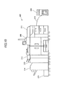
- Fig. 10 is a drawing illustrating an example of the configuration of an image forming system 400 according to the fourth embodiment.
- the image forming system 400 of the fourth embodiment is a production printing system in which an image forming apparatus 200 is provided with peripheral units having functions such as feeding, folding, stapling, cutting, etc., which may be combined at the time of use according to need.
- the image forming system 400 of the fourth embodiment includes a large volume paper feed unit 211, an inserter 212, a folding unit 213, a finisher 214 for stapling and punching, a cutter 215, and an information processing apparatus 300, which are connected to the image forming apparatus 200.
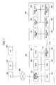
- Fig. 11 is a drawing illustrating an example of the hardware configuration of the image forming system 400 according to the fourth embodiment.
- the information processing apparatus 300 includes a network interface unit 301, a ROM 302, a RAM 303, a CPU 304, an HDD 305, and an interface unit 306, which are connected to each other through a bus B1.
- the information processing apparatus 300 is connected to the image forming apparatus 200 through a dedicated line 210.
- the CPU 300 of the information processing apparatus 300 is a computing unit that performs control operations, arithmetic operations, and data processing by executing programs stored in the ROM 302 and the RAM 303. Further, the CPU 304 performs overall control of the apparatus by executing programs, and also serves as a control unit of a paper feed unit 403 of the image forming apparatus 200.
- the HDD 305 is a nonvolatile storage device to store various programs and data.
- the stored programs and data include an OS (Operating System) and application programs providing various functions.
- the ROM 302 is a nonvolatile semiconductor memory (storage device) that can retain stored data even when the power is switched off.
- the RAM 303 is a volatile semiconductor memory (storage device) that temporarily stores programs and data.
- the network interface unit 301 is an interface with peripheral devices such as PCs 501 through 503 having a communication function that are connected through a network 500 such as a LAN or WAN, which is implemented by use of wired and/or wireless data transmission lines.
- the interface unit 306 is used to connect the information processing apparatus 300 to the image forming apparatus 200, and is connected to an interface unit 403 of the image forming apparatus 200 through the dedicated line 210.
- the image forming apparatus 200 connected to the information processing apparatus 300 through the dedicated line 210 includes a printing unit 401, a display unit 402, a paper feed unit 403, an interface unit 404, an operation unit 405, and a miscellaneous interface unit 406, which are connected to each other through a bus B2.
- the printing unit 401 includes a photosensitive unit, a fuser unit, etc., and forms an image on the surface of a paper sheet P based on image data.
- the display unit 402 and the operation unit 405 are formed of key switches (i.e., hard keys) and an LCD (liquid crystal display) that has a touch panel function (inclusive of software keys implemented by graphical user interface).
- the display unit 402 and the operation unit 405 are a display and input apparatus serving as a user interface that is used to exploit the functions of the image forming apparatus 200. Using the display unit 402 and the operation unit 405, a user may enter information indicative of the size or the like of the paper sheet P to be printed.
- the paper feed unit 403 is the paper feed apparatus 100 of the first embodiment, and feeds a paper sheet P stored in a paper feed cassette to the printing unit 401.
- the interface unit 404 is used for connection to the information processing apparatus 300, and is connected to the interface unit 306 of the information processing apparatus 300 through the dedicated line 210.
- the image forming system 400 having the configuration described above uses the CPU 304 of the information processing apparatus 300 to control the state of connection of relays situated between the electrodes of the paper feed belt 1 and the high-voltage power supply in the paper feed unit 403 of the image forming apparatus 200.
- This arrangement serves to feed a paper sheet P by use of optimal conditions for applying voltage.
- connection it is preferable to connect the image forming apparatus 200 to the information processing apparatus 300 through the dedicated line 210 since such a connection allows the paper feed unit 403 of the image forming apparatus 200 to be controlled at high speed. As long as the control of the paper feed unit 403 is performed at high speed, the connection may be provided by use of a network or the like.
- the paper feed unit 403 of the image forming apparatus 200 may be the paper feed apparatus 100 of the second or third embodiment. Regardless of the configuration used, a paper sheet P can be fed under proper electric power conditions without consuming needless electric power in response to the size, basis weight, and/or the like of the paper sheet P.
- the function of the CPU 304 of the information processing apparatus 300 to serve as a control unit to control the paper feed unit 403 of the image forming apparatus 200 may be provided in the image forming apparatus 200, or may be provided in the PC 501 or the like connected through a network or the like.
Landscapes
- Engineering & Computer Science (AREA)
- Mechanical Engineering (AREA)
- Physics & Mathematics (AREA)
- General Physics & Mathematics (AREA)
- Sheets, Magazines, And Separation Thereof (AREA)
- Feeding Of Articles By Means Other Than Belts Or Rollers (AREA)
Abstract
Description
- The disclosures herein relate to a print medium feeding apparatus, an image forming apparatus, and a print medium feeding system.
- An image forming apparatus such as a printer or a copier feeds paper sheets one by one to an image forming unit by separating a paper sheet from a stack of paper sheets stored in a sheet tray, and uses the image forming unit to print an image on the surface of the paper sheet, which is then discharged to outside the apparatus. If multiple paper sheets are fed at a time from the sheet tray, a paper jam may occur along the conveyance path or in the image forming unit, or a print failure may be caused. In order to improve the productivity of the image forming apparatus, there is a need to separate paper sheets one by one from a stack of paper sheets at high speed in a stable manner.
- An electrostatic adherence paper feed technology known in the art (see Japanese Patent Application Publication No.
2010-126317 - The electrostatic adherence paper feed technology may need to apply a large voltage to the electrodes to create sufficient paper sheet adherence when the paper sheet to be fed is larger than the paper feed belt. When the paper feed belt is the same size as the size of the largest sheet among paper sheets to be fed, voltage applied to the entirety of the paper feed belt at the time of feeding a small-sized paper sheet may result in needless consumption of electric power.
- Accordingly, it may be desirable to provide a print medium feeding apparatus that can feed a medium by the use of an appropriate amount of electric power responsive to the size of the medium.
- It is a general object of at least one embodiment of the present invention to provide a print medium feeding apparatus that substantially obviates one or more problems caused by the limitations and disadvantages of the related art.
- In one embodiment, a print medium feeding apparatus includes an endless belt disposed to face stacked media and configured to rotate, the endless belt divided into sections having electrodes, respectively, fixed terminals configured to be in contact with two or more of the electrodes while the two or more of the electrodes are passing through a position facing the media as the electrodes are moved by rotation of the endless belt, a voltage applying unit connected to the fixed terminals and configured to apply voltage to the two or more of the electrodes that are in contact with the fixed terminals, a connection unit configured to make and break a connection between the voltage applying unit and at least one of the fixed terminals, and a switching unit configured to change a state of the connection of the connection unit in response to size of the media.
- According to at least one embodiment, a print medium feeding apparatus is provided that can feed a medium by use of an appropriate amount of electric power responsive to the size of the medium.
- Other objects and further features of embodiments will be apparent from the following detailed description when read in conjunction with the accompanying drawings, in which:
-
Fig. 1 is a drawing illustrating an example of the appearance of an image forming apparatus that is provided with a paper feed apparatus according to a first embodiment; -
Fig. 2 is a drawing illustrating an example of the schematic configuration of a paper feed apparatus and a paper feed cassette according to the first embodiment; -
Fig. 3 is a drawing illustrating an example of the hardware configuration of the paper feed apparatus according to the first embodiment; -
Fig. 4 is a drawing illustrating an example of the configuration of the paper feed apparatus according to the first embodiment; -
Figs. 5A and 5B are drawings illustrating an example of the configuration of a paper feed belt of the paper feed apparatus according to the first embodiment; -
Fig. 6 is a drawing illustrating an example of another configuration of the paper feed apparatus according to the first embodiment; -
Fig. 7 is a drawing illustrating an example of the configuration of the paper feed apparatus according to a second embodiment; -
Fig. 8 is a drawing illustrating an example of sections to which voltage is applied in response to the size and basis weight of a paper sheet in the paper feed apparatus according to the second embodiment; -
Fig. 9 is a drawing illustrating an example of the configuration of a paper feed belt of the paper feed apparatus according to a third embodiment; -
Fig. 10 is a drawing illustrating an example of the appearance of an image forming system according to a -
Fig. 11 is a drawing illustrating an example of the hardware configuration of the image forming system according to the fourth embodiment. - In the following, embodiments will be described by referring to the accompanying drawings. In these drawings, the same elements are referred to by the same references, and repetitive description thereof may be omitted.
-
Fig. 1 is a drawing illustrating an example of the appearance of animage forming apparatus 200 that is provided with a paper feed apparatus according to a first embodiment. - As illustrated in
Fig. 1 , theimage forming apparatus 200 includes an image forming apparatusmain section 201, an automatic document feeder (ADF) 202, afinisher 203 having a stapler and a shift tray, a duplex-printing buffer/flipper unit 204, an extendedpaper feed tray 205, a one-bin discharge tray 207, aninsert feeder 208, and so on. - The image forming apparatus
main section 201 includes a scanner unit, an image forming unit, a developer unit, a fuser unit, and a paper feed apparatus, etc., accommodated therein, and prints an image on the surface of a paper sheet fed from the paper feed apparatus. - The image forming apparatus
main section 201 may use an electrophotographic process to print an image on the surface of a paper sheet. The process of forming an image may be a different process such as an inkjet process. Further, it does not matter whether the process is a monochrome process or a full color process. -
Fig. 2 is a drawing illustrating an example of the schematic configuration of apaper feed apparatus 100 and a paper feed cassette 9 according to the first embodiment. - As illustrated in
Fig. 2 , thepaper feed apparatus 100 includes apaper feed belt 1, adrive roller 141, a drivenroller 142, and a high-voltage power supply 121. - The
paper feed belt 1 is an endless belt having a plurality of electrodes embedded therein that are covered with an insulating layer. Thepaper feed belt 1 is looped around thedrive roller 141 and the drivenroller 142. - The
drive roller 141 is rotated by a drive unit (not shown) to rotate thepaper feed belt 1. The drivenroller 142 is rotated by thepaper feed belt 1 that is rotated by thedrive roller 141. - The high-
voltage power supply 121 applies voltage to the electrodes in thepaper feed belt 1 to polarize the surface of a paper sheet P coming in contact with thepaper feed belt 1, thereby causing the paper sheet P to adhere to thepaper feed belt 1. - The paper feed cassette 9 storing paper sheets P includes a sheet-width regulating guide 4, a sheet-rear-
end regulating plate 5, a bottom plate 6, a fan 7, anoptical sensor 8, aconveyor sensor 10, and aconveyor roller 11. - The sheet-width regulating guide 4 and the sheet-rear-
end regulating plate 5 secure the paper sheets P in their place and also detect the size of the paper sheets P upon the paper sheets P being set. - The bottom plate 6 elevates to such a height that the top of the stored paper sheets P can be detected by the
optical sensor 8, thereby raising the paper sheets P to the position at which paper feeding can be performed by thepaper feed apparatus 100. - The fan 7 blows air into a space over the stacked paper sheets P to flip a sheet, thereby causing the topmost paper sheet P to come in contact with the
paper feed belt 1. The paper sheet P may come in contact with thepaper feed belt 1 while voltage is applied to the embedded electrodes. When this happens, the surface of the paper sheet P polarizes, and thus adheres to thepaper feed belt 1. Rotation of thepaper feed belt 1 then causes the paper sheet P to be conveyed to outside the paper feed cassette 9. - The
conveyor sensor 10 detects the paper sheet P that is fed by thepaper feed belt 1 to a conveyor path. Upon theconveyor sensor 10 detecting the paper sheet P, thepaper feed apparatus 100 deactivates the high-voltage power supply 121 to stop the adherence and conveyance of the paper sheet P. - The
conveyor roller 11 conveys the paper sheet P to the image forming unit or the like situated at the next stage as the paper sheet P is fed from the paper feed cassette 9 by thepaper feed belt 1 of thepaper feed apparatus 100. -
Fig. 3 is a drawing illustrating an example of the hardware configuration of thepaper feed apparatus 100 according to the first embodiment. - As illustrated in
Fig. 3 , thepaper feed apparatus 100 includes, in addition to thepaper feed belt 1, the high-voltage power supply 121, and so on, a CPU (Central Processing Unit) 171, an HDD (Hard Disk Drive) 172, a ROM (Read Only Memory) 173, a RAM (Random Access Memory) 174, anetwork interface unit 175, a recordingmedium interface unit 176, etc., which are connected to each other through a bus B. - The
CPU 171 is a computing unit that performs control operations, arithmetic operations, and data processing by executing programs stored in theROM 173 and theRAM 174. TheCPU 171 performs overall control of the apparatus by executing programs, and also serves as a switchover unit to select the electrodes of thepaper feed belt 1 to which the high-voltage power supply 121 applies voltage. - The
HDD 172 is a nonvolatile storage device to store various programs and data. The stored programs and data include an OS (Operating System) and application programs providing various functions. - The
ROM 173 is a nonvolatile semiconductor memory (storage device) that can retain stored data even when the power is switched off. TheRAM 174 is a volatile semiconductor memory (storage device) that temporarily stores programs and data. - The
network interface unit 175 is an interface with peripheral devices having a communication function that are connected through a network such as a LAN (Local Area Network) or WAN (Wide Area Network), which is implemented by use of wired and/or wireless data transmission lines. - The recording
medium interface unit 176 is an interface with a computer-readable recording medium 177 such as a CD-ROM, a flexible disk (FD), a CD-R, a DVD (Digital Versatile Disk), or the like, which is connected through a data transmission line such as a USB (Universal Serial Bus). - A predetermined program is stored in the
recording medium 177. The program stored in therecording medium 177 is installed in thepaper feed apparatus 100 via the recordingmedium interface unit 176. The installed program is ready to be executed by theCPU 171. - The
CPU 171, theHDD 172, theROM 173, theRAM 174 and the like may be shared with one or more other units such as the image forming apparatusmain section 201. -
Fig. 4 is a drawing illustrating an example of the configuration of thepaper feed apparatus 100 according to the first embodiment. - As illustrated in
Fig. 4 , thepaper feed apparatus 100 includes, in addition to thepaper feed belt 1, thedrive roller 141 and the drivenroller 142, the high-voltage power supply 121, acontrol unit 122, etc. Thepaper feed apparatus 100 feeds a paper sheet taken from the paper feed cassette 9. - The
paper feed belt 1 is looped around thedrive roller 141 and the drivenroller 142. Thepaper feed belt 1 is rotated in a clockwise direction by thedrive roller 141 that rotates in the direction indicated by an arrow. The distance between thedrive roller 141 and the drivenroller 142 is equivalent to the longitudinal length of an A3 paper sheet. The distance between thedrive roller 141 and the drivenroller 142 may be adaptively set in response to the size of the paper sheet P that is to be fed. - Further, the
paper feed belt 1 has four sections A through D arranged in the rotational direction thereof. The four sections A through D have fourelectrodes 101 through 104, respectively, embedded therein. -
Figs. 5A and 5B are drawings illustrating an example of the configuration of thepaper feed belt 1 of thepaper feed apparatus 100 according to the first embodiment.Fig. 5A is a plan view of the section A and part of the section B of thepaper feed belt 1 viewed from the inner side of thepaper feed belt 1.Fig. 5B is a schematic view of the cross-section taken along the line a-a' illustrated inFig. 5A . - As illustrated in
Fig. 5A , sections A and B of thepaper feed belt 1 have a pair of comb-shapedelectrodes electrodes paper feed belt 1 into the spaces between the teeth of the other electrode. The same also applies in the case of the remaining sections C and D. - It may be noted that the
electrode 101 refers to the pair ofelectrodes electrodes 102 through 104. As illustrated inFig. 5A and Fig. 5B , theelectrode 101 is covered with an insulatinglayer 190, except for areas corresponding toopenings layer 190 that are situated near the side ends of thepaper feed belt 1. The same also applies in the case of the remainingelectrodes 102 through 104. The side ends ofelectrode 101 near the side ends of thepaper feed belt 1 are exposed through theopenings paper feed belt 1. The same also applies in the case of the remainingelectrodes 102 through 104. The side ends of each of theelectrodes 101 through 104 exposed through the openings receive a voltage applied thereto. In the section in which voltage is applied to the electrode, the surface of thepaper feed belt 1 is made to exert an adhering force to attract a paper sheet P. Because theelectrodes 101 through 104 are covered with the insulating layer, no electric charge moves between the electrodes. Voltage control may be performed such that different voltages are applied to theelectrodes 101 through 104. - On the inner side of the
paper feed belt 1, as illustrated inFig. 4 , roller-shaped, rotatable fixedterminals 131 through 134 are disposed that are in contact with the side ends of theelectrodes 101 through 104 exposed through the openings. The fixedterminal 131 disposed at the position facing the paper feed cassette 9 (not shown) is directly connected to the high-voltage power supply 121. The fixedterminal 132 is connected through arelay 151 to the high-voltage power supply 121. The fixedterminals terminals terminals 131 are arranged at such intervals that one electrode arranged in one section of thepaper feed belt 1 does not come in contact with two fixed terminals simultaneously. - The
relay 151 is a connecting unit situated between the high-voltage power supply 121 and the fixedterminal 132. Therelay 151 is controlled by thecontrol unit 122 that serves as a switchover unit for changing the state of connection of therelay 151, thereby connecting the fixedterminal 132 either to the high-voltage power supply 121 or to ground. - The high-
voltage power supply 121 applies voltage to those electrodes among theelectrodes 101 through 104 that are in contact with either the fixedterminal 131 or the fixedterminal 132 at the time of feeding a paper sheet P, thereby polarizing the surface of the paper sheet P coming in contact with the area of thepaper feed belt 1 to which the voltage is applied, and thus causing the paper sheet P to adhere to thepaper feed belt 1. One of the two comb-shaped electrodes included in each of theelectrodes 101 through 104 may receive a positive polarity voltage, and the other may receive a negative polarity voltage. Alternatively, one of the two comb-shaped electrodes may be connected to ground. - The
control unit 122 serves as a switchover unit for changing the state of connection of therelay 151 based on information indicative of the size of the paper sheet P, thereby connecting the fixedterminal 132 either to the high-voltage power supply 121 or to ground. Thecontrol unit 122 obtains the information indicative of the size of the paper sheet P from information entered by a user or from the results of detections made by the sheet-width regulating guide 4 and the sheet-rear-end regulating plate 5 of the paper feed cassette 9. - A description will be given of operations performed by the
paper feed apparatus 100 of the first embodiment when feeding a paper sheet P from the paper feed cassette 9. The paper sheets P are stored in the paper feed cassette 9, such that they are placed against the inner wall thereof positioned on the same side as the section D. - At the time of feeding a paper sheet P, the
control unit 122 obtains information indicative of the size of the paper sheet P from information entered by a user or from the results of detections made by the sheet-width regulating guide 4 and the sheet-rear-end regulating plate 5 of the paper feed cassette 9. - The paper sheet P stored in the paper feed cassette 9 may be A3 portrait. In this case, the
control unit 122 controls the state of connection of therelay 151 to connect the fixedterminal 132 to the high-voltage power supply 121. In this state, the high-voltage power supply 121 supplies voltage. When thepaper feed belt 1 is in such a position as illustrated inFig. 4 , the voltage is applied to theelectrode 104 of the section D being in contact with the fixedterminal 131 and to theelectrode 103 of the section C being in contact with the fixedterminal 132. As thepaper feed belt 1 rotates, different electrodes successively come in contact with the fixedterminals paper feed belt 1 that face the paper feed cassette 9 always have the electrodes thereof receiving the voltage, thereby exerting an adhering force to attract the paper sheet P. - The paper sheet P stored in the paper feed cassette 9 may be A4 landscape. In this case, the
control unit 132 controls the state of connection of therelay 151 to connect the fixedterminal 132 to ground. In this state, the high-voltage power supply 121 supplies voltage. When thepaper feed belt 1 is in such a position as illustrated inFig. 4 , voltage is applied only to theelectrode 104 of the section D being in contact with the fixedterminal 131. As thepaper feed belt 1 rotates, different electrodes successively come in contact with the fixedterminal 131. Despite this, the section of thepaper feed belt 1 that faces the paper feed cassette 9 always has the electrode thereof receiving the voltage, thereby exerting an adhering force to attract the paper sheet P. - In this manner, control is performed based on the information indicative of the size of a paper sheet P, such that the fixed
terminal 132 is connected to the high-voltage power supply 121 when feeding a large-size paper sheet P, and is not connected to the high-voltage power supply 121 when feeding a small-size paper sheet P. Through such control, the large-size paper sheet can be reliably fed, and, also, needless consumption of electric power is avoided by applying voltage to the electrode(s) of the fewest necessary section(s) when feeding the small-size paper sheet P. - Further, as illustrated in
Fig. 6 , a remaining charge removingpower supply 123 may be provided and connected to the fixedterminals power supply 123 applies the voltage for removing remaining charge to an electrode that comes in contact with the fixedterminals voltage power supply 121 while being in contact with the fixedterminal 131 and disconnects from the fixedterminal 131 as thepaper feed belt 1 rotates. An effective method to remove remaining charge is to apply an alternating voltage to the electrode while making the amplitude of the alternating voltage smaller and smaller. The remaining charge removingpower supply 123 may thus be preferably an alternating current power supply and a pulse-voltage power supply capable of applying voltages of opposite polarities, and may preferably apply the voltage to the electrode until the amplitude of the voltage reaches 0 V. - The fixed
terminals power supply 123 or to ground throughrelays 151 through 154 whose connection states are controlled by thecontrol unit 122. - In the
paper feed apparatus 100, charge may remain in an electrode to which the high-voltage power supply 121 applies high voltage in order to feed a heavy basis weight paper sheet P, for example. In such a case, thecontrol unit 122 connects the remaining charge removingpower supply 123 to the fixed terminal to which the high-voltage power supply 121 does not supply voltage, so that an alternating voltage as described above is applied to each electrode to remove remaining charge. - Voltage applied by the high-
voltage power supply 121 to an electrode may be small when feeding a light basis weight paper sheet P. In this case, remaining charge may not be in existence. Thecontrol unit 122 thus controls the connection state of therelays 151 through 154 such that the fixed terminals not connected to the high-voltage power supply 121 are connected to ground. - As described above, the remaining charge removing
power supply 123 is provided to remove charge remaining in each electrode. This arrangement prevents thepaper feed belt 1 from exerting a needless adhering force, thereby ensuring a reliable feeding operation of thepaper feed apparatus 100. - As described heretofore, the
paper feed apparatus 100 of the first embodiment uses thecontrol unit 122, which changes the state of connection of therelay 151 in response to information indicative of the size of a paper sheet P to change the sections to which the high-voltage power supply 121 applies voltage, thereby attracting and feeding the paper sheet P by use of proper electric power responsive to the size of the paper sheet P. Compared to the case in which the paper sheet P is conveyed by applying voltage to all the electrodes embedded in thepaper feed belt 1, for example, power consumption is reduced to a half when conveying an A3 portrait paper sheet P, and power consumption is reduced to a quarter when conveying an A4 landscape paper sheet P. Further, the high-voltage power supply 121 may be powered off while feeding is not performed during an interval between paper sheets, which achieves further reduction in power consumption. Moreover, the provision of the remaining charge removingpower supply 123 makes it possible to feed a paper sheet P in a more reliable manner. - The description of the first embodiment has been given with respect to an example in which the
paper feed belt 1 is divided into the four sections A through D in a rotational direction. This is not a limiting example, and the number of divided sections may be two or more. The number of sections may be increased to properly cope with an increased variety of paper sheet sizes, and voltage is applied in response to the size of a paper sheet P to feed the paper sheet P by use of proper electric power while reducing needless power consumption. - In the following, a second embodiment will be described with reference to the accompanying drawings. A description will be omitted of the same elements as those of the embodiment already described.
- The
paper feed apparatus 100 of the second embodiment differs from that of the first embodiment in that thepaper feed belt 1 is divided into sections in a direction perpendicular to the rotational direction. -
Fig. 7 is a drawing illustrating an example of the configuration of thepaper feed apparatus 100 according to the second embodiment. - As illustrated in
Fig. 7 , thepaper feed belt 1 is divided into sections A through C in a direction perpendicular to the rotational direction. The sections A through C have a pair of comb-shapedelectrodes electrodes electrodes paper feed belt 1 into the spaces between the teeth of the other electrode of the given pair.Electrodes electrode 101. This also applies to other electrodes. - The
paper feed belt 1 has a width (i.e., the span in the direction perpendicular to the rotational direction) equal to the longitudinal length of an A3 size paper sheet. The divided sections A through C are provided such that their widths satisfy the following relationships: a ratio of the width of the section A to the width of the section B = 1:(20.5 - 1), and a ratio of the combined width of the sections A and B to the width of the section C = 1:(20.5 - 1). The widths and numbers of divided sections may be set differently as appropriate. - The
electrodes layer 190. The side ends of theelectrodes openings - Fixed terminals that come in contact with the side ends of the
electrodes paper feed belt 1. These fixed terminals are connected either to high-voltage power supply relays control unit 122. - The high-
voltage power supply 121a is connected to theelectrodes voltage power supply 121b is connected to theelectrodes voltage power supplies - The
control unit 122 changes the state of connection of therelays voltage power supplies paper feed apparatus 100. - The paper sheets P are stored in the paper feed cassette 9 facing the
paper feed belt 1, such that they are placed against the top right corner of the paper feed cassette 9 (wherein the term "top right" is defined with respect to the positional arrangements illustrated inFig. 7 ). A description will be given of an operation of feeding a paper sheet P in thepaper feed apparatus 100. - At the time of feeding a paper sheet P, the
control unit 122 obtains information indicative of the size of the paper sheet P from information entered by a user or from the results of detections made by the sheet-width regulating guide 4 and the sheet-rear-end regulating plate 5 of the paper feed cassette 9. - The paper sheet P stored in the paper feed cassette 9 may be A5 portrait. In this case, the
control unit 122 controls therelays electrode 105 of the section B and theelectrode 106 of the section C to ground. The high-voltage power supply 121 applies voltage only to theelectrode 101 of the section A of thepaper feed belt 1, so that thepaper feed belt 1 attracts and conveys the A5 portrait sheet P by use of only the section A. - When an A4 portrait paper sheet P is to be conveyed, the
control unit 122 controls therelays electrode 105 of the section B to the high-voltage power supply 121, and controls therelays electrode 106 of the section C to ground. The high-voltage power supply 121 applies voltage to theelectrode 101 of the section A and to theelectrode 105 of the section B, so that thepaper feed belt 1 attracts and conveys the A4 portrait sheet P by use of the section A and the section B. - When an A3 portrait paper sheet P is to be conveyed, the
control unit 122 controls the state of connection of the relays to connect theelectrode 105 of the section B and theelectrode 106 of the section C to the high-voltage power supply 121. In this case, thepaper feed belt 1 attracts and conveys the A3 portrait sheet P by use of all the sections A, B and C. - Moreover, the
control unit 122 may change the sections to which to apply voltage in response to the size and basis weight of a paper sheet P to be fed, based on information indicative of a sheet type entered by a user. -
Fig. 8 is a drawing illustrating an example of sections to which voltage is applied in response to the size and basis weight of a paper sheet in thepaper feed apparatus 100 according to the second embodiment. - As illustrated in
Fig. 8 , in the case of the A5-size paper sheet P, thecontrol unit 122 controls the states of connection of therelays control unit 122 controls the states of connection of therelays - In the case of a B5-size paper sheet P being conveyed, the
control unit 122 controls the states of connection of therelays control unit 122 controls the states of connection of therelays - In this manner, the sections to which voltage is applied are changed in response to the size and basis weight of paper sheets P, so that the paper sheets P are properly conveyed and fed with proper power consumption even when the paper sheets P having the same size have different weights due to difference in paper type.
- As described heretofore, the
paper feed apparatus 100 of the second embodiment uses thecontrol unit 122, which changes the states of connection of therelays paper feed belt 1, thereby to change the sections to which the high-voltage power supply 121 applies voltage. Accordingly, the paper sheet P is attracted and fed by using a proper amount of electric power for the size and basis weight of the paper sheet P. Compared to the case in which the paper sheet P is conveyed by applying voltage to all the electrodes embedded in thepaper feed belt 1, for example, power consumption is reduced to three tenths when feeding an A5 portrait paper sheet P, and power consumption is reduced to a half when feeding an A3 portrait paper sheet P. Further, the high-voltage power supply 121 may be powered off while feeding is not performed during an interval between paper sheets, which achieves further reduction in power consumption. - The description of the second embodiment has been given with respect to an example in which the
paper feed belt 1 is divided into the three sections A through C in the direction perpendicular to the rotational direction. This is not a limiting example, and the number of divided sections may be two or more. The number of sections may be increased to properly cope with an increased variety of paper sheet sizes and types, and voltage is applied in response to the size of a paper sheet P to feed the paper sheet P by use of proper electric power. - In the following, a third embodiment will be described with reference to the accompanying drawings. A description will be omitted of the same elements as those of the embodiments already described.
- The
paper feed apparatus 100 of the third embodiment differs from that of the first embodiment and the second embodiment in that thepaper feed belt 1 is divided into sections in the rotational direction as well as in the direction perpendicular to the rotational direction. - The
paper feed belt 1 of the third embodiment is divided into four areas in the rotational direction and further divided into three sections in the direction perpendicular to the rotational direction. In total, twelve sections A1, B1, C1, ..., A4, B4, and C4 are created. -
Fig. 9 is a drawing illustrating an example of the configuration of thepaper feed belt 1 used by thepaper feed apparatus 100 of the third embodiment.Fig. 9 is a plan view of thepaper feed belt 1 as viewed from the inner side of the loop to show the areas A1, B1, C1, A2, B2, and C2 of thepaper feed belt 1. - As illustrated in
Fig. 9 , thepaper feed belt 1 has in each of the divided sections a pair of comb-shaped electrodes, which are arranged such that the teeth of one electrode extend in the direction perpendicular to the rotational direction into the spaces between the teeth of the other electrode. - The electrodes provided in the respective sections are partially covered with the insulating
layer 190, and are exposed toward the inner side of thepaper feed belt 1 through openings that are formed at side ends of the electrodes opposite to each other in the direction perpendicular to the rotational direction. - Fixed terminals are disposed on the inner side of the
paper feed belt 1 to come in contact with the side ends of the electrodes at the position facing the paper sheets P stored in the paper feed cassette 9. Each of the fixed terminals is connected either to the high-voltage power supply or to ground through relays whose state of connection is changed by the control unit. - The control unit changes the state of connection of the relays situated between the high-voltage power supply and the fixed terminals in response to the size of or the size and basis weight of the paper sheet P to be fed by the
paper feed apparatus 100, thereby changing the electrodes to which the high-voltage power supply applies voltage at the time of feeding the paper sheet P. - In this manner, electrodes are provided in the sections into which the
paper feed belt 1 is divided in the rotational direction as well as in the direction perpendicular to the rotational direction, and the electrodes to which voltage is applied are selected in response to the size, basis weight, and/or the like of the paper sheet P. This arrangement can feed paper sheets P of various sizes and types by use of proper electric power while reducing needless power consumption. - In the following, a fourth embodiment will be described with reference to the accompanying drawings. A description will be omitted of the same elements as those of the embodiments already described.
-
Fig. 10 is a drawing illustrating an example of the configuration of animage forming system 400 according to the fourth embodiment. - The
image forming system 400 of the fourth embodiment is a production printing system in which animage forming apparatus 200 is provided with peripheral units having functions such as feeding, folding, stapling, cutting, etc., which may be combined at the time of use according to need. Theimage forming system 400 of the fourth embodiment includes a large volumepaper feed unit 211, aninserter 212, afolding unit 213, afinisher 214 for stapling and punching, acutter 215, and aninformation processing apparatus 300, which are connected to theimage forming apparatus 200. -
Fig. 11 is a drawing illustrating an example of the hardware configuration of theimage forming system 400 according to the fourth embodiment. - The
information processing apparatus 300 includes anetwork interface unit 301, aROM 302, aRAM 303, aCPU 304, anHDD 305, and aninterface unit 306, which are connected to each other through a bus B1. Theinformation processing apparatus 300 is connected to theimage forming apparatus 200 through adedicated line 210. - The
CPU 300 of theinformation processing apparatus 300 is a computing unit that performs control operations, arithmetic operations, and data processing by executing programs stored in theROM 302 and theRAM 303. Further, theCPU 304 performs overall control of the apparatus by executing programs, and also serves as a control unit of apaper feed unit 403 of theimage forming apparatus 200. - The
HDD 305 is a nonvolatile storage device to store various programs and data. The stored programs and data include an OS (Operating System) and application programs providing various functions. - The
ROM 302 is a nonvolatile semiconductor memory (storage device) that can retain stored data even when the power is switched off. TheRAM 303 is a volatile semiconductor memory (storage device) that temporarily stores programs and data. - The
network interface unit 301 is an interface with peripheral devices such asPCs 501 through 503 having a communication function that are connected through anetwork 500 such as a LAN or WAN, which is implemented by use of wired and/or wireless data transmission lines. - The
interface unit 306 is used to connect theinformation processing apparatus 300 to theimage forming apparatus 200, and is connected to aninterface unit 403 of theimage forming apparatus 200 through thededicated line 210. - The
image forming apparatus 200 connected to theinformation processing apparatus 300 through thededicated line 210 includes aprinting unit 401, adisplay unit 402, apaper feed unit 403, aninterface unit 404, anoperation unit 405, and amiscellaneous interface unit 406, which are connected to each other through a bus B2. - The
printing unit 401 includes a photosensitive unit, a fuser unit, etc., and forms an image on the surface of a paper sheet P based on image data. - The
display unit 402 and theoperation unit 405 are formed of key switches (i.e., hard keys) and an LCD (liquid crystal display) that has a touch panel function (inclusive of software keys implemented by graphical user interface). Thedisplay unit 402 and theoperation unit 405 are a display and input apparatus serving as a user interface that is used to exploit the functions of theimage forming apparatus 200. Using thedisplay unit 402 and theoperation unit 405, a user may enter information indicative of the size or the like of the paper sheet P to be printed. - The
paper feed unit 403 is thepaper feed apparatus 100 of the first embodiment, and feeds a paper sheet P stored in a paper feed cassette to theprinting unit 401. - The
interface unit 404 is used for connection to theinformation processing apparatus 300, and is connected to theinterface unit 306 of theinformation processing apparatus 300 through thededicated line 210. - The
image forming system 400 having the configuration described above uses theCPU 304 of theinformation processing apparatus 300 to control the state of connection of relays situated between the electrodes of thepaper feed belt 1 and the high-voltage power supply in thepaper feed unit 403 of theimage forming apparatus 200. This arrangement serves to feed a paper sheet P by use of optimal conditions for applying voltage. - It is preferable to connect the
image forming apparatus 200 to theinformation processing apparatus 300 through thededicated line 210 since such a connection allows thepaper feed unit 403 of theimage forming apparatus 200 to be controlled at high speed. As long as the control of thepaper feed unit 403 is performed at high speed, the connection may be provided by use of a network or the like. - The
paper feed unit 403 of theimage forming apparatus 200 may be thepaper feed apparatus 100 of the second or third embodiment. Regardless of the configuration used, a paper sheet P can be fed under proper electric power conditions without consuming needless electric power in response to the size, basis weight, and/or the like of the paper sheet P. - The function of the
CPU 304 of theinformation processing apparatus 300 to serve as a control unit to control thepaper feed unit 403 of theimage forming apparatus 200 may be provided in theimage forming apparatus 200, or may be provided in thePC 501 or the like connected through a network or the like. - Although the present invention has been described heretofore by referring to one or more embodiments, the present invention is not limited to such embodiments. Various variations and modifications may be made without departing from the scope of the present invention.
Claims (10)
- A print medium feeding apparatus, comprising:an endless belt disposed to face stacked media and configured to rotate, the endless belt divided into sections having electrodes, respectively;fixed terminals configured to be in contact with two or more of the electrodes while the two or more of the electrodes are passing through a position facing the media as the electrodes are moved by rotation of the endless belt;a voltage applying unit connected to the fixed terminals and configured to apply voltage to the two or more of the electrodes that are in contact with the fixed terminals;a connection unit configured to make and break a connection between the voltage applying unit and at least one of the fixed terminals; anda switching unit configured to change a state of the connection of the connection unit in response to size of the media.
- The print medium feeding apparatus as claimed in claim 1, wherein the sections of the endless belt are formed by dividing the endless belt in a rotational direction thereof.
- The print medium feeding apparatus as claimed in claim 1 or 2, wherein the sections of the endless belt are formed by dividing the endless belt in a direction perpendicular to a rotational direction thereof.
- The print medium feeding apparatus as claimed in any one of claims 1 to 3, wherein the switching unit is configured to change the state of the connection of the connection unit in response to basis weight of the media.
- The print medium feeding apparatus as claimed in any one of claims 1 to 4, further comprising a remaining charge removing unit configured to apply alternating voltage to the electrodes to which the voltage applying unit has applied the voltage.
- The print medium feeding apparatus as claimed in any one of claims 1 to 5, further comprising a ground unit configured to connect, to a ground, one or more electrodes among the electrodes of the endless belt, which one or more electrodes are not receiving the voltage applied by the voltage applying unit.
- The print medium feeding apparatus as claimed in any one of claims 1 to 6, wherein each of the electrodes is a pair of comb-shaped electrodes, which are arranged such that teeth of one of the comb-shaped electrodes extend in a direction perpendicular to a rotational direction of the endless belt into spaces between teeth of another of the comb-shaped electrodes.
- An image forming apparatus, comprising the print medium feeding apparatus claimed in any one of claims 1 to 7.
- A system, comprising:a print medium feeding apparatus configured to feed a medium; andan information processing apparatus,wherein the print medium feeding apparatus includes:an endless belt disposed to face stacked media and configured to rotate, the endless belt divided into sections having electrodes, respectively;fixed terminals configured to be in contact with two or more of the electrodes while the two or more of the electrodes are passing through a position facing the media as the electrodes are moved by rotation of the endless belt;a voltage applying unit connected to the fixed terminals and configured to apply voltage to the two or more of the electrodes that are in contact with the fixed terminals; anda connection unit configured to make and break a connection between the voltage applying unit and at least one of the fixed terminals,wherein the information processing apparatus includes a switching unit configured to change a state of the connection of the connection unit in response to size of the media.
- A method of feeding a medium, comprising:rotating an endless belt disposed to face stacked media, the endless belt divided into sections having electrodes, respectively;applying voltage to one or more of the electrodes while the one or more of the electrodes are passing through a position facing the media as the electrodes are moved by rotation of the endless belt,wherein a number of the electrodes to which the voltage is applied is changed in response to size of the media.
Applications Claiming Priority (1)
| Application Number | Priority Date | Filing Date | Title |
|---|---|---|---|
| JP2012052869A JP2013184807A (en) | 2012-03-09 | 2012-03-09 | Medium feeding device, image forming apparatus and medium feeding system |
Publications (2)
| Publication Number | Publication Date |
|---|---|
| EP2637065A2 true EP2637065A2 (en) | 2013-09-11 |
| EP2637065A3 EP2637065A3 (en) | 2017-11-01 |
Family
ID=47912943
Family Applications (1)
| Application Number | Title | Priority Date | Filing Date |
|---|---|---|---|
| EP13157722.3A Withdrawn EP2637065A3 (en) | 2012-03-09 | 2013-03-05 | Print medium feeding apparatus with electrode in endless belt |
Country Status (3)
| Country | Link |
|---|---|
| US (1) | US20130234385A1 (en) |
| EP (1) | EP2637065A3 (en) |
| JP (1) | JP2013184807A (en) |
Cited By (1)
| Publication number | Priority date | Publication date | Assignee | Title |
|---|---|---|---|---|
| WO2016111252A1 (en) * | 2015-01-08 | 2016-07-14 | Canon Kabushiki Kaisha | Sheet feeding apparatus and image forming apparatus |
Families Citing this family (3)
| Publication number | Priority date | Publication date | Assignee | Title |
|---|---|---|---|---|
| JP6048016B2 (en) * | 2012-09-07 | 2016-12-21 | 株式会社リコー | Sheet separating and conveying apparatus and image forming apparatus |
| JP6274566B2 (en) * | 2014-02-26 | 2018-02-07 | 株式会社リコー | Sheet conveying apparatus and image forming apparatus |
| US10459388B2 (en) * | 2015-11-19 | 2019-10-29 | Canon Kabushiki Kaisha | Image forming apparatus and recording material determination apparatus |
Citations (1)
| Publication number | Priority date | Publication date | Assignee | Title |
|---|---|---|---|---|
| JP2010126317A (en) | 2008-11-28 | 2010-06-10 | Tsukuba Seiko Co Ltd | Delivery device for stacked object, and delivery method for stacked object |
Family Cites Families (11)
| Publication number | Priority date | Publication date | Assignee | Title |
|---|---|---|---|---|
| JPS60137733A (en) * | 1983-12-26 | 1985-07-22 | Fuji Xerox Co Ltd | Device for sending sheet out |
| JP3159727B2 (en) * | 1990-10-11 | 2001-04-23 | 株式会社リコー | Paper feeder |
| EP0636486B1 (en) * | 1993-07-28 | 2001-11-28 | Canon Kabushiki Kaisha | An ink jet recording apparatus and a process of ink jet recording |
| DE19643106A1 (en) * | 1995-10-28 | 1997-04-30 | Heidelberger Druckmasch Ag | Device for conveying sheets in a printing machine |
| JP3937786B2 (en) * | 2001-10-02 | 2007-06-27 | キヤノン株式会社 | Sheet conveying apparatus and image forming apparatus provided with the same |
| JP2010024051A (en) * | 2008-06-19 | 2010-02-04 | Canon Inc | Recording medium transport device |
| JP2010037047A (en) * | 2008-08-05 | 2010-02-18 | Ricoh Co Ltd | Sheet material feeder and image forming device using the same |
| JP5223600B2 (en) * | 2008-10-31 | 2013-06-26 | 株式会社リコー | Paper feeding device and image forming apparatus |
| JP5429621B2 (en) * | 2009-09-03 | 2014-02-26 | 株式会社リコー | Sheet material feeding apparatus and image forming apparatus provided with the same |
| JP5545543B2 (en) * | 2010-09-09 | 2014-07-09 | 株式会社リコー | Sheet conveying apparatus and image forming apparatus |
| JP5984048B2 (en) * | 2012-06-28 | 2016-09-06 | 株式会社リコー | Sheet conveying apparatus and image forming apparatus |
-
2012
- 2012-03-09 JP JP2012052869A patent/JP2013184807A/en active Pending
-
2013
- 2013-03-01 US US13/781,953 patent/US20130234385A1/en not_active Abandoned
- 2013-03-05 EP EP13157722.3A patent/EP2637065A3/en not_active Withdrawn
Patent Citations (1)
| Publication number | Priority date | Publication date | Assignee | Title |
|---|---|---|---|---|
| JP2010126317A (en) | 2008-11-28 | 2010-06-10 | Tsukuba Seiko Co Ltd | Delivery device for stacked object, and delivery method for stacked object |
Cited By (1)
| Publication number | Priority date | Publication date | Assignee | Title |
|---|---|---|---|---|
| WO2016111252A1 (en) * | 2015-01-08 | 2016-07-14 | Canon Kabushiki Kaisha | Sheet feeding apparatus and image forming apparatus |
Also Published As
| Publication number | Publication date |
|---|---|
| JP2013184807A (en) | 2013-09-19 |
| US20130234385A1 (en) | 2013-09-12 |
| EP2637065A3 (en) | 2017-11-01 |
Similar Documents
| Publication | Publication Date | Title |
|---|---|---|
| US8403325B2 (en) | Image forming apparatus including sheet stacking apparatus | |
| EP3403956B1 (en) | Paper feeding device, image forming apparatus and paper feeding method | |
| CN101169610A (en) | Image forming device, image forming method, and transfer device | |
| US20130234385A1 (en) | Print medium feeding apparatus with electrode in endless belt | |
| US8864134B2 (en) | Image forming apparatus, method of controlling image forming apparatus, and storage medium | |
| JP2010105807A (en) | Paper feeding device and image forming device | |
| US6480697B2 (en) | Image-forming apparatus, network-type image-forming apparatus, and method therefor | |
| JP5928276B2 (en) | Image forming apparatus | |
| JPH1160024A (en) | Sheet medium storage mechanism and image forming apparatus | |
| CN105253652B (en) | Stack device and imaging device | |
| JP7594465B2 (en) | Paper feed mechanism | |
| US7766315B2 (en) | Sheet stacking apparatus and method of controlling the sheet stacking apparatus | |
| JPH08179576A (en) | Cut paper printing device | |
| JP6044187B2 (en) | Sheet separating and conveying apparatus and image forming apparatus | |
| JP2021092743A (en) | Image forming apparatus and medium conveyance control method | |
| JP7385811B2 (en) | image forming device | |
| JP2684724B2 (en) | Recording device | |
| JP7419759B2 (en) | Sheet conveyance device and image forming device | |
| CN208070884U (en) | Paper feed and image forming apparatus | |
| JP2010159124A (en) | Sheet ejecting device, sheet processing device and image forming device | |
| JP5991017B2 (en) | Paper conveying apparatus and image forming apparatus | |
| JP2001225980A (en) | Paper feeder | |
| JP2004035175A (en) | Sheet handling device and image formation device equipped with sheet handling device | |
| JP2020132341A (en) | Sheet ejection device and image forming device | |
| JP5267081B2 (en) | Paper discharge device and image forming apparatus |
Legal Events
| Date | Code | Title | Description |
|---|---|---|---|
| PUAI | Public reference made under article 153(3) epc to a published international application that has entered the european phase |
Free format text: ORIGINAL CODE: 0009012 |
|
| 17P | Request for examination filed |
Effective date: 20130305 |
|
| AK | Designated contracting states |
Kind code of ref document: A2 Designated state(s): AL AT BE BG CH CY CZ DE DK EE ES FI FR GB GR HR HU IE IS IT LI LT LU LV MC MK MT NL NO PL PT RO RS SE SI SK SM TR |
|
| AX | Request for extension of the european patent |
Extension state: BA ME |
|
| PUAL | Search report despatched |
Free format text: ORIGINAL CODE: 0009013 |
|
| AK | Designated contracting states |
Kind code of ref document: A3 Designated state(s): AL AT BE BG CH CY CZ DE DK EE ES FI FR GB GR HR HU IE IS IT LI LT LU LV MC MK MT NL NO PL PT RO RS SE SI SK SM TR |
|
| AX | Request for extension of the european patent |
Extension state: BA ME |
|
| RIC1 | Information provided on ipc code assigned before grant |
Ipc: G03G 15/00 20060101AFI20170928BHEP |
|
| STAA | Information on the status of an ep patent application or granted ep patent |
Free format text: STATUS: THE APPLICATION IS DEEMED TO BE WITHDRAWN |
|
| 18D | Application deemed to be withdrawn |
Effective date: 20180503 |