EP2636967A1 - Floor-placed indoor unit - Google Patents
Floor-placed indoor unit Download PDFInfo
- Publication number
- EP2636967A1 EP2636967A1 EP11837872.8A EP11837872A EP2636967A1 EP 2636967 A1 EP2636967 A1 EP 2636967A1 EP 11837872 A EP11837872 A EP 11837872A EP 2636967 A1 EP2636967 A1 EP 2636967A1
- Authority
- EP
- European Patent Office
- Prior art keywords
- heat exchanger
- filter
- surface heat
- panel
- floor
- Prior art date
- Legal status (The legal status is an assumption and is not a legal conclusion. Google has not performed a legal analysis and makes no representation as to the accuracy of the status listed.)
- Withdrawn
Links
- 230000005855 radiation Effects 0.000 description 39
- 238000003780 insertion Methods 0.000 description 23
- 230000037431 insertion Effects 0.000 description 23
- 239000003507 refrigerant Substances 0.000 description 21
- 238000010438 heat treatment Methods 0.000 description 11
- 238000010586 diagram Methods 0.000 description 8
- 238000009413 insulation Methods 0.000 description 7
- 238000001816 cooling Methods 0.000 description 4
- 238000009423 ventilation Methods 0.000 description 4
- 230000001143 conditioned effect Effects 0.000 description 2
- 230000000694 effects Effects 0.000 description 2
- 238000000034 method Methods 0.000 description 2
- 230000001105 regulatory effect Effects 0.000 description 2
- 238000005452 bending Methods 0.000 description 1
- 230000006866 deterioration Effects 0.000 description 1
- 238000001914 filtration Methods 0.000 description 1
- 238000012986 modification Methods 0.000 description 1
- 230000004048 modification Effects 0.000 description 1
Images







Classifications
-
- F—MECHANICAL ENGINEERING; LIGHTING; HEATING; WEAPONS; BLASTING
- F24—HEATING; RANGES; VENTILATING
- F24F—AIR-CONDITIONING; AIR-HUMIDIFICATION; VENTILATION; USE OF AIR CURRENTS FOR SCREENING
- F24F13/00—Details common to, or for air-conditioning, air-humidification, ventilation or use of air currents for screening
- F24F13/30—Arrangement or mounting of heat-exchangers
-
- F—MECHANICAL ENGINEERING; LIGHTING; HEATING; WEAPONS; BLASTING
- F24—HEATING; RANGES; VENTILATING
- F24F—AIR-CONDITIONING; AIR-HUMIDIFICATION; VENTILATION; USE OF AIR CURRENTS FOR SCREENING
- F24F1/00—Room units for air-conditioning, e.g. separate or self-contained units or units receiving primary air from a central station
- F24F1/0007—Indoor units, e.g. fan coil units
- F24F1/0071—Indoor units, e.g. fan coil units with means for purifying supplied air
- F24F1/0073—Indoor units, e.g. fan coil units with means for purifying supplied air characterised by the mounting or arrangement of filters
-
- F—MECHANICAL ENGINEERING; LIGHTING; HEATING; WEAPONS; BLASTING
- F24—HEATING; RANGES; VENTILATING
- F24F—AIR-CONDITIONING; AIR-HUMIDIFICATION; VENTILATION; USE OF AIR CURRENTS FOR SCREENING
- F24F1/00—Room units for air-conditioning, e.g. separate or self-contained units or units receiving primary air from a central station
- F24F1/0007—Indoor units, e.g. fan coil units
- F24F1/0043—Indoor units, e.g. fan coil units characterised by mounting arrangements
- F24F1/005—Indoor units, e.g. fan coil units characterised by mounting arrangements mounted on the floor; standing on the floor
-
- F—MECHANICAL ENGINEERING; LIGHTING; HEATING; WEAPONS; BLASTING
- F24—HEATING; RANGES; VENTILATING
- F24F—AIR-CONDITIONING; AIR-HUMIDIFICATION; VENTILATION; USE OF AIR CURRENTS FOR SCREENING
- F24F13/00—Details common to, or for air-conditioning, air-humidification, ventilation or use of air currents for screening
- F24F13/28—Arrangement or mounting of filters
-
- F—MECHANICAL ENGINEERING; LIGHTING; HEATING; WEAPONS; BLASTING
- F24—HEATING; RANGES; VENTILATING
- F24F—AIR-CONDITIONING; AIR-HUMIDIFICATION; VENTILATION; USE OF AIR CURRENTS FOR SCREENING
- F24F5/00—Air-conditioning systems or apparatus not covered by F24F1/00 or F24F3/00, e.g. using solar heat or combined with household units such as an oven or water heater
- F24F5/0089—Systems using radiation from walls or panels
Definitions
- the present invention relates to a floor-placed indoor unit including a substantially V-shaped heat exchanger having a front-surface heat exchanger and a back-surface heat exchanger.
- Patent Literature 1 Japanese Laid-Open Utility Model Publication No. 185023/1988 ( Jitsukaishou 63-185023 )
- the floor-placed indoor unit having the above structure may adopt a substantially V-shaped heat exchanger having a front-surface heat exchanger disposed so as to face the back surface of the front-surface panel of the casing, and a back-surface heat exchanger that tilts upward with proximity to the back surface from the vicinity of the bottom end of the front-surface heat exchanger.
- a heat exchanger it is more difficult to cause the air sucked in from the inlet port provided at the front side of the bottom end part of the casing to flow to the side of the back-surface heat exchanger, as compared with a case of causing the air to flow to the side of the front-surface heat exchanger. Enough air therefore is not supplied to the back-surface heat exchanger, which leads to a problem that the heat exchanging efficiency of the heat exchanger may be lowered.
- the present invention was made and it is an object of the present invention to provide a floor-placed indoor unit in which deterioration of the heat exchanging efficiency is prevented.
- a first aspect of the present invention is a floor-placed indoor unit, including: a casing having a front-surface panel and accommodating therein a heat exchanger; an inlet port formed at the front side of the bottom end part of the casing, which draws in air nearby a floor surface; a discharge port configured to blow out air, which is provided at an upper end portion of the casing; and a filter provided in a passage extending from the inlet port to the heat exchanger within the casing, wherein the heat exchanger includes a front-surface heat exchanger disposed to face a back surface of the front-surface panel, a back-surface heat exchanger tilted upward from the lower end of the front-surface heat exchanger towards a rear side, and wherein the filter is inserted between the front-surface panel and the front-surface heat exchanger, and a portion of the filter lower than the front-surface heat exchanger is curved at least in part to form a convex towards front.
- the "(inlet port) formed at the front side of the bottom end part of the casing” means that, of the inlet port formed at the front side of the bottom end part of the casing, a portion formed on the front side of the middle position, relative to the front-rear direction, of the bottom of the casing is greater than a portion formed on the rear-side.
- the floor-placed indoor unit described above reduces the ventilation resistance with an increased planar dimension of the portion of the filter lower than the front-surface heat exchanger.
- the structure facilitates the flow of air drawn in from the inlet port provided at the front side of the bottom end part of the casing to the back surface side through the filter positioned below the front-surface heat exchanger.
- a second aspect of the present invention is the floor-placed indoor unit of the first aspect, further including a drain pan provided below the heat exchanger.
- a third aspect of the present invention is the floor-placed indoor unit of the first or the second aspect, adapted so that the front-surface heat exchanger is substantially parallel to the front-surface panel.
- This floor-placed indoor unit reduces resistance against the airflow generated between the front-surface panel and the front-surface heat exchanger, as compared with the cases where the front-surface heat exchanger is tilted relative to the front-surface panel.
- a fourth aspect of the present invention is the floor-placed indoor unit of any one of the first to the third aspects, adopted so that the planar dimension of the front-surface heat exchanger is greater than that of the back-surface heat exchanger.
- the amount of air flowing to the back-surface heat exchanger with a relatively small planar dimension tends to be smaller than that flows to the front-surface heat exchanger.
- application of the present invention to such a case is effective.
- a fifth aspect of the present invention is the floor-placed indoor unit of any one of the first to the fourth aspects, further including a cross flow fan disposed to face the front-surface heat exchanger and the back-surface heat exchanger, within the casing.
- the air drawn in from the inlet port with driving of the cross flow fan is supplied to the front-surface heat exchanger and the back-surface heat exchanger.
- a sixth aspect of the present invention is the floor-placed indoor unit of any one of the first to sixth aspects, further including a guide unit configured to cause the portion of the filter lower than the front-surface heat exchanger to be curved at least in part to form a convex towards front.
- the filter is reliably curved by the guide unit.
- the present invention brings about the following advantageous effects.
- the first aspect of the present invention reduces the ventilation resistance with an increased planar dimension of the portion of the filter lower than the front-surface heat exchanger.
- the structure facilitates the flow of air drawn in from the inlet port at the front side of the bottom end part of the casing to the back surface side through the filter positioned below the front-surface heat exchanger.
- This third aspect of the present invention reduces resistance against the airflow generated between the front-surface panel and the front-surface heat exchanger, as compared with the cases where the front-surface heat exchanger is tilted relative to the front-surface panel.
- the amount of air flowing to the back-surface heat exchanger with a relatively small planar dimension tends to be smaller than that flows to the front-surface heat exchanger.
- application of the present invention to such a case is effective.
- the air drawn in from the inlet port with driving of the cross flow fan is supplied to the front-surface heat exchanger and the back-surface heat exchanger.
- the filter is reliably curved by the guide unit.
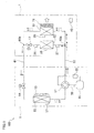
- the following describes an air conditioner 100 including a floor-placed indoor unit 1 related to an embodiment of the present invention.
- an air conditioner 100 of the present embodiment includes: a floor-placed indoor unit 1 (hereinafter, simply referred to as "indoor unit"), and an outdoor unit 5 installed outside a room.
- the indoor unit 1 includes: an indoor heat exchanger 22, a cross flow fan 21 disposed nearby the indoor heat exchanger 22, a radiation panel 30, an indoor motor-operated valve 17, and an indoor temperature sensor 46 configured to detect the indoor temperature.
- the outdoor unit 5 includes: a compressor 50, a four-way valve 51, an outdoor heat exchanger 52, an outdoor fan 53 disposed nearby the outdoor heat exchanger 52, and an outdoor motor-operated valve 54.
- the refrigerant circuit 60 has an annular principal channel 61 connected to the indoor heat exchanger 22, the compressor 50, the four-way valve 51, the outdoor heat exchanger 52, and the outdoor motor-operated valve 54.
- To the outdoor heat exchanger 52 is attached an outdoor heat exchanger temperature sensor 57.
- Branching sections 60a, 60b are provided to the conduits, which constitute the principal channel 61, on both sides of the indoor heat exchanger 22 in the indoor unit 1, respectively.
- the branching sections 60a and 60b are connected to ends of a bypass conduit 62, respectively.
- the conduits on both sides of the indoor heat exchanger 22 are connected through the bypass conduit 62.
- To this bypass conduit 62 are provided the radiation panel 30 and the indoor motor-operated valve 17.
- the bypass conduit 62 has a panel incoming temperature sensor 27 and a panel outgoing temperature sensor 28, which are disposed on both sides of the radiation panel 30, respectively. Further, an accumulator 55 is provided in the principal channel 61, between the intake side of the compressor 50 and the four-way valve 51, and a discharge temperature sensor 56 is provided between a discharge side of the compressor 50 and the four-way valve 51.
- the indoor heat exchanger 22 has a conduit constituting a part of the refrigerant circuit 60, and is provided with a temperature sensor 29.
- the indoor heat exchanger 22 is disposed on the windward side of the cross flow fan 21. The air heated or cooled by heat exchanging with the refrigerant flowing inside the indoor heat exchanger 22 is blown into the room as warm air or cool air by the cross flow fan 21, thereby performing warm-air heating or cooling.
- the radiation panel 30, as later-detailed, constitutes a part of the surface of the indoor unit 1, and has a panel conduit 33 (see FIG. 4 ) constituting a part of the refrigerant circuit 60.
- the heat of the refrigerant flowing in the panel conduit 33 is radiated into the room to perform radiation heating.
- the indoor motor-operated valve 17 is provided to adjust the flow rate of the refrigerant supplied to the radiation panel 30.
- the operation modes implemented in the air conditioner 100 of the present embodiment include a cooling mode, a warm-air heating mode, and a radiation heating mode.
- the cooling mode is a mode for performing cooling by causing the refrigerant to flow not in the radiation panel 30 but in the indoor heat exchanger 22.
- the warm-air heating mode is a mode for performing warm-air heating by causing the refrigerant to flow not in the radiation panel 30 but in the indoor heat exchanger 22.
- the radiation heating mode is a mode for performing radiation heating by causing the refrigerant to flow in the radiation panel 30, while causing the refrigerant to flow in the indoor heat exchanger 22 to perform warm-air heating.
- the indoor motor-operated valve 17 is opened and the four-way valve 51 is switched to a state shown by the solid line in FIG. 1 . Therefore, as shown by the solid-line arrow in FIG. 1 , the high-temperature, high-pressure refrigerant discharged from the compressor 50 flows in the indoor heat exchanger 22 through the four-way valve 51.
- the refrigerant condensed by the indoor heat exchanger 22 flows into the outdoor heat exchanger 52 after being decompressed by the outdoor motor-operated valve 54.
- the refrigerant vaporized in the outdoor heat exchanger 52 flows in the compressor 50 through the four-way valve 51 and accumulator 55.
- the indoor motor-operated valve 17 is opened and the four-way valve 51 is switched to a state shown by the solid line in FIG. 1 . Therefore, as shown by the broken-line arrow in FIG. 1 , the high-temperature, high-pressure refrigerant discharged from the compressor 50 flows in the indoor heat exchanger 22 and the radiation panel 30, through the four-way valve 51. The refrigerant condensed by the indoor heat exchanger 22 and the radiation panel 30 then flows in the outdoor heat exchanger 52 after being decompressed by the outdoor motor-operated valve 54. The refrigerant vaporized in the outdoor heat exchanger 52 flows in the compressor 50 through the four-way valve 51 and accumulator 55.
- the indoor unit 1 is to be set nearby a floor surface in a room and has, overall, a rectangular parallelepiped shape.
- the indoor unit 1 is attached to a wall surface, approximately 10cm above the floor surface.
- front the direction in which the indoor unit 1 projects from the wall on which the unit 1 is attached
- rear the direction opposite to the forward
- left and right directions shown in FIG. 2 are simply referred to as “horizontal direction” and the up and down directions are simply referred to as "vertical direction”.
- main components of the indoor unit 1 are a casing 10, the cross flow fan 21 accommodated in the casing 10, the indoor heat exchanger 22, internal devices such as an outlet port unit 25 and an electrical component unit 26, and a front grill 12.
- the casing 10 has a main inlet port 10a formed at the front side of its bottom, and auxiliary inlet ports 10b and 10c formed on its front wall. Further, on the upper end portion of the casing 10 is formed a discharge port 10d. Inside the casing 10 is formed a passage extended from the main inlet port 10a and the auxiliary inlet port 10b to the discharge port 10d.
- the air nearby the floor surface is sucked in through the main inlet port 10a and through the auxiliary inlet ports 10b and 10c.
- the air sucked in is conditioned by being heated or cooled in the indoor heat exchanger 22, and the conditioned air is returned by being blown into the room from the discharge port 10d.
- the casing 10 includes a body frame 11, an outlet port cover 41, a radiation panel 30, an opening-closing panel (opening-closing member) 42, and a side panel 15 (see FIG. 6 ).
- the outlet port cover 41 includes a front-surface panel section 41a
- the radiation panel 30 includes a front-surface panel section 31.
- the front-surface panel section 41a of the outlet port cover 41 and the front-surface panel section 31 and the opening-closing panel 42 of the radiation panel 30 are disposed so as to be flush with one another in a front surface of the casing 10, thus structuring the front-surface panel 4.
- a power button 18 and an emission display section 19 that indicates an operation status are provided in an upper right end portion of the front-surface panel 4, namely, in a right end portion of the front-surface panel section 41a of the outlet cover 41.
- the body frame 11 is to be attached to a wall surface, and supports various internal devices.
- the front grill 12, the outlet port cover 41, the radiation panel 30, and the opening-closing panel 42 are attached to the front surface of the body frame 11 which supports the internal devices.
- the outlet port cover 41 is attached to the upper end portion of the body frame 11, and a discharge port 10d that is a horizontally long rectangular opening is formed on the upper wall of the outlet cover 41.
- the radiation panel 30 is attached below the outlet port cover 41, and the opening-closing panel 42 is attached below the radiation panel 30.
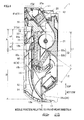
- the main inlet port 10a which is a horizontally long opening is formed between the lower front end of the body frame 11 and the lower end of the opening-closing panel 42. As shown in FIG. 4 , the main inlet port 10a is provided on the front side of a middle position, relative to the front-rear direction (i.e., the position indicated by an arrow), at the bottom end part of the casing 10.
- the cross flow fan 21 is disposed slightly above a central portion in a height direction of the casing 10 such that an axial direction of the cross flow fan 21 is in parallel to the horizontal direction.
- the cross flow fan 21 draws the air from the lower front and flows the air to the upper rear.
- the indoor heat exchanger 22 is disposed in substantially parallel to the front-surface panel 4, and includes a front-surface heat exchanger 22a facing the back surface of the front-surface panel 4, and a back-surface heat exchanger 22b that is upwardly inclined toward the back surface from the vicinity of the bottom end part of the front-surface heat exchanger 22a.
- the front-surface heat exchanger 22a is disposed in front of the cross flow fan 21, and the upper half thereof faces the cross flow fan 21. As shown in FIG. 4 , the upper end of the front-surface heat exchanger 22a is positioned higher than the upper end of the cross flow fan 21.
- the back-surface heat exchanger 22b is disposed below the cross flow fan 21. That is, the indoor heat exchanger 22 as a whole has a substantially V-shape, and is disposed so as to surround the front and lower sides of the cross flow fan 21, facing the cross flow fan 21.
- a length L1 of the front-surface heat exchanger 22a extended in the vertical direction is longer than a length L2 of the back-surface heat exchanger 22b inclined towards the back surface from the vicinity of the bottom end part of the front-surface heat exchanger 22a.
- the horizontal lengths of the front-surface heat exchanger 22a and the back-surface heat exchanger 22b when viewed from the front are substantially the same.
- the planar dimension of the portion where the air from the main inlet port 10a is supplied i.e., the planar dimension of the surface of the front-surface heat exchanger 22a facing the front is larger than the planar dimension of the portion of the back-surface heat exchanger 22b where the air from the main inlet port 10a is supplied, i.e., the planar dimension of the surface of the back-surface heat exchanger 22b facing lower rear side.
- conduits which supply the refrigerant from the outdoor unit 5 to the indoor heat exchanger 22 and the radiation panel 30. More specifically, in FIG. 1 , the conduits extending from the branching section 60a to the indoor heat exchanger 22 and the radiation panel 30, and the conduits extending from the indoor heat exchanger 22 and the radiation panel 30 to the branching section 60b are arranged on the right side of the indoor heat exchanger 22. As shown in FIG. 5 , a drip-resistant cover 23 is attached in front of these conduits.
- a drain pan 24 extended in the horizontal direction.
- the left end portion of the drain pan 24 is positioned so as to substantially face an end portion of the indoor heat exchanger 22, and the right end portion of the drain pan 24 is positioned so as to face the conduits arranged on the right side of the indoor heat exchanger 22.
- the end portions of the drain pan 24 relative to the front-rear direction are in positions that substantially face the end portions of the indoor heat exchanger 22 relative to the front-rear direction, respectively.
- the air drawn in through the main inlet port 10a is branched into the front side and the rear side under the drain pan 24, and is supplied to the front-surface heat exchanger 22a and the back-surface heat exchanger 22b.
- the outlet port unit 25 is disposed above the cross flow fan 21, and leads the air blown out from the cross flow fan 21 to the discharge port 10d formed at the upper end portion of the casing 10.
- the outlet port unit 25 includes a horizontal flap 25a disposed nearby the discharge port 10d.
- the horizontal flap 25a is configured to change the direction of the wind blown out from the discharge port 10d, relative to the vertical direction, and to open and close the discharge port 10d.
- the electrical component unit 26 is disposed below the drain pan 24, and includes an electric component box 26a which accommodates a circuit board (not shown) or the like, and a terminal stage 26b electrically connected to the circuit accommodated in the electric component box 26a.
- the electric component box 26a is disposed in a position substantially facing the right half portion of the indoor heat exchanger 22, and the terminal stage 26b is disposed in a position facing the conduits arranged on the right side of the indoor heat exchanger 22.
- a lead from the electrical component unit 26 is routed straight up from the right side of the terminal stage 26b, and connected to a power button 18 provided to the upper right end portion of the front-surface panel 4, and an LED luminous body of a light indicator 19.
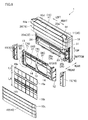
- the front grill 12 is attached to the body frame 11 to which the above-described internal devices, outlet port cover 41, and the radiation panel 30 are attached, as shown in FIG. 6 .
- the front grill 12 is attached so as to cover a range from the substantially central portion of the front-surface heat exchanger 22a in the vertical direction to the lower end of the body frame 11.
- the front grill 12 has, at its bottom end part, an inlet port grill 14 disposed at the main inlet port 10a.
- the portion of the front grill 12 covering the body frame 11 is provided with main guides 71 and 72 or the like which guide the upper filter 16a and the lower filter 16b, in cooperation with the main guide 72 or the like on the back surface of the radiation panel 30.
- the side panel 15 constituting a part of the side surface of the casing 10 is attached to the both, left and right sides of the front grill 12.
- each upper filter 16a there are four filters including two upper filters 16a arranged side-by-side on the left and right and two lower filters 16b arranged below the upper filters 16a.
- the length L3 of each upper filter 16a relative to the vertical direction is shorter than the length L4 of each lower filter 16b relative to the vertical direction.
- the width of each upper filter 16a (length relative to the horizontal direction) is substantially the same as that of the lower filter 16b. In short, the planar dimension of each upper filter 16a is smaller than that of each lower filter 16b.
- each upper filter 16a there are four filters including two upper filters 16a arranged side-by-side on the left and right and two lower filters 16b arranged below the upper filters 16a.
- the length L1 of each upper filter 16a relative to the vertical direction is shorter than the length L2 of each lower filter 16b relative to the vertical direction.
- the width of each upper filter 16a (length relative to the horizontal direction) is substantially the same as that of the lower filter 16b. In short, the planar dimension of each upper filter 16a is smaller than that of each lower filter 16b.
- the upper filters 16a and the lower filters 16b are provided in a space between the front-surface heat exchanger 22a and the front-surface panel 4, i.e., in a passage from the main inlet port 10a and the auxiliary inlet ports 10b and 10c to the front-surface heat exchanger 22a.
- the upper filters 16a extended in the vertical direction are mounted in an upper filter mounting region (region indicated by A) as shown in FIG. 4 , and their lower ends face a portion of the front-surface heat exchanger 22a, which is substantially in the middle relative to the vertical direction.
- the lower filters 16b are mounted in a lower filter mounting region (region indicated by B) as shown in FIG. 4 , and extends downward from the vicinity of the lower end of the upper filters 16a.
- each lower filter 16b is curved to form a convex towards front.
- a portion of each lower filter 16b below the drain pan 24 arranged nearby the bottom end part of the indoor heat exchanger 22 is curved.
- the lower end of each lower filter 16b is positioned nearby the rear end of the main inlet port 10a.
- the cross-hatched region corresponds to the upper filter mounting region for arranging the left side upper filter 16a.
- the dot-hatched region in the figure corresponds to the lower filter mounting region for arranging therein the left side lower filter 16b.
- the radiation panel 30 covers most of the upper end of the upper filter mounting region (i.e., region excluding the bottom end part, with reference symbol a1 in FIG. 11 ).
- the radiation panel 30 corresponds to an outer periphery of the present invention.
- the bottom end part of the upper filter mounting region (region given a reference symbol of a2 in FIG. 11 ) and the lower filter mounting region face the opening-closing panel 42. Therefore, while the opening-closing panel 42 is detached as shown in FIG. 11 , the bottom end part of the upper filter mounting region and the lower filter mounting region are exposed.
- the upper filter 16a is inserted upward from the region a2 at the bottom end part of its mounting region.
- the lower filter 16b on the other hand is inserted downward from the upper end portion of its mounting region.
- the front grill 12 has main guides 71 constituting a part of the upper filter guiding member 70 for guiding the upper filter 16a and main guides 81 and auxiliary guides 82 constituting the lower filter guiding member 80 for guiding the lower filter 16b.
- the main guides 71 and 81 are each provided on the rear side of wall surfaces 13 provided on the left and right sides of the upper filter mounting region and the lower filter mounting region, and the auxiliary guides 82 are provided on the front side of the wall surfaces 13.
- the main guides 71 and 81 and the auxiliary guides 82 are all formed so as to project towards the upper filter mounting region or the lower filter mounting region from the wall surfaces 13.
- the main guides 71 and 81 and the auxiliary guides 82 are detailed later.
- the outlet port cover 41 covers the outlet port unit 25.
- the discharge port 10d is formed on the upper wall of the outlet port cover 41.
- the front-surface panel section 41a is formed on the front side of the outlet port cover 41.
- the front-surface panel section 41a has a rectangular shape which is long in the horizontal direction. As shown in FIG. 3 , the length of the front-surface panel section 41a relative to the vertical direction is defined as L.
- the radiation panel 30 has a substantially rectangular shape long in the horizontal direction, and is provided on the upper side of the central portion of the casing 10 relative to the vertical direction.
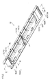
- the radiation panel 30 mainly has an aluminum-made front-surface panel section 31, a resin-made insulation cover 32 attached so as to cover the back surface of the front-surface panel section 31, and a panel conduit 33 attached to and in contact with the back surface of the front-surface panel section 31.
- the panel conduit 33 is a part of the conduits constituting the refrigerant circuit 60.
- the refrigerant sent from the outdoor unit 5 flows into the panel conduit 33, and flows from the right end portion to the left end portion on the back surface of the front-surface panel section 31, when viewed from the front.
- the refrigerant then flows from the left end portion to the right end portion, and flows out of the panel conduit 33 from the right end portion.
- the length of the front-surface panel section 31 relative to the vertical direction is approximately twice the length of the front-surface panel section 41a of the outlet port cover 41. In other words, the length of the front-surface panel section 31 relative to the vertical direction is approximately 2L, as shown in FIG. 3 .
- the front-surface panel section 31 is positioned below the front-surface panel section 41a of the outlet port cover 41. As shown in FIG. 4 , the substantially middle part of the radiation panel 30 relative to the vertical direction faces the upper end portion of the front-surface heat exchanger 22a.
- main guides 72 and auxiliary guides 73 which constitute a part of the upper filter guiding member 70 for guiding the upper filter 16a.
- the main guides 72 are shown by a broken line in FIG. 11 .
- the main guides 72 are positioned above the main guides 71 provided to the front grill 12.
- the main guides 72 are provided on the rear side of a wall surface 34 on the left and right sides of the upper filter mounting region, and the auxiliary guides 73 are provided on the front side of the wall surfaces 34.
- the main guides 72 and the auxiliary guides 73 are both formed so as to project towards the upper filter mounting region from the wall surfaces 34.
- the main guides 72 and the auxiliary guides 73 are detailed later.
- the opening-closing panel 42 is provided below the front-surface panel section 31 of the radiation panel 30 so as to be opened or closed.
- the opening-closing panel 42 has a rectangular shape which is long in the horizontal direction, and its length relative to the vertical direction is approximately four times the length of the front-surface panel section 41a of the outlet port cover 41. In other words, the length of the opening-closing panel 42 relative to the vertical direction is approximately 4L, as shown in FIG. 3 .
- the position of the upper end of the opening-closing panel 42 relative to the vertical direction is substantially the same as that of the upper end of the front grill 12.
- the lower end of the opening-closing panel 42 constitutes a part of the main inlet port 10a.
- detaching the opening-closing panel 42 exposes the bottom end part (region a2) of the upper filter mounting region and the lower filter mounting region (region B) provided on the front grill 12, and allows insertion of the upper filters 16a and the lower filters 16b.
- the front-surface panel 4 includes the front-surface panel section 41a provided to the outlet port cover 41, the front-surface panel section 31 of the radiation panel 30, and the opening-closing panel 42, as is already mentioned. Between the front-surface panel section 31 of the radiation panel 30 and the opening-closing panel 42 is formed the auxiliary inlet port 10b which is an opening in the form of a slit extended in the left and right direction (horizontal direction). Further, nearby the upper end of the opening-closing panel 42 is formed the auxiliary inlet port 10c which is an opening in the form of a slit extended in the horizontal direction. As shown in FIG. 3 , the distance from the upper end of the opening-closing panel 42 to the auxiliary inlet port 10c, relative to the vertical direction is L.
- the length of the front-surface panel 4 relative to the vertical direction is 7L
- the auxiliary inlet port 10b is in a position 3L from the upper end of the front-surface panel 4
- the auxiliary inlet port 10c is in a position 3L from the lower end of the front-surface panel 4.
- the auxiliary inlet ports 10b and 10c are provided in the middle portion of the front-surface panel 4 relative to the vertical direction (height direction).
- the auxiliary inlet ports 10b and 10c face the front-surface heat exchanger 22a, as shown in FIG. 4 .
- the upper filter guiding member 70 is provided to the upper filter mounting region for each of the two upper filters 16a arranged side-by-side on the left and right, and is configured to guide the upper filter 16a.
- the upper filter guiding member 70 includes the main guides 71 provide to the front grill 12, the wall surfaces 13 which are a part of the front grill 12, the main guides 72 and the auxiliary guides 73 provided to the radiation panel 30, and the wall surfaces 34 which are a part of the radiation panel 30.
- the main guides 71 and 72 correspond to a first guide unit of the present invention.
- the main guides 71 are formed on the upper end portion of the front grill 12, and are substantially parallel to a filter surface of the upper filter 16a guided by the upper filter guiding member 70.
- the main guides 71 guide the left and right end portions of the upper filter 16a, at the beginning of inserting the upper filter 16a.
- the main guides 71 correspond to the insertion start unit of the first guide unit. More specifically, the main guides 71 abut the back surface of the left and right end portions of the upper filter 16a, and along with the wall surfaces 13 of the front grill 12, regulate an insertion direction of the upper filter 16a.
- the main guides 72 guide the left and right end portions of the upper filter 16a, in a position above the main guides 71 (downstream side of the main guides 71 relative to the insertion direction of the upper filter 16a), and are substantially parallel to the filter surface of the upper filter 16a. More specifically, the main guides 72 abut the back surface of the left and right end portions of the upper filter 16a, and along with the wall surfaces 34 of the radiation panel 30, regulate the insertion direction of the upper filter 16a.
- the auxiliary guides 73 are formed in front of the main guides 72. As shown in FIG. 8 and FIG. 9 , the upper halves of the auxiliary guides 73 extend in the vertical direction, and the lower halves of the auxiliary guides 73 are tilted towards the front. This way, the upper parts of the left and right end portions of the upper filter 16a mounted to the upper filter guiding member 70 are sandwiched between the main guides 72 and the auxiliary guides 73. Note that the lower ends of the auxiliary guides 73 match with the lower front end of the insulation cover 32. Therefore, when the upper filter 16a is inserted upward from the lower side of the radiation panel 30, the upper filter 16a is prevented from departing from the insertion path.
- the auxiliary guides 73 extended to the lower front end of the insulation cover 32 prevent the upper filter 16a from going into a region in front of the auxiliary guides 73.
- the lower filter guiding member 80 is provided to the upper filter mounting region for each of the two lower filters 16b arranged side-by-side on the left and right, and is configured to guide the lower filter 16b.
- the lower filter guiding member 80 includes the main guides 81 and the auxiliary guides 82 provided to the front grill 12, and the wall surfaces 13 which are a part of the front grill 12.
- the main guides 81 extend from the bottom end part of the front grill 12 to the lower ends of the main guides 71, and are substantially parallel to a filter surface of the lower filter 16b guided by the lower filter guiding member 80.
- the main guides 81 abut the back surface of the left and right end portions of the lower filter 16b, and along with the wall surfaces 13 of the front grill 12, regulate an insertion direction of the lower filter 16b.
- the main guides 81 correspond to the second guide unit of the present invention.
- the upper halves of the main guides 81 extend in the vertical direction, and the lower halves of the main guides 81 are curved to form a convex towards front.
- the auxiliary guides 82 are provided in front of the curved portions of the main guides 81. This way, the left and right end portions of the lower half of the lower filter 16b to be mounted to the lower filter guiding member 80 are sandwiched between the main guides 81 and the auxiliary guides 82 and are curved to form a convex towards front.
- the guide width of the upper filter guiding member 70 and the lower filter guiding member 80 are described with reference to FIG. 12 .
- the guide width is a total width of portions of the upper filter guiding member 70 or the lower filter guiding member 80, which are substantially parallel to the filter surface and which guide the left and right end portions of the upper filter 16a or the lower filter 16b.
- the guide width of the insertion start unit (region a2) of the upper filter guiding member 70 is the total width of the main guides 71 in the upper filter mounting region, which abut the back surfaces of the left and right end portions of the upper filter 16a and regulate the insertion direction of the filter.
- the guide width of a portion (region a1) at the downstream side of the insertion start unit of the upper filter guiding member 70, relative to the filter insertion direction is a total width of the main guides 72 in the upper filter mounting region, which abut the back surface s of the left and right end portions of the upper filter 16a to regulate the filter insertion direction.
- the guide width of the lower filter guiding member 80 i.e., the guide width of the region B which is the lower filter mounting region
- the width of the main guide 71 at the left end portion of the upper filter mounting region (region A) is W1.
- the width of each main guide 71 provided to the left and right end portions of the upper filter mounting region is the same. Therefore, the guide width of the insertion start unit (region a2) for the upper filter guiding member 70 is 2 ⁇ W1.
- the width of the main guide 72 at the left end portion of the upper filter mounting region (region A) and that of the main guide 81 at the left end portion of the lower filter mounting region (region B) are substantially the same and are both W2.
- the respective widths of the main guides 72 on the left and right end portions of the region A, and the respective widths of the main guides 81 on the left and right end portions of the region B are all the same. Therefore, guide width of the portion (region a1) at the downstream side of the insertion start unit of the upper filter guiding member 70 relative to the filter insertion direction and the guide width of the lower filter mounting region (region B) are both 2xW2.
- the guide width (2 ⁇ W1) in the region a2 which is the insertion start unit of the upper filter guiding member 70 is greater than the guide width (2xW2) which is the guide width of the region a1 at the downstream side of the insertion start unit of the upper filter guiding member 70 relative to the insertion direction and the guide width of the region B which is the lower filter mounting region.
- each of the main guides 72 and 81 is substantially the same as the width of each of the frames at the left and right end portions of the upper filter 16a and the lower filter 16b. Further, the width of each of the auxiliary guides 73 and 82 arranged in positions to face the main guides 72 and 81, respectively, is substantially the same as the width W2 of each of the main guides 72 and 81.
- the upper filter 16a and the lower filter 16b are mounted to the upper filter guiding member 70 and the lower filter guiding member 80, respectively, it is possible to prevent an increase in the ventilation resistance by the main guides 72 and 81 or the auxiliary guides 73 and 82, and to prevent a decrease in the area of the upper filter 16a and the lower filter 16b for filtering the dusts.
- FIG. 13 a procedure for mounting the lower filter 16b is described with reference to FIG. 13 .
- the opening-closing panel 42 is detached to enable insertion of the filter. This exposes the region B which is the lower filter 16b mounting region.
- FIG. 13 (a) the back surfaces of the left and right end portions of the lower part of the upper filter 16a are brought into contact with the upper end portions of the main guides 81 of the lower filter guiding member 80.
- the insertion direction of the lower filter 16b is regulated by the main guides 81 and the wall surfaces 13 of the front grill 12.
- the lower filter 16b whose insertion direction is regulated as described above is inserted in the insertion direction (downwards).
- the left and right end portions of the lower filter 16b are sandwiched between the main guides 81 and the auxiliary guides 82, and are bent to form a convex towards front.
- the lower filter 16b is inserted until the entire lower filter 16b is inside the region B which is the filter mounting region. The lower half of the lower filter 16b at this time forms a convex towards front.
- An indoor unit 1 of the present embodiment includes an upper filter 16a and a lower filter 16b in a passage extended from the main inlet port 10a provided at the front side of the bottom end part of the casing 10 to the front-surface heat exchanger 22a of the indoor heat exchanger 22.
- the lower filter 16b is arranged so that its portion lower than the front-surface heat exchanger 22a is curved at least in part to form a convex towards the front. This, unlike the cases where the lower filter 16b has no curvature, reduces the ventilation resistance with an increased planar dimension of the portion of the upper filter 16a lower than the front-surface heat exchanger 22a.
- the above structure facilitates the flow of air drawn in from the main inlet port 10a at the front side of the bottom end part of the casing 10 to the back surface through the upper filter 16a, below the front-surface heat exchanger 22a.
- shortage in the air supply to the back-surface heat exchanger 22b is restrained, and the heat exchanging efficiency of the indoor heat exchanger 22 is kept from lowering.
- the indoor unit 1 of the present embodiment includes a drain pan 24 provided below the indoor heat exchanger 22.
- a drain pan 24 When there is a drain pan 24, the flow of the air to the back-surface heat exchanger 22b is made difficult due to the presence of the drain pan 24. For this reason, application of the present invention to such a case is effective.
- the front-surface heat exchanger 22a is substantially parallel to the front-surface panel 4. This reduces the resistance against the airflow generated between the front-surface panel 4 and the front-surface heat exchanger 22a, as compared with the cases where the front-surface heat exchanger 22a is tilted relative to the front-surface panel 4.
- the planar dimension of the front-surface heat exchanger 22a is larger than that of the back-surface heat exchanger 22b.
- the amount of air flowing to the back-surface heat exchanger 22b with a relatively small planar dimension tends to be smaller than that flows to the front-surface heat exchanger 22a. As such, application of the present invention to such a case is effective.
- the indoor unit 1 of the present embodiment includes a cross flow fan 21 disposed to face the front-surface heat exchanger 22a and the back-surface heat exchanger 22b within the casing 10. Therefore, the air drawn in from the main inlet port 10a with driving of the cross flow fan 21 is supplied to the front-surface heat exchanger 22a and the back-surface heat exchanger 22b.
- the indoor unit 1 of the present embodiment includes main guides 81 and the auxiliary guides 82 configured to cause a portion of the lower filter 16b lower than the front-surface heat exchanger 22a to be curved at least in part to form a convex towards front.
- the lower filter 16b therefore is reliably curved by the main guides 81 and the auxiliary guides 82.
- the above embodiment deals with a case where a portion of the lower filter 16b lower than the drain pan 24 is curved to form a convex to the front; however, the portion of the lower filter 16b curved is not limited to that portion, as long as the portion of the filter lower than the front-surface heat exchanger 22a is curved at least in part to form a convex towards front.
- the main inlet port 10a is formed between the lower front end of the body frame 11 and the lower end of the front-surface panel 4, and is positioned on the front side of the middle position, relative to the front-rear direction, of the bottom end part of the casing 10; however, the position of the main inlet port 10a is not limited to this.
- the main inlet port 10a may be formed so as to cross the middle position, relative to the front-rear direction, of the bottom end part of the casing 10, provided that the portion of the main inlet port 10a on the front side of the middle position is larger than the portion on the rear side.
- the main inlet port 10a may be formed on the front-surface panel 4, or formed on the front-surface panel 4 and on the bottom wall of the casing 10.
- the above embodiment deals with a case where the front-surface heat exchanger 22a is substantially parallel to the front-surface panel 4; however, the front-surface heat exchanger 22a may be tilted with respect to the front-surface panel 4.
- the above embodiment deals with a case where the planar dimension of the front-surface heat exchanger 22a is greater than that of the back-surface heat exchanger 22b; however, the planar dimension of the front-surface heat exchanger 22a may be equal to or smaller than that of the back-surface heat exchanger 22b.
- the above embodiment deals with a case of including a cross flow fan 21 disposed to face the front-surface heat exchanger 22a and the back-surface heat exchanger 22b; however, the present invention is not limited to this.
- a turbofan or the like may be adopted in place of the cross flow fan 21.
- the above embodiment deals with a case of including the main guides 81 and the auxiliary guides 82 which causes the portion of the lower filter 16b lower than the front-surface heat exchanger 22a to curve to form a convex towards front side; however, the present invention is not limited to this.
- these guides for bending the lower filter 16b are not necessary, if the lower filter 16b is curved.
- the above embodiment deals with a case where the floor-placed indoor unit 1 is set on a wall surface, 10cm above the floor surface; however, the present invention is not limited to this.
- the present invention may be applied to floor-placed indoor units in general which are set in the vicinity of the floor surface.
- the present invention may be applied to the floor-placed indoor unit which is set on the floor surface.
- the present invention prevents the heat exchanging efficiency from being lowered.
Landscapes
- Engineering & Computer Science (AREA)
- Chemical & Material Sciences (AREA)
- Combustion & Propulsion (AREA)
- Mechanical Engineering (AREA)
- General Engineering & Computer Science (AREA)
- Life Sciences & Earth Sciences (AREA)
- Sustainable Development (AREA)
- Air Filters, Heat-Exchange Apparatuses, And Housings Of Air-Conditioning Units (AREA)
- Devices For Blowing Cold Air, Devices For Blowing Warm Air, And Means For Preventing Water Condensation In Air Conditioning Units (AREA)
Abstract
Description
- The present invention relates to a floor-placed indoor unit including a substantially V-shaped heat exchanger having a front-surface heat exchanger and a back-surface heat exchanger.
- There has traditionally been a floor-placed indoor unit which sucks the air nearby the floor surface through the inlet port provided to a bottom end part of a casing, and then blows out the air from the discharge port provided to an upper end portion of the casing (e.g., see Patent Literature 1). The air sucked through the inlet port is fed to the heat exchanger accommodated in the casing and heated by means of heat exchanging with the refrigerant flowing in the heat exchanger. Then, heated air is blown out from the discharge port.
- [Patent Literature 1] Japanese Laid-Open Utility Model Publication No.
185023/1988 Jitsukaishou 63-185023 - The floor-placed indoor unit having the above structure may adopt a substantially V-shaped heat exchanger having a front-surface heat exchanger disposed so as to face the back surface of the front-surface panel of the casing, and a back-surface heat exchanger that tilts upward with proximity to the back surface from the vicinity of the bottom end of the front-surface heat exchanger. When such a heat exchanger is adopted, it is more difficult to cause the air sucked in from the inlet port provided at the front side of the bottom end part of the casing to flow to the side of the back-surface heat exchanger, as compared with a case of causing the air to flow to the side of the front-surface heat exchanger. Enough air therefore is not supplied to the back-surface heat exchanger, which leads to a problem that the heat exchanging efficiency of the heat exchanger may be lowered.
- To solve the above problem, the present invention was made and it is an object of the present invention to provide a floor-placed indoor unit in which deterioration of the heat exchanging efficiency is prevented.
- A first aspect of the present invention is a floor-placed indoor unit, including: a casing having a front-surface panel and accommodating therein a heat exchanger; an inlet port formed at the front side of the bottom end part of the casing, which draws in air nearby a floor surface; a discharge port configured to blow out air, which is provided at an upper end portion of the casing; and a filter provided in a passage extending from the inlet port to the heat exchanger within the casing, wherein the heat exchanger includes a front-surface heat exchanger disposed to face a back surface of the front-surface panel, a back-surface heat exchanger tilted upward from the lower end of the front-surface heat exchanger towards a rear side, and wherein the filter is inserted between the front-surface panel and the front-surface heat exchanger, and a portion of the filter lower than the front-surface heat exchanger is curved at least in part to form a convex towards front.
- The "(inlet port) formed at the front side of the bottom end part of the casing" means that, of the inlet port formed at the front side of the bottom end part of the casing, a portion formed on the front side of the middle position, relative to the front-rear direction, of the bottom of the casing is greater than a portion formed on the rear-side.
- Unlike the cases where the filter in the passage from the inlet port to the back-surface heat exchanger has no curvature, the floor-placed indoor unit described above reduces the ventilation resistance with an increased planar dimension of the portion of the filter lower than the front-surface heat exchanger. The structure facilitates the flow of air drawn in from the inlet port provided at the front side of the bottom end part of the casing to the back surface side through the filter positioned below the front-surface heat exchanger. Thus, shortage in the air supply to the back-surface heat exchanger is restrained, and the heat exchanging efficiency of the heat exchanger is kept from lowering.
- A second aspect of the present invention is the floor-placed indoor unit of the first aspect, further including a drain pan provided below the heat exchanger.
- When the floor-placed indoor unit has a drain pan, the flow of air to the back-surface heat exchanger is made difficult due to the presence of the drain pan. For this reason, application of the present invention to such a case is effective.
- A third aspect of the present invention is the floor-placed indoor unit of the first or the second aspect, adapted so that the front-surface heat exchanger is substantially parallel to the front-surface panel.
- This floor-placed indoor unit reduces resistance against the airflow generated between the front-surface panel and the front-surface heat exchanger, as compared with the cases where the front-surface heat exchanger is tilted relative to the front-surface panel.
- A fourth aspect of the present invention is the floor-placed indoor unit of any one of the first to the third aspects, adopted so that the planar dimension of the front-surface heat exchanger is greater than that of the back-surface heat exchanger.
- In a floor-placed indoor unit, the amount of air flowing to the back-surface heat exchanger with a relatively small planar dimension tends to be smaller than that flows to the front-surface heat exchanger. As such, application of the present invention to such a case is effective.
- A fifth aspect of the present invention is the floor-placed indoor unit of any one of the first to the fourth aspects, further including a cross flow fan disposed to face the front-surface heat exchanger and the back-surface heat exchanger, within the casing.
- In this floor-placed indoor unit, the air drawn in from the inlet port with driving of the cross flow fan is supplied to the front-surface heat exchanger and the back-surface heat exchanger.
- A sixth aspect of the present invention is the floor-placed indoor unit of any one of the first to sixth aspects, further including a guide unit configured to cause the portion of the filter lower than the front-surface heat exchanger to be curved at least in part to form a convex towards front.
- Therefore, in the floor-placed indoor unit, the filter is reliably curved by the guide unit.
- As hereinabove described, the present invention brings about the following advantageous effects.
- Unlike the cases where the filter in the passage from the inlet port to the back-surface heat exchanger has no curvature, the first aspect of the present invention reduces the ventilation resistance with an increased planar dimension of the portion of the filter lower than the front-surface heat exchanger. The structure facilitates the flow of air drawn in from the inlet port at the front side of the bottom end part of the casing to the back surface side through the filter positioned below the front-surface heat exchanger. Thus, shortage in the air supply to the back-surface heat exchanger is restrained, and the heat exchanging efficiency of the heat exchanger is kept from lowering.
- The flow of air to the back-surface heat exchanger had been made difficult when there is a drain pan in the floor-placed indoor unit, as in the case of the second aspect of the present invention. Application of the present invention is therefore effective.
- This third aspect of the present invention reduces resistance against the airflow generated between the front-surface panel and the front-surface heat exchanger, as compared with the cases where the front-surface heat exchanger is tilted relative to the front-surface panel.
- In a floor-placed indoor unit, the amount of air flowing to the back-surface heat exchanger with a relatively small planar dimension, as in the case with the fourth aspect of the present invention, tends to be smaller than that flows to the front-surface heat exchanger. As such, application of the present invention to such a case is effective.
- In the fifth aspect of the present invention, the air drawn in from the inlet port with driving of the cross flow fan is supplied to the front-surface heat exchanger and the back-surface heat exchanger.
- With the sixth aspect of the present invention, the filter is reliably curved by the guide unit.
-
- [
FIG. 1] FIG. 1 is a circuit diagram of an air conditioner having a floor-placed indoor unit related to an embodiment of the present invention. - [
FIG. 2] FIG. 2 is a perspective diagram of the floor-placed indoor unit shown inFIG. 1 . - [
FIG. 3] FIG. 3 is a front view of the floor-placed indoor unit shown inFIG. 1 . - [
FIG. 4] FIG. 4 is a cross sectional view of the floor-placed indoor unit, taken along the line IV-IV inFIG. 3 . - [
FIG. 5] FIG. 5 is a diagram showing the floor-placed indoor unit shown inFIG. 3 , with its front grill or opening-closing panel being detached. - [
FIG. 6] FIG. 6 is an exploded perspective diagram of the floor-placed indoor unit in the state shown inFIG. 5 , along with its front grill, side cover, upper filter, lower filter, and opening-closing panel. - [
FIG. 7] FIG. 7 is an enlarged view of a portion encircled by a dotted line inFIG. 6 . - [
FIG. 8] FIG. 8 is a perspective diagram of the back surface of an insulation cover shown inFIG. 4 . - [
FIG. 9] FIG. 9 is a cross sectional view of the insulation cover, taken along the line IX-IX inFIG. 8 . - [
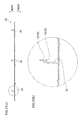
FIG. 10] FIG. 10 (a) is a cross sectional view of the insulation cover, taken along the line X-X inFIG. 8 , andFIG. 10 (b) is an enlarged view of a portion encircled by a dotted line inFIG. 10 (a) . - [
FIG. 11] FIG. 11 is a schematic diagram showing the state in which t opening-closing panel of the floor-placed indoor unit shown inFIG. 3 is detached. - [
FIG. 12] FIG. 12 is a schematic diagram of a main guide provided to the both front grill and the radiation panel shown inFIG. 11 . - [
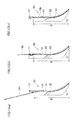
FIG. 13] FIG. 13 is a diagram for explaining steps of attaching the lower filter to a lower filter guiding member shown inFIG. 12 . - The following describes an air conditioner 100 including a floor-placed
indoor unit 1 related to an embodiment of the present invention. - As shown in
FIG. 1 , an air conditioner 100 of the present embodiment includes: a floor-placed indoor unit 1 (hereinafter, simply referred to as "indoor unit"), and anoutdoor unit 5 installed outside a room. Theindoor unit 1 includes: anindoor heat exchanger 22, across flow fan 21 disposed nearby theindoor heat exchanger 22, aradiation panel 30, an indoor motor-operatedvalve 17, and anindoor temperature sensor 46 configured to detect the indoor temperature. Further, theoutdoor unit 5 includes: acompressor 50, a four-way valve 51, anoutdoor heat exchanger 52, anoutdoor fan 53 disposed nearby theoutdoor heat exchanger 52, and an outdoor motor-operatedvalve 54. - The
refrigerant circuit 60 has anannular principal channel 61 connected to theindoor heat exchanger 22, thecompressor 50, the four-way valve 51, theoutdoor heat exchanger 52, and the outdoor motor-operatedvalve 54. To theoutdoor heat exchanger 52 is attached an outdoor heatexchanger temperature sensor 57. Branchingsections principal channel 61, on both sides of theindoor heat exchanger 22 in theindoor unit 1, respectively. The branchingsections bypass conduit 62, respectively. In other words, the conduits on both sides of theindoor heat exchanger 22 are connected through thebypass conduit 62. To thisbypass conduit 62 are provided theradiation panel 30 and the indoor motor-operatedvalve 17. Thebypass conduit 62 has a panelincoming temperature sensor 27 and a paneloutgoing temperature sensor 28, which are disposed on both sides of theradiation panel 30, respectively. Further, anaccumulator 55 is provided in theprincipal channel 61, between the intake side of thecompressor 50 and the four-way valve 51, and adischarge temperature sensor 56 is provided between a discharge side of thecompressor 50 and the four-way valve 51. - The
indoor heat exchanger 22 has a conduit constituting a part of therefrigerant circuit 60, and is provided with atemperature sensor 29. Theindoor heat exchanger 22 is disposed on the windward side of thecross flow fan 21. The air heated or cooled by heat exchanging with the refrigerant flowing inside theindoor heat exchanger 22 is blown into the room as warm air or cool air by thecross flow fan 21, thereby performing warm-air heating or cooling. - The
radiation panel 30, as later-detailed, constitutes a part of the surface of theindoor unit 1, and has a panel conduit 33 (seeFIG. 4 ) constituting a part of therefrigerant circuit 60. The heat of the refrigerant flowing in thepanel conduit 33 is radiated into the room to perform radiation heating. The indoor motor-operatedvalve 17 is provided to adjust the flow rate of the refrigerant supplied to theradiation panel 30. - The operation modes implemented in the air conditioner 100 of the present embodiment include a cooling mode, a warm-air heating mode, and a radiation heating mode. The cooling mode is a mode for performing cooling by causing the refrigerant to flow not in the
radiation panel 30 but in theindoor heat exchanger 22. The warm-air heating mode is a mode for performing warm-air heating by causing the refrigerant to flow not in theradiation panel 30 but in theindoor heat exchanger 22. The radiation heating mode is a mode for performing radiation heating by causing the refrigerant to flow in theradiation panel 30, while causing the refrigerant to flow in theindoor heat exchanger 22 to perform warm-air heating. - During the warm-air heating mode, the indoor motor-operated
valve 17 is opened and the four-way valve 51 is switched to a state shown by the solid line inFIG. 1 . Therefore, as shown by the solid-line arrow inFIG. 1 , the high-temperature, high-pressure refrigerant discharged from thecompressor 50 flows in theindoor heat exchanger 22 through the four-way valve 51. The refrigerant condensed by theindoor heat exchanger 22 flows into theoutdoor heat exchanger 52 after being decompressed by the outdoor motor-operatedvalve 54. The refrigerant vaporized in theoutdoor heat exchanger 52 flows in thecompressor 50 through the four-way valve 51 andaccumulator 55. - During the radiation heating mode, the indoor motor-operated
valve 17 is opened and the four-way valve 51 is switched to a state shown by the solid line inFIG. 1 . Therefore, as shown by the broken-line arrow inFIG. 1 , the high-temperature, high-pressure refrigerant discharged from thecompressor 50 flows in theindoor heat exchanger 22 and theradiation panel 30, through the four-way valve 51. The refrigerant condensed by theindoor heat exchanger 22 and theradiation panel 30 then flows in theoutdoor heat exchanger 52 after being decompressed by the outdoor motor-operatedvalve 54. The refrigerant vaporized in theoutdoor heat exchanger 52 flows in thecompressor 50 through the four-way valve 51 andaccumulator 55. - The following describes a structure of the
indoor unit 1. As shown inFIG. 2 , theindoor unit 1 is to be set nearby a floor surface in a room and has, overall, a rectangular parallelepiped shape. In the present embodiment, theindoor unit 1 is attached to a wall surface, approximately 10cm above the floor surface. In the following description, the direction in which theindoor unit 1 projects from the wall on which theunit 1 is attached is referred to as "front", and the direction opposite to the forward is referred to as "rear". Further, the left and right directions shown inFIG. 2 are simply referred to as "horizontal direction" and the up and down directions are simply referred to as "vertical direction". - As shown in
FIG. 4 , main components of theindoor unit 1 are acasing 10, thecross flow fan 21 accommodated in thecasing 10, theindoor heat exchanger 22, internal devices such as anoutlet port unit 25 and anelectrical component unit 26, and afront grill 12. As hereinafter detailed, thecasing 10 has amain inlet port 10a formed at the front side of its bottom, andauxiliary inlet ports casing 10 is formed adischarge port 10d. Inside thecasing 10 is formed a passage extended from themain inlet port 10a and theauxiliary inlet port 10b to thedischarge port 10d. In theindoor unit 1, when thecross flow fan 21 is driven, the air nearby the floor surface is sucked in through themain inlet port 10a and through theauxiliary inlet ports indoor heat exchanger 22, and the conditioned air is returned by being blown into the room from thedischarge port 10d. - The
casing 10 includes abody frame 11, anoutlet port cover 41, aradiation panel 30, an opening-closing panel (opening-closing member) 42, and a side panel 15 (seeFIG. 6 ). As described in detail later, theoutlet port cover 41 includes a front-surface panel section 41a, and theradiation panel 30 includes a front-surface panel section 31. The front-surface panel section 41a of theoutlet port cover 41 and the front-surface panel section 31 and the opening-closingpanel 42 of theradiation panel 30 are disposed so as to be flush with one another in a front surface of thecasing 10, thus structuring the front-surface panel 4. As shown inFig. 2 , apower button 18 and anemission display section 19 that indicates an operation status are provided in an upper right end portion of the front-surface panel 4, namely, in a right end portion of the front-surface panel section 41a of theoutlet cover 41. - The
body frame 11 is to be attached to a wall surface, and supports various internal devices. Thefront grill 12, theoutlet port cover 41, theradiation panel 30, and the opening-closingpanel 42 are attached to the front surface of thebody frame 11 which supports the internal devices. Theoutlet port cover 41 is attached to the upper end portion of thebody frame 11, and adischarge port 10d that is a horizontally long rectangular opening is formed on the upper wall of theoutlet cover 41. Theradiation panel 30 is attached below theoutlet port cover 41, and the opening-closingpanel 42 is attached below theradiation panel 30. Themain inlet port 10a which is a horizontally long opening is formed between the lower front end of thebody frame 11 and the lower end of the opening-closingpanel 42. As shown inFIG. 4 , themain inlet port 10a is provided on the front side of a middle position, relative to the front-rear direction (i.e., the position indicated by an arrow), at the bottom end part of thecasing 10. - The following describes each internal device accommodated in the
casing 10.
The cross flowfan 21 is disposed slightly above a central portion in a height direction of thecasing 10 such that an axial direction of thecross flow fan 21 is in parallel to the horizontal direction. The cross flowfan 21 draws the air from the lower front and flows the air to the upper rear. - The
indoor heat exchanger 22 is disposed in substantially parallel to the front-surface panel 4, and includes a front-surface heat exchanger 22a facing the back surface of the front-surface panel 4, and a back-surface heat exchanger 22b that is upwardly inclined toward the back surface from the vicinity of the bottom end part of the front-surface heat exchanger 22a. The front-surface heat exchanger 22a is disposed in front of thecross flow fan 21, and the upper half thereof faces thecross flow fan 21. As shown inFIG. 4 , the upper end of the front-surface heat exchanger 22a is positioned higher than the upper end of thecross flow fan 21. The back-surface heat exchanger 22b is disposed below thecross flow fan 21. That is, theindoor heat exchanger 22 as a whole has a substantially V-shape, and is disposed so as to surround the front and lower sides of thecross flow fan 21, facing thecross flow fan 21. - Note that, as shown in
FIG. 4 , a length L1 of the front-surface heat exchanger 22a extended in the vertical direction is longer than a length L2 of the back-surface heat exchanger 22b inclined towards the back surface from the vicinity of the bottom end part of the front-surface heat exchanger 22a. The horizontal lengths of the front-surface heat exchanger 22a and the back-surface heat exchanger 22b when viewed from the front are substantially the same. Therefore, in the front-surface heat exchanger 22a, the planar dimension of the portion where the air from themain inlet port 10a is supplied, i.e., the planar dimension of the surface of the front-surface heat exchanger 22a facing the front is larger than the planar dimension of the portion of the back-surface heat exchanger 22b where the air from themain inlet port 10a is supplied, i.e., the planar dimension of the surface of the back-surface heat exchanger 22b facing lower rear side. - On the right of the
indoor heat exchanger 22, when viewed from the front, are arranged conduits which supply the refrigerant from theoutdoor unit 5 to theindoor heat exchanger 22 and theradiation panel 30. More specifically, inFIG. 1 , the conduits extending from the branchingsection 60a to theindoor heat exchanger 22 and theradiation panel 30, and the conduits extending from theindoor heat exchanger 22 and theradiation panel 30 to the branchingsection 60b are arranged on the right side of theindoor heat exchanger 22. As shown inFIG. 5 , a drip-resistant cover 23 is attached in front of these conduits. - Nearby the bottom end part of the
indoor heat exchanger 22 is disposed adrain pan 24 extended in the horizontal direction. As shown inFIG. 5 , when viewed from the front, the left end portion of thedrain pan 24 is positioned so as to substantially face an end portion of theindoor heat exchanger 22, and the right end portion of thedrain pan 24 is positioned so as to face the conduits arranged on the right side of theindoor heat exchanger 22. Further, as shown inFIG. 4 , the end portions of thedrain pan 24 relative to the front-rear direction are in positions that substantially face the end portions of theindoor heat exchanger 22 relative to the front-rear direction, respectively. As shown inFIG. 4 , the air drawn in through themain inlet port 10a is branched into the front side and the rear side under thedrain pan 24, and is supplied to the front-surface heat exchanger 22a and the back-surface heat exchanger 22b. - The
outlet port unit 25 is disposed above thecross flow fan 21, and leads the air blown out from thecross flow fan 21 to thedischarge port 10d formed at the upper end portion of thecasing 10. Theoutlet port unit 25 includes ahorizontal flap 25a disposed nearby thedischarge port 10d. Thehorizontal flap 25a is configured to change the direction of the wind blown out from thedischarge port 10d, relative to the vertical direction, and to open and close thedischarge port 10d. - As shown in
FIG. 5 , theelectrical component unit 26 is disposed below thedrain pan 24, and includes anelectric component box 26a which accommodates a circuit board (not shown) or the like, and aterminal stage 26b electrically connected to the circuit accommodated in theelectric component box 26a. Theelectric component box 26a is disposed in a position substantially facing the right half portion of theindoor heat exchanger 22, and theterminal stage 26b is disposed in a position facing the conduits arranged on the right side of theindoor heat exchanger 22. A lead from theelectrical component unit 26 is routed straight up from the right side of theterminal stage 26b, and connected to apower button 18 provided to the upper right end portion of the front-surface panel 4, and an LED luminous body of alight indicator 19. - The
front grill 12 is attached to thebody frame 11 to which the above-described internal devices,outlet port cover 41, and theradiation panel 30 are attached, as shown inFIG. 6 . As shown inFIG. 4 , thefront grill 12 is attached so as to cover a range from the substantially central portion of the front-surface heat exchanger 22a in the vertical direction to the lower end of thebody frame 11. Thefront grill 12 has, at its bottom end part, aninlet port grill 14 disposed at themain inlet port 10a. Further, the portion of thefront grill 12 covering thebody frame 11 is provided withmain guides upper filter 16a and thelower filter 16b, in cooperation with themain guide 72 or the like on the back surface of theradiation panel 30. Note that, as shown inFIG. 6 , theside panel 15 constituting a part of the side surface of thecasing 10 is attached to the both, left and right sides of thefront grill 12. - As shown in
FIG. 6 , in theindoor unit 1 of the present embodiment, there are four filters including twoupper filters 16a arranged side-by-side on the left and right and twolower filters 16b arranged below theupper filters 16a. The length L3 of eachupper filter 16a relative to the vertical direction is shorter than the length L4 of eachlower filter 16b relative to the vertical direction. The width of eachupper filter 16a (length relative to the horizontal direction) is substantially the same as that of thelower filter 16b. In short, the planar dimension of eachupper filter 16a is smaller than that of eachlower filter 16b. - As shown in
FIG. 6 , in theindoor unit 1 of the present embodiment, there are four filters including twoupper filters 16a arranged side-by-side on the left and right and twolower filters 16b arranged below theupper filters 16a. The length L1 of eachupper filter 16a relative to the vertical direction is shorter than the length L2 of eachlower filter 16b relative to the vertical direction. The width of eachupper filter 16a (length relative to the horizontal direction) is substantially the same as that of thelower filter 16b. In short, the planar dimension of eachupper filter 16a is smaller than that of eachlower filter 16b. - As shown in
FIG. 4 , theupper filters 16a and thelower filters 16b are provided in a space between the front-surface heat exchanger 22a and the front-surface panel 4, i.e., in a passage from themain inlet port 10a and theauxiliary inlet ports surface heat exchanger 22a. Theupper filters 16a extended in the vertical direction are mounted in an upper filter mounting region (region indicated by A) as shown inFIG. 4 , and their lower ends face a portion of the front-surface heat exchanger 22a, which is substantially in the middle relative to the vertical direction. Thelower filters 16b are mounted in a lower filter mounting region (region indicated by B) as shown inFIG. 4 , and extends downward from the vicinity of the lower end of theupper filters 16a. The lower halves of thefilters 16b are curved to form a convex towards front. In detail, a portion of eachlower filter 16b below thedrain pan 24 arranged nearby the bottom end part of theindoor heat exchanger 22 is curved. The lower end of eachlower filter 16b is positioned nearby the rear end of themain inlet port 10a. - In
FIG. 11 , the cross-hatched region corresponds to the upper filter mounting region for arranging the left sideupper filter 16a. Further, the dot-hatched region in the figure corresponds to the lower filter mounting region for arranging therein the left sidelower filter 16b. As shown inFIG. 11 , most of the upper end of the upper filter mounting region (i.e., region excluding the bottom end part, with reference symbol a1 inFIG. 11 ) is covered by theradiation panel 30. Note that theradiation panel 30 corresponds to an outer periphery of the present invention. The bottom end part of the upper filter mounting region (region given a reference symbol of a2 inFIG. 11 ) and the lower filter mounting region face the opening-closingpanel 42. Therefore, while the opening-closingpanel 42 is detached as shown inFIG. 11 , the bottom end part of the upper filter mounting region and the lower filter mounting region are exposed. - The
upper filter 16a is inserted upward from the region a2 at the bottom end part of its mounting region. Thelower filter 16b on the other hand is inserted downward from the upper end portion of its mounting region. - As shown in
FIG. 6 andFIG. 11 , thefront grill 12 hasmain guides 71 constituting a part of the upperfilter guiding member 70 for guiding theupper filter 16a andmain guides 81 and auxiliary guides 82 constituting the lowerfilter guiding member 80 for guiding thelower filter 16b. The main guides 71 and 81 are each provided on the rear side of wall surfaces 13 provided on the left and right sides of the upper filter mounting region and the lower filter mounting region, and the auxiliary guides 82 are provided on the front side of the wall surfaces 13. The main guides 71 and 81 and the auxiliary guides 82 are all formed so as to project towards the upper filter mounting region or the lower filter mounting region from the wall surfaces 13. The main guides 71 and 81 and the auxiliary guides 82 are detailed later. - As shown in
FIG. 4 , the outlet port cover 41 covers theoutlet port unit 25. As mentioned hereinabove, thedischarge port 10d is formed on the upper wall of theoutlet port cover 41. Further, on the front side of theoutlet port cover 41 is the front-surface panel section 41a. The front-surface panel section 41a has a rectangular shape which is long in the horizontal direction. As shown inFIG. 3 , the length of the front-surface panel section 41a relative to the vertical direction is defined as L. - The
radiation panel 30 has a substantially rectangular shape long in the horizontal direction, and is provided on the upper side of the central portion of thecasing 10 relative to the vertical direction. As shown inFIG. 4 , theradiation panel 30 mainly has an aluminum-made front-surface panel section 31, a resin-madeinsulation cover 32 attached so as to cover the back surface of the front-surface panel section 31, and apanel conduit 33 attached to and in contact with the back surface of the front-surface panel section 31. Thepanel conduit 33 is a part of the conduits constituting therefrigerant circuit 60. The refrigerant sent from theoutdoor unit 5 flows into thepanel conduit 33, and flows from the right end portion to the left end portion on the back surface of the front-surface panel section 31, when viewed from the front. The refrigerant then flows from the left end portion to the right end portion, and flows out of thepanel conduit 33 from the right end portion. - The length of the front-
surface panel section 31 relative to the vertical direction is approximately twice the length of the front-surface panel section 41a of theoutlet port cover 41. In other words, the length of the front-surface panel section 31 relative to the vertical direction is approximately 2L, as shown inFIG. 3 . The front-surface panel section 31 is positioned below the front-surface panel section 41a of theoutlet port cover 41. As shown inFIG. 4 , the substantially middle part of theradiation panel 30 relative to the vertical direction faces the upper end portion of the front-surface heat exchanger 22a. - As shown in
FIG. 8 andFIG. 10 , on the back surface of theinsulation cover 32 are providedmain guides 72 and auxiliary guides 73 which constitute a part of the upperfilter guiding member 70 for guiding theupper filter 16a. Note that themain guides 72 are shown by a broken line inFIG. 11 . As shown inFIG. 11 , themain guides 72 are positioned above themain guides 71 provided to thefront grill 12. The main guides 72 are provided on the rear side of awall surface 34 on the left and right sides of the upper filter mounting region, and the auxiliary guides 73 are provided on the front side of the wall surfaces 34. The main guides 72 and the auxiliary guides 73 are both formed so as to project towards the upper filter mounting region from the wall surfaces 34. The main guides 72 and the auxiliary guides 73 are detailed later. - The opening-closing
panel 42 is provided below the front-surface panel section 31 of theradiation panel 30 so as to be opened or closed. The opening-closingpanel 42 has a rectangular shape which is long in the horizontal direction, and its length relative to the vertical direction is approximately four times the length of the front-surface panel section 41a of theoutlet port cover 41. In other words, the length of the opening-closingpanel 42 relative to the vertical direction is approximately 4L, as shown inFIG. 3 . As shown inFIG. 4 , the position of the upper end of the opening-closingpanel 42 relative to the vertical direction is substantially the same as that of the upper end of thefront grill 12. As herein above mentioned, the lower end of the opening-closingpanel 42 constitutes a part of themain inlet port 10a. Therefore, as is already mentioned, detaching the opening-closingpanel 42 exposes the bottom end part (region a2) of the upper filter mounting region and the lower filter mounting region (region B) provided on thefront grill 12, and allows insertion of theupper filters 16a and thelower filters 16b. - The front-
surface panel 4 includes the front-surface panel section 41a provided to theoutlet port cover 41, the front-surface panel section 31 of theradiation panel 30, and the opening-closingpanel 42, as is already mentioned. Between the front-surface panel section 31 of theradiation panel 30 and the opening-closingpanel 42 is formed theauxiliary inlet port 10b which is an opening in the form of a slit extended in the left and right direction (horizontal direction). Further, nearby the upper end of the opening-closingpanel 42 is formed theauxiliary inlet port 10c which is an opening in the form of a slit extended in the horizontal direction. As shown inFIG. 3 , the distance from the upper end of the opening-closingpanel 42 to theauxiliary inlet port 10c, relative to the vertical direction is L. - Thus, the length of the front-
surface panel 4 relative to the vertical direction is 7L, and theauxiliary inlet port 10b is in a position 3L from the upper end of the front-surface panel 4, and theauxiliary inlet port 10c is in a position 3L from the lower end of the front-surface panel 4. In other words, theauxiliary inlet ports surface panel 4 relative to the vertical direction (height direction). Further, theauxiliary inlet ports surface heat exchanger 22a, as shown inFIG. 4 . - The upper
filter guiding member 70 is provided to the upper filter mounting region for each of the twoupper filters 16a arranged side-by-side on the left and right, and is configured to guide theupper filter 16a. As already mentioned, the upperfilter guiding member 70 includes themain guides 71 provide to thefront grill 12, the wall surfaces 13 which are a part of thefront grill 12, themain guides 72 and the auxiliary guides 73 provided to theradiation panel 30, and the wall surfaces 34 which are a part of theradiation panel 30. The main guides 71 and 72 correspond to a first guide unit of the present invention. - The main guides 71 are formed on the upper end portion of the
front grill 12, and are substantially parallel to a filter surface of theupper filter 16a guided by the upperfilter guiding member 70. The main guides 71 guide the left and right end portions of theupper filter 16a, at the beginning of inserting theupper filter 16a. In other words, themain guides 71 correspond to the insertion start unit of the first guide unit. More specifically, themain guides 71 abut the back surface of the left and right end portions of theupper filter 16a, and along with the wall surfaces 13 of thefront grill 12, regulate an insertion direction of theupper filter 16a. - The main guides 72 guide the left and right end portions of the
upper filter 16a, in a position above the main guides 71 (downstream side of themain guides 71 relative to the insertion direction of theupper filter 16a), and are substantially parallel to the filter surface of theupper filter 16a. More specifically, themain guides 72 abut the back surface of the left and right end portions of theupper filter 16a, and along with the wall surfaces 34 of theradiation panel 30, regulate the insertion direction of theupper filter 16a. - The auxiliary guides 73 are formed in front of the main guides 72. As shown in
FIG. 8 andFIG. 9 , the upper halves of the auxiliary guides 73 extend in the vertical direction, and the lower halves of the auxiliary guides 73 are tilted towards the front. This way, the upper parts of the left and right end portions of theupper filter 16a mounted to the upperfilter guiding member 70 are sandwiched between themain guides 72 and the auxiliary guides 73. Note that the lower ends of the auxiliary guides 73 match with the lower front end of theinsulation cover 32. Therefore, when theupper filter 16a is inserted upward from the lower side of theradiation panel 30, theupper filter 16a is prevented from departing from the insertion path. That is, even when theupper filter 16a is inserted in such a manner that its back surface does not abut themain guides 72 and is apart from themain guides 72, the auxiliary guides 73 extended to the lower front end of theinsulation cover 32 prevent theupper filter 16a from going into a region in front of the auxiliary guides 73. - The lower
filter guiding member 80 is provided to the upper filter mounting region for each of the twolower filters 16b arranged side-by-side on the left and right, and is configured to guide thelower filter 16b. As already mentioned, the lowerfilter guiding member 80 includes themain guides 81 and the auxiliary guides 82 provided to thefront grill 12, and the wall surfaces 13 which are a part of thefront grill 12. - The main guides 81 extend from the bottom end part of the
front grill 12 to the lower ends of themain guides 71, and are substantially parallel to a filter surface of thelower filter 16b guided by the lowerfilter guiding member 80. The main guides 81 abut the back surface of the left and right end portions of thelower filter 16b, and along with the wall surfaces 13 of thefront grill 12, regulate an insertion direction of thelower filter 16b. In other words, themain guides 81 correspond to the second guide unit of the present invention. The upper halves of themain guides 81 extend in the vertical direction, and the lower halves of themain guides 81 are curved to form a convex towards front. As shown inFIG. 7 , the auxiliary guides 82 are provided in front of the curved portions of the main guides 81. This way, the left and right end portions of the lower half of thelower filter 16b to be mounted to the lowerfilter guiding member 80 are sandwiched between themain guides 81 and the auxiliary guides 82 and are curved to form a convex towards front. - The guide width of the upper
filter guiding member 70 and the lowerfilter guiding member 80 are described with reference toFIG. 12 . The guide width is a total width of portions of the upperfilter guiding member 70 or the lowerfilter guiding member 80, which are substantially parallel to the filter surface and which guide the left and right end portions of theupper filter 16a or thelower filter 16b. In other words, the guide width of the insertion start unit (region a2) of the upperfilter guiding member 70 is the total width of themain guides 71 in the upper filter mounting region, which abut the back surfaces of the left and right end portions of theupper filter 16a and regulate the insertion direction of the filter. Further, the guide width of a portion (region a1) at the downstream side of the insertion start unit of the upperfilter guiding member 70, relative to the filter insertion direction is a total width of themain guides 72 in the upper filter mounting region, which abut the back surface s of the left and right end portions of theupper filter 16a to regulate the filter insertion direction. Further, the guide width of the lower filter guiding member 80 (i.e., the guide width of the region B which is the lower filter mounting region) is a total width of themain guides 81 in the lower filter mounting region, which abut the back surfaces of the left and right end portions of thelower filter 16b to regulate the filter insertion direction. - As shown in
FIG. 12 , the width of themain guide 71 at the left end portion of the upper filter mounting region (region A) is W1. It should be noted that, in the present embodiment, the width of eachmain guide 71 provided to the left and right end portions of the upper filter mounting region is the same. Therefore, the guide width of the insertion start unit (region a2) for the upperfilter guiding member 70 is 2×W1. Further, the width of themain guide 72 at the left end portion of the upper filter mounting region (region A) and that of themain guide 81 at the left end portion of the lower filter mounting region (region B) are substantially the same and are both W2. As is the case with themain guide 71, the respective widths of themain guides 72 on the left and right end portions of the region A, and the respective widths of themain guides 81 on the left and right end portions of the region B are all the same. Therefore, guide width of the portion (region a1) at the downstream side of the insertion start unit of the upperfilter guiding member 70 relative to the filter insertion direction and the guide width of the lower filter mounting region (region B) are both 2xW2. Further, the guide width (2×W1) in the region a2 which is the insertion start unit of the upperfilter guiding member 70 is greater than the guide width (2xW2) which is the guide width of the region a1 at the downstream side of the insertion start unit of the upperfilter guiding member 70 relative to the insertion direction and the guide width of the region B which is the lower filter mounting region. - Further, the width W2 of each of the
main guides upper filter 16a and thelower filter 16b. Further, the width of each of the auxiliary guides 73 and 82 arranged in positions to face themain guides main guides upper filter 16a and thelower filter 16b are mounted to the upperfilter guiding member 70 and the lowerfilter guiding member 80, respectively, it is possible to prevent an increase in the ventilation resistance by themain guides upper filter 16a and thelower filter 16b for filtering the dusts. - Next, a procedure for mounting the
lower filter 16b is described with reference toFIG. 13 .
First, as shown inFIG. 11 , the opening-closingpanel 42 is detached to enable insertion of the filter. This exposes the region B which is thelower filter 16b mounting region. Then, as shown inFIG. 13 (a) , the back surfaces of the left and right end portions of the lower part of theupper filter 16a are brought into contact with the upper end portions of themain guides 81 of the lowerfilter guiding member 80. At this time, the insertion direction of thelower filter 16b is regulated by themain guides 81 and the wall surfaces 13 of thefront grill 12. - Next, the
lower filter 16b whose insertion direction is regulated as described above is inserted in the insertion direction (downwards). Then, as shown inFIG. 13(b) , when the bottom end part of thelower filter 16b reaches the position to face the auxiliary guides 82, the left and right end portions of thelower filter 16b are sandwiched between themain guides 81 and the auxiliary guides 82, and are bent to form a convex towards front. After that, as shown inFIG. 13(c) , thelower filter 16b is inserted until the entirelower filter 16b is inside the region B which is the filter mounting region. The lower half of thelower filter 16b at this time forms a convex towards front. - An
indoor unit 1 of the present embodiment includes anupper filter 16a and alower filter 16b in a passage extended from themain inlet port 10a provided at the front side of the bottom end part of thecasing 10 to the front-surface heat exchanger 22a of theindoor heat exchanger 22. Thelower filter 16b is arranged so that its portion lower than the front-surface heat exchanger 22a is curved at least in part to form a convex towards the front.
This, unlike the cases where thelower filter 16b has no curvature, reduces the ventilation resistance with an increased planar dimension of the portion of theupper filter 16a lower than the front-surface heat exchanger 22a. Further, the above structure facilitates the flow of air drawn in from themain inlet port 10a at the front side of the bottom end part of thecasing 10 to the back surface through theupper filter 16a, below the front-surface heat exchanger 22a. Thus, shortage in the air supply to the back-surface heat exchanger 22b is restrained, and the heat exchanging efficiency of theindoor heat exchanger 22 is kept from lowering. - Further, the
indoor unit 1 of the present embodiment includes adrain pan 24 provided below theindoor heat exchanger 22. When there is adrain pan 24, the flow of the air to the back-surface heat exchanger 22b is made difficult due to the presence of thedrain pan 24. For this reason, application of the present invention to such a case is effective. - Further, in the
indoor unit 1 of the present embodiment, the front-surface heat exchanger 22a is substantially parallel to the front-surface panel 4. This reduces the resistance against the airflow generated between the front-surface panel 4 and the front-surface heat exchanger 22a, as compared with the cases where the front-surface heat exchanger 22a is tilted relative to the front-surface panel 4. - Further, in the
indoor unit 1 of the present embodiment, the planar dimension of the front-surface heat exchanger 22a is larger than that of the back-surface heat exchanger 22b. The amount of air flowing to the back-surface heat exchanger 22b with a relatively small planar dimension tends to be smaller than that flows to the front-surface heat exchanger 22a. As such, application of the present invention to such a case is effective. - Further, the
indoor unit 1 of the present embodiment includes across flow fan 21 disposed to face the front-surface heat exchanger 22a and the back-surface heat exchanger 22b within thecasing 10. Therefore, the air drawn in from themain inlet port 10a with driving of thecross flow fan 21 is supplied to the front-surface heat exchanger 22a and the back-surface heat exchanger 22b. - Further, the
indoor unit 1 of the present embodiment includesmain guides 81 and the auxiliary guides 82 configured to cause a portion of thelower filter 16b lower than the front-surface heat exchanger 22a to be curved at least in part to form a convex towards front. Thelower filter 16b therefore is reliably curved by themain guides 81 and the auxiliary guides 82. - Embodiment of the present invention is thus described hereinabove. It should be however noticed that the specific structures of the present invention is not limited to the above embodiment. The above embodiment shall not be interpreted as the definition of the scope of present invention which is defined by claims set forth hereinbelow. Any modification within the scope of claims and those equivalent to claims in terms of meaning shall be encompassed by the present invention.
- For example, the above embodiment deals with a case where a portion of the
lower filter 16b lower than thedrain pan 24 is curved to form a convex to the front; however, the portion of thelower filter 16b curved is not limited to that portion, as long as the portion of the filter lower than the front-surface heat exchanger 22a is curved at least in part to form a convex towards front. - Further, in the above embodiment, the
main inlet port 10a is formed between the lower front end of thebody frame 11 and the lower end of the front-surface panel 4, and is positioned on the front side of the middle position, relative to the front-rear direction, of the bottom end part of thecasing 10; however, the position of themain inlet port 10a is not limited to this. Themain inlet port 10a may be formed so as to cross the middle position, relative to the front-rear direction, of the bottom end part of thecasing 10, provided that the portion of themain inlet port 10a on the front side of the middle position is larger than the portion on the rear side. Alternatively, themain inlet port 10a may be formed on the front-surface panel 4, or formed on the front-surface panel 4 and on the bottom wall of thecasing 10. - Further, the above embodiment deals with a case where the front-
surface heat exchanger 22a is substantially parallel to the front-surface panel 4; however, the front-surface heat exchanger 22a may be tilted with respect to the front-surface panel 4. - Further, the above embodiment deals with a case where the planar dimension of the front-
surface heat exchanger 22a is greater than that of the back-surface heat exchanger 22b; however, the planar dimension of the front-surface heat exchanger 22a may be equal to or smaller than that of the back-surface heat exchanger 22b. - Further, the above embodiment deals with a case of including a
cross flow fan 21 disposed to face the front-surface heat exchanger 22a and the back-surface heat exchanger 22b; however, the present invention is not limited to this. A turbofan or the like may be adopted in place of thecross flow fan 21. - Further, the above embodiment deals with a case of including the
main guides 81 and the auxiliary guides 82 which causes the portion of thelower filter 16b lower than the front-surface heat exchanger 22a to curve to form a convex towards front side; however, the present invention is not limited to this. For example, these guides for bending thelower filter 16b are not necessary, if thelower filter 16b is curved. - Further, the above embodiment deals with a case where the floor-placed
indoor unit 1 is set on a wall surface, 10cm above the floor surface; however, the present invention is not limited to this. For example, the present invention may be applied to floor-placed indoor units in general which are set in the vicinity of the floor surface. As such, the present invention may be applied to the floor-placed indoor unit which is set on the floor surface. - The present invention prevents the heat exchanging efficiency from being lowered.
-
- 1. Indoor Unit
- 4. Front-Surface Panel
- 10. Casing
- 10a. Main Inlet Port
- 10d. Discharge Port
- 16a. Upper Filter
- 16b. Lower Filter
- 21. Cross Flow Fan
- 22. Indoor Heat Exchanger
- 22a. Front-Surface Heat Exchanger
- 22b. Back-Surface Heat Exchanger
- 24. Drain Pan
- 81. Main Guide (Guide Unit)
- 82. Auxiliary Guide (Guide Unit)
Claims (6)
- A floor-placed indoor unit, comprising:a casing having a front-surface panel and accommodating therein a heat exchanger;
an inlet port formed at the front side of the bottom end part of the casing, which draws in air nearby a floor surface;
a discharge port configured to blow out air, which is provided at an upper end portion of the casing; and
a filter provided in a passage extending from the inlet port to the heat exchanger within the casing,wherein the heat exchanger includes
a front-surface heat exchanger disposed to face a back surface of the front-surface panel, and
a back-surface heat exchanger tilted upward from the lower end of the front-surface heat exchanger towards a rear side,
and wherein the filter is inserted between the front-surface panel and the front-surface heat exchanger, and
a portion of the filter lower than the front-surface heat exchanger is curved at least in part to form a convex towards front. - The floor-placed indoor unit according to claim 1, further comprising a drain pan provided below the heat exchanger.
- The floor-placed indoor unit according to claim 1 or 2, wherein the front-surface heat exchanger is substantially parallel to the front-surface panel.
- The floor-placed indoor unit according to any one of claims 1 to 3, wherein the planar dimension of the front-surface heat exchanger is greater than that of the back-surface heat exchanger.
- The floor-placed indoor unit according to any one of claims 1 to 4, further comprising a cross flow fan disposed to face the front-surface heat exchanger and the back-surface heat exchanger, within the casing.
- The floor-placed indoor unit according to any one of claims 1 to 5, further comprising a guide unit configured to cause the portion of the filter lower than the front-surface heat exchanger to be curved at least in part to form a convex towards front.
Applications Claiming Priority (2)
| Application Number | Priority Date | Filing Date | Title |
|---|---|---|---|
| JP2010249180A JP5267539B2 (en) | 2010-11-05 | 2010-11-05 | Floor-standing indoor unit |
| PCT/JP2011/073989 WO2012060221A1 (en) | 2010-11-05 | 2011-10-19 | Floor-placed indoor unit |
Publications (2)
| Publication Number | Publication Date |
|---|---|
| EP2636967A1 true EP2636967A1 (en) | 2013-09-11 |
| EP2636967A4 EP2636967A4 (en) | 2018-04-04 |
Family
ID=46024337
Family Applications (1)
| Application Number | Title | Priority Date | Filing Date |
|---|---|---|---|
| EP11837872.8A Withdrawn EP2636967A4 (en) | 2010-11-05 | 2011-10-19 | Floor-placed indoor unit |
Country Status (5)
| Country | Link |
|---|---|
| EP (1) | EP2636967A4 (en) |
| JP (1) | JP5267539B2 (en) |
| CN (1) | CN103189688B (en) |
| AU (1) | AU2011324580B2 (en) |
| WO (1) | WO2012060221A1 (en) |
Cited By (1)
| Publication number | Priority date | Publication date | Assignee | Title |
|---|---|---|---|---|
| EP3396261A4 (en) * | 2015-12-22 | 2019-01-02 | Mitsubishi Electric Corporation | Air conditioner |
Families Citing this family (2)
| Publication number | Priority date | Publication date | Assignee | Title |
|---|---|---|---|---|
| JP5971233B2 (en) * | 2013-12-25 | 2016-08-17 | ダイキン工業株式会社 | Air conditioner indoor unit |
| US12092346B2 (en) * | 2018-03-30 | 2024-09-17 | Fujitsu General Limited | Ceiling-embedded air conditioner |
Family Cites Families (17)
| Publication number | Priority date | Publication date | Assignee | Title |
|---|---|---|---|---|
| JPS53112168U (en) * | 1977-02-15 | 1978-09-07 | ||
| JPS63185023A (en) | 1987-01-28 | 1988-07-30 | Canon Inc | Aligner |
| JPS63185023U (en) | 1987-05-21 | 1988-11-28 | ||
| JPH06272884A (en) * | 1993-03-23 | 1994-09-27 | Mitsubishi Electric Corp | Air conditioner |
| JP3387712B2 (en) * | 1995-11-27 | 2003-03-17 | 三菱電機株式会社 | Indoor units for ceiling-mounted air conditioners |
| JPH10259953A (en) * | 1997-03-19 | 1998-09-29 | Fujitsu General Ltd | Air conditioner |
| JP3045159B2 (en) * | 1998-02-27 | 2000-05-29 | ダイキン工業株式会社 | Indoor unit of air conditioner and installation structure of the indoor unit |
| JP3608385B2 (en) * | 1998-06-30 | 2005-01-12 | 松下電器産業株式会社 | Air conditioner |
| JP2001324159A (en) * | 2000-05-16 | 2001-11-22 | Matsushita Electric Ind Co Ltd | Indoor unit of air conditioner |
| JP3861598B2 (en) * | 2001-01-10 | 2006-12-20 | 松下電器産業株式会社 | Air conditioner indoor unit |
| JP2005049004A (en) * | 2003-07-28 | 2005-02-24 | Fujitsu General Ltd | Air conditioner |
| JP2005049052A (en) * | 2003-07-30 | 2005-02-24 | Fujitsu General Ltd | Air conditioner |
| EP1910761A4 (en) * | 2005-07-29 | 2011-12-07 | Carrier Corp | Grill and filter assembly for an evaporator unit |
| JP3964441B2 (en) * | 2005-12-07 | 2007-08-22 | シャープ株式会社 | Air conditioner |
| JP2007285533A (en) * | 2006-04-12 | 2007-11-01 | Mitsubishi Electric Corp | Air conditioner indoor unit |
| JP2009058220A (en) * | 2008-12-15 | 2009-03-19 | Sharp Corp | Air conditioning method and air conditioner |
| CN201513980U (en) * | 2009-09-25 | 2010-06-23 | 广东美的电器股份有限公司 | A split floor air conditioner indoor unit |
-
2010
- 2010-11-05 JP JP2010249180A patent/JP5267539B2/en not_active Expired - Fee Related
-
2011
- 2011-10-19 AU AU2011324580A patent/AU2011324580B2/en not_active Ceased
- 2011-10-19 EP EP11837872.8A patent/EP2636967A4/en not_active Withdrawn
- 2011-10-19 CN CN201180052770.5A patent/CN103189688B/en not_active Expired - Fee Related
- 2011-10-19 WO PCT/JP2011/073989 patent/WO2012060221A1/en not_active Ceased
Non-Patent Citations (1)
| Title |
|---|
| See references of WO2012060221A1 * |
Cited By (1)
| Publication number | Priority date | Publication date | Assignee | Title |
|---|---|---|---|---|
| EP3396261A4 (en) * | 2015-12-22 | 2019-01-02 | Mitsubishi Electric Corporation | Air conditioner |
Also Published As
| Publication number | Publication date |
|---|---|
| WO2012060221A1 (en) | 2012-05-10 |
| CN103189688B (en) | 2016-05-11 |
| CN103189688A (en) | 2013-07-03 |
| AU2011324580A1 (en) | 2013-06-27 |
| AU2011324580B2 (en) | 2015-04-02 |
| EP2636967A4 (en) | 2018-04-04 |
| JP5267539B2 (en) | 2013-08-21 |
| JP2012102891A (en) | 2012-05-31 |
Similar Documents
| Publication | Publication Date | Title |
|---|---|---|
| JP5425524B2 (en) | Outdoor unit | |
| CN103201565B (en) | Air conditioner | |
| CN110486848B (en) | Outdoor unit of air conditioner | |
| JP5870553B2 (en) | Air conditioner outdoor unit | |
| EP2565547A1 (en) | Outdoor unit of air conditioner | |
| AU2011324580B2 (en) | Floor-placed indoor unit | |
| EP2667105B1 (en) | Air conditioner | |
| EP1215446B1 (en) | Air conditioner | |
| EP2551607B1 (en) | Ventilation apparatus | |
| CN101639276A (en) | Air deflector structure of detachable wall hanging type air conditioner indoor unit | |
| JP3731070B2 (en) | Indoor unit for air conditioner and method for assembling indoor unit for air conditioner | |
| JP5316508B2 (en) | Air conditioner floor-standing indoor unit | |
| JP2012102889A (en) | Floor type indoor unit | |
| JP2012207801A (en) | Wall embedded type air conditioning indoor unit | |
| JP2008281215A (en) | Air conditioner | |
| CN212005991U (en) | Automatically controlled box heat dissipation wind channel structure, air condensing units and air conditioner | |
| JP4459019B2 (en) | Air conditioner indoor unit | |
| CN205002231U (en) | Indoor unit of air conditioner | |
| KR102937890B1 (en) | Air conditioner | |
| KR101709345B1 (en) | Indoor unit of air conditioner | |
| JP2012102892A (en) | Air conditioner | |
| JP2012102888A (en) | Air conditioner | |
| JP2007090962A (en) | Arrangement structure of parts around radiator | |
| KR100360425B1 (en) | Air- conditioner | |
| JP2008133970A (en) | Electrical box |
Legal Events
| Date | Code | Title | Description |
|---|---|---|---|
| PUAI | Public reference made under article 153(3) epc to a published international application that has entered the european phase |
Free format text: ORIGINAL CODE: 0009012 |
|
| 17P | Request for examination filed |
Effective date: 20130604 |
|
| AK | Designated contracting states |
Kind code of ref document: A1 Designated state(s): AL AT BE BG CH CY CZ DE DK EE ES FI FR GB GR HR HU IE IS IT LI LT LU LV MC MK MT NL NO PL PT RO RS SE SI SK SM TR |
|
| DAX | Request for extension of the european patent (deleted) | ||
| RA4 | Supplementary search report drawn up and despatched (corrected) |
Effective date: 20180302 |
|
| RIC1 | Information provided on ipc code assigned before grant |
Ipc: F24F 13/28 20060101AFI20180226BHEP Ipc: F24F 5/00 20060101ALI20180226BHEP Ipc: F24F 1/00 20110101ALI20180226BHEP Ipc: F24F 13/30 20060101ALI20180226BHEP |
|
| 17Q | First examination report despatched |
Effective date: 20190215 |
|
| STAA | Information on the status of an ep patent application or granted ep patent |
Free format text: STATUS: THE APPLICATION HAS BEEN WITHDRAWN |
|
| 18W | Application withdrawn |
Effective date: 20190513 |