EP2636953A2 - Method of operating a combustor from a liquid fuel to a gas fuel operation - Google Patents
Method of operating a combustor from a liquid fuel to a gas fuel operation Download PDFInfo
- Publication number
- EP2636953A2 EP2636953A2 EP13157554.0A EP13157554A EP2636953A2 EP 2636953 A2 EP2636953 A2 EP 2636953A2 EP 13157554 A EP13157554 A EP 13157554A EP 2636953 A2 EP2636953 A2 EP 2636953A2
- Authority
- EP
- European Patent Office
- Prior art keywords
- fuel
- gas
- liquid fuel
- nozzle
- combustor
- Prior art date
- Legal status (The legal status is an assumption and is not a legal conclusion. Google has not performed a legal analysis and makes no representation as to the accuracy of the status listed.)
- Withdrawn
Links
- 239000000446 fuel Substances 0.000 title claims abstract description 137
- 239000007788 liquid Substances 0.000 title claims abstract description 64
- 238000000034 method Methods 0.000 title claims abstract description 35
- 238000010926 purge Methods 0.000 claims abstract description 20
- 230000003247 decreasing effect Effects 0.000 claims abstract description 6
- 239000007789 gas Substances 0.000 claims description 93
- XLYOFNOQVPJJNP-UHFFFAOYSA-N water Substances O XLYOFNOQVPJJNP-UHFFFAOYSA-N 0.000 claims description 5
- IJGRMHOSHXDMSA-UHFFFAOYSA-N Atomic nitrogen Chemical compound N#N IJGRMHOSHXDMSA-UHFFFAOYSA-N 0.000 claims description 4
- 240000005860 Portulaca grandiflora Species 0.000 claims description 3
- 229910052757 nitrogen Inorganic materials 0.000 claims description 2
- 230000000712 assembly Effects 0.000 description 26
- 238000000429 assembly Methods 0.000 description 26
- 238000010248 power generation Methods 0.000 description 10
- VNWKTOKETHGBQD-UHFFFAOYSA-N methane Chemical compound C VNWKTOKETHGBQD-UHFFFAOYSA-N 0.000 description 6
- 238000002485 combustion reaction Methods 0.000 description 5
- 238000013459 approach Methods 0.000 description 4
- 239000003345 natural gas Substances 0.000 description 3
- 241000219470 Mirabilis Species 0.000 description 2
- 238000004873 anchoring Methods 0.000 description 2
- 238000010586 diagram Methods 0.000 description 2
- 239000012530 fluid Substances 0.000 description 2
- 230000004075 alteration Effects 0.000 description 1
- 239000000567 combustion gas Substances 0.000 description 1
- 239000000203 mixture Substances 0.000 description 1
- 238000006467 substitution reaction Methods 0.000 description 1
Images


Classifications
-
- F—MECHANICAL ENGINEERING; LIGHTING; HEATING; WEAPONS; BLASTING
- F23—COMBUSTION APPARATUS; COMBUSTION PROCESSES
- F23R—GENERATING COMBUSTION PRODUCTS OF HIGH PRESSURE OR HIGH VELOCITY, e.g. GAS-TURBINE COMBUSTION CHAMBERS
- F23R3/00—Continuous combustion chambers using liquid or gaseous fuel
- F23R3/28—Continuous combustion chambers using liquid or gaseous fuel characterised by the fuel supply
- F23R3/36—Supply of different fuels
-
- F—MECHANICAL ENGINEERING; LIGHTING; HEATING; WEAPONS; BLASTING
- F23—COMBUSTION APPARATUS; COMBUSTION PROCESSES
- F23D—BURNERS
- F23D2209/00—Safety arrangements
- F23D2209/30—Purging
-
- F—MECHANICAL ENGINEERING; LIGHTING; HEATING; WEAPONS; BLASTING
- F23—COMBUSTION APPARATUS; COMBUSTION PROCESSES
- F23N—REGULATING OR CONTROLLING COMBUSTION
- F23N2237/00—Controlling
- F23N2237/08—Controlling two or more different types of fuel simultaneously
-
- Y—GENERAL TAGGING OF NEW TECHNOLOGICAL DEVELOPMENTS; GENERAL TAGGING OF CROSS-SECTIONAL TECHNOLOGIES SPANNING OVER SEVERAL SECTIONS OF THE IPC; TECHNICAL SUBJECTS COVERED BY FORMER USPC CROSS-REFERENCE ART COLLECTIONS [XRACs] AND DIGESTS
- Y02—TECHNOLOGIES OR APPLICATIONS FOR MITIGATION OR ADAPTATION AGAINST CLIMATE CHANGE
- Y02E—REDUCTION OF GREENHOUSE GAS [GHG] EMISSIONS, RELATED TO ENERGY GENERATION, TRANSMISSION OR DISTRIBUTION
- Y02E20/00—Combustion technologies with mitigation potential
- Y02E20/16—Combined cycle power plant [CCPP], or combined cycle gas turbine [CCGT]
Definitions
- the subject matter disclosed herein relates to a method of operating a combustor for a gas turbine from a liquid fuel operation to a gas fuel operation.
- Gas turbines include one or more combustors, which receive and combust air and fuel to produce hot combustion gases.
- the gas turbine may include multiple combustion chambers positioned circumferentially around a rotational axis. Either a liquid fuel or a gas fuel may be injected into the combustor.
- the liquid fuel flow is first shut off or stopped, and then a purge fluid is sent through liquid fuel nozzles. The purging fluid removes any residual liquid fuel from the liquid fuel nozzles.
- a resulting pressure gradient may send hot combustion products into the liquid fuel nozzle, which in turn may cause damage.
- the combustor may only transfer from liquid fuel operation to gas fuel operation at a relatively low load.
- the transfer between the liquid fuel and the gas fuel may be performed, but requires unloading the gas turbine to the reduced load first.
- unloading the gas turbine to a low load may also require for a steam turbine to taken off-line as well.
- a method of operating a combustor has a central nozzle and a plurality of outer nozzles surrounding the central nozzle.
- the method includes providing a liquid fuel to only the plurality of outer nozzles at a specified total energy input.
- the method includes decreasing the liquid fuel to the plurality of outer nozzles while simultaneously increasing a gas fuel to the central nozzle and the plurality of outer nozzles to substantially maintain the specified total energy input.
- the method includes ceasing the supply of the liquid fuel to the plurality of outer nozzles while substantially maintaining the specified total energy input.
- the method includes supplying a fuel-air ratio of the gas fuel to the central nozzle that exceeds a threshold value such that a central nozzle flame is anchored.
- the method includes supplying the fuel-air ratio of the gas fuel to the plurality of outer nozzles that is less than the threshold value such that pluralities of outer nozzle flames are lifted.
- the method includes supplying a purge flow to the plurality of outer nozzles.
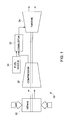
- FIG. 1 illustrates a schematic exemplary power generation system indicated by reference number 10.
- the power generation system 10 is a gas turbine system having a compressor 20, a combustor 22, and a turbine 24. Air enters the power generation system 10 though an air intake 30 which feeds into the compressor 20, and work is exerted on the air by the compressor 20. The compressed air is then mixed with fuel by a fuel nozzle 34. The fuel nozzle 34 injects an air-fuel mixture into the combustor 22 in a specific ratio for combustion. The heat release generates high temperature pressurized gas exhaust that drives blades (not shown) that are located within the turbine 24.
- the combustor 22 is a dry low NOx combustor.
- the combustor 22 includes an end cover 40 having a center nozzle gas fuel port 42 as well as a plurality of outer ports, or outer nozzle assemblies 44.
- the center nozzle gas fuel port 42 is located at a center axis A-A of the combustor 22, and the outer nozzle assemblies 44 surround the center nozzle gas fuel port 42.
- there are five outer nozzle assemblies 44 that surround the center nozzle gas fuel port 42 however it is to be understood that any number of outer nozzle assemblies 44 may be used.
- the center nozzle gas fuel port 42 and the outer nozzle assemblies 44 all selectively provide a gas fuel (not shown) to the combustor 22. However, only the outer nozzle assemblies 44 provide a liquid fuel (not shown) to the combustor 22. Specifically, only the outer nozzle assemblies 44 each include an outer nozzle gas fuel port 48 and a liquid cartridge or outer nozzle liquid fuel port 50. That is, the center nozzle gas fuel port 42 does not include a liquid cartridge. The center nozzle gas fuel port 42 and the outer nozzle gas fuel ports 48 provide the gas fuel, and the outer nozzle liquid fuel port 50 provides the liquid fuel.
- the power generation system 10 (shown in FIG. 1 ) operates on either the gas fuel or, alternatively, the liquid fuel.
- the flow of liquid fuel is stopped or ceased, and a purging flow such as, for example, a compressed air, is sent through the outer nozzle liquid fuel ports 50 of the outer nozzle assemblies 44.
- the purge flow is not activated until the flow of liquid fuel has ceased.
- the purge flow is a non-reactive medium such as, for example, nitrogen or water.
- the purge flow is compressed air.
- the purge flow may be a reactive medium natural gas. In the event natural gas is employed, first the liquid fuel is purged by water. The water is then purged by the natural gas.
- FIG. 2 is an illustration of the combustor 22 operating on the liquid fuel.
- the liquid fuel provided by the outer nozzle liquid fuel ports 50 is gradually decreased, while simultaneously starting and increasing the amount of gas fuel. That is, the liquid fuel is gradually decreased while still substantially maintaining the specified total energy to the power generation system 10 through the use of a gaseous fuel.
- FIG. 3 is an illustration of the combustor 22 operating on the gas fuel, where supply of the liquid fuel to the outer nozzle liquid fuel ports 50 of the outer nozzle assemblies 44 has ceased, but prior to the purging flow being supplied to the outer nozzle liquid fuel ports 50 of the outer nozzle assemblies 44. Instead, the gas fuel is supplied to the center nozzle gas fuel port 42 and the outer nozzle gas fuel ports 48 of the outer nozzle assemblies 44.
- Gas fuel is supplied to the center nozzle gas fuel port 42 and the gas nozzle 48 of the outer nozzle assemblies 44 at a specified fuel-air ratio such that the center nozzle flame (not shown) corresponding to the center nozzle gas fuel port 42 is anchored, and the gas nozzle flames (not shown) corresponding to the outer nozzle gas fuel ports 48 of the outer nozzle assemblies 44 are lifted.
- the specified fuel-air ratio generally exceeds a threshold value in order to create flame anchoring at either the center nozzle gas fuel port 42 or the outer nozzle gas ports 48 of the outer nozzle assemblies 44.
- the fuel-air ratio supplied to the center nozzle gas fuel port 42 exceeds the threshold value such that the center nozzle flame is anchored, and the fuel-air ratio supplied to the outer nozzle gas fuel port 48 of the outer nozzle assemblies 44 is less than the threshold value such that the gas nozzles flames are lifted.
- FIG. 4 is an illustration of the combustor 22 operating on the gas fuel, where the supply of the liquid fuel to the liquid injectors has ceased, and the purging flow is supplied to the outer nozzle liquid fuel ports 50.
- Gas fuel is supplied to the center nozzle gas fuel port 42 and the outer nozzle gas fuel port 48 of the outer nozzle assemblies 44 at the specified fuel-air ratio such that the center nozzle flame corresponding to the center nozzle gas fuel port 42 is still anchored.
- at least one of the the gas nozzle flames corresponding to one of the outer nozzle gas fuel ports 48 of the outer nozzle assemblies 44 are also anchored, and the remaining gas nozzle flames are lifted as the purge flow is supplied to the outer nozzle liquid fuel ports 50 of the outer nozzle assemblies 44.
- three gas nozzle flames are anchored. Specifically, the gas nozzle flames corresponding to the outer nozzle gas fuel ports 48 located at the one o'clock, the six o'clock, and the eleven o'clock position of the end cover 40 are anchored. The gas nozzle flames corresponding to the gas nozzles at the four o'clock and the eight o'clock position of the end cover 40 are lifted. It should be noted that the illustration of FIG. 4 is only one embodiment, and other approaches may be used as well.
- the outer nozzle gas fuel ports 48 at the one o'clock, the six o'clock, and the eleven o'clock position of the end cover 40 could be lifted, and the outer nozzle gas fuel ports 48 at the four o'clock and the eight o'clock position of the end cover 40 are anchored.
- FIG. 5 is a process flow diagram illustrating one approach of operating the power generation system 10 in the event that a transfer to from the liquid fuel to the gas fuel is required.
- process 200 begins at 202, where the liquid fuel is provided to only the outer nozzle liquid fuel ports 50 of the outer nozzle assemblies 44 at a specified total energy. Process 200 may then proceed to 204.
- the liquid fuel supplied to the outer nozzle liquid fuel ports 50 is gradually decreased, while simultaneously increasing the gas fuel to the center nozzle gas fuel port 42 and the outer nozzle gas fuel ports 48 of the outer nozzle assemblies 44 to generally maintain the specified total energy input to the gas turbine.
- Process 200 may then proceed to 206.
- the fuel-air ratio of the gas fuel supplied to the center nozzle gas fuel port 42 exceeds the threshold value such that the central nozzle flame is anchored.
- the specified fuel-air ratio generally has to exceed the threshold value in order to create flame anchoring at the center nozzle gas fuel port 42.
- Process 200 may then proceed to 208.
- the fuel-air ratio of the gas fuel supplied to the outer nozzle gas fuel ports 48 of the outer nozzle assemblies 44 is less than the threshold value such that the gas nozzles flames are lifted. Process 200 may then proceed to 210.
- Process 200 may then proceed to 212.
- the purge flow is supplied to the outer nozzle liquid fuel ports 50 of the outer nozzle assemblies 44.
- Process 200 may then proceed to 214.
- At least one of the gas nozzle flames corresponding to one of the outer nozzle gas fuel ports 48 of the outer nozzle assemblies 44 are anchored, and the remaining gas nozzle flames are lifted as the purge flow is supplied to the outer nozzle liquid fuel ports 50 of the outer nozzle assemblies 44.
- three gas nozzle flames are anchored. Process 200 may then terminate.
Landscapes
- Engineering & Computer Science (AREA)
- Chemical & Material Sciences (AREA)
- Combustion & Propulsion (AREA)
- Mechanical Engineering (AREA)
- General Engineering & Computer Science (AREA)
- Spray-Type Burners (AREA)
Abstract
Description
- The subject matter disclosed herein relates to a method of operating a combustor for a gas turbine from a liquid fuel operation to a gas fuel operation.
- Gas turbines include one or more combustors, which receive and combust air and fuel to produce hot combustion gases. For example, the gas turbine may include multiple combustion chambers positioned circumferentially around a rotational axis. Either a liquid fuel or a gas fuel may be injected into the combustor. In the event that the gas turbine is operating on liquid fuel and a transfer to gas fuel is required, the liquid fuel flow is first shut off or stopped, and then a purge fluid is sent through liquid fuel nozzles. The purging fluid removes any residual liquid fuel from the liquid fuel nozzles. There can be a delay between shutting of the liquid fuel flow and sending the purging air through the liquid fuel nozzles at a high enough flow rate or pressure. In the event a flame is anchored on the liquid fuel nozzles during the delay, a resulting pressure gradient may send hot combustion products into the liquid fuel nozzle, which in turn may cause damage.
- In some types of combustion systems such as, for example, dry low NOx combustion systems, the combustor may only transfer from liquid fuel operation to gas fuel operation at a relatively low load. The transfer between the liquid fuel and the gas fuel may be performed, but requires unloading the gas turbine to the reduced load first. In a combined cycle power plant, unloading the gas turbine to a low load may also require for a steam turbine to taken off-line as well.
- According to one aspect of the invention, a method of operating a combustor is provided. The combustor has a central nozzle and a plurality of outer nozzles surrounding the central nozzle. The method includes providing a liquid fuel to only the plurality of outer nozzles at a specified total energy input. The method includes decreasing the liquid fuel to the plurality of outer nozzles while simultaneously increasing a gas fuel to the central nozzle and the plurality of outer nozzles to substantially maintain the specified total energy input. The method includes ceasing the supply of the liquid fuel to the plurality of outer nozzles while substantially maintaining the specified total energy input. The method includes supplying a fuel-air ratio of the gas fuel to the central nozzle that exceeds a threshold value such that a central nozzle flame is anchored. The method includes supplying the fuel-air ratio of the gas fuel to the plurality of outer nozzles that is less than the threshold value such that pluralities of outer nozzle flames are lifted. The method includes supplying a purge flow to the plurality of outer nozzles.
- These and other advantages and features will become more apparent from the following description taken in conjunction with the drawings.
- The subject matter, which is regarded as the invention, is particularly pointed out and distinctly claimed in the claims at the conclusion of the specification. The foregoing and other features, and advantages of the invention are apparent from the following detailed description taken in conjunction with the accompanying drawings in which:
-
FIG. 1 is a schematic view of an exemplary gas turbine system having a combustor; -
FIG. 2 is an illustration of an end cover of the combustor shown inFIG. 1 during a mode of operation; -
FIG. 3 is an illustration of an end cover of the combustor shown inFIG. 1 during another mode of operation; -
FIG. 4 is an illustration of an end cover of the combustor shown inFIG. 1 during yet another mode of operation; and -
FIG. 5 is a process flow diagram illustrating one approach for operating the combustor shown inFIG. 1 . - The detailed description explains embodiments of the invention, together with advantages and features, by way of example with reference to the drawings.
-
FIG. 1 illustrates a schematic exemplary power generation system indicated byreference number 10. Thepower generation system 10 is a gas turbine system having acompressor 20, acombustor 22, and aturbine 24. Air enters thepower generation system 10 though anair intake 30 which feeds into thecompressor 20, and work is exerted on the air by thecompressor 20. The compressed air is then mixed with fuel by afuel nozzle 34. Thefuel nozzle 34 injects an air-fuel mixture into thecombustor 22 in a specific ratio for combustion. The heat release generates high temperature pressurized gas exhaust that drives blades (not shown) that are located within theturbine 24. In one embodiment, thecombustor 22 is a dry low NOx combustor. - Referring now to
FIGS. 2-4 , thecombustor 22 includes anend cover 40 having a center nozzlegas fuel port 42 as well as a plurality of outer ports, orouter nozzle assemblies 44. The center nozzlegas fuel port 42 is located at a center axis A-A of thecombustor 22, and theouter nozzle assemblies 44 surround the center nozzlegas fuel port 42. In the exemplary embodiment as shown inFIGS 2-4 , there are fiveouter nozzle assemblies 44 that surround the center nozzlegas fuel port 42, however it is to be understood that any number ofouter nozzle assemblies 44 may be used. - Referring to
FIGS. 2-4 , the center nozzlegas fuel port 42 and the outer nozzle assemblies 44 all selectively provide a gas fuel (not shown) to thecombustor 22. However, only theouter nozzle assemblies 44 provide a liquid fuel (not shown) to thecombustor 22. Specifically, only theouter nozzle assemblies 44 each include an outer nozzlegas fuel port 48 and a liquid cartridge or outer nozzleliquid fuel port 50. That is, the center nozzlegas fuel port 42 does not include a liquid cartridge. The center nozzlegas fuel port 42 and the outer nozzlegas fuel ports 48 provide the gas fuel, and the outer nozzleliquid fuel port 50 provides the liquid fuel. The power generation system 10 (shown inFIG. 1 ) operates on either the gas fuel or, alternatively, the liquid fuel. - In the event the
power generation system 10 is operating on liquid fuel and a transfer to the gas fuel is required, the flow of liquid fuel is stopped or ceased, and a purging flow such as, for example, a compressed air, is sent through the outer nozzleliquid fuel ports 50 of theouter nozzle assemblies 44. The purge flow is not activated until the flow of liquid fuel has ceased. In one embodiment, the purge flow is a non-reactive medium such as, for example, nitrogen or water. Alternatively, in another embodiment, the purge flow is compressed air. In yet another embodiment, the purge flow may be a reactive medium natural gas. In the event natural gas is employed, first the liquid fuel is purged by water. The water is then purged by the natural gas. -
FIG. 2 is an illustration of thecombustor 22 operating on the liquid fuel. As seen inFIG. 2 , only the outer nozzleliquid fuel ports 50 of theouter nozzle assemblies 44 provide the liquid fuel at a specified total energy to thepower generation system 10. In the event that a transfer to a gas fuel is needed, the liquid fuel provided by the outer nozzleliquid fuel ports 50 is gradually decreased, while simultaneously starting and increasing the amount of gas fuel. That is, the liquid fuel is gradually decreased while still substantially maintaining the specified total energy to thepower generation system 10 through the use of a gaseous fuel. -
FIG. 3 is an illustration of thecombustor 22 operating on the gas fuel, where supply of the liquid fuel to the outer nozzleliquid fuel ports 50 of theouter nozzle assemblies 44 has ceased, but prior to the purging flow being supplied to the outer nozzleliquid fuel ports 50 of theouter nozzle assemblies 44. Instead, the gas fuel is supplied to the center nozzlegas fuel port 42 and the outer nozzlegas fuel ports 48 of theouter nozzle assemblies 44. Gas fuel is supplied to the center nozzlegas fuel port 42 and thegas nozzle 48 of theouter nozzle assemblies 44 at a specified fuel-air ratio such that the center nozzle flame (not shown) corresponding to the center nozzlegas fuel port 42 is anchored, and the gas nozzle flames (not shown) corresponding to the outer nozzlegas fuel ports 48 of theouter nozzle assemblies 44 are lifted. The specified fuel-air ratio generally exceeds a threshold value in order to create flame anchoring at either the center nozzlegas fuel port 42 or the outernozzle gas ports 48 of theouter nozzle assemblies 44. Therefore, the fuel-air ratio supplied to the center nozzlegas fuel port 42 exceeds the threshold value such that the center nozzle flame is anchored, and the fuel-air ratio supplied to the outer nozzlegas fuel port 48 of theouter nozzle assemblies 44 is less than the threshold value such that the gas nozzles flames are lifted. -
FIG. 4 is an illustration of thecombustor 22 operating on the gas fuel, where the supply of the liquid fuel to the liquid injectors has ceased, and the purging flow is supplied to the outer nozzleliquid fuel ports 50. Gas fuel is supplied to the center nozzlegas fuel port 42 and the outer nozzlegas fuel port 48 of theouter nozzle assemblies 44 at the specified fuel-air ratio such that the center nozzle flame corresponding to the center nozzlegas fuel port 42 is still anchored. Also, at least one of the the gas nozzle flames corresponding to one of the outer nozzlegas fuel ports 48 of theouter nozzle assemblies 44 are also anchored, and the remaining gas nozzle flames are lifted as the purge flow is supplied to the outer nozzleliquid fuel ports 50 of theouter nozzle assemblies 44. In the exemplary embodiment as shown inFIG. 4 , three gas nozzle flames are anchored. Specifically, the gas nozzle flames corresponding to the outer nozzlegas fuel ports 48 located at the one o'clock, the six o'clock, and the eleven o'clock position of theend cover 40 are anchored. The gas nozzle flames corresponding to the gas nozzles at the four o'clock and the eight o'clock position of theend cover 40 are lifted. It should be noted that the illustration ofFIG. 4 is only one embodiment, and other approaches may be used as well. For example, in an alternative embodiment, the outer nozzlegas fuel ports 48 at the one o'clock, the six o'clock, and the eleven o'clock position of theend cover 40 could be lifted, and the outer nozzlegas fuel ports 48 at the four o'clock and the eight o'clock position of theend cover 40 are anchored. -
FIG. 5 is a process flow diagram illustrating one approach of operating thepower generation system 10 in the event that a transfer to from the liquid fuel to the gas fuel is required. Referring now to bothFIGS. 2 and5 ,process 200 begins at 202, where the liquid fuel is provided to only the outer nozzleliquid fuel ports 50 of theouter nozzle assemblies 44 at a specified total energy.Process 200 may then proceed to 204. - In 204, the liquid fuel supplied to the outer nozzle
liquid fuel ports 50 is gradually decreased, while simultaneously increasing the gas fuel to the center nozzlegas fuel port 42 and the outer nozzlegas fuel ports 48 of theouter nozzle assemblies 44 to generally maintain the specified total energy input to the gas turbine.Process 200 may then proceed to 206. - In 206, the fuel-air ratio of the gas fuel supplied to the center nozzle
gas fuel port 42 exceeds the threshold value such that the central nozzle flame is anchored. Specifically, the specified fuel-air ratio generally has to exceed the threshold value in order to create flame anchoring at the center nozzlegas fuel port 42.Process 200 may then proceed to 208. - In 208, the fuel-air ratio of the gas fuel supplied to the outer nozzle
gas fuel ports 48 of theouter nozzle assemblies 44 is less than the threshold value such that the gas nozzles flames are lifted.Process 200 may then proceed to 210. - In 210, the supply of the liquid fuel to the outer nozzle
liquid fuel ports 50 of theouter nozzle assemblies 44 is ceased, while generally maintaining the specified total energy input to the gas turbine.Process 200 may then proceed to 212. - In 212, the purge flow is supplied to the outer nozzle
liquid fuel ports 50 of theouter nozzle assemblies 44.Process 200 may then proceed to 214. - In 214, at least one of the gas nozzle flames corresponding to one of the outer nozzle
gas fuel ports 48 of theouter nozzle assemblies 44 are anchored, and the remaining gas nozzle flames are lifted as the purge flow is supplied to the outer nozzleliquid fuel ports 50 of theouter nozzle assemblies 44. For example, in the embodiment as shown inFIG. 4 , three gas nozzle flames are anchored.Process 200 may then terminate. - The approach of operating the
power generation system 10 in the event that a transfer to from the liquid fuel to the gas fuel is required as described inFIGS. 2-5 allows for a gas turbine to transfer from the liquid fuel to the gas fuel without the need to significantly reduce load. In a combined cycle power plant, maintaining the load during the transfer from the liquid fuel to the gas fuel also allows for a steam turbine to stay on-line as well. Thus, transferring from liquid fuel to gas fuel operation may be performed more frequently when employing thepower generation system 10. - While the invention has been described in detail in connection with only a limited number of embodiments, it should be readily understood that the invention is not limited to such disclosed embodiments. Rather, the invention can be modified to incorporate any number of variations, alterations, substitutions or equivalent arrangements not heretofore described, but which are commensurate with the spirit and scope of the invention. Additionally, while various embodiments of the invention have been described, it is to be understood that aspects of the invention may include only some of the described embodiments. Accordingly, the invention is not to be seen as limited by the foregoing description, but is only limited by the scope of the appended claims.
Claims (12)
- A method of operating a combustor (22), the combustor (22) having a central nozzle (42) and a plurality of outer nozzles (44) surrounding the central nozzle, comprising;
providing a liquid fuel to only the plurality of outer nozzles (44) at a specified total energy input;
decreasing the liquid fuel to the plurality of outer nozzles (44) while simultaneously increasing a gas fuel to the central nozzle (42) and the plurality of outer nozzles to substantially maintain the specified total energy input;
supplying a fuel-air ratio of the gas fuel to the central nozzle (42) that exceeds a threshold value such that a central nozzle flame is anchored;
supplying the fuel-air ratio of the gas fuel to the plurality of outer nozzles (44) that is less than the threshold value such that a plurality of outer nozzle flames are lifted;
ceasing a supply of the liquid fuel to the plurality of outer ports while substantially maintaining the specified total energy input; and
supplying a purge flow to the plurality of outer nozzles (44). - The method as recited in claim 1, comprising supplying the fuel-air ratio of the gas fuel to the plurality of outer nozzles (44) that exceeds the threshold value such that at least one of the plurality of outer nozzle flames are anchored as the purge flow is supplied to the plurality of outer nozzles.
- The method as recited in claim 2, comprising supplying the fuel-air ratio of the gas fuel that exceeds the threshold value to each of the plurality of outer nozzles (44) located at a one o'clock, a six o'clock, and an eleven o'clock position of an end cover.
- The method as recited in claim 1, 2 or 3, comprising providing a reactive medium as the purge flow.
- The method as recited in claim 4, comprising purging the liquid fuel by water before providing the reactive medium.
- The method as recited in any preceding claim, comprising providing one of a non-reactive medium that is at least one of nitrogen and water, or compressed air as the purge flow.
- The method as recited in any preceding claim, comprising including a gas fuel port (48) and a liquid fuel port (50) with each of the plurality of outer nozzles (44).
- The method as recited in claim 7, wherein the gas fuel port (48) provides the gas fuel and the liquid fuel port (50) provides the liquid fuel.
- The method as recited in any preceding claim 1, comprising locating the central nozzle (42) along a central axis of the combustor.
- The method as recited in any preceding claim, comprising providing five outer nozzles as the plurality of outer nozzles (44).
- The method as recited in any preceding claim, wherein the combustor (22) is a dry low NOx combustor.
- The method as recited in any preceding claim for operating a gas turbine (10) having a combustor, wherein the specified total energy input is a specified total energy input to the gas turbine (10).
Applications Claiming Priority (1)
| Application Number | Priority Date | Filing Date | Title |
|---|---|---|---|
| US13/412,110 US9003806B2 (en) | 2012-03-05 | 2012-03-05 | Method of operating a combustor from a liquid fuel to a gas fuel operation |
Publications (2)
| Publication Number | Publication Date |
|---|---|
| EP2636953A2 true EP2636953A2 (en) | 2013-09-11 |
| EP2636953A3 EP2636953A3 (en) | 2017-10-18 |
Family
ID=47844101
Family Applications (1)
| Application Number | Title | Priority Date | Filing Date |
|---|---|---|---|
| EP13157554.0A Withdrawn EP2636953A3 (en) | 2012-03-05 | 2013-03-04 | Method of operating a combustor from a liquid fuel to a gas fuel operation |
Country Status (5)
| Country | Link |
|---|---|
| US (1) | US9003806B2 (en) |
| EP (1) | EP2636953A3 (en) |
| JP (1) | JP6050148B2 (en) |
| CN (1) | CN103307632B (en) |
| RU (1) | RU2013109394A (en) |
Families Citing this family (3)
| Publication number | Priority date | Publication date | Assignee | Title |
|---|---|---|---|---|
| JP6177187B2 (en) * | 2014-04-30 | 2017-08-09 | 三菱日立パワーシステムズ株式会社 | Gas turbine combustor, gas turbine, control apparatus and control method |
| US20160341429A1 (en) * | 2015-05-20 | 2016-11-24 | General Electric Company | Gas turbine engine liquid fuel supply system and method |
| US11306661B1 (en) | 2020-12-04 | 2022-04-19 | General Electric Company | Methods and apparatus to operate a gas turbine engine with hydrogen gas |
Family Cites Families (20)
| Publication number | Priority date | Publication date | Assignee | Title |
|---|---|---|---|---|
| US4344280A (en) * | 1980-01-24 | 1982-08-17 | Hitachi, Ltd. | Combustor of gas turbine |
| US5359847B1 (en) * | 1993-06-01 | 1996-04-09 | Westinghouse Electric Corp | Dual fuel ultra-flow nox combustor |
| GB9321505D0 (en) * | 1993-10-19 | 1993-12-08 | Europ Gas Turbines Ltd | Fuel injector |
| US6269646B1 (en) * | 1998-01-28 | 2001-08-07 | General Electric Company | Combustors with improved dynamics |
| US6250063B1 (en) | 1999-08-19 | 2001-06-26 | General Electric Co. | Fuel staging apparatus and methods for gas turbine nozzles |
| US6598383B1 (en) | 1999-12-08 | 2003-07-29 | General Electric Co. | Fuel system configuration and method for staging fuel for gas turbines utilizing both gaseous and liquid fuels |
| US6427447B1 (en) | 2001-02-06 | 2002-08-06 | United Technologies Corporation | Bulkhead for dual fuel industrial and aeroengine gas turbines |
| JP4126974B2 (en) * | 2002-07-02 | 2008-07-30 | 株式会社Ihi | Fuel switching control device for gas turbine |
| US7104070B2 (en) * | 2004-03-04 | 2006-09-12 | General Electric Company | Liquid fuel nozzle apparatus with passive water injection purge |
| JP4775643B2 (en) * | 2006-06-06 | 2011-09-21 | 株式会社Ihi | Gas turbine fuel switching apparatus and method |
| US7770400B2 (en) * | 2006-12-26 | 2010-08-10 | General Electric Company | Non-linear fuel transfers for gas turbines |
| KR101024321B1 (en) * | 2008-10-31 | 2011-03-23 | 한국전력공사 | Gas turbine combustor for coal gas |
| JP4997217B2 (en) * | 2008-12-05 | 2012-08-08 | 株式会社日立製作所 | Gas turbine operating method and gas turbine combustor |
| EP2236793A1 (en) * | 2009-03-17 | 2010-10-06 | Siemens Aktiengesellschaft | Burner assembly |
| JP2011058775A (en) * | 2009-09-14 | 2011-03-24 | Hitachi Ltd | Gas turbine combustor |
| US20110091824A1 (en) * | 2009-10-20 | 2011-04-21 | Vinayak Barve | Method of operating a multi-fuel combustion system |
| US8919673B2 (en) * | 2010-04-14 | 2014-12-30 | General Electric Company | Apparatus and method for a fuel nozzle |
| JP5566777B2 (en) * | 2010-05-26 | 2014-08-06 | 三菱重工業株式会社 | Fuel switching control mechanism for dual fuel gas turbine plant, gas turbine plant, and fuel switching control method for dual fuel gas turbine plant |
| US9557050B2 (en) * | 2010-07-30 | 2017-01-31 | General Electric Company | Fuel nozzle and assembly and gas turbine comprising the same |
| US8613197B2 (en) * | 2010-08-05 | 2013-12-24 | General Electric Company | Turbine combustor with fuel nozzles having inner and outer fuel circuits |
-
2012
- 2012-03-05 US US13/412,110 patent/US9003806B2/en not_active Expired - Fee Related
-
2013
- 2013-03-01 JP JP2013040221A patent/JP6050148B2/en not_active Expired - Fee Related
- 2013-03-04 EP EP13157554.0A patent/EP2636953A3/en not_active Withdrawn
- 2013-03-04 RU RU2013109394/06A patent/RU2013109394A/en not_active Application Discontinuation
- 2013-03-05 CN CN201310069387.1A patent/CN103307632B/en not_active Expired - Fee Related
Non-Patent Citations (1)
| Title |
|---|
| None |
Also Published As
| Publication number | Publication date |
|---|---|
| RU2013109394A (en) | 2014-09-10 |
| US9003806B2 (en) | 2015-04-14 |
| JP6050148B2 (en) | 2016-12-21 |
| CN103307632B (en) | 2017-05-10 |
| US20130227956A1 (en) | 2013-09-05 |
| CN103307632A (en) | 2013-09-18 |
| EP2636953A3 (en) | 2017-10-18 |
| JP2013185585A (en) | 2013-09-19 |
Similar Documents
| Publication | Publication Date | Title |
|---|---|---|
| US8340886B2 (en) | System and method for transitioning between fuel supplies for a combustion system | |
| EP2592250B1 (en) | System for purging gas fuel circuit for a gas turbine engine | |
| JP4979615B2 (en) | Combustor and fuel supply method for combustor | |
| EP2415993B1 (en) | Advanced humid air turbines and fuel control method for advanced humid air turbines | |
| EP1182401B1 (en) | Method and apparatus for decreasing combustor emissions | |
| US9739488B2 (en) | Gas turbine combustor with two kinds of gas fuel supply systems | |
| JP4735548B2 (en) | High-humidity air-utilizing gas turbine and its operating method | |
| EP2738371A2 (en) | A system and method for operating a gas turbine in a turndown mode | |
| CN204026742U (en) | For supplying fuel to the system of burner | |
| JP6253066B2 (en) | Method of partial load CO reduction operation and gas turbine for a two-stage combustion gas turbine | |
| EP2532959B1 (en) | System and method for supplying fuel | |
| JP2015045331A (en) | System and method for controlling fuel distribution in a combustion chamber of a gas turbine engine | |
| JP6343504B2 (en) | 2-shaft gas turbine | |
| BR102013021469A2 (en) | method for mixing a dilution air into a gas turbine sequential combustion system | |
| JP2011141112A (en) | Apparatus and method for supplying fuel | |
| US9366189B2 (en) | System and method for reducing pressure oscillations within a gas turbine engine | |
| JP2014102066A (en) | Fuel supply system for supplying fuel to combustion section of gas turbine | |
| US10865991B2 (en) | Combustion apparatus and gas turbine including the same | |
| EP3391998B1 (en) | Turbomachine coupling assembly | |
| US9003806B2 (en) | Method of operating a combustor from a liquid fuel to a gas fuel operation | |
| JP6870970B2 (en) | Steam generation system by turbine extraction | |
| JP2007024357A (en) | Gas turbine combustor, method for preventing carbonization of fuel, and purge method | |
| US20170058769A1 (en) | SYSTEM AND METHOD FOR OPERATING A DRY LOW NOx COMBUSTOR IN A NON-PREMIX MODE | |
| US20200300181A1 (en) | Gas turbine and control method therefor | |
| US10584643B2 (en) | Method for operating a supply assembly for supplying fuel gas and inert media to a gas turbine combustor, such supply assembly and a gas turbine comprising such supply assembly |
Legal Events
| Date | Code | Title | Description |
|---|---|---|---|
| PUAI | Public reference made under article 153(3) epc to a published international application that has entered the european phase |
Free format text: ORIGINAL CODE: 0009012 |
|
| AK | Designated contracting states |
Kind code of ref document: A2 Designated state(s): AL AT BE BG CH CY CZ DE DK EE ES FI FR GB GR HR HU IE IS IT LI LT LU LV MC MK MT NL NO PL PT RO RS SE SI SK SM TR |
|
| AX | Request for extension of the european patent |
Extension state: BA ME |
|
| PUAL | Search report despatched |
Free format text: ORIGINAL CODE: 0009013 |
|
| AK | Designated contracting states |
Kind code of ref document: A3 Designated state(s): AL AT BE BG CH CY CZ DE DK EE ES FI FR GB GR HR HU IE IS IT LI LT LU LV MC MK MT NL NO PL PT RO RS SE SI SK SM TR |
|
| AX | Request for extension of the european patent |
Extension state: BA ME |
|
| RIC1 | Information provided on ipc code assigned before grant |
Ipc: F23R 3/36 20060101AFI20170913BHEP |
|
| 17P | Request for examination filed |
Effective date: 20180418 |
|
| RBV | Designated contracting states (corrected) |
Designated state(s): AL AT BE BG CH CY CZ DE DK EE ES FI FR GB GR HR HU IE IS IT LI LT LU LV MC MK MT NL NO PL PT RO RS SE SI SK SM TR |
|
| GRAP | Despatch of communication of intention to grant a patent |
Free format text: ORIGINAL CODE: EPIDOSNIGR1 |
|
| INTG | Intention to grant announced |
Effective date: 20180615 |
|
| STAA | Information on the status of an ep patent application or granted ep patent |
Free format text: STATUS: THE APPLICATION IS DEEMED TO BE WITHDRAWN |
|
| 18D | Application deemed to be withdrawn |
Effective date: 20181026 |