EP2636878A1 - Noise-reducing engine nozzle system - Google Patents
Noise-reducing engine nozzle system Download PDFInfo
- Publication number
- EP2636878A1 EP2636878A1 EP13158670.3A EP13158670A EP2636878A1 EP 2636878 A1 EP2636878 A1 EP 2636878A1 EP 13158670 A EP13158670 A EP 13158670A EP 2636878 A1 EP2636878 A1 EP 2636878A1
- Authority
- EP
- European Patent Office
- Prior art keywords
- nozzle
- aft portion
- section
- curve
- engine
- Prior art date
- Legal status (The legal status is an assumption and is not a legal conclusion. Google has not performed a legal analysis and makes no representation as to the accuracy of the status listed.)
- Granted
Links
- 238000000034 method Methods 0.000 claims abstract description 16
- 239000007789 gas Substances 0.000 claims description 6
- 239000003570 air Substances 0.000 description 6
- 230000008569 process Effects 0.000 description 6
- 238000011144 upstream manufacturing Methods 0.000 description 6
- 238000010586 diagram Methods 0.000 description 4
- 230000007246 mechanism Effects 0.000 description 4
- 230000008859 change Effects 0.000 description 3
- 239000010432 diamond Substances 0.000 description 3
- 230000035939 shock Effects 0.000 description 3
- 239000003381 stabilizer Substances 0.000 description 3
- 230000004048 modification Effects 0.000 description 2
- 238000012986 modification Methods 0.000 description 2
- 230000003068 static effect Effects 0.000 description 2
- 239000012080 ambient air Substances 0.000 description 1
- 230000001174 ascending effect Effects 0.000 description 1
- 230000015572 biosynthetic process Effects 0.000 description 1
- 230000006835 compression Effects 0.000 description 1
- 238000007906 compression Methods 0.000 description 1
- 239000000203 mixture Substances 0.000 description 1
- 238000010248 power generation Methods 0.000 description 1
Images










Classifications
-
- B—PERFORMING OPERATIONS; TRANSPORTING
- B64—AIRCRAFT; AVIATION; COSMONAUTICS
- B64D—EQUIPMENT FOR FITTING IN OR TO AIRCRAFT; FLIGHT SUITS; PARACHUTES; ARRANGEMENT OR MOUNTING OF POWER PLANTS OR PROPULSION TRANSMISSIONS IN AIRCRAFT
- B64D33/00—Arrangement in aircraft of power plant parts or auxiliaries not otherwise provided for
- B64D33/04—Arrangement in aircraft of power plant parts or auxiliaries not otherwise provided for of exhaust outlets or jet pipes
- B64D33/06—Silencing exhaust or propulsion jets
-
- F—MECHANICAL ENGINEERING; LIGHTING; HEATING; WEAPONS; BLASTING
- F02—COMBUSTION ENGINES; HOT-GAS OR COMBUSTION-PRODUCT ENGINE PLANTS
- F02K—JET-PROPULSION PLANTS
- F02K1/00—Plants characterised by the form or arrangement of the jet pipe or nozzle; Jet pipes or nozzles peculiar thereto
- F02K1/04—Mounting of an exhaust cone in the jet pipe
-
- F—MECHANICAL ENGINEERING; LIGHTING; HEATING; WEAPONS; BLASTING
- F02—COMBUSTION ENGINES; HOT-GAS OR COMBUSTION-PRODUCT ENGINE PLANTS
- F02K—JET-PROPULSION PLANTS
- F02K1/00—Plants characterised by the form or arrangement of the jet pipe or nozzle; Jet pipes or nozzles peculiar thereto
- F02K1/38—Introducing air inside the jet
- F02K1/386—Introducing air inside the jet mixing devices in the jet pipe, e.g. for mixing primary and secondary flow
-
- F—MECHANICAL ENGINEERING; LIGHTING; HEATING; WEAPONS; BLASTING
- F02—COMBUSTION ENGINES; HOT-GAS OR COMBUSTION-PRODUCT ENGINE PLANTS
- F02K—JET-PROPULSION PLANTS
- F02K1/00—Plants characterised by the form or arrangement of the jet pipe or nozzle; Jet pipes or nozzles peculiar thereto
- F02K1/46—Nozzles having means for adding air to the jet or for augmenting the mixing region between the jet and the ambient air, e.g. for silencing
-
- F—MECHANICAL ENGINEERING; LIGHTING; HEATING; WEAPONS; BLASTING
- F02—COMBUSTION ENGINES; HOT-GAS OR COMBUSTION-PRODUCT ENGINE PLANTS
- F02K—JET-PROPULSION PLANTS
- F02K1/00—Plants characterised by the form or arrangement of the jet pipe or nozzle; Jet pipes or nozzles peculiar thereto
- F02K1/46—Nozzles having means for adding air to the jet or for augmenting the mixing region between the jet and the ambient air, e.g. for silencing
- F02K1/48—Corrugated nozzles
Definitions
- the present disclosure relates generally to engines and, in particular, to a method and apparatus for reducing noise generated during operation of an engine. Still more particularly, the present disclosure relates to a method and apparatus for reducing noise generated by the exhaust jet of an engine.
- An aircraft may generate different types of noise during different phases of flight. These different phases of flight may include taxiing, takeoff, landing, cruising, ascending, descending, and/or other phases of flight. In some cases, the noise generated by an aircraft may be undesirable to the passengers and/or crew onboard the aircraft. For example, noise generated during a cruise phase of flight may be undesirable to the passengers and/or crew of an aircraft.
- One source of the noise generated during operation of an aircraft may be the operation of an engine of the aircraft.
- the flow of exhaust exiting an engine of an aircraft during operation of the engine may contribute to the undesirable noise produced during operation of an aircraft.
- the flow of exhaust exiting an engine is referred to as an exhaust jet.
- the exhaust jet is a stream of exhaust gases that flow out of the engine through a nozzle system for the engine. This stream of gases is used to move the aircraft.
- the pattern with which the exhaust jet flows out of the nozzle system may be referred to as an exhaust plume.
- shock-cell pattern may form in the exhaust jet.
- This shock-cell pattern may be one factor that contributes to the noise generated during operation of an engine of an aircraft.
- the noise associated with this shock-cell pattern is referred to as shock-associated broadband noise or shock-cell noise.
- a number of different mechanisms have been used to reduce the amount of noise generated during operation of an engine. These mechanisms include adding chevrons and/or serrations to one or more nozzles in the nozzle system for the engine.
- these currently available mechanisms for reducing the noise generated by an engine may not reduce the noise to within selected tolerances.
- currently available mechanisms may not reduce the shock-cell noise generated by an engine during a cruise phase of flight to within selected tolerances.
- a nozzle system comprises a first nozzle and a second nozzle at least partially surrounded by the first nozzle.
- An outer surface of an aft portion of the second nozzle has a shape configured such that a radial cross-section of the outer surface of the aft portion of the second nozzle has a curve that is different from at least one other curve for another radial cross-section of the outer surface of the aft portion of the second nozzle and such that an axial cross-section of the outer surface of the aft portion of the second nozzle has a wavy shape.
- an engine comprises a housing and a nozzle system at an aft end of the housing for the engine.
- the nozzle system comprises a fan nozzle and a core nozzle.
- the core nozzle is at least partially surrounded by the fan nozzle.
- An outer surface of an aft portion of the core nozzle has a shape that is selected to reduce noise generated during operation of the engine.
- the shape of the outer surface of the aft portion of the core nozzle is configured such that a radial cross-section of the outer surface of the aft portion of the core nozzle has a curve that is different from at least one other curve for another radial cross-section of the outer surface of the aft portion of the core nozzle and such that an axial cross-section of the outer surface of the aft portion of the second nozzle has a wavy shape.
- a method for reducing noise generated by an engine is provided.
- the engine is operated.
- the engine has a nozzle system comprising a first nozzle and a second nozzle.
- the second nozzle is at least partially surrounded by the first nozzle.
- An outer surface of an aft portion of the second nozzle has a shape configured such that a radial cross-section of the outer surface of the aft portion of the second nozzle has a curve that is different from at least one other curve for another radial cross-section of the outer surface of the aft portion of the second nozzle.
- the noise generated during operation of the engine is reduced using the second nozzle of the nozzle system and such that an axial cross-section of the outer surface of the aft portion of the second nozzle has a wavy shape.
- the different illustrative embodiments recognize and take into account different considerations. For example, the different illustrative embodiments recognize and take into account that noise, including shock-cell noise, produced by an engine during operation of an aircraft may be undesirable. The noise produced by an engine of an aircraft may be undesirable to the passengers and/or crew onboard the aircraft while the aircraft is in flight.
- the different illustrative embodiments recognize and take into account that it may be desirable to have a nozzle system that is configured to reduce noise, and in particular, shock-cell noise, to within selected tolerances.
- the different illustrative embodiments provide a method and apparatus for reducing noise generated during operation of a propulsion system.
- nozzle system 100 is part of engine 102.
- Engine 102 may be configured for use in platform 104.
- platform 104 is aerospace vehicle 105.
- Aerospace vehicle 105 may be selected from one of an aircraft, a jet aircraft, a missile, a spacecraft, a space shuttle, or some other suitable type of vehicle configured for travel in air and/or space.
- platform 104 may be some other suitable type of mobile platform configured to move using engine 102.
- engine 102 may be configured for use in a stationary platform. For example, engine 102 may be used in a power generation system.
- engine 102 may take the form of propulsion system 103 when platform 104 is aerospace vehicle 105.
- a "propulsion system” is any system configured to produce thrust to push an object forward.
- engine 102 may be a jet engine. More specifically, engine 102 may be a turbofan engine. Of course, in other illustrative examples, engine 102 may be a turbojet engine, a rocket engine, or some other suitable type of propulsion system for aerospace vehicle 105.
- Propulsion system 103 is configured to generate and expel exhaust 106 through nozzle system 100 to generate the thrust needed to move platform 104.
- the flow of exhaust 106 exiting nozzle system 100 is exhaust jet 107 in these illustrative examples.
- the shape and/or pattern of exhaust jet 107 exiting nozzle system 100 may be referred to as the exhaust plume for propulsion system 103.
- exhaust jet 107 comprises first jet stream 108 and second jet stream 110 that exit propulsion system 103 through nozzle system 100 at substantially the same time.
- First jet stream 108 is a first flow of exhaust 106 that exits propulsion system 103 through first nozzle 112 of nozzle system 100.
- Second jet stream 110 is a second flow of exhaust 106 that exits propulsion system 103 through second nozzle 114 of nozzle system 100.
- first nozzle 112 may be fan nozzle 116.
- second nozzle 114 may be core nozzle 118 in these examples.
- second nozzle 114 may be referred to as a primary nozzle, while first nozzle 112 may be referred to as a secondary nozzle.
- first nozzle 112 may be fan nozzle 116, while second nozzle 114 may be a vent nozzle associated with a core nozzle. This vent nozzle may be referred to as a tertiary nozzle or a tertiary vent nozzle.
- First nozzle 112 at least partially surrounds second nozzle 114.
- second nozzle 114 may be located within first nozzle 112.
- second nozzle 114 is nested within first nozzle 112.
- first nozzle 112 and second nozzle 114 may be substantially concentric to each other.
- center axis 113 may be a center axis for both first nozzle 112 and second nozzle 114.
- center axis 113 may only be a center axis for second nozzle 114, and first nozzle 112 may have a different center axis substantially parallel to but offset from center axis 113.
- first nozzle 112 may extend downstream of second nozzle 114 or second nozzle 114 may extend downstream of first nozzle 112.
- downstream is towards an aft end of aerospace vehicle 105.
- upstream is towards a forward end of aerospace vehicle 105.
- nozzle system 100 may include plug 115 in addition to first nozzle 112 and second nozzle 114.
- plug 115 is nested within second nozzle 114.
- plug 115 may share center axis 113 with first nozzle 112 2 and second nozzle 114.
- plug 115 may have a different center axis that is substantially parallel to but offset from center axis 113.
- plug 115 may have channel 117.
- Channel 117 may be present in plug 115 to vent gases generated by propulsion system 103. This flow of gases exiting channel 117 in plug 115 is vent stream 119.
- second jet stream 110 is surrounded by first jet stream 108 as these two jet streams exit nozzle system 100.
- Inner shear layer 121 is formed at the interface between first jet stream 108 and second jet stream 110.
- Outer shear layer 122 is formed at the interface between first jet stream 108 and the air around exhaust jet 107. In some cases, outer shear layer 122 may be at least partially formed by a mixture of first jet stream 108 and second jet stream 110, as well as the air around exhaust jet 107.
- additional shear layer 124 is formed between first jet stream 108 and vent stream 119.
- first jet stream 108 and/or second jet stream 110 may exit nozzle system 100 at speeds greater than the speed of sound.
- shock-cell pattern 120 may form within first jet stream 108 and/or second jet stream 110.
- Shock-cell pattern 120 comprises shock-cells, also referred to as shock diamonds or shock-cell diamonds, within exhaust jet 107 that may be visible.
- shock-cells or shock-cell diamonds are a formation of stationary wave patterns that appear in a jet stream.
- Shock-cell pattern 120 is formed when a jet stream that exits nozzle system 100 is supersonic and is either over-expanded or under-expanded.
- the jet stream is over-expanded when the static pressure of the jet stream exiting a nozzle is less than the static pressure of the flow of air and/or exhaust surrounding that jet stream.
- the jet stream is under-expanded when the pressure of the jet stream exiting the nozzle is greater than the pressure of the flow of air and/or exhaust surrounding that jet stream.
- a jet stream may be under-expanded at cruise conditions at high altitudes.
- shock-cell noise 128 When shock-cell pattern 120 is formed within first jet stream 108 and/or second jet stream 110, noise 126 generated during operation of propulsion system 120 includes shock-cell noise 128.
- Noise 126 is the noise associated with the flow of exhaust 106 from nozzle system 100. In other words, noise 126 is the noise associated with exhaust jet 107 exiting nozzle system 100.
- shock-cell noise 128 also may be referred to as shock-associated broadband noise.
- Nozzle system 100 is configured to reduce noise 126, and in particular, shock-cell noise 128, to within selected tolerances.
- second nozzle 114 of nozzle system 100 is configured to reduce shock-cell noise 128 generated during a cruise phase of flight for aerospace vehicle 105 to within selected tolerances.
- nozzle system 100 may be configured to reduce shock-cell noise 128 generated during other phases of flight.
- second nozzle 114 has inner surface 130 and outer surface 132. Further, in these illustrative examples, second nozzle 114 includes plurality of extensions 143 configured to extend aftwards from exit boundary 140 along outer surface 132. Each extension in plurality of extensions 143 may have a base that lies along exit boundary 140 of outer surface 132 and a tip located downstream of exit boundary 140.
- Plurality of extensions 143 may be referred to as, for example, without limitation, serrations or chevrons. Depending on the implementation, these extensions may have a trapezoidal shape, a triangular shape, or some other suitable type of shape. Plurality of extensions 143 may be configured to reduce noise 126.
- plurality of extensions 143 may be part of aft portion 135 of second nozzle 114.
- Aft portion 135 of second nozzle 114 is the portion of second nozzle 114 between selected axial plane 138 through second nozzle 114 and aftmost axial plane 136 through second nozzle 114.
- an "axial plane" through second nozzle 114 such as aftmost axial plane 136 or selected axial plane 138, is a plane through second nozzle 114 that is substantially perpendicular to center axis 113 through second nozzle 114.
- Selected axial plane 138 may be any axial plane through second nozzle 114 that is located upstream of plurality of extensions 143. In other words, none of the extensions in plurality of extensions 143 may have a portion located upstream of selected axial plane 138.
- exit boundary 140 from which plurality of extensions 143 extend may be contained within a single axial plane through second nozzle 114. In other illustrative examples, exit boundary 140 may span more than one axial plane through second nozzle 114.
- Aftmost axial plane 136 is the axial plane through second nozzle 114 located at the aftmost portion of trailing edge 142 of second nozzle 114. Trailing edge 142 is the aft edge where second nozzle 114 ends. At least a portion of trailing edge 142 is formed by the aft edges of the extensions in plurality of extensions 143. Aftmost axial plane 136 may be the axial plane through the aftmost tip of the tips of plurality of extensions 143.
- outer surface 132 of aft portion 135 of second nozzle 114 has shape 133 configured to reduce shock-cell noise 128.
- shape 133 of the portion of outer surface 132 between selected axial plane 138 and aftmost axial plane 136 is configured such that a radial cross-section of this portion of outer surface 132 through second nozzle 114 is curved.
- radial cross-section through second nozzle 114 is a cross-section through a radial plane through second nozzle 114.
- a "radial plane” through second nozzle 114 is any plane through second nozzle 114 that includes center axis 113.
- a radial plane is a plane in which center axis 113 lies.
- shape 133 is configured such that a radial cross-section of the portion of outer surface 132 between selected axial plane 138 and aftmost axial plane 136 has a curve that is different from at least one other curve for another radial cross-section of the portion of outer surface 132 between selected axial plane 138 and aftmost axial plane 136.
- shape 133 of the portion of outer surface 132 within aft portion 135 of second nozzle 114 is configured such that different radial cross-sections of this portion of outer surface 132 may have different curves. Further, in these illustrative examples, any radial cross-section of the portion of outer surface 132 located upstream of selected axial plane 138 of second nozzle 114 may not be curved. Instead, this radial cross-section may be substantially linear.
- An "axial cross-section" through second nozzle 114 is a cross-section through an axial plane through second nozzle 114.
- second nozzle 114 has plurality of extensions 143, axial cross-sections of outer surface 132 of second nozzle 114 at and upstream of exit boundary 140 are continuous. Further, axial cross-sections of outer surface 132 of second nozzle 114 downstream of exit boundary 140 may be discontinuous.
- shape 133 of the portion of outer surface 132 of second nozzle 114 between selected axial plane 138 and trailing edge 142 causes different axial cross-sections of outer surface 132 through aft portion 135 of second nozzle 114 to be non-circular, and in some cases, non-symmetrical.
- an axial cross-section of outer surface 132 along an axial plane between selected axial plane 138 and trailing edge 142 may be non-axisymmetrical.
- Shape 133 is configured such that the axial cross-section of outer surface 132 along an axial plane between selected axial plane 138 and aftmost axial plane 136 has a wavy shape.
- the axial cross-section of outer surface 132 between selected axial plane 138 and aftmost axial plane 136 may be a wavy shape comprising at least one of hills and valleys with respect to center axis 113 through second nozzle 114.
- the axial cross-section of outer surface 132 may have a wavy shape that comprises hills, valleys, or a combination of the two when viewed from center axis 113.
- the wavy shape may be discontinuous. Depending on the implementation, only hills or only valleys may be seen with this type of axial cross-section.
- Curve 144 is an example of a curve for a radial cross-section of outer surface 132 of aft portion 135 of second nozzle 114.
- curve 144 is for the radial cross-section of outer surface 132 of aft portion 135 of second nozzle 114 along radial plane 146.
- Curve 144 begins at selected axial plane 138 and ends at trailing edge 142.
- Curve 144 may have number of portions 148 with number of curvatures 150.
- a "number of" items means one or more items.
- number of portions 148 means one or more portions.
- Each portion in number of portions 148 has a corresponding curvature in number of curvatures 150.
- a "curvature" of a curve, such as curve 144, at any point, P, along curve 144 is defined as the reciprocal of the radius of the circle that most closely approximates curve 144 at or near that point, P.
- This circle may be referred to as an "osculating circle.”
- the curvature of this point, P is the rate of change of the angle of the tangent at the point, P, on curve 144 per unit length of curve 144.
- the curvature at this point, P may be referred to as being "convex,” with respect to the flow over outer surface 132.
- the curvature at this point, P may be referred to as being "concave,” with respect to the flow over outer surface 132.
- the different curvatures along curve 144 may be concave curvatures, convex curvatures, or some combination of the two.
- the curvature at all points along curve 144 may be the same. In another illustrative example, the curvature at different points along curve 144 may be different. In some cases, the curvature along curve 144 may continuously change between selected axial plane 138 and trailing edge 142. In this manner, shape 133 for outer surface 132 of aft portion 135 of second nozzle 114 may take a number of different forms, depending on the implementation.
- shape 133 formed by the different curvatures selected for the different curves for outer surface 132 of aft portion 135 of second nozzle 114 are selected to reduce shock-cell noise 128 to within selected tolerances.
- shape 133 may be selected to reduce shock-cell noise 128 associated with shock-cell pattern 120 in first jet stream 108 and/or second jet stream 110 to within selected tolerances during a cruise phase of flight and/or other phases of flight for aerospace vehicle 105.
- an outer surface of an aft portion of first nozzle 112 may have a shape configured similar to shape 133 of outer surface 132 of aft portion 135 of second nozzle 114. This shape may be configured to reduce shock-cell noise 128 if shock-cells are formed in the air around first jet stream 108 when aerospace vehicle 105 is travelling at supersonic speeds.
- first nozzle 112 may have a plurality of extensions.
- the shape of the outer surface of an aft portion of first nozzle 112 may be configured such that a particular curve for a radial cross-section of the outer surface of first nozzle 112 through first nozzle 112 is different from a curve for at least one other radial cross-section of the outer surface of first nozzle 112.
- an outer surface of an aft portion of plug 115 may have a shape similar to shape 133 of outer surface 132 of aft portion 135 of second nozzle 114. This shape may be configured to reduce shock-cell noise 128 associated with second jet stream 110.
- plug 115 may have a plurality of extensions.
- the shape of the outer surface of an aft portion of plug 115 may be configured such that a particular curve for a radial cross-section of the outer surface of plug 115 through plug 115 is different from a curve for at least one other radial cross-section of the outer surface of plug 115.
- the shapes of the outer surfaces of the different nozzles in nozzle system 100 may be configured in a number of different ways to reduce shock-cell noise 128 to within selected tolerances.
- the outer surface of the aft portion of at least one of first nozzle 112, second nozzle 114, and plug 115 may have a shape configured to reduce shock-cell noise 128.
- nozzle system 100 in Figure 1 is not meant to imply physical or architectural limitations to the manner in which an illustrative embodiment may be implemented.
- Other components in addition to and/or in place of the ones illustrated may be used. Some components may be unnecessary.
- the blocks are presented to illustrate some functional components. One or more of these blocks may be combined, divided, or combined and divided into different blocks when implemented in an illustrative embodiment.
- nozzle system 100 may not include plug 115.
- second nozzle 114 may not have plurality of extensions 143.
- the different extensions in plurality of extensions 143 may have different lengths taken from the base to the tip of an extension.
- a third nozzle may be associated with second nozzle 114.
- This third nozzle may be a vent nozzle associated with outer surface 132 of second nozzle 114.
- an outer surface of an aft portion of this third nozzle may have a shape configured similar to shape 133 for outer surface 132 of aft portion 135 of second nozzle 115.
- the shape of the outer surface of the aft portion of this third nozzle may be configured to help reduce shock-cell noise 128.
- different curves for outer surface 132 of aft portion 135 of second nozzle 114 along different radial planes through second nozzle 114 may begin at different selected axial planes through second nozzle.
- one curve may begin at selected axial plane 138 and another curve may begin at an axial plane located downstream of selected axial plane 138.
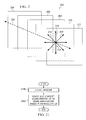
- center axis 200 is an example of center axis 113 in Figure 1 .
- center axis 200 may be a center axis for nozzle system 100 in Figure 1 .
- first nozzle 112, second nozzle 114, and plug 115 in Figure 1 may be substantially concentric to each other with respect to center axis 113.
- Axial planes 202 are planes perpendicular to center axis 200.
- Axial planes 202 include axial plane 204, axial plane 206, axial plane 208, axial plane 210, and axial plane 211.
- Axial plane 204 may be an example of selected axial plane 138 in Figure 1 .
- Axial plane 211 may be an example of aftmost axial plane 136 in Figure 1 .
- exit boundary 140 in Figure 1 may be contained within axial plane 210.
- Axial cross-sections of outer surface 132 of aft portion 135 of second nozzle 114 in Figure 1 taken along axial planes 202 may appear non-circular and non-symmetrical when outer surface 132 of aft portion 135 of second nozzle 114 has shape 133 in Figure 1 .
- axial cross-sections of outer surface 132 of second nozzle 114 in Figure 1 taken along any axial planes through second nozzle 114 upstream of axial plane 204 may appear substantially circular and symmetrical.
- radial axes 212 are axes that intersect center axis 200.
- Radial axes 212 include radial axis 214, radial axis 216, and radial axis 218.
- the plane formed by one of these radial axis and center axis 200 is referred to as a radial plane.
- the plane formed by radial axis 214 and center axis 200 is an example of one implementation for radial plane 146 in Figure 1 .
- the radial cross-sections of outer surface 132 of aft portion 135 may have different curves.
- the radial cross-section of outer surface 132 of aft portion 135 of second nozzle 114 taken along the radial plane formed by radial axis 214 and center axis 200 may have a curve that is different from the curve for the radial cross-section of outer surface 132 of aft portion 135 of second nozzle 114 along the radial plane formed by radial axis 216 and center axis 200.
- axial planes 202 and the radial planes formed by radial axes 212 and center axis 200 may be for first nozzle 112 in Figure 1 .
- axial planes 202 and the radial planes formed by radial axes 212 and center axis 200 may be for a plug, such as plug 115 in Figure 1 , instead of a nozzle.
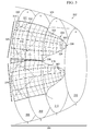
- aft portion 300 of core nozzle 302 is a representation of one example of an implementation for aft portion 135 of core nozzle 118 in Figure 1 .
- core nozzle 302 has plurality of extensions 304.
- Plurality of extensions 304 includes extension 305 and extension 307.
- Axial plane 306, axial plane 308, axial plane 310, and axial plane 312 are axial planes through aft portion 300 of nozzle 302.
- Axial plane 306 is an example of selected axial plane 138 in Figure 1 .
- Axial plane 312 is an example of aftmost axial plane 138 in Figure 1 .
- Aft portion 300 of core nozzle 302 is the portion of core nozzle 302 between axial plane 306 and axial plane 312.
- outer surface 314 of aft portion 300 of core nozzle 302 has shape 315.
- Shape 315 is configured such that different radial cross-sections of outer surface 314 have different curves.
- shape 315 is configured such that portion 326 of outer surface 314 has substantially the same shape as portion 328 of outer surface 314.
- Curves 316 are examples of curves for outer surface 314 of aft portion 300 of core nozzle 302 along different radial planes through core nozzle 302. As depicted in this example, all of curves 316 for outer surface 314 begin at axial plane 306 and end at trailing edge 318 of core nozzle 302.
- Curve 320, curve 322, and curve 324 are examples of curves 316. These three curves lie along different radial planes through core nozzle 302.
- the different curvatures along the different curves for the portion of outer surface 314 at and near tip 334 of extension 305 are selected such that an axial cross-section of this portion of outer surface 314 at and near tip 334 of extension 336 appears as a hill.
- the different curvatures along the different curves for the portion of outer surface 314 at and near interface 336 between extension 305 and extension 307 are selected such that an axial cross-section of this portion of outer surface 314 at and near interface appears 336 as a valley.
- shape 315 is configured such that the curvature along a curve in curves 316 is different from the curvature along other curves in curves 316 beginning at axial plane 306.
- outer surface 314 of aft portion 300 of core nozzle 314 may have a shape configured such that all curves along all radial planes through core nozzle 302 have the same selected curvature between axial plane 306 and boundary 330.
- outer surface 314 of aft portion 300 may have a shape configured such that the curvatures along curve 320, curve 322, and curve 324 are the same up until boundary 330 and different downstream of boundary 330 up until trailing edge 318.
- outer surface 314 of aft portion 300 of core nozzle 314 may have a shape configured such that all curves along all radial planes through core nozzle 302 have the same selected curvature between axial plane 306 and boundary 332.
- outer surface 314 of aft portion 300 may have a shape configured such that the curvatures along curve 320, curve 322, and curve 324 are the same up until boundary 332 and different downstream of boundary 330 up until trailing edge 318.
- Engine 400 in Figures 4-20 may be implemented in an aerospace vehicle, such as aerospace vehicle 105 in Figure 1 .
- Engine 400 may be an example of engine 102 in Figure 1 .
- engine 400 may be implemented in a jet aircraft.
- engine 400 is a turbofan engine.
- the different configurations for nozzle system 400 for engine 400 are selected to reduce noise generated by engine 400 during operation of engine 400. More specifically, these different configurations for nozzle system 403 are selected to reduce shock-cell noise.
- engine 400 includes nacelle 402 and nozzle system 403.
- Nacelle 402 is a housing for engine 400.
- Nozzle system 403 is an example of one implementation for nozzle system 100 in Figure 1 .
- Nozzle system 403 is located at an aft end of nacelle 402.
- Nozzle system 403 includes fan nozzle 404, core nozzle 406, and plug 408.
- Fan nozzle 404 is an example of one implementation for fan nozzle 112 in Figure 1 .
- Core nozzle 406 is an example of one implementation for core nozzle 114 in Figure 1 .
- plug 408 is an example of one implementation for plug 115 in Figure 1 . As depicted, plug 408 has a conical shape in this example.
- Fan nozzle 404 and core nozzle 406 allow exhaust generated during operation of engine 400 to exit engine 400 in the form an exhaust jet.
- core nozzle 406 is nested within fan nozzle 404.
- Plug 408 is nested within core nozzle 406.
- plug 408, core nozzle 406, and fan nozzle 404 share center axis 410.
- the center axis for plug 408, core nozzle 406, and fan nozzle 404 may be substantially parallel but offset from each other.
- Fan nozzle 404 has trailing edge 412. Further, core nozzle 406 has trailing edge 414 formed by plurality of extensions 416.
- Plurality of extensions 416 are an example of one implementation for plurality of extensions 53 in Figure 1 .
- Plurality of extensions 416 may also be referred to as a plurality of chevrons or a plurality of serrations in some cases.
- Core nozzle 406 has outer surface 418.
- the shape of outer surface 418 of aft portion 420 of core nozzle 406 is configured such that outer surface 418 of aft portion 420 is curved.
- the shape of outer surface 418 is described in greater detail in the figures below.
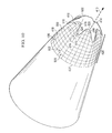
- FIG. 5 an illustration of a perspective view of core nozzle 406 of nozzle system 403 is depicted in accordance with an illustrative embodiment.
- An enlarged view of core nozzle 406 from Figure 4 is depicted in Figure 5 .
- azimuthal lines 500 and longitudinal lines 502 on outer surface 418 of core nozzle 406 are contour lines that indicate the shape of outer surface 418 of aft portion 420 of core nozzle 406.
- Azimuthal lines 500 lie along axial planes through core nozzle 406.
- Longitudinal lines 502 lie along radial planes through core nozzle 406.
- outer surface 418 of aft portion 420 of core nozzle 406 is curved.
- outer surface 418 has plurality of curves 504 that lie along a plurality of radial planes through center axis 410.
- outer surface 418 formed by plurality of curves 504 is indicated by longitudinal lines 502 depicted on outer surface 418.
- longitudinal line 506 indicates the shape of curve 510 of outer surface 418 beginning at selected axial plane 508 and ending at trailing edge 414.
- Selected axial plane 508 coincides with azimuthal line 507 in this example.
- all of the curves in plurality of curves 504 begin at selected axial plane 508 and end at trailing edge 414 of core nozzle 406.
- the curvature along each curve in plurality of curves 504 change along the direction of center axis 410.
- the curvature along curve 510 may be greater closer to trailing edge 418 as compared to the curvature of curve 510 closer to selected axial plane 508.
- the curvature of curve 510 near trailing edge 418 may be greater than the curvature of curve 512 indicated by longitudinal line 514 near trailing edge 418.
- plurality of extensions 416 includes extension 516 and extension 518.
- Extension 516 has tip 520 and extension 518 has tip 522.
- Root 524 is located at the interface between extension 516 and extension 518.
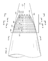
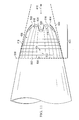
- FIG. 6 an illustration of a side view of core nozzle 406 of nozzle system 403 is depicted in accordance with an illustrative embodiment. As illustrated, all curves in plurality of curves 506 begin at selected axial plane 508.
- FIG. 7 an illustration of an end view of core nozzle 406 is depicted in accordance with an illustrative embodiment.
- an end view of core nozzle 406 taken with respect to lines 7-7 in Figure 6 is depicted.
- outer surface 418 along any axial plane through aft portion 420 of core nozzle 406 has a wavy shape.
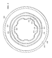
- axial cross-section 800 of core nozzle 406 is a cross-section along an axial plane through core nozzle 406 taken along lines 8A-8A in Figure 6 .
- axial cross-section 802 is a cross-section along an axial plane through core nozzle 406 taken along lines 8B-8B in Figure 6 .
- Axial cross-section 804 is a cross-section along an axial plane through core nozzle 406 taken along lines 8C-18 in Figure 6 .
- Axial cross-section 806 is a cross-section along an axial plane through core nozzle 406 taken along lines 8D-8D in Figure 6 .
- inner surface 810 of core nozzle 406 is depicted in axial cross-section 800, axial cross-section 802, and axial cross-section 804.
- inner surface 810 of core nozzle 406 is depicted as having a shape similar to outer surface 418, inner surface 810 may have some other suitable shape in other illustrative examples.
- inner surface 810 may be substantially circular in each of axial cross-section 800, axial cross-section 802, axial cross-section 804, and axial cross-section 806.
- FIG. 9 an illustration of a cross-sectional view of core nozzle 406 is depicted in accordance with an illustrative embodiment.
- a cross-sectional view of core nozzle 406 taken along lines 9-9 in Figure 7 is depicted.
- Inner surface 810 of core nozzle 406 is seen in this cross-sectional view. Although inner surface 810 of core nozzle 406 is depicted as curving in a manner similar to outer surface 418, inner surface 810 may curve in some other suitable manner, or in some cases, not curve.
- core nozzle 406 may have alternate inner surface 900 instead of inner surface 810.
- core nozzle 406 may have alternate inner surface 902 instead of inner surface 810.
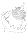
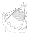
- outer surface 418 of aft portion 420 of core nozzle 406 in Figure 10 has a different shape than outer surface 418 of aft portion 420 of core nozzle 406 in Figures 4-9 .
- outer surface 418 of aft portion 420 of core nozzle 406 in Figure 10 is curved in a manner that is different from the curving of outer surface 418 of aft portion 420 of core nozzle 406 in Figures 4-9 .
- plurality of curves 504 along the different radial planes through core nozzle 406 in Figure 10 have different curvatures than plurality of curves 504 in Figure 5 .
- FIG. 11 an illustration of a side view of core nozzle 406 is depicted in accordance with an illustrative embodiment.
- a side view of core nozzle 406 from Figure 10 is depicted.
- FIG. 12 an illustration of an end view of core nozzle 406 is depicted in accordance with an illustrative embodiment.
- an end view of core nozzle 406 from Figure 10 taken along lines 12-12 is depicted.
- FIG. 13 an illustration of a cross-sectional view of core nozzle 406 is depicted in accordance with an illustrative embodiment.
- a cross-sectional view of core nozzle 406 from Figure 10 is depicted taken along lines 13-13 in Figure 12 .
- FIG. 14 an illustration of a portion of nozzle system 403 is depicted in accordance with an illustrative embodiment.
- fan nozzle 404 of nozzle system 403 is depicted having plurality of extensions 1400.
- plurality of extensions 1400 fan nozzle 404 has trailing edge 1402 instead of trailing edge 412 in Figure 4 .
- Plurality of extensions 1400 may be configured to help reduce noise generated by engine 400.
- FIG 15 an illustration of a portion of nozzle system 403 with a plug having a channel is depicted in accordance with an illustrative embodiment.
- nozzle system 403 uses fan nozzle 404 having plurality of extensions from Figure 14 .
- nozzle system 403 uses plug 1500 instead of plug 408 from Figure 4 .
- plug 1500 has channel 1502 configured to vent gases.
- plug 1500 has plurality of extensions 1504.
- FIG. 16 an illustration of a side view of a portion of nozzle system 403 with plug 1500 having channel 1502 is depicted in accordance with an illustrative embodiment. As depicted, outer surface 1600 of aft portion 1602 of plug 1500 is not curved.
- FIG. 17 an illustration of a portion of nozzle system 403 with plug 1500 having channel 1502 is depicted in accordance with an illustrative example.
- outer surface 1600 of aft portion 1602 of plug 1500 is curved along a plurality of longitudinal lines through center axis 410.
- the shape of aft portion 1602 of plug 1500 may be a shape similar to the shape of core nozzle 406 in Figures 4 and 5 . This configuration for plug 1500 may help reduce shock-cell noise when the jet stream between core nozzle 406 and plug 1500 is supersonic.
- FIG 18 an illustration of a side view of nozzle system 403 with plug 1500 having channel 1502 is depicted in accordance with an illustrative example. As depicted, nozzle system 403 in Figure 17 , with plug 1500 having channel 1502 and with outer surface 1600 of aft portion 1602 curved, is depicted.
- FIG 19 an illustration of a portion of nozzle system 403 with a plug having a different shape is depicted in accordance with an illustrative embodiment.
- nozzle system 403 uses plug 1900 instead of plug 1500 in Figures 15-18 or plug 408 in Figure 4 .
- Plug 1900 has channel 1902 and plurality of extensions 1904.
- core nozzle 406 has been depicted as extending aftwards past trailing edge 412 of fan nozzle 404, fan nozzle 404 may extend aftwards past trailing edge 414 of core nozzle 406 in some illustrative examples.
- a plug may be optional for nozzle system 403.
- aircraft 2000 is an example of one implementation for aerospace vehicle 105 in Figure 1 .
- Aircraft 2000 has wing 2002 and wing 2004 attached to body 2006.
- Aircraft 2000 includes engine 2008 attached to wing 2002 and engine 2010 attached to wing 2004.
- Engine 2008 and engine 2010 may be examples of one implementation for engine 102 in Figure 1 .
- Body 2006 of aircraft 2000 has tail section 2012.
- Horizontal stabilizer 2014, horizontal stabilizer 2016, and vertical stabilizer 2018 are attached to tail section 2012 of body 2006.
- engine 2008 has nozzle system 2020
- engine 2010 has nozzle system 2022
- Nozzle system 2020 and nozzle system 2022 may have the same configuration as nozzle system 403 in Figure 14 with fan nozzle 404 having plurality of extensions 1400, core nozzle 406 having outer surface 418 of aft portion 420 of core nozzle 406 curved, and plug 408.
- FIG. 21 an illustration of a process for reducing noise generated by an engine in the form of a flowchart is depicted in accordance with an illustrative embodiment.
- the process illustrated in Figure 30 may be implemented using nozzle system 100 for engine 102 in Figure 1 and/or the different configurations for nozzle system 403 described in Figures 4-19 .
- the process begins by operating an engine (operation 2100).
- the engine comprises a first nozzle and a second nozzle.
- the second nozzle is at least partially surrounded by the first nozzle.
- An outer surface of an aft portion of the second nozzle has a shape configured such that a radial cross-section of the outer surface of the aft portion of the second nozzle has a curve that is different from at least one other curve for another radial cross-section of the outer surface of the aft portion of the second nozzle.
- the engine may generate exhaust that exits the nozzle system as an exhaust jet.
- the exhaust jet comprises a first jet stream that exits the first nozzle and a second jet stream that exits the second nozzle.
- the first jet stream may exit the first nozzle at a first supersonic speed and the second jet stream may exit the second nozzle at one of a second supersonic speed or a subsonic speed.
- the process then reduces noise generated during operation of the engine using the second nozzle of the nozzle system (operation 2101), with the process terminating thereafter.
- the shape of the outer surface of the aft portion of the second nozzle is selected to reduce shock-cell noise associated with a shock-cell pattern that forms in the first jet stream when the first jet stream exits the nozzle system at supersonic speeds.
- each block in the flowchart or block diagram may represent a module, segment, function, and/or a portion of an operation or step.
- one or more of the blocks may be implemented as program code, in hardware, or a combination of the program code and hardware.
- the function or functions noted in the blocks may occur out of the order noted in the figures.
- two blocks shown in succession may be executed substantially concurrently or the blocks may sometimes be performed in the reverse order, depending upon the functionality involved.
- other blocks may be added in addition to the illustrated blocks in a flowchart or block diagram.
- an apparatus comprises a first nozzle and a second nozzle at least partially surrounded by the first nozzle.
- An outer surface of an aft portion of the second nozzle has a shape configured such that a radial cross-section of the outer surface of the aft portion of the second nozzle has a curve that is different from at least one other curve for another radial cross-section of the outer surface of the aft portion of the second nozzle.
Landscapes
- Engineering & Computer Science (AREA)
- Chemical & Material Sciences (AREA)
- Combustion & Propulsion (AREA)
- Mechanical Engineering (AREA)
- General Engineering & Computer Science (AREA)
- Aviation & Aerospace Engineering (AREA)
- Jet Pumps And Other Pumps (AREA)
- Nozzles (AREA)
Abstract
Description
- The present disclosure relates generally to engines and, in particular, to a method and apparatus for reducing noise generated during operation of an engine. Still more particularly, the present disclosure relates to a method and apparatus for reducing noise generated by the exhaust jet of an engine.
- An aircraft may generate different types of noise during different phases of flight. These different phases of flight may include taxiing, takeoff, landing, cruising, ascending, descending, and/or other phases of flight. In some cases, the noise generated by an aircraft may be undesirable to the passengers and/or crew onboard the aircraft. For example, noise generated during a cruise phase of flight may be undesirable to the passengers and/or crew of an aircraft.
- One source of the noise generated during operation of an aircraft may be the operation of an engine of the aircraft. In particular, the flow of exhaust exiting an engine of an aircraft during operation of the engine may contribute to the undesirable noise produced during operation of an aircraft. The flow of exhaust exiting an engine is referred to as an exhaust jet. The exhaust jet is a stream of exhaust gases that flow out of the engine through a nozzle system for the engine. This stream of gases is used to move the aircraft. The pattern with which the exhaust jet flows out of the nozzle system may be referred to as an exhaust plume.
- When the exhaust jet exits the nozzle system at supersonic speeds and when the exhaust jet exiting the nozzle has a pressure that is different from the pressure of the ambient air around the exhaust jet, a shock-cell pattern may form in the exhaust jet. This shock-cell pattern may be one factor that contributes to the noise generated during operation of an engine of an aircraft. The noise associated with this shock-cell pattern is referred to as shock-associated broadband noise or shock-cell noise.
- A number of different mechanisms have been used to reduce the amount of noise generated during operation of an engine. These mechanisms include adding chevrons and/or serrations to one or more nozzles in the nozzle system for the engine. However, these currently available mechanisms for reducing the noise generated by an engine may not reduce the noise to within selected tolerances. In particular, currently available mechanisms may not reduce the shock-cell noise generated by an engine during a cruise phase of flight to within selected tolerances.
- Therefore, it would be desirable to have a method and apparatus that takes into account one or more of the issues discussed above as well as possibly other issues.
- In one illustrative embodiment, a nozzle system comprises a first nozzle and a second nozzle at least partially surrounded by the first nozzle. An outer surface of an aft portion of the second nozzle has a shape configured such that a radial cross-section of the outer surface of the aft portion of the second nozzle has a curve that is different from at least one other curve for another radial cross-section of the outer surface of the aft portion of the second nozzle and such that an axial cross-section of the outer surface of the aft portion of the second nozzle has a wavy shape.
- In another illustrative embodiment, an engine comprises a housing and a nozzle system at an aft end of the housing for the engine. The nozzle system comprises a fan nozzle and a core nozzle. The core nozzle is at least partially surrounded by the fan nozzle. An outer surface of an aft portion of the core nozzle has a shape that is selected to reduce noise generated during operation of the engine. The shape of the outer surface of the aft portion of the core nozzle is configured such that a radial cross-section of the outer surface of the aft portion of the core nozzle has a curve that is different from at least one other curve for another radial cross-section of the outer surface of the aft portion of the core nozzle and such that an axial cross-section of the outer surface of the aft portion of the second nozzle has a wavy shape.
- In yet another illustrative embodiment, a method for reducing noise generated by an engine is provided. The engine is operated. The engine has a nozzle system comprising a first nozzle and a second nozzle. The second nozzle is at least partially surrounded by the first nozzle. An outer surface of an aft portion of the second nozzle has a shape configured such that a radial cross-section of the outer surface of the aft portion of the second nozzle has a curve that is different from at least one other curve for another radial cross-section of the outer surface of the aft portion of the second nozzle. The noise generated during operation of the engine is reduced using the second nozzle of the nozzle system and such that an axial cross-section of the outer surface of the aft portion of the second nozzle has a wavy shape.
- The features, functions, and benefits can be achieved independently in various embodiments of the present disclosure or may be combined in yet other embodiments in which further details can be seen with reference to the following description and drawings.
- The novel features believed characteristic of the illustrative embodiments are set forth in the appended claims. The illustrative embodiments, however, as well as a preferred mode of use, further objectives, and features thereof will best be understood by reference to the following detailed description of an illustrative embodiment of the present disclosure when read in conjunction with the accompanying drawings, wherein:
-
Figure 1 is an illustration of a nozzle system for an engine in accordance with an illustrative embodiment; -
Figure 2 is an illustration of a center axis for nozzle system and different axial planes and radial axes relative to the center axis in accordance with an illustrative embodiment; -
Figure 3 is an illustration of a shape for the outer surface of a nozzle in accordance with an illustrative embodiment; -
Figure 4 is an illustration of a perspective view of an engine for an aircraft in accordance with an illustrative embodiment; -
Figure 5 is an illustration of a perspective view of a core nozzle of a nozzle system in accordance with an illustrative embodiment; -
Figure 6 is an illustration of a side view of a core nozzle of a nozzle system in accordance with an illustrative embodiment; -
Figure 7 is an illustration of an end view of a core nozzle in accordance with an illustrative embodiment; -
Figure 8 is an illustration of axial slices through a core nozzle in accordance with an illustrative embodiment; -
Figure 9 is an illustration of a cross-sectional view of a core nozzle in accordance with an illustrative embodiment; -
Figure 10 is an illustration of another configuration for a core nozzle in accordance with an illustrative embodiment; -
Figure 11 is an illustration of a side view of a core nozzle in accordance with an illustrative embodiment; -
Figure 12 is an illustration of an end view of a core nozzle in accordance with an illustrative embodiment; -
Figure 13 is an illustration of a cross-sectional view of a core nozzle in accordance with an illustrative embodiment; -
Figure 14 is an illustration of a portion of a nozzle system in accordance with an illustrative embodiment; -
Figure 15 is an illustration of a portion of a nozzle system with a plug having a channel in accordance with an illustrative embodiment; -
Figure 16 is an illustration of a side view of a portion of a nozzle system with a plug having a channel in accordance with an illustrative embodiment; -
Figure 17 is an illustration of a portion of a nozzle system with a plug having a channel in accordance with an illustrative embodiment; -
Figure 18 is an illustration of a side view of a nozzle system with a plug having a channel in accordance with an illustrative embodiment; -
Figure 19 is an illustration of a portion of a nozzle system with a different type of plug in accordance with an illustrative embodiment; -
Figure 20 is an illustration of an aircraft in accordance with an illustrative embodiment; and -
Figure 21 is an illustration of a process for reducing noise generated by an engine in the form of a flowchart in accordance with an illustrative embodiment. - The different illustrative embodiments recognize and take into account different considerations. For example, the different illustrative embodiments recognize and take into account that noise, including shock-cell noise, produced by an engine during operation of an aircraft may be undesirable. The noise produced by an engine of an aircraft may be undesirable to the passengers and/or crew onboard the aircraft while the aircraft is in flight.
- The different illustrative embodiments recognize and take into account that it may be desirable to have a nozzle system that is configured to reduce noise, and in particular, shock-cell noise, to within selected tolerances. Thus, the different illustrative embodiments provide a method and apparatus for reducing noise generated during operation of a propulsion system.
- Referring now to the figures, and in particular, with reference to
Figure 1 , an illustration of a nozzle system for an engine is depicted in the form of a block diagram in accordance with an illustrative embodiment. In these illustrative examples,nozzle system 100 is part ofengine 102. -
Engine 102 may be configured for use inplatform 104. In these illustrative examples,platform 104 isaerospace vehicle 105.Aerospace vehicle 105 may be selected from one of an aircraft, a jet aircraft, a missile, a spacecraft, a space shuttle, or some other suitable type of vehicle configured for travel in air and/or space. Of course, in other illustrative examples,platform 104 may be some other suitable type of mobile platform configured to move usingengine 102. In still other illustrative examples,engine 102 may be configured for use in a stationary platform. For example,engine 102 may be used in a power generation system. - As depicted,
engine 102 may take the form ofpropulsion system 103 whenplatform 104 isaerospace vehicle 105. As used herein, a "propulsion system" is any system configured to produce thrust to push an object forward. For example,engine 102 may be a jet engine. More specifically,engine 102 may be a turbofan engine. Of course, in other illustrative examples,engine 102 may be a turbojet engine, a rocket engine, or some other suitable type of propulsion system foraerospace vehicle 105. -
Propulsion system 103 is configured to generate and expelexhaust 106 throughnozzle system 100 to generate the thrust needed to moveplatform 104. The flow ofexhaust 106 exitingnozzle system 100 is exhaust jet 107 in these illustrative examples. The shape and/or pattern of exhaust jet 107 exitingnozzle system 100 may be referred to as the exhaust plume forpropulsion system 103. - As depicted in these examples, exhaust jet 107 comprises
first jet stream 108 andsecond jet stream 110 that exitpropulsion system 103 throughnozzle system 100 at substantially the same time.First jet stream 108 is a first flow ofexhaust 106 that exitspropulsion system 103 throughfirst nozzle 112 ofnozzle system 100.Second jet stream 110 is a second flow ofexhaust 106 that exitspropulsion system 103 throughsecond nozzle 114 ofnozzle system 100. - In these illustrative examples,
first nozzle 112 may befan nozzle 116. Further,second nozzle 114 may becore nozzle 118 in these examples. In some cases,second nozzle 114 may be referred to as a primary nozzle, whilefirst nozzle 112 may be referred to as a secondary nozzle. In still other illustrative examples,first nozzle 112 may befan nozzle 116, whilesecond nozzle 114 may be a vent nozzle associated with a core nozzle. This vent nozzle may be referred to as a tertiary nozzle or a tertiary vent nozzle. -
First nozzle 112 at least partially surroundssecond nozzle 114. In other words,second nozzle 114 may be located withinfirst nozzle 112. In one illustrative example,second nozzle 114 is nested withinfirst nozzle 112. In other words,first nozzle 112 andsecond nozzle 114 may be substantially concentric to each other. For example, center axis 113 may be a center axis for bothfirst nozzle 112 andsecond nozzle 114. Of course, in other illustrative examples, center axis 113 may only be a center axis forsecond nozzle 114, andfirst nozzle 112 may have a different center axis substantially parallel to but offset from center axis 113. - Depending on the implementation,
first nozzle 112 may extend downstream ofsecond nozzle 114 orsecond nozzle 114 may extend downstream offirst nozzle 112. Whenplatform 104 isaerospace vehicle 105, "downstream", as used herein, is towards an aft end ofaerospace vehicle 105. As used herein, "upstream" is towards a forward end ofaerospace vehicle 105. - In some illustrative examples,
nozzle system 100 may include plug 115 in addition tofirst nozzle 112 andsecond nozzle 114. Whennozzle system 100 includesplug 115, plug 115 is nested withinsecond nozzle 114. In other words, plug 115 may share center axis 113 withfirst nozzle 112 2 andsecond nozzle 114. Of course, in other illustrative examples, plug 115 may have a different center axis that is substantially parallel to but offset from center axis 113. - Depending on the implementation, plug 115 may have
channel 117.Channel 117 may be present inplug 115 to vent gases generated bypropulsion system 103. This flow ofgases exiting channel 117 inplug 115 isvent stream 119. - In these illustrative examples, with
second nozzle 114 located withinfirst nozzle 112,second jet stream 110 is surrounded byfirst jet stream 108 as these two jet streams exitnozzle system 100.Inner shear layer 121 is formed at the interface betweenfirst jet stream 108 andsecond jet stream 110.Outer shear layer 122 is formed at the interface betweenfirst jet stream 108 and the air around exhaust jet 107. In some cases,outer shear layer 122 may be at least partially formed by a mixture offirst jet stream 108 andsecond jet stream 110, as well as the air around exhaust jet 107. Further, whennozzle system 100 includesplug 115 and plug 115 includeschannel 117,additional shear layer 124 is formed betweenfirst jet stream 108 andvent stream 119. - During operation of
propulsion system 103,first jet stream 108 and/orsecond jet stream 110 may exitnozzle system 100 at speeds greater than the speed of sound. At supersonic speeds, shock-cell pattern 120 may form withinfirst jet stream 108 and/orsecond jet stream 110. Shock-cell pattern 120 comprises shock-cells, also referred to as shock diamonds or shock-cell diamonds, within exhaust jet 107 that may be visible. Shock-cells or shock-cell diamonds are a formation of stationary wave patterns that appear in a jet stream. - Shock-
cell pattern 120 is formed when a jet stream that exitsnozzle system 100 is supersonic and is either over-expanded or under-expanded. The jet stream is over-expanded when the static pressure of the jet stream exiting a nozzle is less than the static pressure of the flow of air and/or exhaust surrounding that jet stream. The jet stream is under-expanded when the pressure of the jet stream exiting the nozzle is greater than the pressure of the flow of air and/or exhaust surrounding that jet stream. Typically, a jet stream may be under-expanded at cruise conditions at high altitudes. - When a jet stream is either over-expanded or under-expanded, the pressure in the jet stream where the jet stream exits
nozzle system 100 begins either compressing or expanding. When the jet stream isfirst jet stream 108, compression or expansion waves are formed that reflect betweenouter shear layer 122 andinner shear layer 121 in a manner that causes shock-cells to form infirst jet stream 108. Whensecond jet stream 110 encounters a similar situation, shock-cells are formed insecond jet stream 110. - When shock-
cell pattern 120 is formed withinfirst jet stream 108 and/orsecond jet stream 110,noise 126 generated during operation ofpropulsion system 120 includes shock-cell noise 128.Noise 126 is the noise associated with the flow ofexhaust 106 fromnozzle system 100. In other words,noise 126 is the noise associated with exhaust jet 107 exitingnozzle system 100. In some illustrative examples, shock-cell noise 128 also may be referred to as shock-associated broadband noise. -
Nozzle system 100 is configured to reducenoise 126, and in particular, shock-cell noise 128, to within selected tolerances. As one illustrative example,second nozzle 114 ofnozzle system 100 is configured to reduce shock-cell noise 128 generated during a cruise phase of flight foraerospace vehicle 105 to within selected tolerances. Of course, in other illustrative examples,nozzle system 100 may be configured to reduce shock-cell noise 128 generated during other phases of flight. - As depicted in
Figure 1 ,second nozzle 114 hasinner surface 130 andouter surface 132. Further, in these illustrative examples,second nozzle 114 includes plurality ofextensions 143 configured to extend aftwards fromexit boundary 140 alongouter surface 132. Each extension in plurality ofextensions 143 may have a base that lies alongexit boundary 140 ofouter surface 132 and a tip located downstream ofexit boundary 140. - Plurality of
extensions 143 may be referred to as, for example, without limitation, serrations or chevrons. Depending on the implementation, these extensions may have a trapezoidal shape, a triangular shape, or some other suitable type of shape. Plurality ofextensions 143 may be configured to reducenoise 126. - In these illustrative examples, plurality of
extensions 143 may be part ofaft portion 135 ofsecond nozzle 114.Aft portion 135 ofsecond nozzle 114 is the portion ofsecond nozzle 114 between selectedaxial plane 138 throughsecond nozzle 114 and aftmostaxial plane 136 throughsecond nozzle 114. As used herein, an "axial plane" throughsecond nozzle 114, such as aftmostaxial plane 136 or selectedaxial plane 138, is a plane throughsecond nozzle 114 that is substantially perpendicular to center axis 113 throughsecond nozzle 114. - Selected
axial plane 138 may be any axial plane throughsecond nozzle 114 that is located upstream of plurality ofextensions 143. In other words, none of the extensions in plurality ofextensions 143 may have a portion located upstream of selectedaxial plane 138. In some cases,exit boundary 140 from which plurality ofextensions 143 extend may be contained within a single axial plane throughsecond nozzle 114. In other illustrative examples,exit boundary 140 may span more than one axial plane throughsecond nozzle 114. - Aftmost
axial plane 136 is the axial plane throughsecond nozzle 114 located at the aftmost portion of trailingedge 142 ofsecond nozzle 114. Trailingedge 142 is the aft edge wheresecond nozzle 114 ends. At least a portion of trailingedge 142 is formed by the aft edges of the extensions in plurality ofextensions 143. Aftmostaxial plane 136 may be the axial plane through the aftmost tip of the tips of plurality ofextensions 143. - In these illustrative examples,
outer surface 132 ofaft portion 135 ofsecond nozzle 114 hasshape 133 configured to reduce shock-cell noise 128. In particular,shape 133 of the portion ofouter surface 132 between selectedaxial plane 138 and aftmostaxial plane 136 is configured such that a radial cross-section of this portion ofouter surface 132 throughsecond nozzle 114 is curved. - As used herein, "radial cross-section" through
second nozzle 114 is a cross-section through a radial plane throughsecond nozzle 114. Further, a "radial plane" throughsecond nozzle 114, as used herein, is any plane throughsecond nozzle 114 that includes center axis 113. In other words, a radial plane is a plane in which center axis 113 lies. - In these illustrative examples,
shape 133 is configured such that a radial cross-section of the portion ofouter surface 132 between selectedaxial plane 138 and aftmostaxial plane 136 has a curve that is different from at least one other curve for another radial cross-section of the portion ofouter surface 132 between selectedaxial plane 138 and aftmostaxial plane 136. - In this manner,
shape 133 of the portion ofouter surface 132 withinaft portion 135 ofsecond nozzle 114 is configured such that different radial cross-sections of this portion ofouter surface 132 may have different curves. Further, in these illustrative examples, any radial cross-section of the portion ofouter surface 132 located upstream of selectedaxial plane 138 ofsecond nozzle 114 may not be curved. Instead, this radial cross-section may be substantially linear. - An "axial cross-section" through
second nozzle 114, as used herein, is a cross-section through an axial plane throughsecond nozzle 114. Whensecond nozzle 114 has plurality ofextensions 143, axial cross-sections ofouter surface 132 ofsecond nozzle 114 at and upstream ofexit boundary 140 are continuous. Further, axial cross-sections ofouter surface 132 ofsecond nozzle 114 downstream ofexit boundary 140 may be discontinuous. - In these illustrative examples,
shape 133 of the portion ofouter surface 132 ofsecond nozzle 114 between selectedaxial plane 138 and trailingedge 142 causes different axial cross-sections ofouter surface 132 throughaft portion 135 ofsecond nozzle 114 to be non-circular, and in some cases, non-symmetrical. In particular, an axial cross-section ofouter surface 132 along an axial plane between selectedaxial plane 138 and trailingedge 142 may be non-axisymmetrical.Shape 133 is configured such that the axial cross-section ofouter surface 132 along an axial plane between selectedaxial plane 138 and aftmostaxial plane 136 has a wavy shape. - In particular, the axial cross-section of
outer surface 132 between selectedaxial plane 138 and aftmostaxial plane 136 may be a wavy shape comprising at least one of hills and valleys with respect to center axis 113 throughsecond nozzle 114. In other words, the axial cross-section ofouter surface 132 may have a wavy shape that comprises hills, valleys, or a combination of the two when viewed from center axis 113. - When the axial cross-section of
outer surface 132 ofaft portion 135 ofsecond nozzle 114 is taken along an axial plane downstream of the most forward portion ofexit boundary 140, the wavy shape may be discontinuous. Depending on the implementation, only hills or only valleys may be seen with this type of axial cross-section. -
Curve 144 is an example of a curve for a radial cross-section ofouter surface 132 ofaft portion 135 ofsecond nozzle 114. In these illustrative examples,curve 144 is for the radial cross-section ofouter surface 132 ofaft portion 135 ofsecond nozzle 114 alongradial plane 146.Curve 144 begins at selectedaxial plane 138 and ends at trailingedge 142. -
Curve 144 may have number ofportions 148 with number ofcurvatures 150. As used herein, a "number of" items means one or more items. For example, number ofportions 148 means one or more portions. Each portion in number ofportions 148 has a corresponding curvature in number ofcurvatures 150. - As used herein, a "curvature" of a curve, such as
curve 144, at any point, P, alongcurve 144 is defined as the reciprocal of the radius of the circle that most closely approximatescurve 144 at or near that point, P. This circle may be referred to as an "osculating circle." The curvature of this point, P, is the rate of change of the angle of the tangent at the point, P, oncurve 144 per unit length ofcurve 144. - When the osculating circle tangential to the point, P, along
curve 144 is located on the side ofcurve 144 facing center axis 113, the curvature at this point, P, may be referred to as being "convex," with respect to the flow overouter surface 132. When the osculating circle tangential to the point, P, alongcurve 144 is located on the side ofcurve 144 facingfirst nozzle 112, the curvature at this point, P, may be referred to as being "concave," with respect to the flow overouter surface 132. In this manner, the different curvatures alongcurve 144 may be concave curvatures, convex curvatures, or some combination of the two. - In one illustrative example, the curvature at all points along
curve 144 may be the same. In another illustrative example, the curvature at different points alongcurve 144 may be different. In some cases, the curvature alongcurve 144 may continuously change between selectedaxial plane 138 and trailingedge 142. In this manner,shape 133 forouter surface 132 ofaft portion 135 ofsecond nozzle 114 may take a number of different forms, depending on the implementation. - In the different illustrative examples,
shape 133 formed by the different curvatures selected for the different curves forouter surface 132 ofaft portion 135 ofsecond nozzle 114 are selected to reduce shock-cell noise 128 to within selected tolerances. In particular, whenplatform 104 isaerospace vehicle 105,shape 133 may be selected to reduce shock-cell noise 128 associated with shock-cell pattern 120 infirst jet stream 108 and/orsecond jet stream 110 to within selected tolerances during a cruise phase of flight and/or other phases of flight foraerospace vehicle 105. - In some illustrative examples, an outer surface of an aft portion of
first nozzle 112 may have a shape configured similar toshape 133 ofouter surface 132 ofaft portion 135 ofsecond nozzle 114. This shape may be configured to reduce shock-cell noise 128 if shock-cells are formed in the air aroundfirst jet stream 108 whenaerospace vehicle 105 is travelling at supersonic speeds. - For example,
first nozzle 112 may have a plurality of extensions. Whenfirst nozzle 112 has the plurality of extensions, the shape of the outer surface of an aft portion offirst nozzle 112 may be configured such that a particular curve for a radial cross-section of the outer surface offirst nozzle 112 throughfirst nozzle 112 is different from a curve for at least one other radial cross-section of the outer surface offirst nozzle 112. - In still other illustrative examples, when
nozzle system 100 includesplug 115 withchannel 117, an outer surface of an aft portion ofplug 115 may have a shape similar toshape 133 ofouter surface 132 ofaft portion 135 ofsecond nozzle 114. This shape may be configured to reduce shock-cell noise 128 associated withsecond jet stream 110. - For example, plug 115 may have a plurality of extensions. When
plug 115 has the plurality of extensions, the shape of the outer surface of an aft portion ofplug 115 may be configured such that a particular curve for a radial cross-section of the outer surface ofplug 115 throughplug 115 is different from a curve for at least one other radial cross-section of the outer surface ofplug 115. - In this manner, the shapes of the outer surfaces of the different nozzles in
nozzle system 100 may be configured in a number of different ways to reduce shock-cell noise 128 to within selected tolerances. In particular, the outer surface of the aft portion of at least one offirst nozzle 112,second nozzle 114, and plug 115 may have a shape configured to reduce shock-cell noise 128. - The illustration of
nozzle system 100 inFigure 1 is not meant to imply physical or architectural limitations to the manner in which an illustrative embodiment may be implemented. Other components in addition to and/or in place of the ones illustrated may be used. Some components may be unnecessary. Also, the blocks are presented to illustrate some functional components. One or more of these blocks may be combined, divided, or combined and divided into different blocks when implemented in an illustrative embodiment. - For example, in some illustrative examples,
nozzle system 100 may not includeplug 115. In other illustrative examples,second nozzle 114 may not have plurality ofextensions 143. In some cases, the different extensions in plurality ofextensions 143 may have different lengths taken from the base to the tip of an extension. - In other illustrative examples, a third nozzle may be associated with
second nozzle 114. This third nozzle may be a vent nozzle associated withouter surface 132 ofsecond nozzle 114. Depending on the implementation, an outer surface of an aft portion of this third nozzle may have a shape configured similar toshape 133 forouter surface 132 ofaft portion 135 ofsecond nozzle 115. The shape of the outer surface of the aft portion of this third nozzle may be configured to help reduce shock-cell noise 128. - In some cases, different curves for
outer surface 132 ofaft portion 135 ofsecond nozzle 114 along different radial planes throughsecond nozzle 114 may begin at different selected axial planes through second nozzle. For example, in one illustrative example, one curve may begin at selectedaxial plane 138 and another curve may begin at an axial plane located downstream of selectedaxial plane 138. - With reference now to
Figure 2 , an illustration of a center axis for nozzle system and different axial planes and radial axes relative to the center axis is depicted in accordance with an illustrative embodiment. In this depicted example,center axis 200 is an example of center axis 113 inFigure 1 . In this manner,center axis 200 may be a center axis fornozzle system 100 inFigure 1 . For example,first nozzle 112,second nozzle 114, and plug 115 inFigure 1 may be substantially concentric to each other with respect to center axis 113. -
Axial planes 202 are planes perpendicular tocenter axis 200.Axial planes 202 includeaxial plane 204,axial plane 206,axial plane 208,axial plane 210, andaxial plane 211.Axial plane 204 may be an example of selectedaxial plane 138 inFigure 1 .Axial plane 211 may be an example of aftmostaxial plane 136 inFigure 1 . In one illustrative example,exit boundary 140 inFigure 1 may be contained withinaxial plane 210. - Axial cross-sections of
outer surface 132 ofaft portion 135 ofsecond nozzle 114 inFigure 1 taken alongaxial planes 202 may appear non-circular and non-symmetrical whenouter surface 132 ofaft portion 135 ofsecond nozzle 114 hasshape 133 inFigure 1 . However, axial cross-sections ofouter surface 132 ofsecond nozzle 114 inFigure 1 taken along any axial planes throughsecond nozzle 114 upstream ofaxial plane 204 may appear substantially circular and symmetrical. - As depicted,
radial axes 212 are axes that intersectcenter axis 200. Radial axes 212 includeradial axis 214,radial axis 216, andradial axis 218. The plane formed by one of these radial axis andcenter axis 200 is referred to as a radial plane. For example, the plane formed byradial axis 214 andcenter axis 200 is an example of one implementation forradial plane 146 inFigure 1 . - When
outer surface 132 ofaft portion 135 ofsecond nozzle 114 hasshape 133 inFigure 1 , the radial cross-sections ofouter surface 132 ofaft portion 135 may have different curves. For example, the radial cross-section ofouter surface 132 ofaft portion 135 ofsecond nozzle 114 taken along the radial plane formed byradial axis 214 andcenter axis 200 may have a curve that is different from the curve for the radial cross-section ofouter surface 132 ofaft portion 135 ofsecond nozzle 114 along the radial plane formed byradial axis 216 andcenter axis 200. - In other illustrative examples,
axial planes 202 and the radial planes formed byradial axes 212 andcenter axis 200 may be forfirst nozzle 112 inFigure 1 . In still other illustrative examples,axial planes 202 and the radial planes formed byradial axes 212 andcenter axis 200 may be for a plug, such asplug 115 inFigure 1 , instead of a nozzle. - Turning now to
Figure 3 , an illustration of a shape for the outer surface of a nozzle is depicted in accordance with an illustrative embodiment. In this illustrative example,aft portion 300 ofcore nozzle 302 is a representation of one example of an implementation foraft portion 135 ofcore nozzle 118 inFigure 1 . As depicted,core nozzle 302 has plurality ofextensions 304. Plurality ofextensions 304 includesextension 305 andextension 307. -
Axial plane 306,axial plane 308,axial plane 310, andaxial plane 312 are axial planes throughaft portion 300 ofnozzle 302.Axial plane 306 is an example of selectedaxial plane 138 inFigure 1 .Axial plane 312 is an example of aftmostaxial plane 138 inFigure 1 .Aft portion 300 ofcore nozzle 302 is the portion ofcore nozzle 302 betweenaxial plane 306 andaxial plane 312. - In this illustrative example,
outer surface 314 ofaft portion 300 ofcore nozzle 302 hasshape 315.Shape 315 is configured such that different radial cross-sections ofouter surface 314 have different curves. In this illustrative example,shape 315 is configured such thatportion 326 ofouter surface 314 has substantially the same shape asportion 328 ofouter surface 314. -
Curves 316 are examples of curves forouter surface 314 ofaft portion 300 ofcore nozzle 302 along different radial planes throughcore nozzle 302. As depicted in this example, all ofcurves 316 forouter surface 314 begin ataxial plane 306 and end at trailingedge 318 ofcore nozzle 302.Curve 320,curve 322, andcurve 324 are examples ofcurves 316. These three curves lie along different radial planes throughcore nozzle 302. - In this illustrative example, the different curvatures along the different curves for the portion of
outer surface 314 at and neartip 334 ofextension 305 are selected such that an axial cross-section of this portion ofouter surface 314 at and neartip 334 ofextension 336 appears as a hill. Further, the different curvatures along the different curves for the portion ofouter surface 314 at and nearinterface 336 betweenextension 305 andextension 307 are selected such that an axial cross-section of this portion ofouter surface 314 at and near interface appears 336 as a valley. - In this illustrative example,
shape 315 is configured such that the curvature along a curve incurves 316 is different from the curvature along other curves incurves 316 beginning ataxial plane 306. However, in other illustrative examples,outer surface 314 ofaft portion 300 ofcore nozzle 314 may have a shape configured such that all curves along all radial planes throughcore nozzle 302 have the same selected curvature betweenaxial plane 306 andboundary 330. In other words, in these other illustrative examples,outer surface 314 ofaft portion 300 may have a shape configured such that the curvatures alongcurve 320,curve 322, andcurve 324 are the same up untilboundary 330 and different downstream ofboundary 330 up until trailingedge 318. - In still other illustrative examples,
outer surface 314 ofaft portion 300 ofcore nozzle 314 may have a shape configured such that all curves along all radial planes throughcore nozzle 302 have the same selected curvature betweenaxial plane 306 andboundary 332. In other words, in these other illustrative examples,outer surface 314 ofaft portion 300 may have a shape configured such that the curvatures alongcurve 320,curve 322, andcurve 324 are the same up untilboundary 332 and different downstream ofboundary 330 up until trailingedge 318. With reference now toFigures 4-20 , illustrations of different configurations for a nozzle system for an engine are depicted in accordance with an illustrative embodiment.Engine 400 inFigures 4-20 may be implemented in an aerospace vehicle, such asaerospace vehicle 105 inFigure 1 .Engine 400 may be an example ofengine 102 inFigure 1 . In particular,engine 400 may be implemented in a jet aircraft. In these illustrative examples,engine 400 is a turbofan engine. The different configurations fornozzle system 400 forengine 400 are selected to reduce noise generated byengine 400 during operation ofengine 400. More specifically, these different configurations fornozzle system 403 are selected to reduce shock-cell noise. - Turning now to
Figure 4 , an illustration of a perspective view of an engine for an aircraft is depicted in accordance with an illustrative embodiment. In this illustrative example,engine 400 includesnacelle 402 andnozzle system 403.Nacelle 402 is a housing forengine 400.Nozzle system 403 is an example of one implementation fornozzle system 100 inFigure 1 .Nozzle system 403 is located at an aft end ofnacelle 402. -
Nozzle system 403 includesfan nozzle 404,core nozzle 406, and plug 408.Fan nozzle 404 is an example of one implementation forfan nozzle 112 inFigure 1 .Core nozzle 406 is an example of one implementation forcore nozzle 114 inFigure 1 . Further, plug 408 is an example of one implementation forplug 115 inFigure 1 . As depicted, plug 408 has a conical shape in this example. -
Fan nozzle 404 andcore nozzle 406 allow exhaust generated during operation ofengine 400 to exitengine 400 in the form an exhaust jet. In this illustrative example,core nozzle 406 is nested withinfan nozzle 404.Plug 408 is nested withincore nozzle 406. - As depicted, plug 408,
core nozzle 406, andfan nozzle 404share center axis 410. Of course, in other illustrative examples, the center axis forplug 408,core nozzle 406, andfan nozzle 404 may be substantially parallel but offset from each other. -
Fan nozzle 404 has trailingedge 412. Further,core nozzle 406 has trailingedge 414 formed by plurality ofextensions 416. Plurality ofextensions 416 are an example of one implementation for plurality of extensions 53 inFigure 1 . Plurality ofextensions 416 may also be referred to as a plurality of chevrons or a plurality of serrations in some cases. -
Core nozzle 406 hasouter surface 418. The shape ofouter surface 418 ofaft portion 420 ofcore nozzle 406 is configured such thatouter surface 418 ofaft portion 420 is curved. The shape ofouter surface 418 is described in greater detail in the figures below. - Turning now to
Figure 5 , an illustration of a perspective view ofcore nozzle 406 ofnozzle system 403 is depicted in accordance with an illustrative embodiment. An enlarged view ofcore nozzle 406 fromFigure 4 is depicted inFigure 5 . In this illustrative example,azimuthal lines 500 andlongitudinal lines 502 onouter surface 418 ofcore nozzle 406 are contour lines that indicate the shape ofouter surface 418 ofaft portion 420 ofcore nozzle 406. -
Azimuthal lines 500 lie along axial planes throughcore nozzle 406.Longitudinal lines 502 lie along radial planes throughcore nozzle 406. As depicted,outer surface 418 ofaft portion 420 ofcore nozzle 406 is curved. For example,outer surface 418 has plurality ofcurves 504 that lie along a plurality of radial planes throughcenter axis 410. - The shape of
outer surface 418 formed by plurality ofcurves 504 is indicated bylongitudinal lines 502 depicted onouter surface 418. For example,longitudinal line 506 indicates the shape ofcurve 510 ofouter surface 418 beginning at selectedaxial plane 508 and ending at trailingedge 414. Selectedaxial plane 508 coincides withazimuthal line 507 in this example. In this illustrative example, all of the curves in plurality ofcurves 504 begin at selectedaxial plane 508 and end at trailingedge 414 ofcore nozzle 406. - The curvature along each curve in plurality of
curves 504 change along the direction ofcenter axis 410. For example, the curvature alongcurve 510 may be greater closer to trailingedge 418 as compared to the curvature ofcurve 510 closer to selectedaxial plane 508. Further, as depicted, the curvature ofcurve 510 near trailingedge 418 may be greater than the curvature ofcurve 512 indicated bylongitudinal line 514 near trailingedge 418. - In this illustrative example, plurality of
extensions 416 includesextension 516 andextension 518.Extension 516 hastip 520 andextension 518 hastip 522.Root 524 is located at the interface betweenextension 516 andextension 518. - With reference now to
Figure 6 , an illustration of a side view ofcore nozzle 406 ofnozzle system 403 is depicted in accordance with an illustrative embodiment. As illustrated, all curves in plurality ofcurves 506 begin at selectedaxial plane 508. - Turning now to
Figure 7 , an illustration of an end view ofcore nozzle 406 is depicted in accordance with an illustrative embodiment. In this illustrative example, an end view ofcore nozzle 406 taken with respect to lines 7-7 inFigure 6 is depicted. As illustrated,outer surface 418 along any axial plane throughaft portion 420 ofcore nozzle 406 has a wavy shape. - With reference now to
Figure 8 , an illustration of axial cross-sections throughcore nozzle 406 is depicted in accordance with an illustrative embodiment. In this illustrative example,axial cross-section 800 ofcore nozzle 406 is a cross-section along an axial plane throughcore nozzle 406 taken alonglines 8A-8A inFigure 6 . Further,axial cross-section 802 is a cross-section along an axial plane throughcore nozzle 406 taken alonglines 8B-8B inFigure 6 .Axial cross-section 804 is a cross-section along an axial plane throughcore nozzle 406 taken alonglines 8C-18 inFigure 6 .Axial cross-section 806 is a cross-section along an axial plane throughcore nozzle 406 taken alonglines 8D-8D inFigure 6 . - In this illustrative example,
outer surface 418 ofcore nozzle 406 has a wavy shape inaxial cross-section 800,axial cross-section 802, andaxial cross-section 804. However,outer surface 418 ofcore nozzle 406 is substantially symmetrical and circular inaxial cross-section 806. - In this illustrative example,
inner surface 810 ofcore nozzle 406 is depicted inaxial cross-section 800,axial cross-section 802, andaxial cross-section 804. Althoughinner surface 810 ofcore nozzle 406 is depicted as having a shape similar toouter surface 418,inner surface 810 may have some other suitable shape in other illustrative examples. For example, in some cases,inner surface 810 may be substantially circular in each ofaxial cross-section 800,axial cross-section 802,axial cross-section 804, andaxial cross-section 806. - With reference now to
Figure 9 , an illustration of a cross-sectional view ofcore nozzle 406 is depicted in accordance with an illustrative embodiment. In this illustrative example, a cross-sectional view ofcore nozzle 406 taken along lines 9-9 inFigure 7 is depicted. -
Inner surface 810 ofcore nozzle 406 is seen in this cross-sectional view. Althoughinner surface 810 ofcore nozzle 406 is depicted as curving in a manner similar toouter surface 418,inner surface 810 may curve in some other suitable manner, or in some cases, not curve. - For example, in some illustrative examples,
core nozzle 406 may have alternateinner surface 900 instead ofinner surface 810. In other illustrative examples,core nozzle 406 may have alternateinner surface 902 instead ofinner surface 810. - With reference now to
Figure 10 , an illustration of another configuration forcore nozzle 406 is depicted in accordance with an illustrative embodiment. In this illustrative example,outer surface 418 ofaft portion 420 ofcore nozzle 406 inFigure 10 has a different shape thanouter surface 418 ofaft portion 420 ofcore nozzle 406 inFigures 4-9 . In particular,outer surface 418 ofaft portion 420 ofcore nozzle 406 inFigure 10 is curved in a manner that is different from the curving ofouter surface 418 ofaft portion 420 ofcore nozzle 406 inFigures 4-9 . For example, plurality ofcurves 504 along the different radial planes throughcore nozzle 406 inFigure 10 have different curvatures than plurality ofcurves 504 inFigure 5 . - Turning now to
Figure 11 , an illustration of a side view ofcore nozzle 406 is depicted in accordance with an illustrative embodiment. In this illustrative example, a side view ofcore nozzle 406 fromFigure 10 is depicted. - Referring now to
Figure 12 , an illustration of an end view ofcore nozzle 406 is depicted in accordance with an illustrative embodiment. In particular, an end view ofcore nozzle 406 fromFigure 10 taken along lines 12-12 is depicted. - With reference now to
Figure 13 , an illustration of a cross-sectional view ofcore nozzle 406 is depicted in accordance with an illustrative embodiment. In this illustrative example, a cross-sectional view ofcore nozzle 406 fromFigure 10 is depicted taken along lines 13-13 inFigure 12 . - With reference now to
Figure 14 , an illustration of a portion ofnozzle system 403 is depicted in accordance with an illustrative embodiment. In this illustrative example,fan nozzle 404 ofnozzle system 403 is depicted having plurality ofextensions 1400. With plurality ofextensions 1400,fan nozzle 404 has trailingedge 1402 instead of trailingedge 412 inFigure 4 . Plurality ofextensions 1400 may be configured to help reduce noise generated byengine 400. - Turning now to
Figure 15 , an illustration of a portion ofnozzle system 403 with a plug having a channel is depicted in accordance with an illustrative embodiment. In this illustrative example,nozzle system 403 usesfan nozzle 404 having plurality of extensions fromFigure 14 . Further,nozzle system 403 uses plug 1500 instead ofplug 408 fromFigure 4 . As depicted,plug 1500 haschannel 1502 configured to vent gases. Further,plug 1500 has plurality ofextensions 1504. - With reference now to
Figure 16 , an illustration of a side view of a portion ofnozzle system 403 withplug 1500 havingchannel 1502 is depicted in accordance with an illustrative embodiment. As depicted,outer surface 1600 ofaft portion 1602 ofplug 1500 is not curved. - With reference now to
Figure 17 , an illustration of a portion ofnozzle system 403 withplug 1500 havingchannel 1502 is depicted in accordance with an illustrative example. In this illustrative example,outer surface 1600 ofaft portion 1602 ofplug 1500 is curved along a plurality of longitudinal lines throughcenter axis 410. The shape ofaft portion 1602 ofplug 1500 may be a shape similar to the shape ofcore nozzle 406 inFigures 4 and5 . This configuration forplug 1500 may help reduce shock-cell noise when the jet stream betweencore nozzle 406 and plug 1500 is supersonic. - Turning now to
Figure 18 , an illustration of a side view ofnozzle system 403 withplug 1500 havingchannel 1502 is depicted in accordance with an illustrative example. As depicted,nozzle system 403 inFigure 17 , withplug 1500 havingchannel 1502 and withouter surface 1600 ofaft portion 1602 curved, is depicted. - With reference now to
Figure 19 , an illustration of a portion ofnozzle system 403 with a plug having a different shape is depicted in accordance with an illustrative embodiment. In this illustrative example,nozzle system 403 uses plug 1900 instead ofplug 1500 inFigures 15-18 or plug 408 inFigure 4 .Plug 1900 haschannel 1902 and plurality ofextensions 1904. - The illustrations of the different configurations for
fan nozzle 404,core nozzle 406, and plug 408 ofnozzle system 403 inFigures 4-18 and plug 1900 inFigure 19 are not meant to imply physical or architectural limitations to the manner in which an illustrative embodiment may be implemented. Other components in addition to or in place of the ones illustrated may be used. Some components may be unnecessary. - For example, although
core nozzle 406 has been depicted as extending aftwards past trailingedge 412 offan nozzle 404,fan nozzle 404 may extend aftwards past trailingedge 414 ofcore nozzle 406 in some illustrative examples. Of course, in other illustrative examples, a plug may be optional fornozzle system 403. - Further, the different components shown in
Figures 4-19 may be combined with components inFigure 1 , used with components inFigure 1 , or a combination of the two. Additionally, some of the components in these figures may be illustrative examples of how components shown in block form inFigure 1 can be implemented as physical structures. - With reference now to
Figure 20 , an illustration of an aircraft is depicted in accordance with an illustrative embodiment. In this illustrative example,aircraft 2000 is an example of one implementation foraerospace vehicle 105 inFigure 1 .Aircraft 2000 haswing 2002 andwing 2004 attached tobody 2006. -
Aircraft 2000 includesengine 2008 attached towing 2002 andengine 2010 attached towing 2004.Engine 2008 andengine 2010 may be examples of one implementation forengine 102 inFigure 1 .Body 2006 ofaircraft 2000 hastail section 2012.Horizontal stabilizer 2014,horizontal stabilizer 2016, andvertical stabilizer 2018 are attached totail section 2012 ofbody 2006. - In this illustrative example,
engine 2008 hasnozzle system 2020, andengine 2010 hasnozzle system 2022.Nozzle system 2020 andnozzle system 2022 may have the same configuration asnozzle system 403 inFigure 14 withfan nozzle 404 having plurality ofextensions 1400,core nozzle 406 havingouter surface 418 ofaft portion 420 ofcore nozzle 406 curved, and plug 408. - With reference now to
Figure 21 , an illustration of a process for reducing noise generated by an engine in the form of a flowchart is depicted in accordance with an illustrative embodiment. The process illustrated in Figure 30 may be implemented usingnozzle system 100 forengine 102 inFigure 1 and/or the different configurations fornozzle system 403 described inFigures 4-19 . - The process begins by operating an engine (operation 2100). The engine comprises a first nozzle and a second nozzle. The second nozzle is at least partially surrounded by the first nozzle. An outer surface of an aft portion of the second nozzle has a shape configured such that a radial cross-section of the outer surface of the aft portion of the second nozzle has a curve that is different from at least one other curve for another radial cross-section of the outer surface of the aft portion of the second nozzle.
- In
operation 2100, the engine may generate exhaust that exits the nozzle system as an exhaust jet. The exhaust jet comprises a first jet stream that exits the first nozzle and a second jet stream that exits the second nozzle. The first jet stream may exit the first nozzle at a first supersonic speed and the second jet stream may exit the second nozzle at one of a second supersonic speed or a subsonic speed. - The process then reduces noise generated during operation of the engine using the second nozzle of the nozzle system (operation 2101), with the process terminating thereafter. In
operation 2102, the shape of the outer surface of the aft portion of the second nozzle is selected to reduce shock-cell noise associated with a shock-cell pattern that forms in the first jet stream when the first jet stream exits the nozzle system at supersonic speeds. - The flowchart and block diagram in the different depicted embodiments illustrate the architecture, functionality, and operation of some possible implementations of apparatuses and methods in an illustrative embodiment. In this regard, each block in the flowchart or block diagram may represent a module, segment, function, and/or a portion of an operation or step. For example, one or more of the blocks may be implemented as program code, in hardware, or a combination of the program code and hardware.
- In some alternative implementations of an illustrative embodiment, the function or functions noted in the blocks may occur out of the order noted in the figures. For example, in some cases, two blocks shown in succession may be executed substantially concurrently or the blocks may sometimes be performed in the reverse order, depending upon the functionality involved. Also, other blocks may be added in addition to the illustrated blocks in a flowchart or block diagram.
- Thus, the different illustrative embodiments provide a method and apparatus for reducing noise generating during operation of a propulsion system. In one illustrative embodiment, an apparatus comprises a first nozzle and a second nozzle at least partially surrounded by the first nozzle. An outer surface of an aft portion of the second nozzle has a shape configured such that a radial cross-section of the outer surface of the aft portion of the second nozzle has a curve that is different from at least one other curve for another radial cross-section of the outer surface of the aft portion of the second nozzle.
- The description of the different illustrative embodiments has been presented for purposes of illustration and description and is not intended to be exhaustive or limited to the embodiments in the form disclosed. Many modifications and variations will be apparent to those of ordinary skill in the art. Further, different illustrative embodiments may provide different features as compared to other illustrative embodiments. The embodiment or embodiments selected are chosen and described in order to best explain the principles of the embodiments, the practical application, and to enable others of ordinary skill in the art to understand the disclosure for various embodiments with various modifications as are suited to the particular use contemplated.
Claims (17)
- A nozzle system (100) comprising:a first nozzle (112); anda second nozzle (114) at least partially surrounded by the first nozzle (112), wherein an outer surface (132) of an aft portion (135) of the second nozzle (114) has a shape (133) configured such that a radial cross-section of the outer surface (132) of the aft portion (135) of the second nozzle (114) has a curve (144) that is different from at least one other curve for another radial cross-section of the outer surface (132) of the aft portion (135) of the second nozzle (114) and such that an axial cross-section of the outer surface (132) of the aft portion (135) of the second nozzle (114) has a wavy shape (133).
- The nozzle system (100) of claim 1, wherein the curve (144) for the radial cross-section of the outer surface (132) of the aft portion (135) of the second nozzle (114) begins at a selected axial plane (138) through the second nozzle (114) and ends at a trailing edge (142) of the second nozzle (114).
- The nozzle system (100) of claim 1, wherein the curve (144) for the radial cross-section of the outer surface (132) of the aft portion (135) of the second nozzle (114) has a number of portions (148) with a number of curvatures (150).
- The nozzle system (100) of claim 1, wherein the shape (133) of the outer surface (132) of the aft portion (135) of the second nozzle (114) is selected to reduce noise (126) associated with an exhaust jet (107) that exits the nozzle system (100).
- The nozzle system (100) of claim 4, wherein the exhaust jet (107) comprises a first jet stream (108) and a second jet stream (110) in which the shape (133) of the outer surface (132) of the aft portion (135) of the second nozzle (114) is selected to reduce shock-cell noise (128) associated with a shock-cell pattern (120) that forms within at least one of the first jet stream (108) and the second jet stream (110).
- The nozzle system (100) of claim 1, wherein the second nozzle (114) comprises:a plurality of extensions (143) extending aftwards from an exit boundary (140) along the outer surface (132) of the aft portion (135) of the second nozzle (114).
- The nozzle system (100) of claim 6, wherein an extension in the plurality of extensions (143) is selected from one of a chevron and a serration.
- The nozzle system (100) of claim 6, wherein an extension in the plurality of extensions (143) has a base that lies along the exit boundary (140) and a tip located downstream of the exit boundary (140).
- The nozzle system (100) of claim 1, wherein all curves for all radial cross-sections of the outer surface (132) of the aft portion (135) of the second nozzle (114) have a same selected curvature between a selected axial plane (138) through the second nozzle (114) and a boundary along the outer surface (132) of the second nozzle (114).
- The nozzle system (100) of claim 1, wherein the axial cross-section of the outer surface (132) of the aft portion (135) of the second nozzle (114) comprises at least one of hills and valleys with respect to a center axis (113) through the second nozzle (114).
- The nozzle system (100) of claim 1, wherein the axial cross-section of the outer surface (132) of the aft portion (135) of the second nozzle (114) is non-axisymmetrical.
- The nozzle system (100) of claim 1, wherein the curve (144) for the radial cross-section of the outer surface (132) of the aft portion (135) of the second nozzle (114) has a curvature that continuously changes between a selected axial plane (138) through the second nozzle (114) and a trailing edge (142) of the second nozzle (114).
- The nozzle system (100) of claim 1, wherein the first nozzle (112) comprises:a plurality of extensions (143).
- The nozzle system (100) of claim 1 further comprising:a plug (115) located within the second nozzle (114).
- The nozzle system (100) of claim 14, wherein the plug (115) comprises:a channel (117) configured to vent gases; anda plurality of extensions (143) at an aft end of the plug (115).
- The nozzle system (100) of claim 1, wherein the first nozzle (112) is a fan nozzle (116) and the second nozzle (114) is a core nozzle (118).
- A method for reducing noise (126) generated by an engine (102), the method comprising:operating the engine (102), wherein the engine (102) has a nozzle system (100) comprising:a first nozzle (112); anda second nozzle (114) at least partially surrounded by the first nozzle (112), wherein an outer surface (132) of an aft portion (135) of the second nozzle (114) has a shape (133) configured such that a radial cross-section of the outer surface (132) of the aft portion (135) of the second nozzle (114) has a curve (144) that is different from at least one other curve for another radial cross-section of the outer surface (132) of the aft portion (135) of the second nozzle (114) and such that an axial cross-section of the outer surface (132) of the aft portion (135) of the second nozzle (114) has a wavy shape (133); andreducing the noise (126) generated during operation of the engine (102) using the second nozzle (114) of the nozzle system (100).
Applications Claiming Priority (1)
| Application Number | Priority Date | Filing Date | Title |
|---|---|---|---|
| US13/416,964 US9511873B2 (en) | 2012-03-09 | 2012-03-09 | Noise-reducing engine nozzle system |
Publications (2)
| Publication Number | Publication Date |
|---|---|
| EP2636878A1 true EP2636878A1 (en) | 2013-09-11 |
| EP2636878B1 EP2636878B1 (en) | 2020-07-01 |
Family
ID=47900727
Family Applications (1)
| Application Number | Title | Priority Date | Filing Date |
|---|---|---|---|
| EP13158670.3A Not-in-force EP2636878B1 (en) | 2012-03-09 | 2013-03-11 | Noise-reducing engine nozzle system |
Country Status (2)
| Country | Link |
|---|---|
| US (1) | US9511873B2 (en) |
| EP (1) | EP2636878B1 (en) |
Families Citing this family (6)
| Publication number | Priority date | Publication date | Assignee | Title |
|---|---|---|---|---|
| US10094332B2 (en) * | 2014-09-03 | 2018-10-09 | The Boeing Company | Core cowl for a turbofan engine |
| US9810178B2 (en) | 2015-08-05 | 2017-11-07 | General Electric Company | Exhaust nozzle with non-coplanar and/or non-axisymmetric shape |
| US11067277B2 (en) | 2016-10-07 | 2021-07-20 | General Electric Company | Component assembly for a gas turbine engine |
| US11125157B2 (en) | 2017-09-22 | 2021-09-21 | The Boeing Company | Advanced inlet design |
| CN112502853B (en) * | 2020-11-27 | 2021-11-02 | 中国商用飞机有限责任公司 | Nozzle, jet engine and jet aircraft equipped with the nozzle |
| BR102022003769A2 (en) | 2021-05-04 | 2022-11-16 | The Boeing Company | NACELE ENTRY STRUCTURE OF AN ENGINE ASSEMBLY |
Citations (6)
| Publication number | Priority date | Publication date | Assignee | Title |
|---|---|---|---|---|
| GB2031070A (en) | 1978-10-02 | 1980-04-16 | Boeing Co | Suppression of noise from a ducted fan turbojet engine |
| GB2082259A (en) | 1980-08-15 | 1982-03-03 | Rolls Royce | Exhaust flow mixers and nozzles |
| US20030213227A1 (en) | 2000-05-05 | 2003-11-20 | Balzer Ronald L. | Segmented mixing device for jet engines and aircraft |
| EP1482160A1 (en) * | 2003-05-28 | 2004-12-01 | Snecma Moteurs | Noise reducing nozzle for a jet engine |
| EP1892405A2 (en) * | 2006-08-18 | 2008-02-27 | Pratt & Whitney Canada Corp. | Gas turbine engine exhaust duct ventilation |
| US20100108436A1 (en) * | 2008-11-06 | 2010-05-06 | Gilcreest Mark D | Acoustically treated exhaust centerbody for jet engines and associated methods |
Family Cites Families (15)
| Publication number | Priority date | Publication date | Assignee | Title |
|---|---|---|---|---|
| US3721389A (en) * | 1971-06-10 | 1973-03-20 | Boeing Co | Exit nozzle assemblies for gas turbine power plants |
| US4214441A (en) * | 1978-09-12 | 1980-07-29 | The United States Of America As Represented By The Secretary Of The Navy | Infrared suppressor device |
| US4440346A (en) | 1981-12-28 | 1984-04-03 | United Technologies Corporation | Axially translatable variable area convergent/divergent nozzle |
| US4592508A (en) | 1983-10-27 | 1986-06-03 | The Boeing Company | Translating jet engine nozzle plug |
| US6532729B2 (en) * | 2001-05-31 | 2003-03-18 | General Electric Company | Shelf truncated chevron exhaust nozzle for reduction of exhaust noise and infrared (IR) signature |
| US20070000234A1 (en) * | 2005-06-30 | 2007-01-04 | Anderson Jack H | Jet nozzle mixer |
| US7543452B2 (en) * | 2005-08-10 | 2009-06-09 | United Technologies Corporation | Serrated nozzle trailing edge for exhaust noise suppression |
| FR2902837B1 (en) * | 2006-06-26 | 2008-10-24 | Snecma Sa | TURBOMACHINE TUBE HOOD WITH TRIANGULAR DOUBLE-SUMMIT PATTERNS TO REDUCE JET NOISE |
| US7966824B2 (en) | 2006-08-09 | 2011-06-28 | The Boeing Company | Jet engine nozzle exit configurations and associated systems and methods |
| US8157207B2 (en) * | 2006-08-09 | 2012-04-17 | The Boeing Company | Jet engine nozzle exit configurations, including projections oriented relative to pylons, and associated systems and methods |
| US7520124B2 (en) | 2006-09-12 | 2009-04-21 | United Technologies Corporation | Asymmetric serrated nozzle for exhaust noise reduction |
| US20080078162A1 (en) * | 2006-09-28 | 2008-04-03 | Guy Lefebvre | Turbine exhaust case cowling for a gas turbine engine |
| US7963099B2 (en) * | 2007-05-21 | 2011-06-21 | General Electric Company | Fluted chevron exhaust nozzle |
| US8341935B2 (en) * | 2007-06-05 | 2013-01-01 | The Boeing Company | Internal mixing of a portion of fan exhaust flow and full core exhaust flow in aircraft turbofan engines |
| CA2648765C (en) | 2008-08-11 | 2011-04-19 | The Boeing Company | Jet engine nozzle exit configurations, including projections oriented relative to pylons, and associated systems and methods |
-
2012
- 2012-03-09 US US13/416,964 patent/US9511873B2/en not_active Expired - Fee Related
-
2013
- 2013-03-11 EP EP13158670.3A patent/EP2636878B1/en not_active Not-in-force
Patent Citations (7)
| Publication number | Priority date | Publication date | Assignee | Title |
|---|---|---|---|---|
| GB2031070A (en) | 1978-10-02 | 1980-04-16 | Boeing Co | Suppression of noise from a ducted fan turbojet engine |
| GB2082259A (en) | 1980-08-15 | 1982-03-03 | Rolls Royce | Exhaust flow mixers and nozzles |
| US20030213227A1 (en) | 2000-05-05 | 2003-11-20 | Balzer Ronald L. | Segmented mixing device for jet engines and aircraft |
| EP1482160A1 (en) * | 2003-05-28 | 2004-12-01 | Snecma Moteurs | Noise reducing nozzle for a jet engine |
| US20050138915A1 (en) | 2003-05-28 | 2005-06-30 | Snecma Moteurs | Turbomachine nozzle with noise reduction |
| EP1892405A2 (en) * | 2006-08-18 | 2008-02-27 | Pratt & Whitney Canada Corp. | Gas turbine engine exhaust duct ventilation |
| US20100108436A1 (en) * | 2008-11-06 | 2010-05-06 | Gilcreest Mark D | Acoustically treated exhaust centerbody for jet engines and associated methods |
Also Published As
| Publication number | Publication date |
|---|---|
| US9511873B2 (en) | 2016-12-06 |
| US20130232948A1 (en) | 2013-09-12 |
| EP2636878B1 (en) | 2020-07-01 |
Similar Documents
| Publication | Publication Date | Title |
|---|---|---|
| EP2636878B1 (en) | Noise-reducing engine nozzle system | |
| US7837142B2 (en) | Supersonic aircraft jet engine | |
| US7866599B2 (en) | Integrated inward turning inlets and nozzles for hypersonic air vehicles | |
| EP1206384B1 (en) | Supersonic external-compression diffuser and method for designing same | |
| US10920713B2 (en) | Compression cowl for jet engine exhaust | |
| JPH0737240B2 (en) | Mixed laminar flow nacelle | |
| JP2019085097A (en) | Fan cowl with serrated trailing edge providing attached flow in reverse thrust mode | |
| EP3515813A1 (en) | Shockwave mitigation system for supersonic aircraft | |
| AU2019292004B2 (en) | Flight vehicle engine inlet with internal diverter, and method of configuring | |
| US10094332B2 (en) | Core cowl for a turbofan engine | |
| EP2865874B1 (en) | Turbofan engine with passive thrust vectoring | |
| EP3001019B1 (en) | Methods and apparatus for passive thrust vectoring and plume deflection | |
| US20170082063A1 (en) | Engine nozzle system for shock-cell noise reduction | |
| Colville et al. | An aerodynamic redesign of the SR-71 inlet with applications to turbine based combined cycle engines | |
| EP2744995B1 (en) | Air inlet arrangement and method of making the same | |
| RU2782411C1 (en) | Air intake device of a supersonic aircraft | |
| CN101306723A (en) | Process and device for changing air resistance of moving objects | |
| GB2542287A (en) | Core cowl for a turbofan engine |
Legal Events
| Date | Code | Title | Description |
|---|---|---|---|
| PUAI | Public reference made under article 153(3) epc to a published international application that has entered the european phase |
Free format text: ORIGINAL CODE: 0009012 |
|
| 17P | Request for examination filed |
Effective date: 20130311 |
|
| AK | Designated contracting states |
Kind code of ref document: A1 Designated state(s): AL AT BE BG CH CY CZ DE DK EE ES FI FR GB GR HR HU IE IS IT LI LT LU LV MC MK MT NL NO PL PT RO RS SE SI SK SM TR |
|
| AX | Request for extension of the european patent |
Extension state: BA ME |
|
| STAA | Information on the status of an ep patent application or granted ep patent |
Free format text: STATUS: EXAMINATION IS IN PROGRESS |
|
| 17Q | First examination report despatched |
Effective date: 20180424 |
|
| GRAP | Despatch of communication of intention to grant a patent |
Free format text: ORIGINAL CODE: EPIDOSNIGR1 |
|
| RIC1 | Information provided on ipc code assigned before grant |
Ipc: F02K 1/38 20060101AFI20191213BHEP Ipc: F02K 1/46 20060101ALI20191213BHEP Ipc: F02K 1/04 20060101ALN20191213BHEP Ipc: F02K 1/48 20060101ALI20191213BHEP Ipc: F02K 1/34 20060101ALI20191213BHEP |
|
| STAA | Information on the status of an ep patent application or granted ep patent |
Free format text: STATUS: GRANT OF PATENT IS INTENDED |
|
| INTG | Intention to grant announced |
Effective date: 20200123 |
|
| RIN1 | Information on inventor provided before grant (corrected) |
Inventor name: MENGLE, VINOD GOVIND |
|
| GRAS | Grant fee paid |
Free format text: ORIGINAL CODE: EPIDOSNIGR3 |
|
| GRAA | (expected) grant |
Free format text: ORIGINAL CODE: 0009210 |
|
| STAA | Information on the status of an ep patent application or granted ep patent |
Free format text: STATUS: THE PATENT HAS BEEN GRANTED |
|
| AK | Designated contracting states |
Kind code of ref document: B1 Designated state(s): AL AT BE BG CH CY CZ DE DK EE ES FI FR GB GR HR HU IE IS IT LI LT LU LV MC MK MT NL NO PL PT RO RS SE SI SK SM TR |
|
| REG | Reference to a national code |
Ref country code: GB Ref legal event code: FG4D |
|
| REG | Reference to a national code |
Ref country code: CH Ref legal event code: EP Ref country code: AT Ref legal event code: REF Ref document number: 1286401 Country of ref document: AT Kind code of ref document: T Effective date: 20200715 |
|
| REG | Reference to a national code |
Ref country code: DE Ref legal event code: R096 Ref document number: 602013070269 Country of ref document: DE |
|
| REG | Reference to a national code |
Ref country code: IE Ref legal event code: FG4D |
|
| REG | Reference to a national code |
Ref country code: LT Ref legal event code: MG4D |
|
| PG25 | Lapsed in a contracting state [announced via postgrant information from national office to epo] |
Ref country code: BG Free format text: LAPSE BECAUSE OF FAILURE TO SUBMIT A TRANSLATION OF THE DESCRIPTION OR TO PAY THE FEE WITHIN THE PRESCRIBED TIME-LIMIT Effective date: 20201001 |
|
| REG | Reference to a national code |
Ref country code: NL Ref legal event code: MP Effective date: 20200701 |
|
| REG | Reference to a national code |
Ref country code: AT Ref legal event code: MK05 Ref document number: 1286401 Country of ref document: AT Kind code of ref document: T Effective date: 20200701 |
|
| PG25 | Lapsed in a contracting state [announced via postgrant information from national office to epo] |
Ref country code: CZ Free format text: LAPSE BECAUSE OF FAILURE TO SUBMIT A TRANSLATION OF THE DESCRIPTION OR TO PAY THE FEE WITHIN THE PRESCRIBED TIME-LIMIT Effective date: 20200701 Ref country code: GR Free format text: LAPSE BECAUSE OF FAILURE TO SUBMIT A TRANSLATION OF THE DESCRIPTION OR TO PAY THE FEE WITHIN THE PRESCRIBED TIME-LIMIT Effective date: 20201002 Ref country code: NO Free format text: LAPSE BECAUSE OF FAILURE TO SUBMIT A TRANSLATION OF THE DESCRIPTION OR TO PAY THE FEE WITHIN THE PRESCRIBED TIME-LIMIT Effective date: 20201001 Ref country code: FI Free format text: LAPSE BECAUSE OF FAILURE TO SUBMIT A TRANSLATION OF THE DESCRIPTION OR TO PAY THE FEE WITHIN THE PRESCRIBED TIME-LIMIT Effective date: 20200701 Ref country code: AT Free format text: LAPSE BECAUSE OF FAILURE TO SUBMIT A TRANSLATION OF THE DESCRIPTION OR TO PAY THE FEE WITHIN THE PRESCRIBED TIME-LIMIT Effective date: 20200701 Ref country code: SE Free format text: LAPSE BECAUSE OF FAILURE TO SUBMIT A TRANSLATION OF THE DESCRIPTION OR TO PAY THE FEE WITHIN THE PRESCRIBED TIME-LIMIT Effective date: 20200701 Ref country code: PT Free format text: LAPSE BECAUSE OF FAILURE TO SUBMIT A TRANSLATION OF THE DESCRIPTION OR TO PAY THE FEE WITHIN THE PRESCRIBED TIME-LIMIT Effective date: 20201102 Ref country code: HR Free format text: LAPSE BECAUSE OF FAILURE TO SUBMIT A TRANSLATION OF THE DESCRIPTION OR TO PAY THE FEE WITHIN THE PRESCRIBED TIME-LIMIT Effective date: 20200701 Ref country code: LT Free format text: LAPSE BECAUSE OF FAILURE TO SUBMIT A TRANSLATION OF THE DESCRIPTION OR TO PAY THE FEE WITHIN THE PRESCRIBED TIME-LIMIT Effective date: 20200701 Ref country code: ES Free format text: LAPSE BECAUSE OF FAILURE TO SUBMIT A TRANSLATION OF THE DESCRIPTION OR TO PAY THE FEE WITHIN THE PRESCRIBED TIME-LIMIT Effective date: 20200701 |
|
| PG25 | Lapsed in a contracting state [announced via postgrant information from national office to epo] |
Ref country code: PL Free format text: LAPSE BECAUSE OF FAILURE TO SUBMIT A TRANSLATION OF THE DESCRIPTION OR TO PAY THE FEE WITHIN THE PRESCRIBED TIME-LIMIT Effective date: 20200701 Ref country code: LV Free format text: LAPSE BECAUSE OF FAILURE TO SUBMIT A TRANSLATION OF THE DESCRIPTION OR TO PAY THE FEE WITHIN THE PRESCRIBED TIME-LIMIT Effective date: 20200701 Ref country code: RS Free format text: LAPSE BECAUSE OF FAILURE TO SUBMIT A TRANSLATION OF THE DESCRIPTION OR TO PAY THE FEE WITHIN THE PRESCRIBED TIME-LIMIT Effective date: 20200701 Ref country code: IS Free format text: LAPSE BECAUSE OF FAILURE TO SUBMIT A TRANSLATION OF THE DESCRIPTION OR TO PAY THE FEE WITHIN THE PRESCRIBED TIME-LIMIT Effective date: 20201101 |
|
| PG25 | Lapsed in a contracting state [announced via postgrant information from national office to epo] |
Ref country code: NL Free format text: LAPSE BECAUSE OF FAILURE TO SUBMIT A TRANSLATION OF THE DESCRIPTION OR TO PAY THE FEE WITHIN THE PRESCRIBED TIME-LIMIT Effective date: 20200701 |
|
| REG | Reference to a national code |
Ref country code: DE Ref legal event code: R097 Ref document number: 602013070269 Country of ref document: DE |
|
| PG25 | Lapsed in a contracting state [announced via postgrant information from national office to epo] |
Ref country code: IT Free format text: LAPSE BECAUSE OF FAILURE TO SUBMIT A TRANSLATION OF THE DESCRIPTION OR TO PAY THE FEE WITHIN THE PRESCRIBED TIME-LIMIT Effective date: 20200701 Ref country code: EE Free format text: LAPSE BECAUSE OF FAILURE TO SUBMIT A TRANSLATION OF THE DESCRIPTION OR TO PAY THE FEE WITHIN THE PRESCRIBED TIME-LIMIT Effective date: 20200701 Ref country code: DK Free format text: LAPSE BECAUSE OF FAILURE TO SUBMIT A TRANSLATION OF THE DESCRIPTION OR TO PAY THE FEE WITHIN THE PRESCRIBED TIME-LIMIT Effective date: 20200701 Ref country code: RO Free format text: LAPSE BECAUSE OF FAILURE TO SUBMIT A TRANSLATION OF THE DESCRIPTION OR TO PAY THE FEE WITHIN THE PRESCRIBED TIME-LIMIT Effective date: 20200701 Ref country code: SM Free format text: LAPSE BECAUSE OF FAILURE TO SUBMIT A TRANSLATION OF THE DESCRIPTION OR TO PAY THE FEE WITHIN THE PRESCRIBED TIME-LIMIT Effective date: 20200701 |
|
| PLBE | No opposition filed within time limit |
Free format text: ORIGINAL CODE: 0009261 |
|
| STAA | Information on the status of an ep patent application or granted ep patent |
Free format text: STATUS: NO OPPOSITION FILED WITHIN TIME LIMIT |
|
| PG25 | Lapsed in a contracting state [announced via postgrant information from national office to epo] |
Ref country code: AL Free format text: LAPSE BECAUSE OF FAILURE TO SUBMIT A TRANSLATION OF THE DESCRIPTION OR TO PAY THE FEE WITHIN THE PRESCRIBED TIME-LIMIT Effective date: 20200701 |
|
| 26N | No opposition filed |
Effective date: 20210406 |
|
| PG25 | Lapsed in a contracting state [announced via postgrant information from national office to epo] |
Ref country code: SK Free format text: LAPSE BECAUSE OF FAILURE TO SUBMIT A TRANSLATION OF THE DESCRIPTION OR TO PAY THE FEE WITHIN THE PRESCRIBED TIME-LIMIT Effective date: 20200701 |
|
| PG25 | Lapsed in a contracting state [announced via postgrant information from national office to epo] |
Ref country code: SI Free format text: LAPSE BECAUSE OF FAILURE TO SUBMIT A TRANSLATION OF THE DESCRIPTION OR TO PAY THE FEE WITHIN THE PRESCRIBED TIME-LIMIT Effective date: 20200701 |
|
| PG25 | Lapsed in a contracting state [announced via postgrant information from national office to epo] |
Ref country code: MC Free format text: LAPSE BECAUSE OF FAILURE TO SUBMIT A TRANSLATION OF THE DESCRIPTION OR TO PAY THE FEE WITHIN THE PRESCRIBED TIME-LIMIT Effective date: 20200701 |
|
| REG | Reference to a national code |
Ref country code: CH Ref legal event code: PL |
|
| REG | Reference to a national code |
Ref country code: BE Ref legal event code: MM Effective date: 20210331 |
|
| PG25 | Lapsed in a contracting state [announced via postgrant information from national office to epo] |
Ref country code: LU Free format text: LAPSE BECAUSE OF NON-PAYMENT OF DUE FEES Effective date: 20210311 Ref country code: LI Free format text: LAPSE BECAUSE OF NON-PAYMENT OF DUE FEES Effective date: 20210331 Ref country code: CH Free format text: LAPSE BECAUSE OF NON-PAYMENT OF DUE FEES Effective date: 20210331 Ref country code: IE Free format text: LAPSE BECAUSE OF NON-PAYMENT OF DUE FEES Effective date: 20210311 |
|
| PG25 | Lapsed in a contracting state [announced via postgrant information from national office to epo] |
Ref country code: BE Free format text: LAPSE BECAUSE OF NON-PAYMENT OF DUE FEES Effective date: 20210331 |
|
| PGFP | Annual fee paid to national office [announced via postgrant information from national office to epo] |
Ref country code: FR Payment date: 20230327 Year of fee payment: 11 |
|
| PG25 | Lapsed in a contracting state [announced via postgrant information from national office to epo] |
Ref country code: HU Free format text: LAPSE BECAUSE OF FAILURE TO SUBMIT A TRANSLATION OF THE DESCRIPTION OR TO PAY THE FEE WITHIN THE PRESCRIBED TIME-LIMIT; INVALID AB INITIO Effective date: 20130311 |
|
| PGFP | Annual fee paid to national office [announced via postgrant information from national office to epo] |
Ref country code: GB Payment date: 20230327 Year of fee payment: 11 Ref country code: DE Payment date: 20230329 Year of fee payment: 11 |
|
| P01 | Opt-out of the competence of the unified patent court (upc) registered |
Effective date: 20230516 |
|
| PG25 | Lapsed in a contracting state [announced via postgrant information from national office to epo] |
Ref country code: CY Free format text: LAPSE BECAUSE OF FAILURE TO SUBMIT A TRANSLATION OF THE DESCRIPTION OR TO PAY THE FEE WITHIN THE PRESCRIBED TIME-LIMIT Effective date: 20200701 |
|
| PG25 | Lapsed in a contracting state [announced via postgrant information from national office to epo] |
Ref country code: MK Free format text: LAPSE BECAUSE OF FAILURE TO SUBMIT A TRANSLATION OF THE DESCRIPTION OR TO PAY THE FEE WITHIN THE PRESCRIBED TIME-LIMIT Effective date: 20200701 |
|
| PG25 | Lapsed in a contracting state [announced via postgrant information from national office to epo] |
Ref country code: TR Free format text: LAPSE BECAUSE OF FAILURE TO SUBMIT A TRANSLATION OF THE DESCRIPTION OR TO PAY THE FEE WITHIN THE PRESCRIBED TIME-LIMIT Effective date: 20200701 |
|
| PG25 | Lapsed in a contracting state [announced via postgrant information from national office to epo] |
Ref country code: MT Free format text: LAPSE BECAUSE OF FAILURE TO SUBMIT A TRANSLATION OF THE DESCRIPTION OR TO PAY THE FEE WITHIN THE PRESCRIBED TIME-LIMIT Effective date: 20200701 |
|
| REG | Reference to a national code |
Ref country code: DE Ref legal event code: R119 Ref document number: 602013070269 Country of ref document: DE |
|
| GBPC | Gb: european patent ceased through non-payment of renewal fee |
Effective date: 20240311 |
|
| PG25 | Lapsed in a contracting state [announced via postgrant information from national office to epo] |
Ref country code: DE Free format text: LAPSE BECAUSE OF NON-PAYMENT OF DUE FEES Effective date: 20241001 |
|
| PG25 | Lapsed in a contracting state [announced via postgrant information from national office to epo] |
Ref country code: GB Free format text: LAPSE BECAUSE OF NON-PAYMENT OF DUE FEES Effective date: 20240311 |
|
| PG25 | Lapsed in a contracting state [announced via postgrant information from national office to epo] |
Ref country code: FR Free format text: LAPSE BECAUSE OF NON-PAYMENT OF DUE FEES Effective date: 20240331 |
|
| PG25 | Lapsed in a contracting state [announced via postgrant information from national office to epo] |
Ref country code: GB Free format text: LAPSE BECAUSE OF NON-PAYMENT OF DUE FEES Effective date: 20240311 Ref country code: FR Free format text: LAPSE BECAUSE OF NON-PAYMENT OF DUE FEES Effective date: 20240331 Ref country code: DE Free format text: LAPSE BECAUSE OF NON-PAYMENT OF DUE FEES Effective date: 20241001 |