EP2636874A1 - Control device for engine - Google Patents
Control device for engine Download PDFInfo
- Publication number
- EP2636874A1 EP2636874A1 EP10859257.7A EP10859257A EP2636874A1 EP 2636874 A1 EP2636874 A1 EP 2636874A1 EP 10859257 A EP10859257 A EP 10859257A EP 2636874 A1 EP2636874 A1 EP 2636874A1
- Authority
- EP
- European Patent Office
- Prior art keywords
- engine
- exhaust
- exhaust valve
- phase
- valve
- Prior art date
- Legal status (The legal status is an assumption and is not a legal conclusion. Google has not performed a legal analysis and makes no representation as to the accuracy of the status listed.)
- Granted
Links
- 238000002485 combustion reaction Methods 0.000 claims abstract description 21
- 230000001133 acceleration Effects 0.000 claims description 32
- 230000000979 retarding effect Effects 0.000 claims description 4
- 230000008859 change Effects 0.000 description 26
- 239000000446 fuel Substances 0.000 description 7
- 238000002347 injection Methods 0.000 description 5
- 239000007924 injection Substances 0.000 description 5
- 239000003054 catalyst Substances 0.000 description 2
- 230000006835 compression Effects 0.000 description 2
- 238000007906 compression Methods 0.000 description 2
- 230000000694 effects Effects 0.000 description 2
- 230000006870 function Effects 0.000 description 2
- 238000000034 method Methods 0.000 description 2
- 230000008569 process Effects 0.000 description 2
- 230000010349 pulsation Effects 0.000 description 2
- 238000004880 explosion Methods 0.000 description 1
- 230000006872 improvement Effects 0.000 description 1
- 238000012986 modification Methods 0.000 description 1
- 230000004048 modification Effects 0.000 description 1
- 238000011144 upstream manufacturing Methods 0.000 description 1
Images


Classifications
-
- F—MECHANICAL ENGINEERING; LIGHTING; HEATING; WEAPONS; BLASTING
- F02—COMBUSTION ENGINES; HOT-GAS OR COMBUSTION-PRODUCT ENGINE PLANTS
- F02D—CONTROLLING COMBUSTION ENGINES
- F02D13/00—Controlling the engine output power by varying inlet or exhaust valve operating characteristics, e.g. timing
- F02D13/02—Controlling the engine output power by varying inlet or exhaust valve operating characteristics, e.g. timing during engine operation
- F02D13/0242—Variable control of the exhaust valves only
-
- F—MECHANICAL ENGINEERING; LIGHTING; HEATING; WEAPONS; BLASTING
- F02—COMBUSTION ENGINES; HOT-GAS OR COMBUSTION-PRODUCT ENGINE PLANTS
- F02D—CONTROLLING COMBUSTION ENGINES
- F02D41/00—Electrical control of supply of combustible mixture or its constituents
- F02D41/02—Circuit arrangements for generating control signals
- F02D41/04—Introducing corrections for particular operating conditions
- F02D41/10—Introducing corrections for particular operating conditions for acceleration
-
- F—MECHANICAL ENGINEERING; LIGHTING; HEATING; WEAPONS; BLASTING
- F02—COMBUSTION ENGINES; HOT-GAS OR COMBUSTION-PRODUCT ENGINE PLANTS
- F02D—CONTROLLING COMBUSTION ENGINES
- F02D13/00—Controlling the engine output power by varying inlet or exhaust valve operating characteristics, e.g. timing
- F02D13/02—Controlling the engine output power by varying inlet or exhaust valve operating characteristics, e.g. timing during engine operation
- F02D13/0203—Variable control of intake and exhaust valves
- F02D13/0215—Variable control of intake and exhaust valves changing the valve timing only
-
- F—MECHANICAL ENGINEERING; LIGHTING; HEATING; WEAPONS; BLASTING
- F02—COMBUSTION ENGINES; HOT-GAS OR COMBUSTION-PRODUCT ENGINE PLANTS
- F02D—CONTROLLING COMBUSTION ENGINES
- F02D13/00—Controlling the engine output power by varying inlet or exhaust valve operating characteristics, e.g. timing
- F02D13/02—Controlling the engine output power by varying inlet or exhaust valve operating characteristics, e.g. timing during engine operation
- F02D13/0242—Variable control of the exhaust valves only
- F02D13/0249—Variable control of the exhaust valves only changing the valve timing only
-
- F—MECHANICAL ENGINEERING; LIGHTING; HEATING; WEAPONS; BLASTING
- F02—COMBUSTION ENGINES; HOT-GAS OR COMBUSTION-PRODUCT ENGINE PLANTS
- F02D—CONTROLLING COMBUSTION ENGINES
- F02D13/00—Controlling the engine output power by varying inlet or exhaust valve operating characteristics, e.g. timing
- F02D13/02—Controlling the engine output power by varying inlet or exhaust valve operating characteristics, e.g. timing during engine operation
- F02D13/0257—Independent control of two or more intake or exhaust valves respectively, i.e. one of two intake valves remains closed or is opened partially while the other is fully opened
-
- F—MECHANICAL ENGINEERING; LIGHTING; HEATING; WEAPONS; BLASTING
- F02—COMBUSTION ENGINES; HOT-GAS OR COMBUSTION-PRODUCT ENGINE PLANTS
- F02D—CONTROLLING COMBUSTION ENGINES
- F02D41/00—Electrical control of supply of combustible mixture or its constituents
- F02D41/0002—Controlling intake air
- F02D2041/001—Controlling intake air for engines with variable valve actuation
-
- F—MECHANICAL ENGINEERING; LIGHTING; HEATING; WEAPONS; BLASTING
- F02—COMBUSTION ENGINES; HOT-GAS OR COMBUSTION-PRODUCT ENGINE PLANTS
- F02D—CONTROLLING COMBUSTION ENGINES
- F02D2200/00—Input parameters for engine control
- F02D2200/60—Input parameters for engine control said parameters being related to the driver demands or status
- F02D2200/602—Pedal position
-
- Y—GENERAL TAGGING OF NEW TECHNOLOGICAL DEVELOPMENTS; GENERAL TAGGING OF CROSS-SECTIONAL TECHNOLOGIES SPANNING OVER SEVERAL SECTIONS OF THE IPC; TECHNICAL SUBJECTS COVERED BY FORMER USPC CROSS-REFERENCE ART COLLECTIONS [XRACs] AND DIGESTS
- Y02—TECHNOLOGIES OR APPLICATIONS FOR MITIGATION OR ADAPTATION AGAINST CLIMATE CHANGE
- Y02T—CLIMATE CHANGE MITIGATION TECHNOLOGIES RELATED TO TRANSPORTATION
- Y02T10/00—Road transport of goods or passengers
- Y02T10/10—Internal combustion engine [ICE] based vehicles
- Y02T10/12—Improving ICE efficiencies
Definitions
- the present invention relates to a control device for an engine, in particular, to a control device for an engine controlling exhaust sound of the engine provided with a valve device which is capable of varying opening and closing timings of one exhaust valve of a plurality of exhaust valves provided for a combustion chamber with respect to opening and closing timings of another exhaust valve of the plurality of exhaust valves.
- Patent Document 1 discloses an internal combustion engine provided with plural electromagnetic valves as exhaust valves in the same cylinder. In this internal combustion engine, the difference between the earliest opening timing of an exhaust valve and the latest opening timing of another exhaust valve is larger as the engine rotational speed is lower, thereby suppressing the exhaust sound.
- Patent Document 2 discloses a valve device varying valve timings of first and second engine valves which are the same type of engine valves provided for a combustion chamber.
- FIG. 8 is a view of an example of a change in the exhaust pressure pulsation depending on a crank angle.
- the vertical axis indicates the exhaust pressure, and the horizontal axis indicates the crank angle.
- the solid line indicates a case of opening the plural exhaust valves provided for the combustion chamber simultaneously.
- the broken line indicates a case of opening the plural exhaust valves with different phases thereof.
- the exhaust pressure is reduced during the exhaust valve opening period R in the case of opening the plural exhaust valves with different phases thereof, as compared with the case of opening the plural exhaust valves simultaneously. As a result, the exhaust sound can be suppressed.
- the present invention has been made in view of the above circumstances and has an object to provide a control device for an engine suitably controlling exhaust sound of the engine in consideration of the acceleration of the engine provided with a valve device which is capable of varying opening and closing timings of one exhaust valve of a plurality of exhaust valves provided for a combustion chamber with respect to opening and closing timings of another exhaust valve of the plurality of exhaust valves.
- An aspect of the present invention is a control device for an engine provided with a valve device which is capable of varying opening and closing timings of at least one exhaust valve of a plurality of exhaust valves provided for a combustion chamber with respect to opening and closing timings of another exhaust valve of the plurality of exhaust valves, the control device for the engine including a control unit configured to perform phase control for making a phase of the one exhaust valve identical to a phase of the another exhaust valve when the engine accelerates.
- control unit is configured to perform advance control for making the phase of the one exhaust valve identical to the phase of the another exhaust valve.
- control unit is configured to adjust an advance amount of the one exhaust valve depending on a degree of an acceleration requirement of the engine when performing the advance control.
- control unit is configured to perform retardation control for retarding the phase of the one exhaust valve to increase a phase difference between the one exhaust valve and the another exhaust valve when the engine does not accelerate.
- a valve device which is capable of varying opening and closing timings of one exhaust valve of a plurality of exhaust valves provided for a combustion chamber with respect to opening and closing timings of another exhaust valve of the plurality of exhaust valves.
- FIG. 1 is a general configuration view of an engine 50 and the vicinity thereof.
- FIG. 2 is a schematic view of the engine 50.
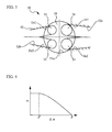
- FIG. 3 is an arrangement view of valves of the engine 50.
- an intake system 10 includes an airflow meter 11, an inter cooler 12, and an intake manifold 13.
- the airflow meter 11 measures an intake air amount GA of the engine 50.
- the inter cooler 12 cools the intake air.
- the intake manifold 13 distributes the intake air to each cylinder 51a of the engine 50.
- An exhaust system 20 includes an exhaust manifold 21 and a catalyst 22.
- the exhaust manifold 21 causes the exhaust gas from each cylinder 51a to join in an exhaust path at the downstream side.
- the catalyst 22 purifies the exhaust gas.
- a supercharger 30 is an exhaust drive-type supercharger, and supercharges the intake air of the engine 50.
- the supercharger 30 includes a compressor portion 31 and a turbine portion 32. The compressor portion 31 is provided in the intake system 10, and the turbine portion 32 is provided in the exhaust system 20.
- the engine 50 is a compression ignition type internal combustion engine (diesel engine). As illustrated in FIG. 2 , the engine 50 includes a cylinder block 51, a cylinder head 52, a piston 53, intake valves 54, exhaust valves 55, a fuel injection valve 56, and an exhaust Variable Valve Timing (VVT) 57.
- VVT Variable Valve Timing
- a cylinder 51a is provided in the cylinder block 51.
- the piston 53 is accommodated in the cylinder 51a.
- the cylinder head 52 is fixed on the top surface of the cylinder block 51.
- a combustion chamber 58 is formed as the space surrounded by the cylinder block 51, the cylinder head 52, and the piston 53.
- An intake port 52a and an exhaust port 52b are formed in the cylinder head 52. Also, the intake valves 54 and the exhaust valves 55 are provided. The intake port 52a introduces the intake air to the combustion chamber 58, and the exhaust port 52b discharges the exhaust gas from the combustion chamber 58. The intake valves 54 open and close the intake port 52a, and the exhaust valves 55 open and close the exhaust port 52b.
- the engine 50 is provided with plural (here, two) intake valves 54 at the combustion chamber 58. Also, plural (here, two) exhaust valves 55 are provided.
- the intake port 52a includes partial intake ports In1 and In2 which are divergent and opened from the upstream side to the combustion chamber 58.
- the exhaust port 52b includes partial exhaust ports Ex1 and Ex2 which are divergent and opened from the downstream side to the combustion chamber 58.
- the two intake valves 54 respectively open and close the partial intake ports In1 and In2
- the two exhaust valves 55 respectively open and close the partial exhaust ports Ex1 and Ex2.
- the fuel injection valve 56 is provided in the cylinder head 52.
- the fuel injection valve 56 injects the fuel directly into the cylinder.
- the exhaust VVT 57 is provided in the cylinder head 52.
- the exhaust VVT 57 is a valve device which is capable of varying the opening timing of at least one exhaust valve 55 (hereinafter referred to as exhaust valve 55A) of the two exhaust valves 55 provided for the combustion chamber 58 with respect to the opening timing of another exhaust valve 55 (hereinafter referred to as exhaust valve 55B) of the two exhaust valves 55.
- the opening timing may be opening and closing timings.
- the exhaust valve 55A corresponds to one exhaust valve
- the exhaust valve 55B corresponds to another exhaust valve.
- a valve device which is capable of varying at least the opening timing of the exhaust valve 55A of the exhaust valves 55A and 55B, is applied to the exhaust VVT 57.
- a valve device which is capable of setting the opening timings of the exhaust valves 55A and 55B independently, may be applied to the exhaust VVT 57.
- a valve device which includes the electromagnetic valves disclosed in Patent Document 1 mentioned above as the exhaust valves 55A and 55B, is applicable to such the above valve device.
- the valve device disclosed in Patent Document 2 can be applied.
- a crank corner sensor 71 for detecting the crank angle and the engine rotational speed NE is provided.
- a valve timing sensor 72 for detecting the valve timings of the exhaust valves 55A and 55B is provided in the exhaust VVT 57.
- a supercharging pressure sensor 73 for detecting the supercharging pressure is provided in the intake system 10.
- An ECU 1 is an electronic control unit according to a control device for an engine.
- the ECU 1 includes a microcomputer equipped with a CPU, a ROM, a RAM , and the like, and input-output circuits 75 and 76.
- the ECU 1 is electrically connected with the airflow meter 11 and the above mentioned sensors 71 to 73.
- the engine load factor KL can be detected by the ECU 1 based on, for example, the output signals from the airflow meter 11.
- the ECU 1 is electrically connected with various sensors and switches such as an accelerator opening sensor 74 for detecting the pressing amount ⁇ of an accelerator pedal 80.
- the accelerator pedal 80 is an acceleration requirement portion to accelerate the engine 50, and the pressing amount ⁇ is a degree of the acceleration requirement.
- the ECU 1 is electrically connected with various controlled objects such as the fuel injection valve 56 and the exhaust VVT 57.
- the ROM stores map data or programs about various kinds of processing performed by the CPU.
- the CPU processes based on a program stored in the ROM and uses a temporary memory area of the RAM if necessary, whereby the ECU 1 functions as various portions such as a control portion, a determination portion, and a detecting portion.
- the function of a control unit as will be described below is achieved.
- the control unit performs the phase control which makes the opening timing of the exhaust valve 55A identical to the opening timing of the exhaust valve 55B, when the engine 50 accelerates.
- the control unit starts performing the phase control, specifically, when the acceleration of the engine 50 is required.
- the acceleration of the engine 50 is required, when the accelerator pedal 80 is pressed.
- the control unit starts performing the phase control, when the acceleration of the engine 50 is required, specifically, when the amount of change ⁇ in pressing level is larger than a predetermined value ⁇ .
- the amount of change ⁇ in pressing level when the acceleration of the engine 50 is required is a degree of the acceleration requirement when the acceleration is required.
- the control unit performs the phase control such that the intake air amount GA becomes a predetermined amount (for example, the maximum amount) when a predetermined time T elapses from the time when the acceleration of the engine 50 is required.
- the predetermined time T can be set shorter than an elapsed time t' which elapses from the time when the acceleration of the engine 50 is required to the time when the intake air amount GA becomes a predetermined amount, in a case of not performing the phase control making the opening timing of the exhaust valve 55A identical to the opening timing of the exhaust valve 55B when the engine 50 accelerates.
- the control unit stops the phase control making the opening timing of the exhaust valve 55A identical to the opening timing of the exhaust valve 55B, when the engine 50 does not accelerate (when the vehicle is in the steady driving state). In contrast, the control unit performs the phase control varying the opening timing of the exhaust valve 55A so as to generate the phase difference ⁇ between the opening timings of the exhaust valves 55A and 55B, when the engine 50 does not accelerate.
- the time when the engine 50 does not accelerate includes the time when the accelerator pedal 80 is not pressed, and further, for example, the time when the engine 50 is brought into the steady driving state in pressing the accelerator pedal 80 (the time when the intake air amount GA is the maximum).
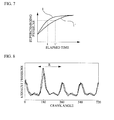
- FIG. 4 is a view of a relationship between the amount of change ⁇ in pressing level and the phase difference ⁇ .
- the vertical axis indicates the phase difference ⁇
- the horizontal axis indicates the amount of change ⁇ in pressing level.
- the control unit adjusts the amount of change in the phase of the exhaust valve 55A such that the phase difference ⁇ is made larger as the amount of change ⁇ in pressing level is smaller than a predetermined value ⁇ .
- the control unit may adjust the amount of change in the phase of the exhaust valve 55A such that the phase difference ⁇ becomes constant.
- control unit performs the advance control making the phase of the exhaust valve 55A identical to the phase of the exhaust valve 55B, when the engine 50 accelerates. Also, the retardation control retarding the phase of the exhaust valve 55A is performed so as to increase the phase difference ⁇ between the exhaust valves 55A and 55B, when the engine 50 does not accelerate.
- FIG. 5 is a view of a change in the valve timing in the acceleration state of the engine 50.
- the vertical axis indicates the valve lift amount, and the horizontal axis indicates the crank angle.
- the control unit performs the advance control making the whole phase of the exhaust valve 55A identical to the whole phase of the exhaust valve 55B without varying the phase of the exhaust valve 55B.
- the control is not limited to this.
- the control unit may perform the phase control varying the phase of the exhaust valve 55B.
- the ECU 1 detects the engine driving state (step S1).
- step S1 for example, the ECU 1 detects, specifically, the engine rotational speed NE, the intake air amount GA, and the pressing amount ⁇ .
- step S2 determines whether or not the flag is ON (step S2).
- the flag is provided for determining whether or not the advance control of the exhaust valve 55A is being performed, and the flag is set to OFF in the initial state. If a negative determination is made in step S2, the ECU 1 calculates the amount of change ⁇ in pressing level (step S3).
- the ECU 1 determines whether or not the amount of change ⁇ in pressing level is more than zero (step S4). If a negative determination is made, it is determined that the engine 50 does not accelerate. In this case, the ECU 1 determines the opening timing of the exhaust valve 55A depending on the detected engine driving state (step S11). The opening timing can be set beforehand by the map data based on the engine driving state (for example, the engine rotational speed NE and the engine load factor KL). This flowchart temporarily finishes after step S11.
- step S4 the ECU 1 sets the flag ON (step S5). After step S5 or after a positive determination is made in step S2, the ECU 1 determines whether or not the amount of change ⁇ in pressing level is larger than the predetermined value ⁇ (step S6). If a negative determination is made, the ECU 1 adjusts the advance amount of the exhaust valve 55A depending on the amount of change ⁇ in pressing level (step S7).
- step S8 After a positive determination is made in step S6 or after step S7, the ECU 1 performs the advance control of the exhaust valve 55A (step S8). After a negative determination is made in step S2, the process proceeds to step S8, and the advance control starts when the acceleration of the engine 50 is required in step S8. Subsequently, the ECU 1 determines whether or not the engine 50 does not accelerate (step S9).
- the engine rotational speed NE is detected, the amount of change ⁇ NE in the engine rotational speed is calculated, and it is determined whether or not the amount of change ⁇ NE is smaller than a predetermined value, whereby it can be determined whether or not the engine 50 does not accelerate.
- the speed of the vehicle is detected, the acceleration is calculated, and it is determined whether or not the acceleration is smaller than a predetermined value, whereby it may be determined whether or not the engine 50 does not accelerate.
- the elapsed time which elapses from the time when the acceleration of the engine 50 is required, is more than the predetermined time t set such that the intake air amount GA becomes the maximum, whereby it may be determined whether or not the engine 50 does not accelerate.
- the predetermined time t can be set beforehand depending on, for example, the amount of change ⁇ in pressing level. Additionally, it can be determined whether or not the engine 50 does not accelerate on the basis of the rotational speed of the supercharger 30.
- step S9 If a negative determination is made in step S9, this flowchart temporarily finishes. In this case, a positive determination is made in step S2 in the next routine. On the other hand, if a positive determination is made in step S9, the ECU 1 set the flag OFF (step S10). In next step S11, the ECU 1 performs the retardation control of the exhaust valve 55A. Next, this flowchart temporarily finishes after step S11.
- the ECU 1 performs the phase control making the opening timing of the exhaust valve 55A identical to the opening timing of the exhaust valve 55B, when the engine 50 accelerates. Specifically, the phase control, which makes the phase of the exhaust valve 55A identical to the phase of the exhaust valve 55B, is performed. Thus, the ECU 1 can emphasize the feeling of the acceleration by use of the exhaust sound when the engine 50 accelerates.
- the ECU 1 can suitably control the exhaust sound of the engine 50 provided with the exhaust VVT 57 in consideration of the acceleration of the engine 50.
- the phase control varying the opening timing of the exhaust valve 55A is performed, for example, so as to generate the phase difference ⁇ between the exhaust valves 55A and 55B when the vehicle is in the steady driving state, thereby suppressing the exhaust sound.
- the ECU 1 performs the advance control making the phase of the exhaust valve 55A identical to the phase of the exhaust valve 55B, when the engine 50 accelerates.
- the blow down pressure of the exhaust is lower as the exhaust valves 55A and 55B are further retarded. Therefore, the ECU 1 can suitably emphasize the exhaust sound by performing the advance control making the phase of the exhaust valve 55A identical to the phase of the exhaust valve 55B.
- the ECU 1 performs the retardation control retarding the phase of the exhaust valve 55A so as to increase the phase difference ⁇ between the exhaust valves 55A and 55B, when the vehicle is in the steady driving state. Therefore, when the vehicle is in the steady driving state, the ECU 1 can reduce the compression ratio of the engine 50 in a consistent manner with the advance control making the phase of the exhaust valve 55A identical to the phase of the exhaust valve 55B. This improves the fuel consumption and the exhaust emission at the same time.
- the ECU 1 adjusts the amount of change in the phase of the exhaust valve 55A depending on the amount of change ⁇ in pressing level, thereby suitably controlling the exhaust sound depending on the degree of the acceleration requirement. Further, the ECU 1 starts performing the phase control making the opening timing of the exhaust valve 55A identical to the opening timing of the exhaust valve 55B when the acceleration of the engine 50 is required, thereby suitably controlling the exhaust sound of the engine 50 in the aspect of timing.
- the ECU 1 performs the phase control making the opening timing of the exhaust valve 55A identical to the opening timing of the exhaust valve 55B when the engine 50 provided with the supercharger 30 accelerates, thereby increasing the exhaust energy. Therefore, the improvement in the supercharging pressure improves the acceleration performance and the exhaust sound level. Accordingly, the feeling of the acceleration can be suitably emphasized.
- FIG. 7 is a view of a change in the supercharging pressure depending on the elapsed time.
- the vertical axis indicates the supercharging pressure
- the horizontal axis indicates the elapsed time elapsing from the time when the acceleration of the engine 50 is required.
- An ECU 1' indicates a case of not performing the phase control making the opening timing of the exhaust valve 55A identical to the opening timing of the exhaust valve 55B at the time when the engine 50 accelerates.
- the ECU 1 can increase the supercharging pressure quickly, as compared with the ECU 1'. Specifically, the ECU 1 can increase the supercharging pressure to achieve the same value in the predetermined time t shorter than the elapsed time t' required for the ECU 1'. Thus, the ECU 1 can more suitably emphasize the feeling of the acceleration.
- the engine may be a spark-ignition type internal combustion engine.
- plural one-exhaust valves or plural another-exhaust valves may be provided.
Landscapes
- Engineering & Computer Science (AREA)
- Chemical & Material Sciences (AREA)
- Combustion & Propulsion (AREA)
- Mechanical Engineering (AREA)
- General Engineering & Computer Science (AREA)
- Output Control And Ontrol Of Special Type Engine (AREA)
- Valve Device For Special Equipments (AREA)
Abstract
Description
- The present invention relates to a control device for an engine, in particular, to a control device for an engine controlling exhaust sound of the engine provided with a valve device which is capable of varying opening and closing timings of one exhaust valve of a plurality of exhaust valves provided for a combustion chamber with respect to opening and closing timings of another exhaust valve of the plurality of exhaust valves.
- There is known an engine provided with a valve device which is capable of varying opening and closing timings of one exhaust valve of a plurality of exhaust valves provided for a combustion chamber with respect to opening and closing timings of another exhaust valve of the plurality of exhaust valves.
Patent Document 1 discloses an internal combustion engine provided with plural electromagnetic valves as exhaust valves in the same cylinder. In this internal combustion engine, the difference between the earliest opening timing of an exhaust valve and the latest opening timing of another exhaust valve is larger as the engine rotational speed is lower, thereby suppressing the exhaust sound. Patent Document 2 discloses a valve device varying valve timings of first and second engine valves which are the same type of engine valves provided for a combustion chamber. -
- [Patent Document 1] Japanese Patent Application Publication No.
2001-241337 - [Patent Document 2] Japanese Patent Application Publication No.
2009-144521 -
FIG. 8 is a view of an example of a change in the exhaust pressure pulsation depending on a crank angle. The vertical axis indicates the exhaust pressure, and the horizontal axis indicates the crank angle. The solid line indicates a case of opening the plural exhaust valves provided for the combustion chamber simultaneously. The broken line indicates a case of opening the plural exhaust valves with different phases thereof. As illustrated inFIG. 8 , the exhaust pressure is reduced during the exhaust valve opening period R in the case of opening the plural exhaust valves with different phases thereof, as compared with the case of opening the plural exhaust valves simultaneously. As a result, the exhaust sound can be suppressed. - This is because the exhaust sound of the first explosion increases in proportion to the blow down pressure when the exhaust valves open, and this is because the blow down pressure increases in proportion to an opening area opened by the exhaust valves. However, the exhaust sound is suppressed when the acceleration is required to a large degree such as when the acceleration is required at full throttle, so that the feeling of acceleration is lost. Thus, it is desirable to suitably control the exhaust sound in consideration of the acceleration of the engine.
- The present invention has been made in view of the above circumstances and has an object to provide a control device for an engine suitably controlling exhaust sound of the engine in consideration of the acceleration of the engine provided with a valve device which is capable of varying opening and closing timings of one exhaust valve of a plurality of exhaust valves provided for a combustion chamber with respect to opening and closing timings of another exhaust valve of the plurality of exhaust valves.
- An aspect of the present invention is a control device for an engine provided with a valve device which is capable of varying opening and closing timings of at least one exhaust valve of a plurality of exhaust valves provided for a combustion chamber with respect to opening and closing timings of another exhaust valve of the plurality of exhaust valves, the control device for the engine including a control unit configured to perform phase control for making a phase of the one exhaust valve identical to a phase of the another exhaust valve when the engine accelerates.
- In the present invention, it is preferable that the control unit is configured to perform advance control for making the phase of the one exhaust valve identical to the phase of the another exhaust valve.
- In the present invention, it is preferable that the control unit is configured to adjust an advance amount of the one exhaust valve depending on a degree of an acceleration requirement of the engine when performing the advance control.
- In the present invention, it is preferable that the control unit is configured to perform retardation control for retarding the phase of the one exhaust valve to increase a phase difference between the one exhaust valve and the another exhaust valve when the engine does not accelerate.
- According to the present invention, it is possible to suitably control exhaust sound of an engine in consideration of the acceleration of the engine provided with a valve device which is capable of varying opening and closing timings of one exhaust valve of a plurality of exhaust valves provided for a combustion chamber with respect to opening and closing timings of another exhaust valve of the plurality of exhaust valves.
-
-
FIG. 1 is a general configuration view of an engine and the vicinity thereof; -
FIG. 2 is a schematic view of the engine; -
FIG. 3 is an arrangement view of valves of the engine; -
FIG. 4 is a view of a relationship between an amount of change in pressing level and a phase difference between opening timings of exhaust valves; -
FIG. 5 is a view of a change in the valve timing in an acceleration state; -
FIG. 6 is a view of a flow chart of the operation of an ECU; -
FIG. 7 is a view of a change in the supercharging pressure depending on the elapsed time; and -
FIG. 8 is a view of an example of a change in the exhaust pressure pulsation. - Embodiments will be described with reference to drawings.
-
FIG. 1 is a general configuration view of anengine 50 and the vicinity thereof.FIG. 2 is a schematic view of theengine 50.FIG. 3 is an arrangement view of valves of theengine 50. Each configuration illustrated inFIG. 1 is mounted on a vehicle. As illustrated inFIG. 1 , anintake system 10 includes an airflow meter 11, aninter cooler 12, and anintake manifold 13. The airflow meter 11 measures an intake air amount GA of theengine 50. Theinter cooler 12 cools the intake air. Theintake manifold 13 distributes the intake air to eachcylinder 51a of theengine 50. - An
exhaust system 20 includes anexhaust manifold 21 and acatalyst 22. Theexhaust manifold 21 causes the exhaust gas from eachcylinder 51a to join in an exhaust path at the downstream side. Thecatalyst 22 purifies the exhaust gas. A supercharger 30 is an exhaust drive-type supercharger, and supercharges the intake air of theengine 50. The supercharger 30 includes a compressor portion 31 and a turbine portion 32. The compressor portion 31 is provided in theintake system 10, and the turbine portion 32 is provided in theexhaust system 20. - The
engine 50 is a compression ignition type internal combustion engine (diesel engine). As illustrated inFIG. 2 , theengine 50 includes acylinder block 51, acylinder head 52, apiston 53,intake valves 54,exhaust valves 55, afuel injection valve 56, and an exhaust Variable Valve Timing (VVT) 57. - A
cylinder 51a is provided in thecylinder block 51. Thepiston 53 is accommodated in thecylinder 51a. Thecylinder head 52 is fixed on the top surface of thecylinder block 51. Acombustion chamber 58 is formed as the space surrounded by thecylinder block 51, thecylinder head 52, and thepiston 53. - An
intake port 52a and anexhaust port 52b are formed in thecylinder head 52. Also, theintake valves 54 and theexhaust valves 55 are provided. Theintake port 52a introduces the intake air to thecombustion chamber 58, and theexhaust port 52b discharges the exhaust gas from thecombustion chamber 58.
Theintake valves 54 open and close theintake port 52a, and theexhaust valves 55 open and close theexhaust port 52b. - As illustrated in
FIG. 3 , specifically, theengine 50 is provided with plural (here, two)intake valves 54 at thecombustion chamber 58. Also, plural (here, two)exhaust valves 55 are provided. In this regard, specifically, theintake port 52a includes partial intake ports In1 and In2 which are divergent and opened from the upstream side to thecombustion chamber 58. Further, theexhaust port 52b includes partial exhaust ports Ex1 and Ex2 which are divergent and opened from the downstream side to thecombustion chamber 58. Also, the twointake valves 54 respectively open and close the partial intake ports In1 and In2, and the twoexhaust valves 55 respectively open and close the partial exhaust ports Ex1 and Ex2. - As illustrated in
FIG. 2 , thefuel injection valve 56 is provided in thecylinder head 52. Thefuel injection valve 56 injects the fuel directly into the cylinder. Also, theexhaust VVT 57 is provided in thecylinder head 52. Theexhaust VVT 57 is a valve device which is capable of varying the opening timing of at least one exhaust valve 55 (hereinafter referred to asexhaust valve 55A) of the twoexhaust valves 55 provided for thecombustion chamber 58 with respect to the opening timing of another exhaust valve 55 (hereinafter referred to asexhaust valve 55B) of the twoexhaust valves 55. In this regard, the opening timing may be opening and closing timings. Theexhaust valve 55A corresponds to one exhaust valve, and theexhaust valve 55B corresponds to another exhaust valve. - In a case of varying the opening timing of the
exhaust valve 55A with respect to the opening timing of theexhaust valve 55B, a valve device, which is capable of varying at least the opening timing of theexhaust valve 55A of theexhaust valves exhaust VVT 57. For example, a valve device, which is capable of setting the opening timings of theexhaust valves exhaust VVT 57. Specifically, for example, a valve device, which includes the electromagnetic valves disclosed inPatent Document 1 mentioned above as theexhaust valves - Various sensors are provided in the
engine 50. Specifically, for example, a crank corner sensor 71 for detecting the crank angle and the engine rotational speed NE is provided. Also, avalve timing sensor 72 for detecting the valve timings of theexhaust valves exhaust VVT 57. A superchargingpressure sensor 73 for detecting the supercharging pressure is provided in theintake system 10. - An
ECU 1 is an electronic control unit according to a control device for an engine. TheECU 1 includes a microcomputer equipped with a CPU, a ROM, a RAM , and the like, and input-output circuits 75 and 76. TheECU 1 is electrically connected with the airflow meter 11 and the above mentioned sensors 71 to 73. The engine load factor KL can be detected by theECU 1 based on, for example, the output signals from the airflow meter 11. - Further, the
ECU 1 is electrically connected with various sensors and switches such as anaccelerator opening sensor 74 for detecting the pressing amount α of anaccelerator pedal 80. Theaccelerator pedal 80 is an acceleration requirement portion to accelerate theengine 50, and the pressing amount α is a degree of the acceleration requirement. TheECU 1 is electrically connected with various controlled objects such as thefuel injection valve 56 and theexhaust VVT 57. - The ROM stores map data or programs about various kinds of processing performed by the CPU. The CPU processes based on a program stored in the ROM and uses a temporary memory area of the RAM if necessary, whereby the
ECU 1 functions as various portions such as a control portion, a determination portion, and a detecting portion. For example, in theECU 1, the function of a control unit as will be described below is achieved. - The control unit performs the phase control which makes the opening timing of the
exhaust valve 55A identical to the opening timing of theexhaust valve 55B, when theengine 50 accelerates. In this regard, the control unit starts performing the phase control, specifically, when the acceleration of theengine 50 is required. For example, the acceleration of theengine 50 is required, when theaccelerator pedal 80 is pressed. The control unit starts performing the phase control, when the acceleration of theengine 50 is required, specifically, when the amount of change Δα in pressing level is larger than a predetermined value β. The amount of change Δα in pressing level when the acceleration of theengine 50 is required is a degree of the acceleration requirement when the acceleration is required. - Also, the control unit performs the phase control such that the intake air amount GA becomes a predetermined amount (for example, the maximum amount) when a predetermined time T elapses from the time when the acceleration of the
engine 50 is required. The predetermined time T can be set shorter than an elapsed time t' which elapses from the time when the acceleration of theengine 50 is required to the time when the intake air amount GA becomes a predetermined amount, in a case of not performing the phase control making the opening timing of theexhaust valve 55A identical to the opening timing of theexhaust valve 55B when theengine 50 accelerates. - The control unit stops the phase control making the opening timing of the
exhaust valve 55A identical to the opening timing of theexhaust valve 55B, when theengine 50 does not accelerate (when the vehicle is in the steady driving state). In contrast, the control unit performs the phase control varying the opening timing of theexhaust valve 55A so as to generate the phase difference γ between the opening timings of theexhaust valves engine 50 does not accelerate. The time when theengine 50 does not accelerate includes the time when theaccelerator pedal 80 is not pressed, and further, for example, the time when theengine 50 is brought into the steady driving state in pressing the accelerator pedal 80 (the time when the intake air amount GA is the maximum). - When performing the phase control at the time when the
engine 50 accelerates, the control unit adjusts the amount of change in the phase of theexhaust valve 55A depending on the amount of change Δα in pressing level.FIG. 4 is a view of a relationship between the amount of change Δα in pressing level and the phase difference γ. The vertical axis indicates the phase difference γ, and the horizontal axis indicates the amount of change Δα in pressing level. - As illustrated in
FIG. 4 , the control unit adjusts the amount of change in the phase of theexhaust valve 55A such that the phase difference γ is made larger as the amount of change Δα in pressing level is smaller than a predetermined value β. When the amount of change Δα in pressing level is smaller than a predetermined value β' smaller than the predetermined value β, the control unit may adjust the amount of change in the phase of theexhaust valve 55A such that the phase difference γ becomes constant. - Specifically, the control unit performs the advance control making the phase of the
exhaust valve 55A identical to the phase of theexhaust valve 55B, when theengine 50 accelerates. Also, the retardation control retarding the phase of theexhaust valve 55A is performed so as to increase the phase difference γ between theexhaust valves engine 50 does not accelerate. -
FIG. 5 is a view of a change in the valve timing in the acceleration state of theengine 50. The vertical axis indicates the valve lift amount, and the horizontal axis indicates the crank angle. Specifically, the control unit performs the advance control making the whole phase of theexhaust valve 55A identical to the whole phase of theexhaust valve 55B without varying the phase of theexhaust valve 55B. However, the control is not limited to this. For example, the control unit may perform the phase control varying the phase of theexhaust valve 55B. - Next, a description will be given of the operation of the
ECU 1 with reference to a flowchart illustrated inFIG. 6 . TheECU 1 detects the engine driving state (step S1). In step S1, for example, theECU 1 detects, specifically, the engine rotational speed NE, the intake air amount GA, and the pressing amount α. Subsequently, theECU 1 determines whether or not the flag is ON (step S2). The flag is provided for determining whether or not the advance control of theexhaust valve 55A is being performed, and the flag is set to OFF in the initial state. If a negative determination is made in step S2, theECU 1 calculates the amount of change Δα in pressing level (step S3). - Subsequently, the
ECU 1 determines whether or not the amount of change Δα in pressing level is more than zero (step S4). If a negative determination is made, it is determined that theengine 50 does not accelerate. In this case, theECU 1 determines the opening timing of theexhaust valve 55A depending on the detected engine driving state (step S11). The opening timing can be set beforehand by the map data based on the engine driving state (for example, the engine rotational speed NE and the engine load factor KL). This flowchart temporarily finishes after step S11. - On the other hand, if a positive determination is made in step S4, the
ECU 1 sets the flag ON (step S5). After step S5 or after a positive determination is made in step S2, theECU 1 determines whether or not the amount of change Δα in pressing level is larger than the predetermined value β (step S6). If a negative determination is made, theECU 1 adjusts the advance amount of theexhaust valve 55A depending on the amount of change Δα in pressing level (step S7). - After a positive determination is made in step S6 or after step S7, the
ECU 1 performs the advance control of theexhaust valve 55A (step S8). After a negative determination is made in step S2, the process proceeds to step S8, and the advance control starts when the acceleration of theengine 50 is required in step S8. Subsequently, theECU 1 determines whether or not theengine 50 does not accelerate (step S9). - For example, the engine rotational speed NE is detected, the amount of change ΔNE in the engine rotational speed is calculated, and it is determined whether or not the amount of change ΔNE is smaller than a predetermined value, whereby it can be determined whether or not the
engine 50 does not accelerate. Also, for example, the speed of the vehicle is detected, the acceleration is calculated, and it is determined whether or not the acceleration is smaller than a predetermined value, whereby it may be determined whether or not theengine 50 does not accelerate. - Moreover, for example, it is determined whether or not the elapsed time, which elapses from the time when the acceleration of the
engine 50 is required, is more than the predetermined time t set such that the intake air amount GA becomes the maximum, whereby it may be determined whether or not theengine 50 does not accelerate. The predetermined time t can be set beforehand depending on, for example, the amount of change Δα in pressing level. Additionally, it can be determined whether or not theengine 50 does not accelerate on the basis of the rotational speed of the supercharger 30. - If a negative determination is made in step S9, this flowchart temporarily finishes. In this case, a positive determination is made in step S2 in the next routine. On the other hand, if a positive determination is made in step S9, the
ECU 1 set the flag OFF (step S10). In next step S11, theECU 1 performs the retardation control of theexhaust valve 55A. Next, this flowchart temporarily finishes after step S11. - Next, the effect of the
ECU 1 will be described. TheECU 1 performs the phase control making the opening timing of theexhaust valve 55A identical to the opening timing of theexhaust valve 55B, when theengine 50 accelerates. Specifically, the phase control, which makes the phase of theexhaust valve 55A identical to the phase of theexhaust valve 55B, is performed. Thus, theECU 1 can emphasize the feeling of the acceleration by use of the exhaust sound when theengine 50 accelerates. - Accordingly, the
ECU 1 can suitably control the exhaust sound of theengine 50 provided with theexhaust VVT 57 in consideration of the acceleration of theengine 50. Specifically, the phase control varying the opening timing of theexhaust valve 55A is performed, for example, so as to generate the phase difference γ between theexhaust valves - In this regard, the
ECU 1 performs the advance control making the phase of theexhaust valve 55A identical to the phase of theexhaust valve 55B, when theengine 50 accelerates. Herein, in general, the blow down pressure of the exhaust is lower as theexhaust valves ECU 1 can suitably emphasize the exhaust sound by performing the advance control making the phase of theexhaust valve 55A identical to the phase of theexhaust valve 55B. - Also, the
ECU 1 performs the retardation control retarding the phase of theexhaust valve 55A so as to increase the phase difference γ between theexhaust valves ECU 1 can reduce the compression ratio of theengine 50 in a consistent manner with the advance control making the phase of theexhaust valve 55A identical to the phase of theexhaust valve 55B. This improves the fuel consumption and the exhaust emission at the same time. - Also, the
ECU 1 adjusts the amount of change in the phase of theexhaust valve 55A depending on the amount of change Δα in pressing level, thereby suitably controlling the exhaust sound depending on the degree of the acceleration requirement. Further, theECU 1 starts performing the phase control making the opening timing of theexhaust valve 55A identical to the opening timing of theexhaust valve 55B when the acceleration of theengine 50 is required, thereby suitably controlling the exhaust sound of theengine 50 in the aspect of timing. - Furthermore, the
ECU 1 performs the phase control making the opening timing of theexhaust valve 55A identical to the opening timing of theexhaust valve 55B when theengine 50 provided with the supercharger 30 accelerates, thereby increasing the exhaust energy. Therefore, the improvement in the supercharging pressure improves the acceleration performance and the exhaust sound level. Accordingly, the feeling of the acceleration can be suitably emphasized. - Moreover, when the
engine 50 provided with the supercharger 30 accelerates, theECU 1 performs the phase control such that the intake air amount GA achieves the predetermined amount in the predetermined time t, thereby quickly increasing the supercharging pressure.FIG. 7 is a view of a change in the supercharging pressure depending on the elapsed time. The vertical axis indicates the supercharging pressure, and the horizontal axis indicates the elapsed time elapsing from the time when the acceleration of theengine 50 is required. An ECU 1' indicates a case of not performing the phase control making the opening timing of theexhaust valve 55A identical to the opening timing of theexhaust valve 55B at the time when theengine 50 accelerates. - As illustrated in
FIG. 7 , theECU 1 can increase the supercharging pressure quickly, as compared with the ECU 1'. Specifically, theECU 1 can increase the supercharging pressure to achieve the same value in the predetermined time t shorter than the elapsed time t' required for the ECU 1'. Thus, theECU 1 can more suitably emphasize the feeling of the acceleration. - While the exemplary embodiments of the present invention have been illustrated in detail, the present invention is not limited to the above-mentioned embodiments, and other embodiments, variations and modifications may be made without departing from the scope of the present invention.
For example, the engine may be a spark-ignition type internal combustion engine. Also, for example, plural one-exhaust valves or plural another-exhaust valves may be provided. -
- ECU
- 1, 1'
- supercharger
- 30
- engine
- 50
- exhaust valve
- 55, 55A, 55B
- fuel injection valve
- 56
- exhaust VVT
- 57
- combustion chamber
- 58
- accelerator pedal
- 80
Claims (4)
- A control device for an engine provided with a valve device which is capable of varying opening and closing timings of at least one exhaust valve of a plurality of exhaust valves provided for a combustion chamber with respect to opening and closing timings of another exhaust valve of the plurality of exhaust valves, the control device for the engine comprising
a control unit configured to perform phase control for making a phase of the one exhaust valve identical to a phase of the another exhaust valve when the engine accelerates. - The control device for the engine of claim 1, wherein the control unit is configured to perform advance control for making the phase of the one exhaust valve identical to the phase of the another exhaust valve.
- The control device for the engine of claim 2, wherein the control unit is configured to adjust an advance amount of the one exhaust valve depending on a degree of an acceleration requirement of the engine when performing the advance control.
- The control device for the engine of claim 2 or 3, wherein the control unit is configured to perform retardation control for retarding the phase of the one exhaust valve to increase a phase difference between the one exhaust valve and the another exhaust valve when the engine does not accelerate.
Applications Claiming Priority (1)
| Application Number | Priority Date | Filing Date | Title |
|---|---|---|---|
| PCT/JP2010/069590 WO2012060000A1 (en) | 2010-11-04 | 2010-11-04 | Control device for engine |
Publications (3)
| Publication Number | Publication Date |
|---|---|
| EP2636874A1 true EP2636874A1 (en) | 2013-09-11 |
| EP2636874A4 EP2636874A4 (en) | 2015-03-04 |
| EP2636874B1 EP2636874B1 (en) | 2017-04-19 |
Family
ID=46024130
Family Applications (1)
| Application Number | Title | Priority Date | Filing Date |
|---|---|---|---|
| EP10859257.7A Not-in-force EP2636874B1 (en) | 2010-11-04 | 2010-11-04 | Control device for engine |
Country Status (5)
| Country | Link |
|---|---|
| US (1) | US8820296B2 (en) |
| EP (1) | EP2636874B1 (en) |
| JP (1) | JP5472481B2 (en) |
| CN (1) | CN103189622B (en) |
| WO (1) | WO2012060000A1 (en) |
Families Citing this family (2)
| Publication number | Priority date | Publication date | Assignee | Title |
|---|---|---|---|---|
| JP6460412B2 (en) * | 2016-03-31 | 2019-01-30 | マツダ株式会社 | Engine control device |
| JP6554239B2 (en) * | 2016-09-28 | 2019-07-31 | 日立オートモティブシステムズ株式会社 | Vehicle control device |
Family Cites Families (13)
| Publication number | Priority date | Publication date | Assignee | Title |
|---|---|---|---|---|
| DE3506106A1 (en) * | 1984-02-22 | 1985-08-22 | Audi AG, 8070 Ingolstadt | Method for controlling the power output of an exhaust turbocharger supplying a valve-timed internal combustion engine |
| DE3714192A1 (en) * | 1987-04-29 | 1988-11-10 | Bosch Gmbh Robert | Method of controlling an exhaust turbocharger |
| JPH02115512A (en) | 1988-10-25 | 1990-04-27 | Mazda Motor Corp | Intake/exhaust device for automobile engine |
| JP2000064859A (en) * | 1998-08-20 | 2000-02-29 | Daihatsu Motor Co Ltd | Uniflow type two-cycle engine |
| JP4218169B2 (en) | 2000-02-28 | 2009-02-04 | トヨタ自動車株式会社 | Internal combustion engine having an electromagnetically driven valve |
| US6405693B2 (en) * | 2000-02-28 | 2002-06-18 | Toyota Jidosha Kabushiki Kaisha | Internal combustion engine and method for controlling valve of internal combustion engine |
| FR2844546B1 (en) * | 2002-09-16 | 2006-06-02 | Renault Sa | SUPER-POWERED MOTOR WITH LOW-SPEED OPTIMIZED TORQUE |
| JP2006083818A (en) * | 2004-09-17 | 2006-03-30 | Toyota Motor Corp | Engine sound enhancement device |
| US7134407B1 (en) * | 2005-05-23 | 2006-11-14 | Nelson Gregory J | V-quad engine and method of constructing same |
| JP2009036169A (en) * | 2007-08-03 | 2009-02-19 | Toyota Motor Corp | Internal combustion engine |
| DE102007042053A1 (en) * | 2007-09-05 | 2009-03-12 | Mahle International Gmbh | piston engine |
| JP4747158B2 (en) | 2007-12-11 | 2011-08-17 | 本田技研工業株式会社 | Valve operating apparatus provided with phase control means |
| JP5299103B2 (en) * | 2009-06-12 | 2013-09-25 | マツダ株式会社 | Engine valve timing control device |
-
2010
- 2010-11-04 EP EP10859257.7A patent/EP2636874B1/en not_active Not-in-force
- 2010-11-04 WO PCT/JP2010/069590 patent/WO2012060000A1/en not_active Ceased
- 2010-11-04 CN CN201080069949.7A patent/CN103189622B/en not_active Expired - Fee Related
- 2010-11-04 JP JP2012541686A patent/JP5472481B2/en not_active Expired - Fee Related
- 2010-11-04 US US13/879,276 patent/US8820296B2/en not_active Expired - Fee Related
Also Published As
| Publication number | Publication date |
|---|---|
| EP2636874A4 (en) | 2015-03-04 |
| JPWO2012060000A1 (en) | 2014-05-12 |
| US20130220273A1 (en) | 2013-08-29 |
| US8820296B2 (en) | 2014-09-02 |
| CN103189622A (en) | 2013-07-03 |
| CN103189622B (en) | 2015-04-22 |
| EP2636874B1 (en) | 2017-04-19 |
| JP5472481B2 (en) | 2014-04-16 |
| WO2012060000A1 (en) | 2012-05-10 |
Similar Documents
| Publication | Publication Date | Title |
|---|---|---|
| US8256217B2 (en) | System and method for determining acceleration of an internal combustion engine | |
| JP6208097B2 (en) | Internal combustion engine equipment | |
| US9964055B2 (en) | Control device and control method of internal combustion engine | |
| EP3144509B1 (en) | Control apparatus for an internal combustion engine with variable valve actuation | |
| US11187166B2 (en) | Internal combustion engine and method of controlling same | |
| JP4893514B2 (en) | Control device for an internal combustion engine with a supercharger | |
| US10408141B2 (en) | Lean-burn engine | |
| US9303553B2 (en) | Turbo speed control for mode transitions in a dual turbo system | |
| US8820296B2 (en) | Control device for engine | |
| US10094301B2 (en) | Internal combustion engine controller | |
| JP2019039405A (en) | Engine control device | |
| US9303569B2 (en) | Control device for internal combustion engine | |
| JP5949450B2 (en) | Control device for internal combustion engine | |
| JP5338709B2 (en) | Control device for internal combustion engine | |
| US20190293002A1 (en) | Control device for engine | |
| JP6406185B2 (en) | Engine control device | |
| JP6406300B2 (en) | Engine control device | |
| JP5467928B2 (en) | Ignition timing correction control method for internal combustion engine | |
| JP2010019085A (en) | Intake control device for engine | |
| JP2017025891A (en) | Control device of engine |
Legal Events
| Date | Code | Title | Description |
|---|---|---|---|
| PUAI | Public reference made under article 153(3) epc to a published international application that has entered the european phase |
Free format text: ORIGINAL CODE: 0009012 |
|
| 17P | Request for examination filed |
Effective date: 20130503 |
|
| AK | Designated contracting states |
Kind code of ref document: A1 Designated state(s): AL AT BE BG CH CY CZ DE DK EE ES FI FR GB GR HR HU IE IS IT LI LT LU LV MC MK MT NL NO PL PT RO RS SE SI SK SM TR |
|
| DAX | Request for extension of the european patent (deleted) | ||
| A4 | Supplementary search report drawn up and despatched |
Effective date: 20150202 |
|
| RIC1 | Information provided on ipc code assigned before grant |
Ipc: F02D 13/02 20060101AFI20150127BHEP Ipc: F02D 45/00 20060101ALI20150127BHEP |
|
| 17Q | First examination report despatched |
Effective date: 20160307 |
|
| RIC1 | Information provided on ipc code assigned before grant |
Ipc: F02D 45/00 20060101ALI20161005BHEP Ipc: F02D 13/02 20060101AFI20161005BHEP Ipc: F02D 41/10 20060101ALI20161005BHEP |
|
| GRAP | Despatch of communication of intention to grant a patent |
Free format text: ORIGINAL CODE: EPIDOSNIGR1 |
|
| STAA | Information on the status of an ep patent application or granted ep patent |
Free format text: STATUS: GRANT OF PATENT IS INTENDED |
|
| INTG | Intention to grant announced |
Effective date: 20161124 |
|
| INTG | Intention to grant announced |
Effective date: 20161130 |
|
| GRAS | Grant fee paid |
Free format text: ORIGINAL CODE: EPIDOSNIGR3 |
|
| GRAA | (expected) grant |
Free format text: ORIGINAL CODE: 0009210 |
|
| STAA | Information on the status of an ep patent application or granted ep patent |
Free format text: STATUS: THE PATENT HAS BEEN GRANTED |
|
| AK | Designated contracting states |
Kind code of ref document: B1 Designated state(s): AL AT BE BG CH CY CZ DE DK EE ES FI FR GB GR HR HU IE IS IT LI LT LU LV MC MK MT NL NO PL PT RO RS SE SI SK SM TR |
|
| REG | Reference to a national code |
Ref country code: GB Ref legal event code: FG4D |
|
| REG | Reference to a national code |
Ref country code: CH Ref legal event code: EP |
|
| REG | Reference to a national code |
Ref country code: AT Ref legal event code: REF Ref document number: 886215 Country of ref document: AT Kind code of ref document: T Effective date: 20170515 |
|
| REG | Reference to a national code |
Ref country code: IE Ref legal event code: FG4D |
|
| REG | Reference to a national code |
Ref country code: DE Ref legal event code: R096 Ref document number: 602010041764 Country of ref document: DE |
|
| REG | Reference to a national code |
Ref country code: DE Ref legal event code: R084 Ref document number: 602010041764 Country of ref document: DE |
|
| REG | Reference to a national code |
Ref country code: NL Ref legal event code: MP Effective date: 20170419 |
|
| REG | Reference to a national code |
Ref country code: LT Ref legal event code: MG4D |
|
| REG | Reference to a national code |
Ref country code: AT Ref legal event code: MK05 Ref document number: 886215 Country of ref document: AT Kind code of ref document: T Effective date: 20170419 |
|
| PG25 | Lapsed in a contracting state [announced via postgrant information from national office to epo] |
Ref country code: NL Free format text: LAPSE BECAUSE OF FAILURE TO SUBMIT A TRANSLATION OF THE DESCRIPTION OR TO PAY THE FEE WITHIN THE PRESCRIBED TIME-LIMIT Effective date: 20170419 |
|
| PG25 | Lapsed in a contracting state [announced via postgrant information from national office to epo] |
Ref country code: FI Free format text: LAPSE BECAUSE OF FAILURE TO SUBMIT A TRANSLATION OF THE DESCRIPTION OR TO PAY THE FEE WITHIN THE PRESCRIBED TIME-LIMIT Effective date: 20170419 Ref country code: ES Free format text: LAPSE BECAUSE OF FAILURE TO SUBMIT A TRANSLATION OF THE DESCRIPTION OR TO PAY THE FEE WITHIN THE PRESCRIBED TIME-LIMIT Effective date: 20170419 Ref country code: LT Free format text: LAPSE BECAUSE OF FAILURE TO SUBMIT A TRANSLATION OF THE DESCRIPTION OR TO PAY THE FEE WITHIN THE PRESCRIBED TIME-LIMIT Effective date: 20170419 Ref country code: AT Free format text: LAPSE BECAUSE OF FAILURE TO SUBMIT A TRANSLATION OF THE DESCRIPTION OR TO PAY THE FEE WITHIN THE PRESCRIBED TIME-LIMIT Effective date: 20170419 Ref country code: NO Free format text: LAPSE BECAUSE OF FAILURE TO SUBMIT A TRANSLATION OF THE DESCRIPTION OR TO PAY THE FEE WITHIN THE PRESCRIBED TIME-LIMIT Effective date: 20170719 Ref country code: HR Free format text: LAPSE BECAUSE OF FAILURE TO SUBMIT A TRANSLATION OF THE DESCRIPTION OR TO PAY THE FEE WITHIN THE PRESCRIBED TIME-LIMIT Effective date: 20170419 Ref country code: GR Free format text: LAPSE BECAUSE OF FAILURE TO SUBMIT A TRANSLATION OF THE DESCRIPTION OR TO PAY THE FEE WITHIN THE PRESCRIBED TIME-LIMIT Effective date: 20170720 |
|
| PG25 | Lapsed in a contracting state [announced via postgrant information from national office to epo] |
Ref country code: BG Free format text: LAPSE BECAUSE OF FAILURE TO SUBMIT A TRANSLATION OF THE DESCRIPTION OR TO PAY THE FEE WITHIN THE PRESCRIBED TIME-LIMIT Effective date: 20170719 Ref country code: RS Free format text: LAPSE BECAUSE OF FAILURE TO SUBMIT A TRANSLATION OF THE DESCRIPTION OR TO PAY THE FEE WITHIN THE PRESCRIBED TIME-LIMIT Effective date: 20170419 Ref country code: LV Free format text: LAPSE BECAUSE OF FAILURE TO SUBMIT A TRANSLATION OF THE DESCRIPTION OR TO PAY THE FEE WITHIN THE PRESCRIBED TIME-LIMIT Effective date: 20170419 Ref country code: SE Free format text: LAPSE BECAUSE OF FAILURE TO SUBMIT A TRANSLATION OF THE DESCRIPTION OR TO PAY THE FEE WITHIN THE PRESCRIBED TIME-LIMIT Effective date: 20170419 Ref country code: IS Free format text: LAPSE BECAUSE OF FAILURE TO SUBMIT A TRANSLATION OF THE DESCRIPTION OR TO PAY THE FEE WITHIN THE PRESCRIBED TIME-LIMIT Effective date: 20170819 Ref country code: PL Free format text: LAPSE BECAUSE OF FAILURE TO SUBMIT A TRANSLATION OF THE DESCRIPTION OR TO PAY THE FEE WITHIN THE PRESCRIBED TIME-LIMIT Effective date: 20170419 |
|
| REG | Reference to a national code |
Ref country code: DE Ref legal event code: R097 Ref document number: 602010041764 Country of ref document: DE |
|
| PG25 | Lapsed in a contracting state [announced via postgrant information from national office to epo] |
Ref country code: SK Free format text: LAPSE BECAUSE OF FAILURE TO SUBMIT A TRANSLATION OF THE DESCRIPTION OR TO PAY THE FEE WITHIN THE PRESCRIBED TIME-LIMIT Effective date: 20170419 Ref country code: CZ Free format text: LAPSE BECAUSE OF FAILURE TO SUBMIT A TRANSLATION OF THE DESCRIPTION OR TO PAY THE FEE WITHIN THE PRESCRIBED TIME-LIMIT Effective date: 20170419 Ref country code: DK Free format text: LAPSE BECAUSE OF FAILURE TO SUBMIT A TRANSLATION OF THE DESCRIPTION OR TO PAY THE FEE WITHIN THE PRESCRIBED TIME-LIMIT Effective date: 20170419 Ref country code: RO Free format text: LAPSE BECAUSE OF FAILURE TO SUBMIT A TRANSLATION OF THE DESCRIPTION OR TO PAY THE FEE WITHIN THE PRESCRIBED TIME-LIMIT Effective date: 20170419 Ref country code: EE Free format text: LAPSE BECAUSE OF FAILURE TO SUBMIT A TRANSLATION OF THE DESCRIPTION OR TO PAY THE FEE WITHIN THE PRESCRIBED TIME-LIMIT Effective date: 20170419 |
|
| PLBE | No opposition filed within time limit |
Free format text: ORIGINAL CODE: 0009261 |
|
| STAA | Information on the status of an ep patent application or granted ep patent |
Free format text: STATUS: NO OPPOSITION FILED WITHIN TIME LIMIT |
|
| PG25 | Lapsed in a contracting state [announced via postgrant information from national office to epo] |
Ref country code: SM Free format text: LAPSE BECAUSE OF FAILURE TO SUBMIT A TRANSLATION OF THE DESCRIPTION OR TO PAY THE FEE WITHIN THE PRESCRIBED TIME-LIMIT Effective date: 20170419 Ref country code: IT Free format text: LAPSE BECAUSE OF FAILURE TO SUBMIT A TRANSLATION OF THE DESCRIPTION OR TO PAY THE FEE WITHIN THE PRESCRIBED TIME-LIMIT Effective date: 20170419 |
|
| 26N | No opposition filed |
Effective date: 20180122 |
|
| PG25 | Lapsed in a contracting state [announced via postgrant information from national office to epo] |
Ref country code: SI Free format text: LAPSE BECAUSE OF FAILURE TO SUBMIT A TRANSLATION OF THE DESCRIPTION OR TO PAY THE FEE WITHIN THE PRESCRIBED TIME-LIMIT Effective date: 20170419 |
|
| PG25 | Lapsed in a contracting state [announced via postgrant information from national office to epo] |
Ref country code: MC Free format text: LAPSE BECAUSE OF FAILURE TO SUBMIT A TRANSLATION OF THE DESCRIPTION OR TO PAY THE FEE WITHIN THE PRESCRIBED TIME-LIMIT Effective date: 20170419 |
|
| GBPC | Gb: european patent ceased through non-payment of renewal fee |
Effective date: 20171104 |
|
| PG25 | Lapsed in a contracting state [announced via postgrant information from national office to epo] |
Ref country code: LI Free format text: LAPSE BECAUSE OF NON-PAYMENT OF DUE FEES Effective date: 20171130 Ref country code: CH Free format text: LAPSE BECAUSE OF NON-PAYMENT OF DUE FEES Effective date: 20171130 |
|
| PG25 | Lapsed in a contracting state [announced via postgrant information from national office to epo] |
Ref country code: LU Free format text: LAPSE BECAUSE OF NON-PAYMENT OF DUE FEES Effective date: 20171104 |
|
| REG | Reference to a national code |
Ref country code: FR Ref legal event code: ST Effective date: 20180731 Ref country code: BE Ref legal event code: MM Effective date: 20171130 |
|
| REG | Reference to a national code |
Ref country code: IE Ref legal event code: MM4A |
|
| PG25 | Lapsed in a contracting state [announced via postgrant information from national office to epo] |
Ref country code: MT Free format text: LAPSE BECAUSE OF NON-PAYMENT OF DUE FEES Effective date: 20171104 |
|
| PG25 | Lapsed in a contracting state [announced via postgrant information from national office to epo] |
Ref country code: FR Free format text: LAPSE BECAUSE OF NON-PAYMENT OF DUE FEES Effective date: 20171130 Ref country code: IE Free format text: LAPSE BECAUSE OF NON-PAYMENT OF DUE FEES Effective date: 20171104 |
|
| PG25 | Lapsed in a contracting state [announced via postgrant information from national office to epo] |
Ref country code: BE Free format text: LAPSE BECAUSE OF NON-PAYMENT OF DUE FEES Effective date: 20171130 Ref country code: GB Free format text: LAPSE BECAUSE OF NON-PAYMENT OF DUE FEES Effective date: 20171104 |
|
| PG25 | Lapsed in a contracting state [announced via postgrant information from national office to epo] |
Ref country code: HU Free format text: LAPSE BECAUSE OF FAILURE TO SUBMIT A TRANSLATION OF THE DESCRIPTION OR TO PAY THE FEE WITHIN THE PRESCRIBED TIME-LIMIT; INVALID AB INITIO Effective date: 20101104 |
|
| PG25 | Lapsed in a contracting state [announced via postgrant information from national office to epo] |
Ref country code: CY Free format text: LAPSE BECAUSE OF NON-PAYMENT OF DUE FEES Effective date: 20170419 |
|
| PG25 | Lapsed in a contracting state [announced via postgrant information from national office to epo] |
Ref country code: MK Free format text: LAPSE BECAUSE OF FAILURE TO SUBMIT A TRANSLATION OF THE DESCRIPTION OR TO PAY THE FEE WITHIN THE PRESCRIBED TIME-LIMIT Effective date: 20170419 |
|
| PG25 | Lapsed in a contracting state [announced via postgrant information from national office to epo] |
Ref country code: TR Free format text: LAPSE BECAUSE OF FAILURE TO SUBMIT A TRANSLATION OF THE DESCRIPTION OR TO PAY THE FEE WITHIN THE PRESCRIBED TIME-LIMIT Effective date: 20170419 |
|
| PG25 | Lapsed in a contracting state [announced via postgrant information from national office to epo] |
Ref country code: PT Free format text: LAPSE BECAUSE OF FAILURE TO SUBMIT A TRANSLATION OF THE DESCRIPTION OR TO PAY THE FEE WITHIN THE PRESCRIBED TIME-LIMIT Effective date: 20170419 |
|
| PG25 | Lapsed in a contracting state [announced via postgrant information from national office to epo] |
Ref country code: AL Free format text: LAPSE BECAUSE OF FAILURE TO SUBMIT A TRANSLATION OF THE DESCRIPTION OR TO PAY THE FEE WITHIN THE PRESCRIBED TIME-LIMIT Effective date: 20170419 |
|
| PGFP | Annual fee paid to national office [announced via postgrant information from national office to epo] |
Ref country code: DE Payment date: 20210929 Year of fee payment: 12 |
|
| REG | Reference to a national code |
Ref country code: DE Ref legal event code: R119 Ref document number: 602010041764 Country of ref document: DE |
|
| PG25 | Lapsed in a contracting state [announced via postgrant information from national office to epo] |
Ref country code: DE Free format text: LAPSE BECAUSE OF NON-PAYMENT OF DUE FEES Effective date: 20230601 |