EP2636847A2 - Apparatus and system for directing hot gas - Google Patents
Apparatus and system for directing hot gas Download PDFInfo
- Publication number
- EP2636847A2 EP2636847A2 EP13157969.0A EP13157969A EP2636847A2 EP 2636847 A2 EP2636847 A2 EP 2636847A2 EP 13157969 A EP13157969 A EP 13157969A EP 2636847 A2 EP2636847 A2 EP 2636847A2
- Authority
- EP
- European Patent Office
- Prior art keywords
- aft
- aft frame
- exit
- transition piece
- frame
- Prior art date
- Legal status (The legal status is an assumption and is not a legal conclusion. Google has not performed a legal analysis and makes no representation as to the accuracy of the status listed.)
- Withdrawn
Links
- 230000007704 transition Effects 0.000 claims abstract description 45
- 238000001816 cooling Methods 0.000 claims description 22
- 230000037406 food intake Effects 0.000 claims description 9
- 230000000694 effects Effects 0.000 claims description 7
- 230000003993 interaction Effects 0.000 claims description 5
- 239000007789 gas Substances 0.000 description 25
- 238000000034 method Methods 0.000 description 5
- 239000000567 combustion gas Substances 0.000 description 3
- 238000005336 cracking Methods 0.000 description 3
- 239000000446 fuel Substances 0.000 description 3
- 239000012720 thermal barrier coating Substances 0.000 description 3
- 238000002485 combustion reaction Methods 0.000 description 2
- 238000013400 design of experiment Methods 0.000 description 2
- 238000011144 upstream manufacturing Methods 0.000 description 2
- 230000015556 catabolic process Effects 0.000 description 1
- 230000009429 distress Effects 0.000 description 1
- 238000009760 electrical discharge machining Methods 0.000 description 1
- 239000012530 fluid Substances 0.000 description 1
- 239000011888 foil Substances 0.000 description 1
- 238000004519 manufacturing process Methods 0.000 description 1
- 239000002184 metal Substances 0.000 description 1
- 230000008569 process Effects 0.000 description 1
- 238000010926 purge Methods 0.000 description 1
- 230000003134 recirculating effect Effects 0.000 description 1
- 230000008439 repair process Effects 0.000 description 1
- 239000013598 vector Substances 0.000 description 1
Images




Classifications
-
- F—MECHANICAL ENGINEERING; LIGHTING; HEATING; WEAPONS; BLASTING
- F01—MACHINES OR ENGINES IN GENERAL; ENGINE PLANTS IN GENERAL; STEAM ENGINES
- F01D—NON-POSITIVE DISPLACEMENT MACHINES OR ENGINES, e.g. STEAM TURBINES
- F01D9/00—Stators
- F01D9/02—Nozzles; Nozzle boxes; Stator blades; Guide conduits, e.g. individual nozzles
- F01D9/023—Transition ducts between combustor cans and first stage of the turbine in gas-turbine engines; their cooling or sealings
-
- F—MECHANICAL ENGINEERING; LIGHTING; HEATING; WEAPONS; BLASTING
- F23—COMBUSTION APPARATUS; COMBUSTION PROCESSES
- F23R—GENERATING COMBUSTION PRODUCTS OF HIGH PRESSURE OR HIGH VELOCITY, e.g. GAS-TURBINE COMBUSTION CHAMBERS
- F23R3/00—Continuous combustion chambers using liquid or gaseous fuel
- F23R3/42—Continuous combustion chambers using liquid or gaseous fuel characterised by the arrangement or form of the flame tubes or combustion chambers
- F23R3/46—Combustion chambers comprising an annular arrangement of several essentially tubular flame tubes within a common annular casing or within individual casings
Definitions
- the subject matter disclosed herein relates generally to combustion systems and more specifically hot gas flow.
- a typical gas turbine includes a plurality of combustors.
- the combustors receive a combustible fuel from a fuel supply and compressed air from a compressor that is driven by a shaft.
- the fuel is combusted in the compressed air within a combustion chamber defined by a combustor liner to produce hot combustion gas that is expanded through a turbine to produce work for driving a shaft.
- the hot combustion gas is conveyed from the combustor liner to the turbine by a transition piece or duct.
- the hot combustion gas flowing through the transition piece subjects the duct structure to very high temperatures. Hot gases circulated back towards the transition piece aft frame can cause damage, such as cracking.
- the fielded product life cycle of the transition piece has been limited by the cracking observed in the aft frame.
- the cracking may impart significant repair costs and reduce the overall cycle life of the part.
- an apparatus at the aft exit of the transition piece has a face with an airfoil shape.
- a transition piece aft exit has an airfoil shape.
- a system comprises a first aft frame with an airfoil shape on the exit face and a second aft frame in proximity to the first aft frame, wherein the second aft frame has an airfoil shape on the exit face.
- FIG. 1 shows an exemplary transition piece.
- Transition piece 100 may be coupled at an upstream end to a combustor and at a downstream or aft end to a turbine.
- the transition piece 100 carries hot gas flow from the combustor to the turbine.
- the aft frame 105 is a component which is located at the exit or aft end of the transition piece and thus acts as an interface between the transition piece 100 and the stage 1 nozzle.
- the aft frame 105 is exposed to hot gases flowing into the stage 1 nozzle.
- FIG. 2 is an exemplary, prior art embodiment of an aft frame.
- Aft frame 200 has an aft face 212 and inside wall 210. Inside wall 210 intersects with face 212 at a sharp, approximate 90 degree, angle.
- Aft frame 200 has a top rail 205 and bottom rail 215 as well as a left side rail 207 and right side rail 220.
- a potential cause of thermal distress of prior art aft frame side rails may be due to ingestion of hot gas exiting the transition piece, trapping the hot gas and recirculating it between the stage one nozzle vane and aft face of the aft frame.
- the aforementioned ingestion may be deflected back towards the aft face 212 of the transition piece aft frame 200 because of the circumferential proximity of the stage one nozzle vane to the aft frame 200 and the blunt body effects of the aft face 212, which is normal to the aft frame inner wall 210 in the direction of transition piece exit flow.
- the shape of the aft frame side rails may be altered to minimize hot gas recirculation.
- the prior art shape of the transition piece aft frame face and the normal aft frame inner wall may be changed to create an airfoil shape on each of the aft frame side rails.
- Figure 3 is an exemplary cut corner perspective view of an aft frame with a contoured or rounded airfoil face.
- Figure 4 is an exemplary front view of an aft frame 400 with a contoured aft face.
- Figure 5 is a cross section taken along line 401-401 of Figure 4 .
- a gas turbine configuration may allow for adjacent transition pieces and corresponding aft frames.
- transition piece 600 and corresponding aft frame 605 may be adjacent to transition piece 607 and corresponding aft frame 610.
- Figure 7 is an exemplary cross section taken along line 601 - 601 of Figure 6 .
- 705 corresponds to aft frame 605
- 710 corresponds to aft frame 610.
- Figure 8 is an exemplary cross section of adjacent aft frames from the prior art with inner walls normal to the aft frame front exit.
- Transition piece aft frames configured as shown in Figure 8 may create a large bluff body with their side spans when assembled side by side within the gas turbine. As stated herein, this aft frame configuration may create a recirculation zone that when positioned upstream of a stage one nozzle can circulate hot gases back towards the transition piece aft frame and cause damage. Aft frames with an airfoil shape (e.g., a contour), as shown in Figure 7 , may reduce the recirculation zone.
- Figures 9 and 10 are representations of computational flow dynamics contours. Figure 9 is an exemplary illustration of the wake of a flat aft frame face (e.g., Figure 2 and 8 ).
- Figure 10 is an exemplary illustration of a wake of contour shape aft frame face (e.g., Figure 3 and 7 ).
- the wake of the adjacent aft frames with a contoured aft frame face in Figure 10 is more stable than the wake of the flat face aft frame in Figure 9 .
- Figure 11 is an exemplary illustration of cross section of adjacent contoured aft frames and arrows showing an exemplary flow of cooling vectors. The cooling air pushes hot gases away from the cavities between hardware.
- Figure 12 is an exemplary embodiment of an asymmetrical air foil shape of a cross section of adjacent aft frames.
- the inner diameter of two adjacent side rails of adjacent aft frames may be tapered in the same direction (creating an asymmetric aft frame).
- the adjacent aft frame taper may be based on the taper of the stage one nozzle vane.
- Figure 13 is an exemplary illustration of a front view of an aft frame.
- Figure 14 is an exemplary cross section taken along line 1301 - 1301 of aft frame 1300.
- Figure 15 is an exemplary cross section taken along line 1302 - 1302 of aft frame 1300.
- the single aft frame 1300 may have asymmetric contours on the side rails as shown by cross section 1400 and cross section 1500.
- the asymmetric contours of a single aft frame exit may be contoured in a manner that is oriented towards the stage one nozzle.
- typical aft frame configurations incorporate cooling holes with circular cross sections in order to divert a portion of flow through an impingement sleeve (which surrounds the transition piece) into these holes to cool the aft frame.
- Embodiments of the aft frame face as discussed herein that use an airfoil shape of the aft frame exit provide an alternative method of reducing aft frame metal temperatures. Cooling holes on side rails may no longer be needed. Additional backside cooling of the aft frame airfoil may be added to protect the outer thermal barrier coating. Eliminating the flat aft frame face and creating an airfoil shape, may simplify fabrication processes.
- Cooling holes may be removed on the side rail which may eliminate a percentage of the electrical discharge machining (EDM) holes.
- thermal barrier coating TBC
- TBC thermal barrier coating
- FIG 16 is an exemplary illustration of a cross section of an airfoil shaped aft frame. The combination of contour shape and cooling hole angle, as shown in Figure 16 , may produce a film cooling on the transition piece aft end.
- Figure 17 is an exemplary illustration of adjacent aft frames with an airfoil shape transition piece aft frame face that has a more angular shape.
- Figure 18 is an exemplary illustration of adjacent aft frames with aft frame side spans designed to spoil the effects of hot gas recirculation and ingestion. Spoiler 1801 of the aft frame exit may separate the flow and reduce the recirculation zone. In addition, cooling or purge holes can be added to the back side of the spoilers to further breakdown the recirculation zone.
- Turbines and compressors designs may vary so design-of-experiments (DOE) methods for combining sets of computational fluid dynamics (CFD) and other analysis techniques may be used to optimize the various geometries (e.g., radius of contour of the aft frame) that maximize the results for the particular system.
- DOE design-of-experiments
- CFD computational fluid dynamics
- other analysis techniques may be used to optimize the various geometries (e.g., radius of contour of the aft frame) that maximize the results for the particular system.
- side rails of the aft frame are discussed, the entire perimeter of the aft frame face may have an airfoil shape.
- the embodiments disclosed herein may apply to any apparatus separate from or integrated with the transition piece in a similar position as the aft frame at the transition piece aft end exit.
Landscapes
- Engineering & Computer Science (AREA)
- Mechanical Engineering (AREA)
- General Engineering & Computer Science (AREA)
- Chemical & Material Sciences (AREA)
- Combustion & Propulsion (AREA)
- Turbine Rotor Nozzle Sealing (AREA)
- Heat Treatments In General, Especially Conveying And Cooling (AREA)
- Gas Burners (AREA)
Abstract
Description
- The subject matter disclosed herein relates generally to combustion systems and more specifically hot gas flow.
- A typical gas turbine includes a plurality of combustors. The combustors receive a combustible fuel from a fuel supply and compressed air from a compressor that is driven by a shaft. For each combustor, the fuel is combusted in the compressed air within a combustion chamber defined by a combustor liner to produce hot combustion gas that is expanded through a turbine to produce work for driving a shaft. The hot combustion gas is conveyed from the combustor liner to the turbine by a transition piece or duct. The hot combustion gas flowing through the transition piece subjects the duct structure to very high temperatures. Hot gases circulated back towards the transition piece aft frame can cause damage, such as cracking.
- The fielded product life cycle of the transition piece has been limited by the cracking observed in the aft frame. The cracking may impart significant repair costs and reduce the overall cycle life of the part.
- Disclosed herein are apparatuses and systems for directing the flow hot gas exiting a transition piece. In an embodiment, an apparatus at the aft exit of the transition piece has a face with an airfoil shape. In another embodiment, a transition piece aft exit has an airfoil shape. In yet another embodiment, a system comprises a first aft frame with an airfoil shape on the exit face and a second aft frame in proximity to the first aft frame, wherein the second aft frame has an airfoil shape on the exit face.
- The above description is provided to introduce a selection of concepts in a simplified form that are further described below and is not intended to identify key features or essential features of the claimed subject matter, nor is it intended to be used to limit the scope of the claimed subject matter. Furthermore, the claimed subject matter is not limited to limitations that solve any or all disadvantages noted in any part of this disclosure.
- These and other features, aspects, and advantages of the present subject matter will become better understood when the following detailed description is read with reference to the accompanying drawings, wherein:
-
Figure 1 is a side view of a gas turbine transition piece; -
Figure 2 is a perspective view a transition piece aft frame; -
Figure 3 is a perspective cut view of an airfoil shape aft frame exit; -
Figure 4 is a front view of an aft frame; -
Figure 5 is a cross section taken along the line 401-401; -
Figure 6 is a front view of adjacent transition pieces with the aft looking forward; -
Figure 7 is a cross section taken along the 601-601; -
Figure 8 is a cross section of adjacent aft frames; -
Figure 9 is an exemplary hot gas flow off of adjacent aft frames with a blunt face; -
Figure 10 is an exemplary hot gas flow off of adjacent aft frames with an airfoil shape; -
Figure 11 is an exemplary hot gas flow off of adjacent aft frames with an airfoil shape; -
Figure 12 is a cross section of adjacent aft frames; -
Figure 13 is a front view of an aft frame; -
Figure 14 is a cross section taken along the line 1301-1301; -
Figure 15 is a cross section taken along the line 1302-1302; -
Figure 16 is a partial a cross section of an airfoil shaped aft frame with a cooling hole; -
Figure 17 is a cross section of adjacent aft frames with an airfoil shape; and -
Figure 18 is a cross section of adjacent aft frames with a spoiler. -
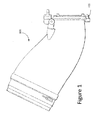
Figure 1 shows an exemplary transition piece.Transition piece 100 may be coupled at an upstream end to a combustor and at a downstream or aft end to a turbine. Thetransition piece 100 carries hot gas flow from the combustor to the turbine. Theaft frame 105 is a component which is located at the exit or aft end of the transition piece and thus acts as an interface between thetransition piece 100 and the stage 1 nozzle. Theaft frame 105 is exposed to hot gases flowing into the stage 1 nozzle. -
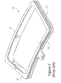
Figure 2 is an exemplary, prior art embodiment of an aft frame.Aft frame 200 has anaft face 212 and insidewall 210. Insidewall 210 intersects withface 212 at a sharp, approximate 90 degree, angle.Aft frame 200 has atop rail 205 andbottom rail 215 as well as aleft side rail 207 andright side rail 220. - A potential cause of thermal distress of prior art aft frame side rails may be due to ingestion of hot gas exiting the transition piece, trapping the hot gas and recirculating it between the stage one nozzle vane and aft face of the aft frame.
- For example, with reference to
Figure 2 , as typical in the prior art, the aforementioned ingestion may be deflected back towards theaft face 212 of the transitionpiece aft frame 200 because of the circumferential proximity of the stage one nozzle vane to theaft frame 200 and the blunt body effects of theaft face 212, which is normal to the aft frameinner wall 210 in the direction of transition piece exit flow. As disclosed herein, the shape of the aft frame side rails (or the entire perimeter of the aft frame) may be altered to minimize hot gas recirculation. - In an embodiment, the prior art shape of the transition piece aft frame face and the normal aft frame inner wall may be changed to create an airfoil shape on each of the aft frame side rails.
Figure 3 is an exemplary cut corner perspective view of an aft frame with a contoured or rounded airfoil face.Figure 4 is an exemplary front view of anaft frame 400 with a contoured aft face.Figure 5 is a cross section taken along line 401-401 ofFigure 4 . - A gas turbine configuration may allow for adjacent transition pieces and corresponding aft frames. With reference to
Figure 6 ,transition piece 600 andcorresponding aft frame 605 may be adjacent totransition piece 607 andcorresponding aft frame 610.Figure 7 is an exemplary cross section taken along line 601 - 601 ofFigure 6 . InFigure 7 , 705 corresponds toaft frame aft frame 610.Figure 8 is an exemplary cross section of adjacent aft frames from the prior art with inner walls normal to the aft frame front exit. - Transition piece aft frames configured as shown in
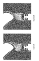
Figure 8 may create a large bluff body with their side spans when assembled side by side within the gas turbine. As stated herein, this aft frame configuration may create a recirculation zone that when positioned upstream of a stage one nozzle can circulate hot gases back towards the transition piece aft frame and cause damage. Aft frames with an airfoil shape (e.g., a contour), as shown inFigure 7 , may reduce the recirculation zone.Figures 9 and 10 are representations of computational flow dynamics contours.Figure 9 is an exemplary illustration of the wake of a flat aft frame face (e.g.,Figure 2 and8 ).Figure 10 is an exemplary illustration of a wake of contour shape aft frame face (e.g.,Figure 3 and7 ). The wake of the adjacent aft frames with a contoured aft frame face inFigure 10 is more stable than the wake of the flat face aft frame inFigure 9 .Figure 11 is an exemplary illustration of cross section of adjacent contoured aft frames and arrows showing an exemplary flow of cooling vectors. The cooling air pushes hot gases away from the cavities between hardware. -
Figure 12 is an exemplary embodiment of an asymmetrical air foil shape of a cross section of adjacent aft frames. To further optimize the flow field and minimize ingestion, the inner diameter of two adjacent side rails of adjacent aft frames may be tapered in the same direction (creating an asymmetric aft frame). The adjacent aft frame taper may be based on the taper of the stage one nozzle vane. -
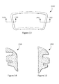
Figure 13 is an exemplary illustration of a front view of an aft frame.Figure 14 is an exemplary cross section taken along line 1301 - 1301 ofaft frame 1300.Figure 15 is an exemplary cross section taken along line 1302 - 1302 ofaft frame 1300. The singleaft frame 1300 may have asymmetric contours on the side rails as shown bycross section 1400 andcross section 1500. The asymmetric contours of a single aft frame exit may be contoured in a manner that is oriented towards the stage one nozzle. - Currently, typical aft frame configurations incorporate cooling holes with circular cross sections in order to divert a portion of flow through an impingement sleeve (which surrounds the transition piece) into these holes to cool the aft frame. Embodiments of the aft frame face as discussed herein that use an airfoil shape of the aft frame exit provide an alternative method of reducing aft frame metal temperatures. Cooling holes on side rails may no longer be needed. Additional backside cooling of the aft frame airfoil may be added to protect the outer thermal barrier coating. Eliminating the flat aft frame face and creating an airfoil shape, may simplify fabrication processes. Cooling holes may be removed on the side rail which may eliminate a percentage of the electrical discharge machining (EDM) holes. In addition, thermal barrier coating (TBC) may be applied down the transition piece body and over the airfoil face to a side seal, which may now cover the entire transition piece surface exposed to hot gas.
Figure 16 is an exemplary illustration of a cross section of an airfoil shaped aft frame. The combination of contour shape and cooling hole angle, as shown inFigure 16 , may produce a film cooling on the transition piece aft end. -
Figure 17 is an exemplary illustration of adjacent aft frames with an airfoil shape transition piece aft frame face that has a more angular shape.Figure 18 is an exemplary illustration of adjacent aft frames with aft frame side spans designed to spoil the effects of hot gas recirculation and ingestion.Spoiler 1801 of the aft frame exit may separate the flow and reduce the recirculation zone. In addition, cooling or purge holes can be added to the back side of the spoilers to further breakdown the recirculation zone. - Turbines and compressors designs may vary so design-of-experiments (DOE) methods for combining sets of computational fluid dynamics (CFD) and other analysis techniques may be used to optimize the various geometries (e.g., radius of contour of the aft frame) that maximize the results for the particular system. Although side rails of the aft frame are discussed, the entire perimeter of the aft frame face may have an airfoil shape. In addition, although an aft frame is discussed, the embodiments disclosed herein may apply to any apparatus separate from or integrated with the transition piece in a similar position as the aft frame at the transition piece aft end exit.
- In describing preferred embodiments of the subject matter of the present disclosure, as illustrated in the Figures, specific terminology is employed for the sake of clarity. The claimed subject matter, however, is not intended to be limited to the specific terminology so selected, and it is to be understood that each specific element includes all technical equivalents that operate in a similar manner to accomplish a similar purpose.
- This written description uses examples to disclose the invention, including the best mode, and also to enable any person skilled in the art to practice the invention, including making and using any devices or systems and performing any incorporated methods. The patentable scope of the invention is defined by the claims, and may include other examples that occur to those skilled in the art. Such other examples are intended to be within the scope of the claims if they have structural elements that do not differ from the literal language of the claims, or if they include equivalent structural elements with insubstantial differences from the literal languages of the claims.
- Various aspects and embodiments of the present invention are defined by the following numbered clauses:
- 1. An apparatus comprising:
- an aft frame, wherein an aft frame exit face of the aft frame has an airfoil shape.
- 2. The apparatus of clause 1, wherein the airfoil shape is a contoured shape.
- 3. The apparatus of any preceding clause, wherein the airfoil shape is based on an interaction of hot gas flow with a stage one nozzle vane.
- 4. The apparatus of any preceding clause, the aft frame exit face side rails comprises an airfoil shape.
- 5. The apparatus of any preceding clause, wherein the aft frame comprises a first side rail and a second side rail, wherein the first and second side rails are asymmetric.
- 6. The apparatus of any preceding clause, wherein the aft frame exit face has backside cooling holes.
- 7. The apparatus of any preceding clause, wherein the aft frame has features designed to spoil the effects of hot gas recirculation and ingestion.
- 8. The apparatus of any preceding clause, wherein the aft frame exit face has a contour shape and cooling hole angle that produces film cooling on the aft frame exit.
- 9. A transition piece comprising an aft exit that has an airfoil shape.
- 10. The transition piece of any preceding clause, wherein the airfoil shape is a contoured shape.
- 11. The transition piece of any preceding clause, wherein the airfoil shape is based on an interaction of hot gas flow with a stage one nozzle vane.
- 12. The transition piece of any preceding clause, wherein the aft exit comprises a first side rail and a second side rail, wherein the first and second side rails are asymmetric.
- 13. The transition piece of any preceding clause, wherein the aft exit has features designed to spoil the effects of hot gas recirculation and ingestion.
- 14. The transition piece of any preceding clause, wherein the aft exit has a contour shape and cooling hole angle that produces film cooling on the aft exit.
- 15. A system comprising:
- a first aft frame comprising an airfoil shape of a face of the first aft frame; and
- a second aft frame in proximity to the first aft frame comprising an airfoil shape of a face of the second aft frame.
- 16. The system of any preceding clause, the airfoil shape of the first aft frame is based on an interaction of hot gas flow with a stage one nozzle vane.
- 17. The system of any preceding clause, wherein the airfoil shape of the first aft frame is a contoured shape.
- 18. The system of any preceding clause, wherein the face of the first aft frame has an airfoil shape that is asymmetrical to the face of the second aft frame.
- 19. The system of any preceding clause, wherein the aft frame has features designed to spoil the effects of hot gas recirculation and ingestion.
- 20. The system of any preceding clause, wherein the aft frame exit face has a contour shape and cooling hole angle that produces film cooling on the aft frame exit.
Claims (15)
- An apparatus comprising:an aft frame (400), wherein an aft frame exit face of the aft frame (400) has an airfoil shape.
- The apparatus of claim 1, wherein the airfoil shape is a contoured shape.
- The apparatus of claim 1 or claim 2, wherein the airfoil shape is based on an interaction of hot gas flow with a stage one nozzle vane.
- The apparatus of claim 1, 2 or 3, the aft frame exit face side rails comprises an airfoil shape.
- The apparatus of any one of claims 1 to 4, wherein the aft frame comprises a first side rail and a second side rail, wherein the first and second side rails are asymmetric.
- The apparatus of any preceding claim, wherein the aft frame exit face has backside cooling holes.
- The apparatus of any preceding claim, wherein the aft frame has features designed to spoil the effects of hot gas recirculation and ingestion.
- The apparatus of claim 1, wherein the aft frame exit face has a contour shape and cooling hole angle that produces film cooling on the aft frame exit.
- A transition piece (600) comprising an aft exit that has an airfoil shape.
- The transition piece of claim 9, wherein the airfoil shape is a contoured shape.
- The transition piece of claim 9 or claim 10, wherein the airfoil shape is based on an interaction of hot gas flow with a stage one nozzle vane.
- The transition piece of claim 9, 10 or 11, wherein the aft exit comprises a first side rail and a second side rail, wherein the first and second side rails are asymmetric.
- The transition piece of any one of claims 9 to 12, wherein the aft exit has features designed to spoil the effects of hot gas recirculation and ingestion.
- The transition piece of any one of claims 9 to 13, wherein the aft exit has a contour shape and cooling hole angle that produces film cooling on the aft exit.
- A system comprising:a first aft frame comprising an airfoil shape of a face of the first aft frame; anda second aft frame in proximity to the first aft frame comprising an airfoil shape of a face of the second aft frame.
Applications Claiming Priority (1)
| Application Number | Priority Date | Filing Date | Title |
|---|---|---|---|
| US13/416,559 US20130236301A1 (en) | 2012-03-09 | 2012-03-09 | Apparatus And System For Directing Hot Gas |
Publications (2)
| Publication Number | Publication Date |
|---|---|
| EP2636847A2 true EP2636847A2 (en) | 2013-09-11 |
| EP2636847A3 EP2636847A3 (en) | 2015-10-14 |
Family
ID=47844132
Family Applications (1)
| Application Number | Title | Priority Date | Filing Date |
|---|---|---|---|
| EP13157969.0A Withdrawn EP2636847A3 (en) | 2012-03-09 | 2013-03-06 | Apparatus and system for directing hot gas |
Country Status (5)
| Country | Link |
|---|---|
| US (1) | US20130236301A1 (en) |
| EP (1) | EP2636847A3 (en) |
| JP (1) | JP2013185814A (en) |
| CN (1) | CN103306746A (en) |
| RU (1) | RU2013110040A (en) |
Families Citing this family (4)
| Publication number | Priority date | Publication date | Assignee | Title |
|---|---|---|---|---|
| EP3124749B1 (en) * | 2015-07-28 | 2018-12-19 | Ansaldo Energia Switzerland AG | First stage turbine vane arrangement |
| US10443415B2 (en) | 2016-03-30 | 2019-10-15 | General Electric Company | Flowpath assembly for a gas turbine engine |
| US10865660B2 (en) | 2017-09-12 | 2020-12-15 | DOOSAN Heavy Industries Construction Co., LTD | Transition piece support structure, gas turbine combustor including same, and method of installing same |
| US12152502B2 (en) | 2021-10-29 | 2024-11-26 | Pratt & Whitney Canada Corp. | Selectively coated gas path surfaces within a hot section of a gas turbine engine |
Family Cites Families (13)
| Publication number | Priority date | Publication date | Assignee | Title |
|---|---|---|---|---|
| US3657884A (en) * | 1970-11-20 | 1972-04-25 | Westinghouse Electric Corp | Trans-nozzle steam injection gas turbine |
| US4465284A (en) * | 1983-09-19 | 1984-08-14 | General Electric Company | Scalloped cooling of gas turbine transition piece frame |
| US5414999A (en) * | 1993-11-05 | 1995-05-16 | General Electric Company | Integral aft frame mount for a gas turbine combustor transition piece |
| US5749218A (en) * | 1993-12-17 | 1998-05-12 | General Electric Co. | Wear reduction kit for gas turbine combustors |
| EP0718468B1 (en) * | 1994-12-20 | 2001-10-31 | General Electric Company | Transition piece frame support |
| US6412268B1 (en) * | 2000-04-06 | 2002-07-02 | General Electric Company | Cooling air recycling for gas turbine transition duct end frame and related method |
| JP2004202544A (en) * | 2002-12-25 | 2004-07-22 | Daido Steel Co Ltd | Method of manufacturing polygonal annular body part having irregular cross section |
| US6860108B2 (en) * | 2003-01-22 | 2005-03-01 | Mitsubishi Heavy Industries, Ltd. | Gas turbine tail tube seal and gas turbine using the same |
| US8245515B2 (en) * | 2008-08-06 | 2012-08-21 | General Electric Company | Transition duct aft end frame cooling and related method |
| JP5479058B2 (en) * | 2009-12-07 | 2014-04-23 | 三菱重工業株式会社 | Communication structure between combustor and turbine section, and gas turbine |
| US20110162378A1 (en) * | 2010-01-06 | 2011-07-07 | General Electric Company | Tunable transition piece aft frame |
| US20110259015A1 (en) * | 2010-04-27 | 2011-10-27 | David Richard Johns | Tangential Combustor |
| JP5848074B2 (en) * | 2011-09-16 | 2016-01-27 | 三菱日立パワーシステムズ株式会社 | Gas turbine, tail cylinder and combustor |
-
2012
- 2012-03-09 US US13/416,559 patent/US20130236301A1/en not_active Abandoned
-
2013
- 2013-03-04 JP JP2013041370A patent/JP2013185814A/en active Pending
- 2013-03-06 EP EP13157969.0A patent/EP2636847A3/en not_active Withdrawn
- 2013-03-06 RU RU2013110040/06A patent/RU2013110040A/en not_active Application Discontinuation
- 2013-03-08 CN CN201310074011XA patent/CN103306746A/en active Pending
Non-Patent Citations (1)
| Title |
|---|
| None |
Also Published As
| Publication number | Publication date |
|---|---|
| RU2013110040A (en) | 2014-09-20 |
| JP2013185814A (en) | 2013-09-19 |
| CN103306746A (en) | 2013-09-18 |
| US20130236301A1 (en) | 2013-09-12 |
| EP2636847A3 (en) | 2015-10-14 |
Similar Documents
| Publication | Publication Date | Title |
|---|---|---|
| US9988923B2 (en) | Seal for gas turbine engine | |
| US10753216B2 (en) | Sliding baffle inserts | |
| US10612392B2 (en) | Gas turbine engine component with conformal fillet cooling path | |
| EP3088675A1 (en) | Rotor blade having a flared tip and corresponding gas turbine | |
| US10227875B2 (en) | Gas turbine engine component with combined mate face and platform cooling | |
| EP3088674A1 (en) | Rotor blade and corresponding gas turbine | |
| US10309228B2 (en) | Impingement insert for a gas turbine engine | |
| US20130209250A1 (en) | Transition piece seal assembly for a turbomachine | |
| US9863259B2 (en) | Chordal seal | |
| US10196900B2 (en) | Heat transfer pedestals with flow guide features | |
| US20160146016A1 (en) | Rotor rim impingement cooling | |
| BR102016004205A2 (en) | engine component for a gas turbine engine | |
| EP2636847A2 (en) | Apparatus and system for directing hot gas | |
| JP5679246B1 (en) | High-temperature component of gas turbine, gas turbine including the same, and method for manufacturing high-temperature component of gas turbine | |
| US10280793B2 (en) | Insert and standoff design for a gas turbine engine vane | |
| EP2948634B1 (en) | Gas turbine engine component with angled aperture impingement | |
| US10392945B2 (en) | Turbomachine cooling system | |
| US10138743B2 (en) | Impingement cooling system for a gas turbine engine | |
| US10544694B2 (en) | Cooling pocket for turbomachine nozzle | |
| US20180038236A1 (en) | Gas turbine engine stator vane baffle arrangement | |
| US10815803B2 (en) | BOAS thermal protection | |
| EP2620592A1 (en) | Airfoil for a gas turbine engine having a tubular impingement element | |
| US20160160652A1 (en) | Cooled pocket in a turbine vane platform | |
| KR20150072224A (en) | Airfoil for a turbin |
Legal Events
| Date | Code | Title | Description |
|---|---|---|---|
| PUAI | Public reference made under article 153(3) epc to a published international application that has entered the european phase |
Free format text: ORIGINAL CODE: 0009012 |
|
| AK | Designated contracting states |
Kind code of ref document: A2 Designated state(s): AL AT BE BG CH CY CZ DE DK EE ES FI FR GB GR HR HU IE IS IT LI LT LU LV MC MK MT NL NO PL PT RO RS SE SI SK SM TR |
|
| AX | Request for extension of the european patent |
Extension state: BA ME |
|
| PUAL | Search report despatched |
Free format text: ORIGINAL CODE: 0009013 |
|
| AK | Designated contracting states |
Kind code of ref document: A3 Designated state(s): AL AT BE BG CH CY CZ DE DK EE ES FI FR GB GR HR HU IE IS IT LI LT LU LV MC MK MT NL NO PL PT RO RS SE SI SK SM TR |
|
| AX | Request for extension of the european patent |
Extension state: BA ME |
|
| RIC1 | Information provided on ipc code assigned before grant |
Ipc: F01D 9/02 20060101AFI20150908BHEP Ipc: F23R 3/46 20060101ALI20150908BHEP |
|
| 17P | Request for examination filed |
Effective date: 20160414 |
|
| RBV | Designated contracting states (corrected) |
Designated state(s): AL AT BE BG CH CY CZ DE DK EE ES FI FR GB GR HR HU IE IS IT LI LT LU LV MC MK MT NL NO PL PT RO RS SE SI SK SM TR |
|
| STAA | Information on the status of an ep patent application or granted ep patent |
Free format text: STATUS: THE APPLICATION IS DEEMED TO BE WITHDRAWN |
|
| 18D | Application deemed to be withdrawn |
Effective date: 20171003 |