EP2636822A2 - Lock mechanism - Google Patents
Lock mechanism Download PDFInfo
- Publication number
- EP2636822A2 EP2636822A2 EP12183956.7A EP12183956A EP2636822A2 EP 2636822 A2 EP2636822 A2 EP 2636822A2 EP 12183956 A EP12183956 A EP 12183956A EP 2636822 A2 EP2636822 A2 EP 2636822A2
- Authority
- EP
- European Patent Office
- Prior art keywords
- lock
- control
- head
- control element
- lock mechanism
- Prior art date
- Legal status (The legal status is an assumption and is not a legal conclusion. Google has not performed a legal analysis and makes no representation as to the accuracy of the status listed.)
- Granted
Links
Images

Classifications
-
- E—FIXED CONSTRUCTIONS
- E05—LOCKS; KEYS; WINDOW OR DOOR FITTINGS; SAFES
- E05B—LOCKS; ACCESSORIES THEREFOR; HANDCUFFS
- E05B47/00—Operating or controlling locks or other fastening devices by electric or magnetic means
- E05B47/0001—Operating or controlling locks or other fastening devices by electric or magnetic means with electric actuators; Constructional features thereof
- E05B47/0012—Operating or controlling locks or other fastening devices by electric or magnetic means with electric actuators; Constructional features thereof with rotary electromotors
-
- E—FIXED CONSTRUCTIONS
- E05—LOCKS; KEYS; WINDOW OR DOOR FITTINGS; SAFES
- E05B—LOCKS; ACCESSORIES THEREFOR; HANDCUFFS
- E05B47/00—Operating or controlling locks or other fastening devices by electric or magnetic means
- E05B47/06—Controlling mechanically-operated bolts by electro-magnetically-operated detents
- E05B47/0607—Controlling mechanically-operated bolts by electro-magnetically-operated detents the detent moving pivotally or rotatively
-
- E—FIXED CONSTRUCTIONS
- E05—LOCKS; KEYS; WINDOW OR DOOR FITTINGS; SAFES
- E05B—LOCKS; ACCESSORIES THEREFOR; HANDCUFFS
- E05B47/00—Operating or controlling locks or other fastening devices by electric or magnetic means
- E05B2047/0094—Mechanical aspects of remotely controlled locks
-
- E—FIXED CONSTRUCTIONS
- E05—LOCKS; KEYS; WINDOW OR DOOR FITTINGS; SAFES
- E05B—LOCKS; ACCESSORIES THEREFOR; HANDCUFFS
- E05B45/00—Alarm locks
- E05B45/06—Electric alarm locks
-
- G—PHYSICS
- G08—SIGNALLING
- G08B—SIGNALLING SYSTEMS, e.g. PERSONAL CALLING SYSTEMS; ORDER TELEGRAPHS; ALARM SYSTEMS
- G08B25/00—Alarm systems in which the location of the alarm condition is signalled to a central station, e.g. fire or police telegraphic systems
- G08B25/008—Alarm setting and unsetting, i.e. arming or disarming of the security system
Definitions
- This invention relates to a lock mechanism. It also relates to a lock incorporating the lock mechanism.
- a typical lock comprises a lock bolt that is received within a keep when the lock is activated. When the lock is deactivated the lock bolt can be withdrawn from the keep.
- a lock mechanism is typically used to selectively restrict or control movement of a lock and/or control the lock bolt.
- Certain locks and lock mechanisms such as those for key boxes or safes and the like, are required to be particularly robust. These types of locks must be able to withstand large forces, particularly when attacked, yet still operate smoothly and reliably.
- a lock mechanism comprising a control element arranged for rotation about an axis between an active position and an inactive position, the control element including a control head having at least one axially extending projection, the lock mechanism further comprising a lock element that is axially aligned with the control element and includes a lock element head, the lock element head having at least one axially extending projection, the projection(s) of the control head and the projection(s) of the lock element head arranged such that in the active position, the lock element and control element are held apart by the projections and in the inactive position, the projections can mesh together to permit axial movement of the lock element relative to the control element.
- the lock mechanism can be constructed such that it is very robust for its size.
- the intermeshing projections provide an easy to manufacture and reliable way to control the motion of the lock element.
- the lock element comprises an elongate body having the at least one projection at one end and a lock bolt at an opposed end, the lock bolt adapted to be received within a keep of a lock.
- the lock element or lock bolt may be adapted to actuate a further mechanism of greater strength, for example.
- At least one of the projections includes a narrower tip that is narrower than the remainder of the projection or tapers. This will allow the projections to mesh together more easily as the tip, which could be conical or frustoconical, guides the projections to intermesh.
- control head has at least two axially extending projections and the lock element head may have a complementary number of axially extending projections.
- control head is castellated and thus the castellations form the at least one projection.
- lock element head is castellated, the castellations on the lock element head being complimentary to the castellations on the control head.
- the castellations are arranged in a ring.
- one of the control head and lock element head may comprise a single projection having bores therein, the bores arranged to receive complimentary pins on the other of the control head and lock element head when in the inactive position such that the pins are received within the bores and thus mesh together, and in the active position, the pins are not aligned with the bores and the control element and lock element are held apart.
- the projection on the control head or the projection on the lock element head is shaped such that the rotational motion of the control element is converted to axial motion of the lock element.
- the projection may have a lead-in portion inclined to the axial direction arranged to bear against the other projection such that rotation of the control element moves the lock element in the axial direction. This is advantageous as rotation of the control element can be arranged to drive the control element and lock element apart so that the lock element can engage a lock keep, for example.
- control element and the lock element are received within a housing and are axially slidable therein, the lock mechanism including a biasing element to urge the control element and lock element apart.
- the housing forms a guide such that the control element and lock mechanism can move axially relative to one another. This arrangement is advantageous as the lock element and control element can "float" in the housing, which has been found to result in a more reliable mechanism as tolerances do not need to be strictly controlled.
- the housing comprises an abutment end plate at one end arranged to contact the control element.
- the abutment end plate is adapted to form a mount for a motor for rotating the control element between the active and inactive positions.
- the end plate is advantageous as it transfers forces applied to the control element to the housing rather than the forces being transferred to the motor.
- control element comprises a tubular body having the control head at one end.
- the tubular body of the control element is arranged to receive a motor for rotating the control element between the active and inactive positions, wherein the motor is mounted to an abutment end plate of the housing.
- the motor is mounted to an abutment end plate of the housing.
- the motor comprises a spindle to engage an aperture in the control element, the aperture and spindle being arranged such that the spindle is axially slidable within the aperture.
- the spindle is shaped such that it can rotate the control element, but it can also slide axially. This helps to isolate the motor from any forces experienced by the control element, when the lock mechanism is attacked, for example.
- the abutment plate may include an aperture for receiving a rod that, at a first end, engages the control element and at a second end is coupled to a motor for rotating the control element that is mounted outside of a housing of the lock mechanism.
- the housing comprises an aperture in one end to allow the lock element to project from the housing.
- the lock mechanism includes a withdrawal means for withdrawing the lock element when the control element is in the inactive position.
- the withdrawal means may comprise a slider projecting from the lock element, the slider adapted to be moved by a user to withdraw the lock element.
- the slider may be actuated by a handle.
- the withdrawal means may comprise a withdrawal motor arranged to withdraw the lock element. This is advantageous as the withdrawal motor can be controlled in combination with the motor that operates the control element so that the two motors can operate together or sequentially.
- the lock mechanism may include two lock elements adapted to project from opposed ends and the control element may include at least one projection at both ends and a middle support plate may provide support to a midsection of the control element. This is advantageous as the middle support plate can be connected to a housing and engage a groove in the midsection of the control element.
- the middle support plate may provide a mount for a motor.
- a lock having the lock mechanism of the first aspect of the invention, the lock element comprising a lock bolt at one end, opposed the lock element head, for engaging a keep.
- the lock mechanism can easily be integrated into a lock.
- the lock may be integrated in a door, a strong box, an electronic padlock, a deadbolt, a deadbolt lock or a key box, for example.
- the lock includes withdrawal means for withdrawing the lock bolt from the keep.
- the lock element and control element are arranged such that the throw of the lock bolt is determined by the depth of the projections.
- the amount the projections can mesh together controls the throw of the lock bolt.
- the lock bolt is fixedly secured to or integral with the lock element.
- the lock bolt comprises a rod having a substantially flat edge for engaging the keep; a cylindrical member; or a ball bearing.
- a lock mechanism 1 is shown in the Figures 1 to 3 , which is arranged to be integrated into a key box. It will be appreciated that the lock mechanism 1 is perfectly suited for integration into other arrangements where a robust and reliable lock mechanism is required.
- the lock mechanism 1 comprises a control element 2 arranged for rotation about an axis A between an active position (shown in Figure 2 ) and an inactive position (shown in Figure 3 ).
- the control element 2 includes a control head 3 at one end having four circumferentially spaced projections 4a-d extending axially therefrom. Thus, the four projections have four gaps therebetween.
- the lock mechanism 1 further comprises a lock element 5 that is axially aligned with the control element 2 and includes a lock element head 6.
- the lock element head 6 faces the control head 3.
- the lock element head 6 has, at its end, four circumferentially spaced projections 7a-d extending axially therefrom. Thus, the four projections have four gaps therebetween.
- the projections 4a-d of the control head 3 and the projections 7a-d of the lock element head 6 are arranged such that in the active position, the lock element 5 and control element 2 are held apart by the projections 4, 7 and in the inactive position, the projections 4 and 7 can mesh together to permit axial movement of the lock element 6 relative to the control element 2.
- the control element 2 comprises a substantially tubular body 8 of circular cross-section that is closed at one end by the control head 3. At the opposite end, the control element 2 comprises an abutment rim 10.
- the abutment rim 10 includes a part-circumferential cut-out 11, which is used to limit the rotational movement of the control element 2, as will be described in more detail below.
- the projections 4 of the control head 3 form a ring of castellations.
- the ring of castellations define a central region 12 of the control head 3 adapted to receive a biasing element 13 comprising a coil spring.
- the control head 3 also includes an aperture 14 that connects the inside of the tubular body 8 to the central region 12.
- the aperture 14 is keyed and in this embodiment is semicircular in cross-section.
- the lock element 5 comprises a substantially cylindrical body 16.
- the lock element head 6 extends from a first end of the body 16.
- the opposed second end of the body comprises a bolt 17.
- the bolt 17 is arranged to fit within a keep (not shown) of the key box lock that the lock mechanism is mounted.
- the lock element 5 includes withdrawal means (not visible) that allows the bolt 17 of the lock element 5 to be withdrawn.
- the withdrawal means comprises a withdrawal rod that extends radially so that the bolt 17 can be withdrawn by a user.
- the lock element 5 also includes an axially facing ledge 19 that surrounds the bolt 17.
- the control element 2 and lock element 5 are slidingly mounted within a housing 18.
- the housing 18 provides a guiding channel in which the control element 2 and lock element 5 can slide axially.
- the control element 2 and lock element 5 are biased apart by the biasing element 13 and therefore "float" within the housing 18.
- the housing 18 has a bolt aperture 17' that allows the bolt 17 to project from the housing 18 so that it can engage the keep of the lock when in use.
- the bolt aperture 17' and bolt 17 are keyed to restrict rotation of the bolt 17 and therefore the lock element 5.
- the housing also includes a longitudinal slot (not visible) that allows the radially extending withdrawal rod to extend through the housing and move the lock element 5 when required.
- the end plate 20 includes a mounting area 21 for a motor 22.
- the housing 18 is formed integrally with the abutment end plate 20, although they are shown as separate items in the Figures for clarity. The contents of the housing 18 is thus loaded therein through the end opposed to the abutment end plate 20 and then an end cap including the aperture 17' is affixed to the housing by welding, for example.
- the motor 22 includes a spindle 23 that is received within the keyed aperture 14.
- the spindle 23 is also keyed so that the motor 22 can rotate the control element 2.
- the spindle 23, although keyed for rotation, is axially slidable in the aperture 14.
- the mounting area 21 is surrounded by a support track 25, which is arranged to abut the abutment rim 10.
- the support track 25 is annular and includes a stop peg 24.
- the stop peg 24 is arranged to project into the cut-out 11 and thus limits the amount that the control element 2 can rotate, as the stop peg 24 will contact the sides of the cut-out 11. This arrangement is particularly advantageous as any force that is subjected to the housing 18 is transferred via the end plate 20 to the housing 18.
- the motor 22 is isolated from the force as the control element 2 is arranged to abut the end-plate and not bear on the motor 2 and the spindle 23 is axially slidable in the aperture 14.
- Figures 2 and 3 show the lock mechanism 1 with the housing 18 removed to reveal the position of the control element 2 and lock element 5 in use.
- Figure 2 shows the active position in which the control element 2 and lock element 5 are biased apart by the biasing element 13. Accordingly, the control element 2 abuts the support track 25 and the ledge 19 of the lock element 5 abuts the housing 18 adjacent the bolt aperture 17'.
- the control element 2 is at a rotational position where the projections 4a-d of the control head 2 are aligned with the projections 7a-d of the lock element head 6.
- the bolt 17 is maintained in its extended position where it extends into the keep of the key box lock (not shown).
- the stop peg 24 abuts a first side of the cut-out 11 in the active position. Any force that is applied to the bolt 17, such as if the lock is attacked, will be transferred to the housing 18 or through the control element 8 and the end plate 20 to the housing 18.
- the force on the motor 22 and spring 13 is kept to a low level so that they are not damaged. Therefore, it is relatively easy and cost effective to manufacture the housing 18, end plate 20, lock element 5 and control element 2 of robust materials.
- the arrangement of the lock mechanism 1 is particularly advantageous as it reduces the forces on the more delicate components, which ensures reliable operation.
- the housing can be made of a strength or thickness to suit the intended use for the lock mechanism.
- the control element 2 Upon actuation of the motor 22, the control element 2 is rotated through approximately 45° such that is adopts the inactive position. Accordingly the stop peg 24 now abuts an opposed side of the cut-out 11.
- the projections 4a-d of the control head 2 are aligned with the gaps between the projections 7a-d of the lock element head 6.
- the projections 7a-d of the lock element head 6 are aligned with the gaps between the projections 4a-d of the control head 2 so that the projections can move into the respective gaps.
- the withdrawal means rod can then be used to withdraw the lock element 5 axially towards the control element 2 such that the projections 4a-d mesh between the projections 7a-d and vice-versa. Withdrawal of the control element 2 withdraws the bolt 17 out of the keep of the key box, allowing the key box to be opened.
- the bolt 17 is returned to the keep, perhaps with manipulation of the withdrawal means.
- the biasing element 13 urges the control element 2 and lock element 5 apart and thus the bolt 17 adopts its extended position through the bolt aperture 17'.
- the projections 4a-d and 7a-d are thus no longer meshed together.
- the motor 22 can then be actuated to rotate the control element 2 to the active position in which the projections are aligned end to end.
- control element 2 and the lock element 5 have been shown having four projections each, they may have more or less projections or different numbers of projections.
- the housing and thus the control element 2 and lock element 5 are described as substantially cylindrical, although they could be alternative shapes provided that relative movement in the axial direction is possible and the control element is able to rotate about its axis.
- the embodiment of the lock mechanism 1 described above is for integration into a key box. It will be appreciated that the mechanism 1 can be used in any appropriate lock where a high strength, attack resistant, simple and reliable mechanism is required.
- the lock bolt 17 may comprise a ball bearing that projects though an aperture 17'. In the inactive position, the ball bearing operates as a strike mechanism and can ride into and out of the keep against the force of spring 13. When the lock mechanism is in the active position, the ball bearing is held, projecting from the lock mechanism, in the keep.
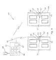
- FIG. 4 shows a locking system 40 that uses the lock mechanism 1 described above.
- the locking system 40 is a security device for remote locking of the internal or external doors of a property, possibly in response to the detection of an unauthorised intrusion into the building.
- the locking system 40 in this embodiment comprises a lock control panel 41, a first lock mechanism 42 loaded into a first internal door 43 of a building and a second lock mechanism 44 loaded into a second internal door 45 of a building.
- the lock control panel 41 includes a key panel 46 for receiving the input of a code, a controller 47 and an antenna 48.
- the controller 47 is arranged to receive a code from the key panel 46 in order to "arm” and “disarm” the controller 47.
- the controller 47 also receives input from an intrusion detection device 50, which may comprise a Passive Infra Red (PIR) sensor.
- PIR Passive Infra Red
- the controller acts on the input by sending command signals, via the antenna 48, to the first and second lock mechanisms 42, 44. Accordingly, the controller includes wireless communication means to communicate with the lock mechanisms 42, 44.
- the lock mechanisms 42, 44 are similar and therefore only one lock mechanism will be described and the same reference numerals are used to describe corresponding parts but with an additional dash when applied to the second lock mechanism 44 and second door 45.
- the lock mechanism 42, 44 has a withdrawal means in the form of a handle 51, 51'.
- the handle 51, 51' is able to withdraw the lock bolt 52, 52' from its keep 53, 53' when the lock mechanism is inactive.
- the keep is mounted in a door frame 54, 54'.
- the lock mechanism 42, 44 includes a lock mechanism controller 55, 55'.
- the lock mechanism controller is arranged to receive command signals from the controller 47 via an antenna 56, 56'.
- the lock mechanism controller 55, 55' includes wireless communication means. It will be appreciated that the controllers 55, 55' and antennas 56, 56' are contained with a lock unit that can be retrofitted to existing doors in place of the existing lock. This is advantageous as the lock unit can be installed simply, with no modification to the door or the aperture in the door for the lock. The small size and high strength of the lock mechanism allows the lock unit to be a suitable size for retrofit applications.
- the lock mechanisms 42, 44 are normally inactive and therefore the doors 43, 45 can be opened by their handles 51, 51'.
- the controller 47 waits for input from the intrusion detection device 50. If an intrusion is detected, the controller 47 sends a control signal to the lock mechanisms 42, 44, which is received by their associated lock mechanism controllers 55, 55'.
- the lock mechanism controllers 55, 55' cause the motors 22 in the lock mechanisms to actuate to move the control element 2 to the active position, whereby the doors 43, 45 are locked and the withdrawal of the lock bolts 52, 52' from their respective keeps 53, 53' is prevented.
- the locking system 40 can be disarmed and the doors 43, 45 opened by input of the predetermined code into the key panel 46.
- the controller 47 then sends control signals to cause the lock mechanism controllers 55, 55' to deactivate their respective lock mechanisms.
- locking system there may be more or less doors secured; more or less intrusion detection devices; different types of intrusion detection device; the use of encrypted control signals; the incorporation of anti-tampering features; the incorporation into an burglar alarm system; the use of safety systems and panic buttons to prevent legitimate occupants of the building from becoming trapped and other changes or enhancements that will be clear to those skilled in the art.
- the main advantage of the locking system is that the locking mechanism of the invention, due to its small size and high strength, can be incorporated into doors and windows to form locking systems that were previously impractical and/or expensive.
Landscapes
- Lock And Its Accessories (AREA)
- Power-Operated Mechanisms For Wings (AREA)
- Snaps, Bayonet Connections, Set Pins, And Snap Rings (AREA)
- Mechanical Control Devices (AREA)
Abstract
Description
- This invention relates to a lock mechanism. It also relates to a lock incorporating the lock mechanism.
- A typical lock comprises a lock bolt that is received within a keep when the lock is activated. When the lock is deactivated the lock bolt can be withdrawn from the keep. A lock mechanism is typically used to selectively restrict or control movement of a lock and/or control the lock bolt.
- Certain locks and lock mechanisms, such as those for key boxes or safes and the like, are required to be particularly robust. These types of locks must be able to withstand large forces, particularly when attacked, yet still operate smoothly and reliably.
- According to a first aspect of the invention we provide a lock mechanism comprising a control element arranged for rotation about an axis between an active position and an inactive position, the control element including a control head having at least one axially extending projection, the lock mechanism further comprising a lock element that is axially aligned with the control element and includes a lock element head, the lock element head having at least one axially extending projection, the projection(s) of the control head and the projection(s) of the lock element head arranged such that in the active position, the lock element and control element are held apart by the projections and in the inactive position, the projections can mesh together to permit axial movement of the lock element relative to the control element.
- This is advantageous as the lock mechanism can be constructed such that it is very robust for its size. The intermeshing projections provide an easy to manufacture and reliable way to control the motion of the lock element.
- Preferably the lock element comprises an elongate body having the at least one projection at one end and a lock bolt at an opposed end, the lock bolt adapted to be received within a keep of a lock. Alternatively, the lock element or lock bolt may be adapted to actuate a further mechanism of greater strength, for example.
- Preferably, at least one of the projections includes a narrower tip that is narrower than the remainder of the projection or tapers. This will allow the projections to mesh together more easily as the tip, which could be conical or frustoconical, guides the projections to intermesh.
- Preferably the control head has at least two axially extending projections and the lock element head may have a complementary number of axially extending projections.
- Preferably, the control head is castellated and thus the castellations form the at least one projection. Preferably the lock element head is castellated, the castellations on the lock element head being complimentary to the castellations on the control head.
- Preferably the castellations are arranged in a ring.
- Alternatively, one of the control head and lock element head may comprise a single projection having bores therein, the bores arranged to receive complimentary pins on the other of the control head and lock element head when in the inactive position such that the pins are received within the bores and thus mesh together, and in the active position, the pins are not aligned with the bores and the control element and lock element are held apart.
- Preferably the projection on the control head or the projection on the lock element head is shaped such that the rotational motion of the control element is converted to axial motion of the lock element. Thus, the projection may have a lead-in portion inclined to the axial direction arranged to bear against the other projection such that rotation of the control element moves the lock element in the axial direction. This is advantageous as rotation of the control element can be arranged to drive the control element and lock element apart so that the lock element can engage a lock keep, for example.
- Preferably the control element and the lock element are received within a housing and are axially slidable therein, the lock mechanism including a biasing element to urge the control element and lock element apart. Preferably the housing forms a guide such that the control element and lock mechanism can move axially relative to one another. This arrangement is advantageous as the lock element and control element can "float" in the housing, which has been found to result in a more reliable mechanism as tolerances do not need to be strictly controlled.
- Preferably the housing comprises an abutment end plate at one end arranged to contact the control element. Preferably the abutment end plate is adapted to form a mount for a motor for rotating the control element between the active and inactive positions. The end plate is advantageous as it transfers forces applied to the control element to the housing rather than the forces being transferred to the motor.
- Preferably the control element comprises a tubular body having the control head at one end.
- Preferably, the tubular body of the control element is arranged to receive a motor for rotating the control element between the active and inactive positions, wherein the motor is mounted to an abutment end plate of the housing. This is advantageous because any force applied to the control element, will be transferred to the abutment plate rather than through the motor.
- Preferably the motor comprises a spindle to engage an aperture in the control element, the aperture and spindle being arranged such that the spindle is axially slidable within the aperture. This is advantageous as the spindle is shaped such that it can rotate the control element, but it can also slide axially. This helps to isolate the motor from any forces experienced by the control element, when the lock mechanism is attacked, for example.
- Alternatively, the abutment plate may include an aperture for receiving a rod that, at a first end, engages the control element and at a second end is coupled to a motor for rotating the control element that is mounted outside of a housing of the lock mechanism. This is advantages as the motor is separate from the remainder of the lock mechanism. This isolates the motor from forces subjected to the lock mechanism, especially when the rod is slidably received within the control element.
- Preferably the housing comprises an aperture in one end to allow the lock element to project from the housing.
- Preferably the lock mechanism includes a withdrawal means for withdrawing the lock element when the control element is in the inactive position. The withdrawal means may comprise a slider projecting from the lock element, the slider adapted to be moved by a user to withdraw the lock element. The slider may be actuated by a handle. Alternatively, the withdrawal means may comprise a withdrawal motor arranged to withdraw the lock element. This is advantageous as the withdrawal motor can be controlled in combination with the motor that operates the control element so that the two motors can operate together or sequentially.
- In a further embodiment, the lock mechanism may include two lock elements adapted to project from opposed ends and the control element may include at least one projection at both ends and a middle support plate may provide support to a midsection of the control element. This is advantageous as the middle support plate can be connected to a housing and engage a groove in the midsection of the control element. The middle support plate may provide a mount for a motor.
- According to a second aspect of the invention we provide a lock having the lock mechanism of the first aspect of the invention, the lock element comprising a lock bolt at one end, opposed the lock element head, for engaging a keep.
- This is advantageous because the lock mechanism can easily be integrated into a lock. The lock may be integrated in a door, a strong box, an electronic padlock, a deadbolt, a deadbolt lock or a key box, for example.
- Preferably the lock includes withdrawal means for withdrawing the lock bolt from the keep.
- Preferably, the lock element and control element are arranged such that the throw of the lock bolt is determined by the depth of the projections. Thus, the amount the projections can mesh together controls the throw of the lock bolt. This is advantageous as the lock mechanism only requires a simple modification to suit the desired throw of the lock bolt. Preferably the lock bolt is fixedly secured to or integral with the lock element.
- Preferably the lock bolt comprises a rod having a substantially flat edge for engaging the keep; a cylindrical member; or a ball bearing.
- There now follows by way of example only a detailed description of the present invention with reference to the accompanying drawings, in which;
-
Figure 1 shows a cross sectional view of an embodiment of the lock mechanism; -
Figure 2 shows a side view of the lock mechanism with the control element in an active position; -
Figure 3 shows a side view of the lock mechanism with the control element in an inactive position; and -
Figure 4 shows an embodiment of a locking system incorporating the lock mechanisms ofFigures 1 to 3 . - A
lock mechanism 1 is shown in theFigures 1 to 3 , which is arranged to be integrated into a key box. It will be appreciated that thelock mechanism 1 is perfectly suited for integration into other arrangements where a robust and reliable lock mechanism is required. - The
lock mechanism 1 comprises acontrol element 2 arranged for rotation about an axis A between an active position (shown inFigure 2 ) and an inactive position (shown inFigure 3 ). Thecontrol element 2 includes acontrol head 3 at one end having four circumferentially spacedprojections 4a-d extending axially therefrom. Thus, the four projections have four gaps therebetween. - The
lock mechanism 1 further comprises alock element 5 that is axially aligned with thecontrol element 2 and includes alock element head 6. Thelock element head 6 faces thecontrol head 3. Thelock element head 6 has, at its end, four circumferentially spacedprojections 7a-d extending axially therefrom. Thus, the four projections have four gaps therebetween. Theprojections 4a-d of thecontrol head 3 and theprojections 7a-d of thelock element head 6 are arranged such that in the active position, thelock element 5 and controlelement 2 are held apart by the projections 4, 7 and in the inactive position, the projections 4 and 7 can mesh together to permit axial movement of thelock element 6 relative to thecontrol element 2. - The
control element 2 comprises a substantiallytubular body 8 of circular cross-section that is closed at one end by thecontrol head 3. At the opposite end, thecontrol element 2 comprises anabutment rim 10. The abutment rim 10 includes a part-circumferential cut-out 11, which is used to limit the rotational movement of thecontrol element 2, as will be described in more detail below. The projections 4 of thecontrol head 3 form a ring of castellations. The ring of castellations define acentral region 12 of thecontrol head 3 adapted to receive a biasingelement 13 comprising a coil spring. Thecontrol head 3 also includes anaperture 14 that connects the inside of thetubular body 8 to thecentral region 12. Theaperture 14 is keyed and in this embodiment is semicircular in cross-section. - The
lock element 5 comprises a substantiallycylindrical body 16. Thelock element head 6 extends from a first end of thebody 16. The opposed second end of the body comprises abolt 17. Thebolt 17 is arranged to fit within a keep (not shown) of the key box lock that the lock mechanism is mounted. Thelock element 5 includes withdrawal means (not visible) that allows thebolt 17 of thelock element 5 to be withdrawn. The withdrawal means comprises a withdrawal rod that extends radially so that thebolt 17 can be withdrawn by a user. Thelock element 5 also includes anaxially facing ledge 19 that surrounds thebolt 17. - The
control element 2 and lockelement 5 are slidingly mounted within ahousing 18. In particular, thehousing 18 provides a guiding channel in which thecontrol element 2 and lockelement 5 can slide axially. Thecontrol element 2 and lockelement 5 are biased apart by the biasingelement 13 and therefore "float" within thehousing 18. Thehousing 18 has a bolt aperture 17' that allows thebolt 17 to project from thehousing 18 so that it can engage the keep of the lock when in use. The bolt aperture 17' and bolt 17 are keyed to restrict rotation of thebolt 17 and therefore thelock element 5. The housing also includes a longitudinal slot (not visible) that allows the radially extending withdrawal rod to extend through the housing and move thelock element 5 when required. - The
housing 18, at an end opposed to the aperture 17', includes anabutment end plate 20. Theend plate 20 includes a mountingarea 21 for amotor 22. Thehousing 18 is formed integrally with theabutment end plate 20, although they are shown as separate items in the Figures for clarity. The contents of thehousing 18 is thus loaded therein through the end opposed to theabutment end plate 20 and then an end cap including the aperture 17' is affixed to the housing by welding, for example. Themotor 22 includes aspindle 23 that is received within the keyedaperture 14. Thespindle 23 is also keyed so that themotor 22 can rotate thecontrol element 2. Thespindle 23, although keyed for rotation, is axially slidable in theaperture 14. The mountingarea 21 is surrounded by asupport track 25, which is arranged to abut theabutment rim 10. Thesupport track 25 is annular and includes astop peg 24. Thestop peg 24 is arranged to project into the cut-out 11 and thus limits the amount that thecontrol element 2 can rotate, as thestop peg 24 will contact the sides of the cut-out 11. This arrangement is particularly advantageous as any force that is subjected to thehousing 18 is transferred via theend plate 20 to thehousing 18. Themotor 22 is isolated from the force as thecontrol element 2 is arranged to abut the end-plate and not bear on themotor 2 and thespindle 23 is axially slidable in theaperture 14. -
Figures 2 and 3 show thelock mechanism 1 with thehousing 18 removed to reveal the position of thecontrol element 2 and lockelement 5 in use.Figure 2 shows the active position in which thecontrol element 2 and lockelement 5 are biased apart by the biasingelement 13. Accordingly, thecontrol element 2 abuts thesupport track 25 and theledge 19 of thelock element 5 abuts thehousing 18 adjacent the bolt aperture 17'. Thecontrol element 2 is at a rotational position where theprojections 4a-d of thecontrol head 2 are aligned with theprojections 7a-d of thelock element head 6. Thus, thecontrol element 2 and lockelement 5 are restricted from moving further axially toward one another. Thebolt 17 is maintained in its extended position where it extends into the keep of the key box lock (not shown). Thestop peg 24 abuts a first side of the cut-out 11 in the active position. Any force that is applied to thebolt 17, such as if the lock is attacked, will be transferred to thehousing 18 or through thecontrol element 8 and theend plate 20 to thehousing 18. The force on themotor 22 andspring 13 is kept to a low level so that they are not damaged. Therefore, it is relatively easy and cost effective to manufacture thehousing 18,end plate 20,lock element 5 and controlelement 2 of robust materials. The arrangement of thelock mechanism 1 is particularly advantageous as it reduces the forces on the more delicate components, which ensures reliable operation. As the structure transfers force to thehousing 18, the housing can be made of a strength or thickness to suit the intended use for the lock mechanism. - Upon actuation of the
motor 22, thecontrol element 2 is rotated through approximately 45° such that is adopts the inactive position. Accordingly thestop peg 24 now abuts an opposed side of the cut-out 11. In the inactive position, theprojections 4a-d of thecontrol head 2 are aligned with the gaps between theprojections 7a-d of thelock element head 6. Likewise, theprojections 7a-d of thelock element head 6 are aligned with the gaps between theprojections 4a-d of thecontrol head 2 so that the projections can move into the respective gaps. The withdrawal means rod can then be used to withdraw thelock element 5 axially towards thecontrol element 2 such that theprojections 4a-d mesh between theprojections 7a-d and vice-versa. Withdrawal of thecontrol element 2 withdraws thebolt 17 out of the keep of the key box, allowing the key box to be opened. - To lock the lock mechanism, the
bolt 17 is returned to the keep, perhaps with manipulation of the withdrawal means. The biasingelement 13 urges thecontrol element 2 and lockelement 5 apart and thus thebolt 17 adopts its extended position through the bolt aperture 17'. Theprojections 4a-d and 7a-d are thus no longer meshed together. Themotor 22 can then be actuated to rotate thecontrol element 2 to the active position in which the projections are aligned end to end. - It will be appreciated that although the
control element 2 and thelock element 5 have been shown having four projections each, they may have more or less projections or different numbers of projections. Further, the housing and thus thecontrol element 2 and lockelement 5 are described as substantially cylindrical, although they could be alternative shapes provided that relative movement in the axial direction is possible and the control element is able to rotate about its axis. Further, the embodiment of thelock mechanism 1 described above is for integration into a key box. It will be appreciated that themechanism 1 can be used in any appropriate lock where a high strength, attack resistant, simple and reliable mechanism is required. Thelock bolt 17 may comprise a ball bearing that projects though an aperture 17'. In the inactive position, the ball bearing operates as a strike mechanism and can ride into and out of the keep against the force ofspring 13. When the lock mechanism is in the active position, the ball bearing is held, projecting from the lock mechanism, in the keep. -
Figure 4 shows alocking system 40 that uses thelock mechanism 1 described above. The lockingsystem 40 is a security device for remote locking of the internal or external doors of a property, possibly in response to the detection of an unauthorised intrusion into the building. The lockingsystem 40 in this embodiment comprises alock control panel 41, afirst lock mechanism 42 loaded into a firstinternal door 43 of a building and asecond lock mechanism 44 loaded into a secondinternal door 45 of a building. - The
lock control panel 41 includes akey panel 46 for receiving the input of a code, acontroller 47 and anantenna 48. Thecontroller 47 is arranged to receive a code from thekey panel 46 in order to "arm" and "disarm" thecontroller 47. Thecontroller 47 also receives input from anintrusion detection device 50, which may comprise a Passive Infra Red (PIR) sensor. When the controller is armed, it is adapted to act on the input from theintrusion detection device 50. When it is disarmed it does not act on the input from theintrusion detection device 50. The controller acts on the input by sending command signals, via theantenna 48, to the first andsecond lock mechanisms lock mechanisms - The
lock mechanisms second lock mechanism 44 andsecond door 45. Thelock mechanism handle 51, 51'. Thehandle 51, 51' is able to withdraw thelock bolt 52, 52' from itskeep 53, 53' when the lock mechanism is inactive. The keep is mounted in adoor frame 54, 54'. When the lock mechanism is active, thelock bolt 52, 52' is held in thekeep 53, 53'. Thelock mechanism lock mechanism controller 55, 55'. The lock mechanism controller is arranged to receive command signals from thecontroller 47 via anantenna 56, 56'. Thus, thelock mechanism controller 55, 55' includes wireless communication means. It will be appreciated that thecontrollers 55, 55' andantennas 56, 56' are contained with a lock unit that can be retrofitted to existing doors in place of the existing lock. This is advantageous as the lock unit can be installed simply, with no modification to the door or the aperture in the door for the lock. The small size and high strength of the lock mechanism allows the lock unit to be a suitable size for retrofit applications. - In use, the
lock mechanisms doors handles 51, 51'. When a user arms thelocking system 40 by entering a predetermined code, thecontroller 47 waits for input from theintrusion detection device 50. If an intrusion is detected, thecontroller 47 sends a control signal to thelock mechanisms lock mechanism controllers 55, 55'. Thelock mechanism controllers 55, 55' cause themotors 22 in the lock mechanisms to actuate to move thecontrol element 2 to the active position, whereby thedoors lock bolts 52, 52' from their respective keeps 53, 53' is prevented. This will isolate rooms in the building from the intruder as the intruder will not be able to move freely between the rooms secured by the lockingsystem 40. The lockingsystem 40 can be disarmed and thedoors key panel 46. Thecontroller 47 then sends control signals to cause thelock mechanism controllers 55, 55' to deactivate their respective lock mechanisms. - It will be appreciated that the above description is only an example of how such a locking system could be implemented. For example, there may be more or less doors secured; more or less intrusion detection devices; different types of intrusion detection device; the use of encrypted control signals; the incorporation of anti-tampering features; the incorporation into an burglar alarm system; the use of safety systems and panic buttons to prevent legitimate occupants of the building from becoming trapped and other changes or enhancements that will be clear to those skilled in the art. The main advantage of the locking system is that the locking mechanism of the invention, due to its small size and high strength, can be incorporated into doors and windows to form locking systems that were previously impractical and/or expensive.
Claims (15)
- A lock mechanism comprising a control element arranged for rotation about an axis between an active position and an inactive position, the control element including a control head having at least one axially extending projection, the lock mechanism further comprising a lock element that is axially aligned with the control element and includes a lock element head, the lock element head having at least one axially extending projection, the projection(s) of the control head and the projection(s) of the lock element head arranged such that in the active position, the lock element and control element are held apart by the projections and in the inactive position, the projections can mesh together to permit axial movement of the lock element relative to the control element.
- A lock mechanism according to claim 1, in which the lock element comprises an elongate body having the at least one projection at one end and a lock bolt at an opposed end, and wherein the lock bolt may be adapted to be received within a keep of a lock.
- A lock mechanism according to claim 1 or claim 2, in which at least one of the projections includes a narrower tip than the remainder of the projection.
- A lock mechanism according to any preceding claim, in which the control head has at least two axially extending projections and the lock element head may have a complementary number of axially extending projections.
- A lock mechanism according to any preceding claim, in which the control head and/or lock element head is castellated and thus the castellations form the at least one projection and optionally;
the castellations are arranged in a ring. - A lock mechanism according to any one of claims 1 to 4, in which one of the control head and lock element head comprises a single projection having bores therein, the bores arranged to receive complimentary pins on the other of the control head and lock element head when in the inactive position such that the pins are received within the bores and thus mesh together, and in the active position, the pins are not aligned with the bores and the control element and lock element are held apart.
- A lock mechanism according to any preceding claim, in which the projection on the control head or the projection on the lock element head is shaped such that the rotational motion of the control element is converted to axial motion of the lock element, and wherein, optionally,
the projection has a lead-in portion inclined to the axial direction arranged to bear against the other projection such that rotation of the control element moves the lock element in the axial direction. - A lock mechanism according to any preceding claim, in which the control element and the lock element are received within a housing and are axially slidable therein, the lock mechanism including a biasing element to urge the control element and lock element apart.
- A lock mechanism according to claim 8, in which the housing comprises an abutment end plate at one end arranged to contact the control element, wherein the abutment end plate may be adapted to form a mount for a motor for rotating the control element between the active and inactive positions.
- A lock mechanism according to any preceding claim, in which the control element comprises a tubular body having the control head at one end and is arranged to receive a motor for rotating the control element between the active and inactive positions, wherein the motor is mounted to an abutment end plate of the housing.
- A lock mechanism according to claim 10, in which the motor includes a spindle to engage an aperture in the control element, the aperture and spindle being arranged such that the spindle is axially slidable within the aperture.
- A lock mechanism according to any preceding claim, in which the lock mechanism includes a withdrawal means for withdrawing the lock element when the control element is in the inactive position.
- A lock having the lock mechanism of claims 1 to 12, the lock element comprising a lock bolt at one end, opposed the lock element head, for engaging a keep of the lock and withdrawal means for withdrawing the lock element when the control element is in the inactive position.
- A locking system for securing doors or windows of a building incorporating a controller and at least one lock mechanism according to any one of claims 1 to 12, the controller adapted to control the or each lock mechanism.
- A locking system according to claim 14, in which the controller is arranged to control the or each locking mechanism in response to input from an intrusion detection device and wherein the controller may be adapted to actuate the or each locking mechanism wirelessly.
Applications Claiming Priority (1)
| Application Number | Priority Date | Filing Date | Title |
|---|---|---|---|
| GB1204033.3A GB2488896B (en) | 2011-03-10 | 2012-03-07 | Lock mechanism |
Publications (3)
| Publication Number | Publication Date |
|---|---|
| EP2636822A2 true EP2636822A2 (en) | 2013-09-11 |
| EP2636822A3 EP2636822A3 (en) | 2017-04-12 |
| EP2636822B1 EP2636822B1 (en) | 2018-10-31 |
Family
ID=46800123
Family Applications (1)
| Application Number | Title | Priority Date | Filing Date |
|---|---|---|---|
| EP12183956.7A Active EP2636822B1 (en) | 2012-03-07 | 2012-09-11 | Lock mechanism |
Country Status (2)
| Country | Link |
|---|---|
| EP (1) | EP2636822B1 (en) |
| ES (1) | ES2704973T3 (en) |
Cited By (1)
| Publication number | Priority date | Publication date | Assignee | Title |
|---|---|---|---|---|
| US20250250829A1 (en) * | 2024-02-04 | 2025-08-07 | Foshan Wangya Intelligent Technology Co., Ltd. | Full-Automatic Single Bolt Lock Body With A Built-In Motor |
Family Cites Families (4)
| Publication number | Priority date | Publication date | Assignee | Title |
|---|---|---|---|---|
| AT405315B (en) * | 1994-06-30 | 1999-07-26 | Evva Werke | DEVICE FOR ELECTROMAGNETICALLY LOCKING A LOCKING CYLINDER OF A LOCK |
| FR2757204B1 (en) * | 1996-12-13 | 1999-03-05 | Deny | ELECTRIC LOCK |
| US6619085B1 (en) * | 2002-09-12 | 2003-09-16 | Hui-Hua Hsieh | Remote-controlled lock |
| US7408433B1 (en) * | 2007-01-12 | 2008-08-05 | Saia-Burgess Inc. | Electromagnetically actuated bistable magnetic latching pin lock |
-
2012
- 2012-09-11 ES ES12183956T patent/ES2704973T3/en active Active
- 2012-09-11 EP EP12183956.7A patent/EP2636822B1/en active Active
Cited By (2)
| Publication number | Priority date | Publication date | Assignee | Title |
|---|---|---|---|---|
| US20250250829A1 (en) * | 2024-02-04 | 2025-08-07 | Foshan Wangya Intelligent Technology Co., Ltd. | Full-Automatic Single Bolt Lock Body With A Built-In Motor |
| US12560004B2 (en) * | 2024-02-04 | 2026-02-24 | Foshan Wangya Intelligent Technology Co., Ltd. | Full-automatic single bolt lock body with a built-in motor |
Also Published As
| Publication number | Publication date |
|---|---|
| EP2636822A3 (en) | 2017-04-12 |
| EP2636822B1 (en) | 2018-10-31 |
| ES2704973T3 (en) | 2019-03-21 |
Similar Documents
| Publication | Publication Date | Title |
|---|---|---|
| US12158023B2 (en) | Locking assembly with spring mechanism | |
| EP2586951B1 (en) | Security safe and self-service terminal provided with same | |
| JP5069680B2 (en) | Security system for entrance barrier | |
| US8938998B2 (en) | Lock with magnetically actuated latch movement preventing member | |
| AU2018308949B2 (en) | A mortice lock assembly with a powered lock actuator | |
| GB2034802A (en) | Locking system for vehicle doors and the like | |
| EP2358956A1 (en) | Electromechanical locks and latching arrangements | |
| KR102055902B1 (en) | Motor vehicle door | |
| GB2488896A (en) | Lock mechanism with control head and axial projections | |
| US10753125B2 (en) | Lock mechanism | |
| EP3147431B1 (en) | Lockset comprising a safety locking mechanism | |
| US4647089A (en) | Dead bolt lock operable by pressurized fluid | |
| EP2636822B1 (en) | Lock mechanism | |
| US10352067B2 (en) | Key monitoring door lock, door lock key monitoring system, and method thereof | |
| WO2012050429A1 (en) | Locking device | |
| CA2826841C (en) | Lock mechanism | |
| US11339586B2 (en) | Lock device | |
| EP3262256B1 (en) | Universal lock with sliding stop mechanism | |
| DE202015106258U1 (en) | Device for actuating a lock of a window or a door | |
| EP3461976B1 (en) | Improved door locking mechanism | |
| EP2306480B1 (en) | A switching device | |
| AT510046B1 (en) | ARRANGEMENT FOR MONITORING CLOSURE ELEMENTS | |
| EP3227514B1 (en) | Safety locking system | |
| EP3441552A1 (en) | Safe box with double cylindrical closure | |
| DK179703B1 (en) | A locking device |
Legal Events
| Date | Code | Title | Description |
|---|---|---|---|
| PUAI | Public reference made under article 153(3) epc to a published international application that has entered the european phase |
Free format text: ORIGINAL CODE: 0009012 |
|
| AK | Designated contracting states |
Kind code of ref document: A2 Designated state(s): AL AT BE BG CH CY CZ DE DK EE ES FI FR GB GR HR HU IE IS IT LI LT LU LV MC MK MT NL NO PL PT RO RS SE SI SK SM TR |
|
| AX | Request for extension of the european patent |
Extension state: BA ME |
|
| PUAL | Search report despatched |
Free format text: ORIGINAL CODE: 0009013 |
|
| AK | Designated contracting states |
Kind code of ref document: A3 Designated state(s): AL AT BE BG CH CY CZ DE DK EE ES FI FR GB GR HR HU IE IS IT LI LT LU LV MC MK MT NL NO PL PT RO RS SE SI SK SM TR |
|
| AX | Request for extension of the european patent |
Extension state: BA ME |
|
| RIC1 | Information provided on ipc code assigned before grant |
Ipc: E05B 45/06 20060101ALI20170306BHEP Ipc: E05B 47/00 20060101AFI20170306BHEP Ipc: E05B 47/06 20060101ALI20170306BHEP Ipc: G08B 25/00 20060101ALI20170306BHEP |
|
| STAA | Information on the status of an ep patent application or granted ep patent |
Free format text: STATUS: REQUEST FOR EXAMINATION WAS MADE |
|
| 17P | Request for examination filed |
Effective date: 20171012 |
|
| RBV | Designated contracting states (corrected) |
Designated state(s): AL AT BE BG CH CY CZ DE DK EE ES FI FR GB GR HR HU IE IS IT LI LT LU LV MC MK MT NL NO PL PT RO RS SE SI SK SM TR |
|
| GRAP | Despatch of communication of intention to grant a patent |
Free format text: ORIGINAL CODE: EPIDOSNIGR1 |
|
| STAA | Information on the status of an ep patent application or granted ep patent |
Free format text: STATUS: GRANT OF PATENT IS INTENDED |
|
| INTG | Intention to grant announced |
Effective date: 20180509 |
|
| GRAS | Grant fee paid |
Free format text: ORIGINAL CODE: EPIDOSNIGR3 |
|
| GRAA | (expected) grant |
Free format text: ORIGINAL CODE: 0009210 |
|
| STAA | Information on the status of an ep patent application or granted ep patent |
Free format text: STATUS: THE PATENT HAS BEEN GRANTED |
|
| RBV | Designated contracting states (corrected) |
Designated state(s): AL AT BE BG CH CY CZ DE DK EE ES FI FR GR HR HU IE IS IT LI LT LU LV MC MK MT NL NO PL PT RO RS SE SI SK SM TR |
|
| AK | Designated contracting states |
Kind code of ref document: B1 Designated state(s): AL AT BE BG CH CY CZ DE DK EE ES FI FR GR HR HU IE IS IT LI LT LU LV MC MK MT NL NO PL PT RO RS SE SI SK SM TR |
|
| REG | Reference to a national code |
Ref country code: CH Ref legal event code: EP |
|
| REG | Reference to a national code |
Ref country code: AT Ref legal event code: REF Ref document number: 1059581 Country of ref document: AT Kind code of ref document: T Effective date: 20181115 |
|
| REG | Reference to a national code |
Ref country code: IE Ref legal event code: FG4D |
|
| REG | Reference to a national code |
Ref country code: DE Ref legal event code: R096 Ref document number: 602012052811 Country of ref document: DE |
|
| REG | Reference to a national code |
Ref country code: NL Ref legal event code: FP |
|
| REG | Reference to a national code |
Ref country code: LT Ref legal event code: MG4D |
|
| REG | Reference to a national code |
Ref country code: ES Ref legal event code: FG2A Ref document number: 2704973 Country of ref document: ES Kind code of ref document: T3 Effective date: 20190321 |
|
| REG | Reference to a national code |
Ref country code: AT Ref legal event code: MK05 Ref document number: 1059581 Country of ref document: AT Kind code of ref document: T Effective date: 20181031 |
|
| PG25 | Lapsed in a contracting state [announced via postgrant information from national office to epo] |
Ref country code: NO Free format text: LAPSE BECAUSE OF FAILURE TO SUBMIT A TRANSLATION OF THE DESCRIPTION OR TO PAY THE FEE WITHIN THE PRESCRIBED TIME-LIMIT Effective date: 20190131 Ref country code: PL Free format text: LAPSE BECAUSE OF FAILURE TO SUBMIT A TRANSLATION OF THE DESCRIPTION OR TO PAY THE FEE WITHIN THE PRESCRIBED TIME-LIMIT Effective date: 20181031 Ref country code: BG Free format text: LAPSE BECAUSE OF FAILURE TO SUBMIT A TRANSLATION OF THE DESCRIPTION OR TO PAY THE FEE WITHIN THE PRESCRIBED TIME-LIMIT Effective date: 20190131 Ref country code: FI Free format text: LAPSE BECAUSE OF FAILURE TO SUBMIT A TRANSLATION OF THE DESCRIPTION OR TO PAY THE FEE WITHIN THE PRESCRIBED TIME-LIMIT Effective date: 20181031 Ref country code: LT Free format text: LAPSE BECAUSE OF FAILURE TO SUBMIT A TRANSLATION OF THE DESCRIPTION OR TO PAY THE FEE WITHIN THE PRESCRIBED TIME-LIMIT Effective date: 20181031 Ref country code: LV Free format text: LAPSE BECAUSE OF FAILURE TO SUBMIT A TRANSLATION OF THE DESCRIPTION OR TO PAY THE FEE WITHIN THE PRESCRIBED TIME-LIMIT Effective date: 20181031 Ref country code: HR Free format text: LAPSE BECAUSE OF FAILURE TO SUBMIT A TRANSLATION OF THE DESCRIPTION OR TO PAY THE FEE WITHIN THE PRESCRIBED TIME-LIMIT Effective date: 20181031 Ref country code: IS Free format text: LAPSE BECAUSE OF FAILURE TO SUBMIT A TRANSLATION OF THE DESCRIPTION OR TO PAY THE FEE WITHIN THE PRESCRIBED TIME-LIMIT Effective date: 20190228 Ref country code: AT Free format text: LAPSE BECAUSE OF FAILURE TO SUBMIT A TRANSLATION OF THE DESCRIPTION OR TO PAY THE FEE WITHIN THE PRESCRIBED TIME-LIMIT Effective date: 20181031 |
|
| PG25 | Lapsed in a contracting state [announced via postgrant information from national office to epo] |
Ref country code: PT Free format text: LAPSE BECAUSE OF FAILURE TO SUBMIT A TRANSLATION OF THE DESCRIPTION OR TO PAY THE FEE WITHIN THE PRESCRIBED TIME-LIMIT Effective date: 20190301 Ref country code: SE Free format text: LAPSE BECAUSE OF FAILURE TO SUBMIT A TRANSLATION OF THE DESCRIPTION OR TO PAY THE FEE WITHIN THE PRESCRIBED TIME-LIMIT Effective date: 20181031 Ref country code: GR Free format text: LAPSE BECAUSE OF FAILURE TO SUBMIT A TRANSLATION OF THE DESCRIPTION OR TO PAY THE FEE WITHIN THE PRESCRIBED TIME-LIMIT Effective date: 20190201 Ref country code: RS Free format text: LAPSE BECAUSE OF FAILURE TO SUBMIT A TRANSLATION OF THE DESCRIPTION OR TO PAY THE FEE WITHIN THE PRESCRIBED TIME-LIMIT Effective date: 20181031 Ref country code: AL Free format text: LAPSE BECAUSE OF FAILURE TO SUBMIT A TRANSLATION OF THE DESCRIPTION OR TO PAY THE FEE WITHIN THE PRESCRIBED TIME-LIMIT Effective date: 20181031 |
|
| PG25 | Lapsed in a contracting state [announced via postgrant information from national office to epo] |
Ref country code: DK Free format text: LAPSE BECAUSE OF FAILURE TO SUBMIT A TRANSLATION OF THE DESCRIPTION OR TO PAY THE FEE WITHIN THE PRESCRIBED TIME-LIMIT Effective date: 20181031 Ref country code: CZ Free format text: LAPSE BECAUSE OF FAILURE TO SUBMIT A TRANSLATION OF THE DESCRIPTION OR TO PAY THE FEE WITHIN THE PRESCRIBED TIME-LIMIT Effective date: 20181031 Ref country code: IT Free format text: LAPSE BECAUSE OF FAILURE TO SUBMIT A TRANSLATION OF THE DESCRIPTION OR TO PAY THE FEE WITHIN THE PRESCRIBED TIME-LIMIT Effective date: 20181031 |
|
| REG | Reference to a national code |
Ref country code: DE Ref legal event code: R097 Ref document number: 602012052811 Country of ref document: DE |
|
| PG25 | Lapsed in a contracting state [announced via postgrant information from national office to epo] |
Ref country code: SK Free format text: LAPSE BECAUSE OF FAILURE TO SUBMIT A TRANSLATION OF THE DESCRIPTION OR TO PAY THE FEE WITHIN THE PRESCRIBED TIME-LIMIT Effective date: 20181031 Ref country code: SM Free format text: LAPSE BECAUSE OF FAILURE TO SUBMIT A TRANSLATION OF THE DESCRIPTION OR TO PAY THE FEE WITHIN THE PRESCRIBED TIME-LIMIT Effective date: 20181031 Ref country code: EE Free format text: LAPSE BECAUSE OF FAILURE TO SUBMIT A TRANSLATION OF THE DESCRIPTION OR TO PAY THE FEE WITHIN THE PRESCRIBED TIME-LIMIT Effective date: 20181031 Ref country code: RO Free format text: LAPSE BECAUSE OF FAILURE TO SUBMIT A TRANSLATION OF THE DESCRIPTION OR TO PAY THE FEE WITHIN THE PRESCRIBED TIME-LIMIT Effective date: 20181031 |
|
| PLBE | No opposition filed within time limit |
Free format text: ORIGINAL CODE: 0009261 |
|
| STAA | Information on the status of an ep patent application or granted ep patent |
Free format text: STATUS: NO OPPOSITION FILED WITHIN TIME LIMIT |
|
| 26N | No opposition filed |
Effective date: 20190801 |
|
| PG25 | Lapsed in a contracting state [announced via postgrant information from national office to epo] |
Ref country code: SI Free format text: LAPSE BECAUSE OF FAILURE TO SUBMIT A TRANSLATION OF THE DESCRIPTION OR TO PAY THE FEE WITHIN THE PRESCRIBED TIME-LIMIT Effective date: 20181031 |
|
| PG25 | Lapsed in a contracting state [announced via postgrant information from national office to epo] |
Ref country code: TR Free format text: LAPSE BECAUSE OF FAILURE TO SUBMIT A TRANSLATION OF THE DESCRIPTION OR TO PAY THE FEE WITHIN THE PRESCRIBED TIME-LIMIT Effective date: 20181031 |
|
| PG25 | Lapsed in a contracting state [announced via postgrant information from national office to epo] |
Ref country code: MC Free format text: LAPSE BECAUSE OF FAILURE TO SUBMIT A TRANSLATION OF THE DESCRIPTION OR TO PAY THE FEE WITHIN THE PRESCRIBED TIME-LIMIT Effective date: 20181031 |
|
| REG | Reference to a national code |
Ref country code: CH Ref legal event code: PL |
|
| PG25 | Lapsed in a contracting state [announced via postgrant information from national office to epo] |
Ref country code: CH Free format text: LAPSE BECAUSE OF NON-PAYMENT OF DUE FEES Effective date: 20190930 Ref country code: LU Free format text: LAPSE BECAUSE OF NON-PAYMENT OF DUE FEES Effective date: 20190911 Ref country code: IE Free format text: LAPSE BECAUSE OF NON-PAYMENT OF DUE FEES Effective date: 20190911 Ref country code: LI Free format text: LAPSE BECAUSE OF NON-PAYMENT OF DUE FEES Effective date: 20190930 |
|
| PG25 | Lapsed in a contracting state [announced via postgrant information from national office to epo] |
Ref country code: CY Free format text: LAPSE BECAUSE OF FAILURE TO SUBMIT A TRANSLATION OF THE DESCRIPTION OR TO PAY THE FEE WITHIN THE PRESCRIBED TIME-LIMIT Effective date: 20181031 |
|
| PG25 | Lapsed in a contracting state [announced via postgrant information from national office to epo] |
Ref country code: HU Free format text: LAPSE BECAUSE OF FAILURE TO SUBMIT A TRANSLATION OF THE DESCRIPTION OR TO PAY THE FEE WITHIN THE PRESCRIBED TIME-LIMIT; INVALID AB INITIO Effective date: 20120911 Ref country code: MT Free format text: LAPSE BECAUSE OF FAILURE TO SUBMIT A TRANSLATION OF THE DESCRIPTION OR TO PAY THE FEE WITHIN THE PRESCRIBED TIME-LIMIT Effective date: 20181031 |
|
| PG25 | Lapsed in a contracting state [announced via postgrant information from national office to epo] |
Ref country code: MK Free format text: LAPSE BECAUSE OF FAILURE TO SUBMIT A TRANSLATION OF THE DESCRIPTION OR TO PAY THE FEE WITHIN THE PRESCRIBED TIME-LIMIT Effective date: 20181031 |
|
| PGFP | Annual fee paid to national office [announced via postgrant information from national office to epo] |
Ref country code: DE Payment date: 20250901 Year of fee payment: 14 |
|
| PGFP | Annual fee paid to national office [announced via postgrant information from national office to epo] |
Ref country code: NL Payment date: 20250903 Year of fee payment: 14 |
|
| PGFP | Annual fee paid to national office [announced via postgrant information from national office to epo] |
Ref country code: BE Payment date: 20250903 Year of fee payment: 14 |
|
| PGFP | Annual fee paid to national office [announced via postgrant information from national office to epo] |
Ref country code: FR Payment date: 20250909 Year of fee payment: 14 |
|
| PGFP | Annual fee paid to national office [announced via postgrant information from national office to epo] |
Ref country code: ES Payment date: 20251215 Year of fee payment: 14 |