EP2636456A1 - Caulking guns - Google Patents
Caulking guns Download PDFInfo
- Publication number
- EP2636456A1 EP2636456A1 EP13156732.3A EP13156732A EP2636456A1 EP 2636456 A1 EP2636456 A1 EP 2636456A1 EP 13156732 A EP13156732 A EP 13156732A EP 2636456 A1 EP2636456 A1 EP 2636456A1
- Authority
- EP
- European Patent Office
- Prior art keywords
- power transmission
- transmission
- push rod
- electric motor
- caulking gun
- Prior art date
- Legal status (The legal status is an assumption and is not a legal conclusion. Google has not performed a legal analysis and makes no representation as to the accuracy of the status listed.)
- Granted
Links
Images



Classifications
-
- B—PERFORMING OPERATIONS; TRANSPORTING
- B65—CONVEYING; PACKING; STORING; HANDLING THIN OR FILAMENTARY MATERIAL
- B65D—CONTAINERS FOR STORAGE OR TRANSPORT OF ARTICLES OR MATERIALS, e.g. BAGS, BARRELS, BOTTLES, BOXES, CANS, CARTONS, CRATES, DRUMS, JARS, TANKS, HOPPERS, FORWARDING CONTAINERS; ACCESSORIES, CLOSURES, OR FITTINGS THEREFOR; PACKAGING ELEMENTS; PACKAGES
- B65D83/00—Containers or packages with special means for dispensing contents
- B65D83/76—Containers or packages with special means for dispensing contents for dispensing fluent contents by means of a piston
- B65D83/765—Containers or packages with special means for dispensing contents for dispensing fluent contents by means of a piston the piston being a follower-piston and the dispensing means comprising a hand-operated pressure device at the opposite part of the container
-
- B—PERFORMING OPERATIONS; TRANSPORTING
- B05—SPRAYING OR ATOMISING IN GENERAL; APPLYING FLUENT MATERIALS TO SURFACES, IN GENERAL
- B05C—APPARATUS FOR APPLYING FLUENT MATERIALS TO SURFACES, IN GENERAL
- B05C17/00—Hand tools or apparatus using hand held tools, for applying liquids or other fluent materials to, for spreading applied liquids or other fluent materials on, or for partially removing applied liquids or other fluent materials from, surfaces
- B05C17/005—Hand tools or apparatus using hand held tools, for applying liquids or other fluent materials to, for spreading applied liquids or other fluent materials on, or for partially removing applied liquids or other fluent materials from, surfaces for discharging material from a reservoir or container located in or on the hand tool through an outlet orifice by pressure without using surface contacting members like pads or brushes
- B05C17/01—Hand tools or apparatus using hand held tools, for applying liquids or other fluent materials to, for spreading applied liquids or other fluent materials on, or for partially removing applied liquids or other fluent materials from, surfaces for discharging material from a reservoir or container located in or on the hand tool through an outlet orifice by pressure without using surface contacting members like pads or brushes with manually mechanically or electrically actuated piston or the like
- B05C17/0103—Hand tools or apparatus using hand held tools, for applying liquids or other fluent materials to, for spreading applied liquids or other fluent materials on, or for partially removing applied liquids or other fluent materials from, surfaces for discharging material from a reservoir or container located in or on the hand tool through an outlet orifice by pressure without using surface contacting members like pads or brushes with manually mechanically or electrically actuated piston or the like with electrically actuated piston or the like
-
- B—PERFORMING OPERATIONS; TRANSPORTING
- B05—SPRAYING OR ATOMISING IN GENERAL; APPLYING FLUENT MATERIALS TO SURFACES, IN GENERAL
- B05C—APPARATUS FOR APPLYING FLUENT MATERIALS TO SURFACES, IN GENERAL
- B05C17/00—Hand tools or apparatus using hand held tools, for applying liquids or other fluent materials to, for spreading applied liquids or other fluent materials on, or for partially removing applied liquids or other fluent materials from, surfaces
- B05C17/005—Hand tools or apparatus using hand held tools, for applying liquids or other fluent materials to, for spreading applied liquids or other fluent materials on, or for partially removing applied liquids or other fluent materials from, surfaces for discharging material from a reservoir or container located in or on the hand tool through an outlet orifice by pressure without using surface contacting members like pads or brushes
- B05C17/01—Hand tools or apparatus using hand held tools, for applying liquids or other fluent materials to, for spreading applied liquids or other fluent materials on, or for partially removing applied liquids or other fluent materials from, surfaces for discharging material from a reservoir or container located in or on the hand tool through an outlet orifice by pressure without using surface contacting members like pads or brushes with manually mechanically or electrically actuated piston or the like
- B05C17/0116—Hand tools or apparatus using hand held tools, for applying liquids or other fluent materials to, for spreading applied liquids or other fluent materials on, or for partially removing applied liquids or other fluent materials from, surfaces for discharging material from a reservoir or container located in or on the hand tool through an outlet orifice by pressure without using surface contacting members like pads or brushes with manually mechanically or electrically actuated piston or the like characterised by the piston driving means
-
- B—PERFORMING OPERATIONS; TRANSPORTING
- B05—SPRAYING OR ATOMISING IN GENERAL; APPLYING FLUENT MATERIALS TO SURFACES, IN GENERAL
- B05C—APPARATUS FOR APPLYING FLUENT MATERIALS TO SURFACES, IN GENERAL
- B05C17/00—Hand tools or apparatus using hand held tools, for applying liquids or other fluent materials to, for spreading applied liquids or other fluent materials on, or for partially removing applied liquids or other fluent materials from, surfaces
- B05C17/005—Hand tools or apparatus using hand held tools, for applying liquids or other fluent materials to, for spreading applied liquids or other fluent materials on, or for partially removing applied liquids or other fluent materials from, surfaces for discharging material from a reservoir or container located in or on the hand tool through an outlet orifice by pressure without using surface contacting members like pads or brushes
- B05C17/01—Hand tools or apparatus using hand held tools, for applying liquids or other fluent materials to, for spreading applied liquids or other fluent materials on, or for partially removing applied liquids or other fluent materials from, surfaces for discharging material from a reservoir or container located in or on the hand tool through an outlet orifice by pressure without using surface contacting members like pads or brushes with manually mechanically or electrically actuated piston or the like
- B05C17/014—Hand tools or apparatus using hand held tools, for applying liquids or other fluent materials to, for spreading applied liquids or other fluent materials on, or for partially removing applied liquids or other fluent materials from, surfaces for discharging material from a reservoir or container located in or on the hand tool through an outlet orifice by pressure without using surface contacting members like pads or brushes with manually mechanically or electrically actuated piston or the like comprising means for preventing oozing
Definitions
- Each third-stage planetary gear 25a is in mesh with a left-hand side internal gear 20d mounted within the left-hand side portion of the gear housing 20a.
- the three third-stage planetary gears 25a are rotatably supported by a third-stage carrier 25b.
- the transmission state switching device 30 may be brought to the power transmission state shown in Fig. 6 , and the rotational power is transmitted to the downstream side transmission member 32.
- the upstream side transmission member 31 makes relative rotation to the reverse direction as indicated by the outline arrow B in Fig. 7 through slight rotation in the reverse direction of the electric motor 10 as a result of the switching-off of the switch lever 5a, the transmission state switching device 30 is brought to the transmission interruption state in which the transmission of power between the upstream side transmission member 31 and the downstream side transmission member 32 is interrupted.
- the push rod 6 when the transmission state switching device 30 is switched to the transmission interruption state, the push rod 6 may be separated from the power transmission path of the electric motor 10 so as to be capable of being freely moved. In the embodiment shown in Figs. 8 and 9 , a fixed resistance force may be applied to the push rod 6 against the free movement of the push rod 6.
Landscapes
- Engineering & Computer Science (AREA)
- Mechanical Engineering (AREA)
- Coating Apparatus (AREA)
- Infusion, Injection, And Reservoir Apparatuses (AREA)
Abstract
Description
- This application claims priority to Japanese patent application serial numbers
2012-051434 2012-142856
This invention relates to filling tools (so-called caulking guns) used mainly for repairing operations of building materials or the like for the purpose of waterproofing, such as repairing operations of cracks or gaps in the outer wall of a residential building and repairing operations of a joint between a bathtub and a wall surface of a bathroom, by filling materials, such as a silicon type filling material, (hereinafter simply referred to as caulking materials). - For example, a caulking material known as a silicon sealant is commercially available on the market in a form of a cartridge filled with a fixed amount of the material. The cartridge may be set in a dedicated caulking gun to be used for the filling operation.
- In general, the caulking gun includes a lever in the form of a trigger that can be pulled by the user grasping a handle portion of the caulking gun to move an push rod, whereby the caulking material can be extruded from a nozzle of the cartridge. In the case of this completely manual type caulking gun, great fatigue is involved as a result of the repetition of the extruding operation. In view of this, there has been provided an electric caulking gun using an electric motor as a drive source. Techniques related to this electric caulking gun are disclosed, for example, in
JP-A-8-257465 3598565 JP-A-58-137465 U.S. Patent No. 4,615,469 (Also published asJP-A-59-222251 - However, the electric caulking guns potentially involve a problem of so-called after-dripping, in which some caulking material is discharged due to the residual pressure inside the cartridge immediately after the stopping of the electric motor.
JP-A-8-257465 - However, because the electric motor is reversed to forcibly restore the push rod in the case of this after-dripping prevention mechanism, a gap may be generated between the rear end surface of the cartridge (the surface to be pressed by the push rod) and the front end of the push rod. Thus, when the electric motor is started again, the push rod moves idle by an amount corresponding to this gap before being pressed against the rear end surface of the cartridge, with the result that there is generated a time lag (a delay) by an amount corresponding to this idle movement (i.e., corresponding to the gap).
- Therefore, there has been a need in the art for a technique of inhibiting the after-dripping without causing a time lag in pressing a cartridge by a push rod.
- In one aspect according to the present teachings, an electric caulking gun may include a cartridge setting portion to which a cartridge containing a caulking material can be set, an electric motor, a push rod driven by the electric motor via a power transmission path and configured to be pressed against the cartridge for dispensing the caulking material from the cartridge, and an interruption device provided in the power transmission path and operable for interrupting the power transmission path and allowing the push rod to be freely moved.
- Additional objects, features, and advantages, of the present invention will be readily understood after reading the following detailed description together with the claims and the accompanying drawings, in which:
-
Fig. 1 is a side view of a caulking gun according to a representative embodiment showing a cartridge set in the caulking gun; -
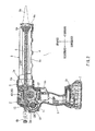
Fig. 2 is a vertical sectional view illustrating the internal structure of the caulking gun; -
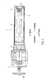
Fig. 3 is a plan view of the caulking gun as viewed in a direction indicated by arrow III inFig. 1 ; -
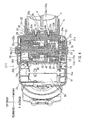
Fig. 4 is a cross-sectional view taken along line IV-IV inFig. 2 and showing a drive unit; -
Fig. 5 is an exploded perspective view of a transmission state switching device; -
Fig. 6 is a cross-sectional view of the transmission state switching device in a power transmission state; -
Fig. 7 is a cross-sectional view of the transmission state switching section in a transmission interruption state; -
Fig. 8 is a cross-sectional view similar toFig. 4 but showing a drive unit of a caulking gun according to an alternative embodiment; and -
Fig. 9 is an exploded perspective view of a transmission state switching device according to the alternative embodiment. - Each of the additional features and teachings disclosed above and below may be utilized separately or in conjunction with other features and teachings to provide improved caulking guns. Representative examples of the present invention, which examples utilize many of these additional features and teachings both separately and in conjunction with one another, will now be described in detail with reference to the attached drawings. This detailed description is merely intended to teach a person of skill in the art further details for practicing preferred aspects of the present teachings and is not intended to limit the scope of the invention. Only the claims define the scope of the claimed invention. Therefore, combinations of features and steps disclosed in the following detailed description may not be necessary to practice the invention in the broadest sense, and are instead taught merely to particularly describe representative examples of the invention. Moreover, various features of the representative examples and the dependent claims may be combined in ways that are not specifically enumerated in order to provide additional useful examples of the present teachings.
- In one embodiment, an electric caulking gun may include a cartridge setting portion to which a cartridge containing a caulking material can be set, an electric motor, a push rod driven by the electric motor via a power transmission path and configured to be pressed against the cartridge set at the cartridge setting portion to cause the caulking material to be dispensed from the cartridge, and a transmission state switching device provided in the power transmission path. The transmission state switching device may switch between a power transmission state in which the power transmission path is connected to transmit the power of the electric motor to the push rod, and a transmission interruption state in which the power transmission path is interrupted to permit the push rod to make a free movement independently of the rotation of the electric motor.
- With this arrangement, when the transmission state switching device is switched to the transmission interruption state, the push rod is separated from the power transmission path of the electric motor. Therefore, the push rod is allowed to make a free movement independent of the power of the electric motor with respect to both the advancing and retreating directions. When the push rod is placed in the state allowing free movement, it may retreat together with the extrusion surface of the cartridge due to the residual pressure inside the cartridge, whereby the residual pressure inside the cartridge is released. Hence, it is possible to prevent after-dripping.
- In this way, the push rod is separated from the power transmission path of the electric motor to be placed in a state in which it is freely movable, and the push rod retreats together with the extrusion surface of the cartridge as a result of the releasing of the residual pressure, so that no gap is generated between the extrusion surface of the cartridge and the distal end of the push rod. Therefore, over-restoration of the push rod cased by being forcibly retracted to an excessive degree through the reversing of the electric motor as in the related art, may not be caused, so that there is generated no time lag corresponding to the gap at the time of the next extrusion.
- The transmission state switching device may switch from the power transmission state to the transmission interruption state when the rotation of the electric motor is reversed. Therefore, the push rod is placed in the state in which it can move freely. Thereafter, the residual pressure inside the cartridge may push the push rod back. This means the push rod is not directly retracted by the reverse rotation the electric motor. Hence, over-restoration (i.e., production of a gap between the extrusion surface of the cartridge and the front end of the push rod) as in the related art may not be caused, and it is possible to avoid a time lag at the time of the next extrusion while preventing after-dripping.
- The transmission state switching device may include an upstream side transmission member provided on an upstream side in the power transmission path and having an outer circumferential surface with a plurality of flat transmission switching surfaces, a downstream side transmission member provided on a downstream side in the power transmission path and having an inner circumferential surface with a circular power transmission surface, and a plurality of power transmission pins each provided between each flat transmission switching surface and the circular power transmission surface. A distance between the power transmission surface and each transmission switching surface may change through relative displacement in a rotational direction of the upstream side transmission member with respect to the downstream side transmission member to switch between the power transmission state, in which each power transmission pin is clamped between the power transmission surface and each transmission switching surface, and the transmission interruption state in which the clamping of each power transmission pin is released to interrupt the power transmission path.
- With this arrangement, each power transmission pin provided between the transmission switching surface of the upstream side transmission member and each power transmission surface of the downstream side transmission member may be clamped or wedged between these surfaces, whereby the rotational power of the electric motor is transmitted to the push rod, and the caulking material may be dispensed from the cartridge. The clamping state of the power transmission pins may be released, for example, when the electric motor rotates in the reverse direction after it has been stopped. In this way, the power transmission state in which the downstream side transmission member is capable of relative rotation with respect to the upstream side transmission member may be achieved. Eventually, a state in which the push rod can retreat independently of the power of the electric motor (the state in which free movement is possible for the push rod) may be achieved. Therefore, the push rod may be moved to retreat by the residual pressure in the cartridge to release the residual pressure, thereby preventing after-dripping.
- In this way, retraction by the power obtained by reversing the electric motor as in the related art is not used. Instead, the push rod is placed in the state in which it is allowed to make free movement due to the switching of the transmission switching device to the power separation state. Then, the extrusion surface of the cartridge retreats due to the residual pressure therein, with the result that the extrusion surface retreats together with the push rod. Thus, no gap is generated between the front end of the push rod and the extrusion surface of the cartridge, so that time lag corresponding to the gap generated in the related art is not generated at the time of the next start of the electric motor. In this way, simultaneously with the next start of the electric motor, the extrusion surface of the cartridge may be pushed to dispense the caulking material, so that it is possible to improve the caulking gun in terms of usability and to realize a quick caulking material applying operation.
- Further, the transmission state switching device is switched between the power transmission state and the transmission interruption state through clamping (wedging) and releasing of the power transmission pins through relative rotation between the transmission switching surfaces and the power transmission surface. Therefore, as compared with the case where there is employed an engagement teeth type (cam type) clutch in which switching is effected between a power transmission state and a transmission interruption state through, for example, engagement and disengagement of engagement teeth, it is possible to effect switching between the power transmission state and the transmission interruption state in a shorter time. As a result, it is possible to shorten the time (i.e., the time lag) that elapses from the turning-on of the switch until the push rod starts to advance, which also helps to improve the caulking gun in terms of responsiveness.
- In one example, when the rotation of the electric motor is reversed, the transmission state switching device may be switched to the transmission interruption state to release the clamping of each power transmission pin, so that the reverse rotation of the electric motor is interrupted by the transmission state switching device.
- In this way, the transmission state switching device may function as a one-way clutch. At the time of normal rotation of the electric motor, the transmission state switching device may be switched to the power transmission state to transmit the rotational power to the push rod. On the other hand, when the electric motor is reversed, the transmission state switching device may be switched to the transmission interruption state, where the push rod is separated from the power transmission path and allowed to make free movement. Even in the case that the electric motor continues to be rotated in the reverse direction, the rotational power thereof may not be transmitted to the push rod, thus resulting in an idling state. The push rod separated from the power transmission path and placed in the state in which it can make free movement, may be pushed back by the residual pressure in the cartridge. Thus, the push rod is not restored to a degree more than necessary, and the front end thereof is maintained in the state in which it is held in contact with the extrusion surface of the cartridge, so that it is possible to avoid generation of a time lag at the time of the next start while reliably releasing the residual pressure of the cartridge to prevent after-dripping.
- The power transmission path may include a rotary member rotatable with the movement of the push rod when the power transmission state switch device is in the transmission interruption state. The caulking gun further include a rotational resistance applying device configured to apply a rotational resistance force to the rotary member.
- Thus, in the case that the power state switch device is in the transmission interruption state to allow free movement of the push rod, the rotational resistance applying device may apply the rotational resistance force to the rotary member. Therefore, although the push rod is free to move, an adequate resistance force may be applied to the push rod against its movement. In this way, for example, even in the case that the caulking gun is brought to an upwardly oriented position, the resistance force applied to the push rod may prevent the push rod from accidentally moving downward by the gravity force. Hence, it may be possible to reliably hold the push rod in a state where its front end is in contact with the extrusion surface of the cartridge. As a result, it is possible to further reliably eliminate potential time lag of movement of the push rod at the time of the next extrusion.
- Further, because the resistance force is indirectly applied to the push rod via the rotary member, a smaller resistance force against rotation of the rotary member may produce an adequate resistance force against movement of the push rod in comparison with the arrangement where a resistance against movement is directly applied to the
push rod 6. As a result, the caulking gun having the rotational resistance applying device can be configured to have a simple and compact construction. - The rotary member to which the resistance force is applied by the resistance force applying device may be the downstream side transmission member.
- The rotational resistance force may be a magnetic attracting force. In such a case, the rotational resistance applying device may be a magnet. The magnet can apply an adequate rotational resistance force to the rotary member without leading to a complicated construction of the caulking gun.
- An embodiment of the present invention will now be described with reference to
Figs. 1 through 7 .Figs. 1 through 3 show anelectric caulking gun 1 according to the present embodiment. Thecaulking gun 1 may generally include amain body portion 2 having anelectric motor 10 disposed therein for serving as a drive source, acartridge setting portion 4, through which acartridge 3 accommodating a caulking material can be set, and ahandle portion 5 to be grasped by the user. - The
cartridge setting portion 4 is disposed at the front portion of themain body portion 2 so as to protrude forward therefrom. Thecartridge setting portion 4 may have a semi-cylindrical tubular shape for holding thecartridge 3 from below, so that anozzle 3a of thecartridge 3 may protrude forward from afront end portion 4a of thecartridge setting portion 4. Thecartridge setting portion 4 can be detached from themain body portion 2 by loosening a threaded fixingsleeve 8. - A
push rod 6 may protrude forward from the front portion of themain body portion 2. Thispush rod 6 is movable in forward and rearward directions within thecartridge setting portion 4. At the front end of thispush rod 6, there is provided apush plate 6a to be pressed against anextrusion surface 3b of thecartridge 3. Referring toFig. 2 , thepush rod 6 can move between a front stroke end and a rear stroke end, where thepush plate 6a is positioned as indicated by solid lines and chain double-dashed lines, respectively, as shown inFig. 2 . The rear end portion of thepush rod 6 may protrude rearwards from themain body portion 2. Agrip 6b may be provided at the rear end portion and can be grasped by the user for pulling thepush rod 6. On the lower surface of thepush rod 6, there is provided arack portion 6c extending along the longitudinal direction thereof. Thisrack portion 6c may mesh with adrive gear 40 that will be described later. In a power transmission state, thepush rod 6 advances via a power transmission mechanism including a rack/pinion mechanism formed by therack portion 6c and thedrive gear 40. - The
handle portion 5 is provided so as to protrude downwardly from the lower portion of themain body portion 2. On the front side of the base portion of thehandle portion 5, there is provided aswitch lever 5a to be pulled by a fingertip of the hand of the user grasping thehandle portion 5. When theswitch lever 5a is pulled (i.e., turned on), anelectric motor 10 provided inside themain body portion 2 starts to rotate in a normal direction. When the pulling operation is released (i.e., turning-off operation is performed), theelectric motor 10 stops after being slightly rotated in a reverse direction. Abattery attachment portion 5b is provided at the lower end portion of thehandle portion 5. Abattery pack 7 may be attached to thebattery attachment portion 5b. Theelectric motor 10 rotates with a supply of power from thebattery pack 7. Thebattery pack 7 may be a rechargeable batter and may be repeatedly used by being detached from thebattery attachment portion 5b and recharged by a charger separately prepared. -
Fig. 4 shows the internal structure of themain body portion 2. Theelectric motor 10 may be disposed within a rear portion of amain body housing 2a of themain body portion 2. Adrive pulley 11 may be mounted to anoutput shaft 10a of theelectric motor 10. Areduction gear mechanism 20 is disposed on the front side of theelectric motor 10. Aninput shaft 21 of thereduction gear mechanism 20 is arranged so as to be rotatable about an axis J that may be parallel to theoutput shaft 10a of theelectric motor 10. A drivenpulley 22 having a larger diameter than thedrive pulley 11 may be mounted to theinput shaft 21. Atransmission belt 12 may extend between thedrive pulley 11 and the drivenpulley 22. Due to this belt transmission mechanism, the rotational power of theelectric motor 10 is reduced at a fixed reduction ratio before being input to thereduction gear mechanism 20. - The
reduction gear mechanism 20 may include a first stageplanetary gear train 23, a second stageplanetary gear train 24, a third stageplanetary gear train 25, and a transmissionstate switching device 30. Theinput shaft 21 is rotatably supported by the right-hand side portion of amain body housing 2a via abearing 2b and is also rotatably supported by the right-hand side portion of ahousing cover 20e via abearing 20b. On thisinput shaft 21, there is formed a first-stage sun gear 21a of the first-stageplanetary gear train 23. Three first-stageplanetary gears 23a are in mesh with the first-stage sun gear 21a. Each first-stageplanetary gear 23a is in mesh with a right-hand sideinternal gear 20c mounted within the right-hand side portion of agear housing 20a. The three first-stageplanetary gears 23a are rotatably supported by a first-stage carrier 23b. A second-stage sun gear 23c of the second-stageplanetary gear train 24 is formed on the first-stage carrier 23b. The three second-stageplanetary gears 24a are in mesh with the second-stage sun gear 23c. The second-stageplanetary gears 24a are also in mesh with the above-mentioned right-hand sideinternal gear 20c. The three second-stageplanetary gears 24a are rotatably supported by a second-stage carrier 24b. Adrive shaft 26 is connected to the second-stage carrier 24b. In this way, the rotational power of theelectric motor 10 reduced by the belt transmission mechanism is further reduced by the above-mentioned first-stage and second-stageplanetary gear trains drive shaft 26. - The
drive shaft 26 is arranged on the same axis as theinput shaft 21. Accordingly, thedrive shaft 26 is rotatable about the axis J that is parallel to theoutput shaft 10a (rotational axis) of theelectric motor 10. Thedrive shaft 26 extends to the left-hand side portion within themain body portion 2. The left-hand side end portion of thedrive shaft 26 is rotatably supported by themain body housing 2a via abearing 27. A third-stage sun gear 26a of the thirdplanetary gear train 25 is formed on the left-hand end portion of thedrive shaft 26. The three third-stageplanetary gears 25a are in mesh with the third-stage sun gear 26a. Each third-stageplanetary gear 25a is in mesh with a left-hand sideinternal gear 20d mounted within the left-hand side portion of thegear housing 20a. The three third-stageplanetary gears 25a are rotatably supported by a third-stage carrier 25b. - In this way, the rotational power of the
drive shaft 26 is further reduced by the third-stageplanetary gear train 25 before being input to the transmissionstate switching device 30. As shown in the drawing, this transmissionstate switching device 30 is coaxial with thedrive shaft 26, and is positioned substantially centrally with respect to the right and left widthwise direction of themain body portion 2. When the drive shat 26 or theelectric motor 10 rotates in a normal direction, the rotational force may be transmitted to thedrive gear 40 via the transmissionstate switching device 30, so that thepush rod 6 in mesh with thedrive gear 40 moves forward. - Here, the transmission path for the rotational power from the
electric motor 10 to thedrive gear 40 will be described. First, at the right-hand end portion of themain body portion 2, the rotational power is input to theinput shaft 21 via the belt transmission type reduction mechanism. The rotational power input to theinput shaft 21 is output to thedrive shaft 26 via the first-stage and second-stage gear trains drive shaft 26 is input to the third-stageplanetary gear train 25. Regarding the third-stageplanetary gear train 25, the orientation with respect to the right and left direction thereof (the positional relationship of the third-stage carrier 25b with respect to the third-stage sun gear 26a) is opposite that of the first-stage and second-stageplanetary gear trains planetary gear row 25 is transmitted to thedrive gear 40 via the transmissionstate switching device 30. - In this way, the transmission path of the rotational power of the
electric motor 10 input from the right-hand end side of themain body portion 2 is oriented from the right-hand end side of themain body portion 2 to the left-hand end side thereof, and the orientation is then reversed to return to the center with respect to the right and left widthwise direction of themain body portion 2 for transmission to thedrive gear 40, thus forming a J-shaped transmission path. With this transmission path for the rotational power, it is possible to arrange a larger number of stages of reduction gear trains (planetary gear train) on the axis J, and to obtain a large reduction ratio while achieving a reduction in the size in the widthwise direction of themain body portion 2. Further, it is possible to arrange thepush rod 6 across the center with respect to the widthwise direction of themain body portion 2. -
Figs. 5 through 7 illustrate the transmissionstate switching device 30 in detail. The transmissionstate switching device 30 may include an upstreamside transmission member 31, a downstreamside transmission member 32 and a plurality of power transmission pins 33 provided between the upstreamside transmission member 31 and the downstreamside transmission member 32. The upstreamside transmission member 31 may be disposed coaxially and integrally with the third-stage carrier 25b that is an upstream side member with respect to the power transmission path. The downstreamside transmission member 32 may be formed integrally with on thedrive gear 40. - The upstream
side transmission member 31 may be formed as a nonagon prism shape having nine flattransmission switching surfaces 31a formed on the outer peripheral surface thereof. Eachtransmission switching surface 31a is in contact with onepower transmission pin 33. Apin holder 34 may retain the nine power transmission pins 33 at substantially equal intervals along a circle. As shown in the drawing, thepin holder 34 is integrally provided with a total of ninesupport pillars 34c arranged along a circle. The ninesupport pillars 34c extend parallel to each other in the direction of the axis J. Onepower transmission pin 33 is retained between twoadjacent support pillars 34c so as to be capable of displacement in the radial direction of thepin holder 34. Three engagement recesses 34b are formed in aflange portion 34a of thepin holder 34. The threeengagement recesses 34b are arranged at three positions that are at equal intervals in the circumferential direction. In correspondence with the threeengagement recesses 34b, there are provided threeengagement protrusions 31b on the right-hand end surface of the third-stage carrier 25b. When the threeengagement protrusions 31b are respectively moved into the engagement recesses 34b, theflange portion 34a may contact with the right-hand side surface of the third-stage carrier 25b, whereby the nine power transmission pins 33 are arranged at equal intervals in the circumferential direction on the outer peripheral side of the upstreamside transmission member 31 through the intermediation of thepin holder 34. - Within a movable range of the
engagement protrusions 31b relative to and within the engagement recesses 34b, the upstreamside transmission member 31 is capable of relative rotation with respect to thepin holder 34. As a result of the relative rotation of the upstreamside transmission member 31 with respect to thepin holder 34, eachtransmission switching surface 31a is displaced in the circumferential direction with respect to eachpower transmission pin 33. - A
rubber ring 28 having an annular configuration may slidably contact the outer circumferential surface of the third-stage carrier 25b. Therubber ring 28 may be fixed in position along the inner circumferential surface of thegear housing 20a. As a result of the sliding contact of therubber ring 28 with the circumferential surface of the third-stage carrier 25b, an appropriate frictional resistance against rotation in the rotational direction of the third-stage carrier 25b may be produced. Due to this appropriate resistance, the rotational position of the third-stage carrier 25b is maintained when theelectric motor 10 is at rest (i.e., in the rotation-free state). - Each
power transmission pin 33 may be retained between thetransmission switching surface 31a of the upstreamside transmission member 31 and the inner circumferential surface (power transmission surface 32a) of the downstreamside transmission member 32. Thus, when eachtransmission switching surface 31a is displaced in the circumferential direction with respect to eachpower transmission pin 33 through the relative rotation of the upstreamside transmission member 31 with respect to thepin holder 34, the distance between thepower transmission surface 32a of the downstreamside transmission member 32 and eachtransmission switching surface 31a of the upstreamside transmission member 31 may be changed. - As the upstream
side transmission member 31 makes relative displacement with respect to thepin holder 34 in the normal rotational direction (clockwise as seen inFig. 6 ) as indicated by outline arrow A inFig. 6 by the on-operation of theswitch lever 5a, the distance between thepower transmission surface 32a of the downstreamside transmission member 32 and eachtransmission switching surface 31a of the upstreamside transmission member 31 may be reduced with respect to eachpower transmission pin 33. As the distance between thesurfaces surfaces surfaces side transmission member 31 to the downstreamside transmission member 32. As shown inFig. 6 , at this stage, theengagement protrusions 31b are not in contact with the end portions of the engagement recesses 34b, so that the rotational power of the upstreamside transmission member 31 can be reliably transmitted to the downstreamside transmission member 32 by way of engagement of the power transmission pins 33. - In contrast, when the
switch lever 5a is operated to be switched off, theelectric motor 10 may be stopped after being slightly rotated in the reverse direction. As shown inFig. 7 , as theelectric motor 10 is slightly rotated in the reverse direction, the upstreamside transmission member 31 makes relative displacement in the reverse direction (in the counterclockwise direction as viewed inFig. 7 ) indicated by outline arrow B with respect to thepin holder 34, and the distance between thepower transmission surface 32a and thetransmission switching surface 31a becomes maximum with respect to eachpower transmission pin 33. When the distance between thesurfaces surfaces side transmission member 31 to the downstreamside transmission member 32. As shown inFig. 7 , at this stage, theengagement protrusions 31b may contact with the end portions of the engagement recesses 34b, so that the relative rotation in the reverse direction of the upstreamside transmission member 31 with respect to thepin holder 34 can be restricted. In this state, eachpower transmission pin 33 is situated at the center of thetransmission switching surface 31a, so that the distance between thetransmission switching surface 31a and thepower transmission surface 32a may be a maximum distance. Thus, the clamping state of the power transmission pins 33 is kept released, so that the transmission interruption state is maintained. This transmission interruption state of the transmissionstate switching device 30 may be maintained even after theelectric motor 10 has been stopped. - As described above, the
rubber ring 28 is in sliding contact with the circumferential surface of the third-stage carrier 25b to maintain the rotational position thereof. Therefore, the rotation stop position of the third-stage carrier 25b and eventually that of the upstreamside transmission member 31 may be maintained when theelectric motor 10 has been stopped. This may also help to reliably maintain the transmission interruption state when theelectric motor 10 has been stopped. - In this way, as the upstream
side transmission member 31 makes relative rotation in the normal direction indicated by the outline arrow A inFig. 6 through the normal rotation of theelectric motor 10, the transmissionstate switching device 30 may be brought to the power transmission state shown inFig. 6 , and the rotational power is transmitted to the downstreamside transmission member 32. As the upstreamside transmission member 31 makes relative rotation to the reverse direction as indicated by the outline arrow B inFig. 7 through slight rotation in the reverse direction of theelectric motor 10 as a result of the switching-off of theswitch lever 5a, the transmissionstate switching device 30 is brought to the transmission interruption state in which the transmission of power between the upstreamside transmission member 31 and the downstreamside transmission member 32 is interrupted. In this transmission interruption state, thepush rod 6 may be separated from the rotational power transmission path of theelectric motor 10 so as to be movable independently. Therefore, thepush rod 6 may be brought to a free-movement-possible state in which it can be advanced by pushing thegrip 6b manually forwards while grasping thegrip 6b and in which, conversely, it can be retreated by pulling thegrip 6b backwards. - The downstream
side transmission member 32 is rotatably supported by thegear housing 20a viabearings side transmission member 32 is also rotatable about the axis J. Thedrive gear 40 is provided on the outer circumferential surface of the downstreamside transmission member 32. As shown inFig. 4 , thedrive gear 40 is situated substantially at the center in the right and left widthwise direction of themain body portion 2. Thus, thepush rod 6 having therack portion 6c in mesh with thedrive gear 40 is arranged so as to be capable of advancing and retreating in the forward and rearward directions across substantially the center in the right and left widthwise direction of themain body portion 2. - In the transmission interruption state when the
electric motor 10 is at rest, thepush rod 6 is in the free-movement-possible state. In this free-movement-possible state, it is possible to restore thepush rod 6 backwards by grasping itsgrip 6b and pulling it manually backwards. When thepush rod 6 has been retreated by pulling it backwards, it is possible to place thecartridge 3 on thecartridge setting portion 4. After thecartridge 3 has been placed on thecartridge setting portion 4, thepush rod 6 in the free-movement-possible state is manually pushed forwards, and thepush plate 6a thereof is brought into contact with theextrusion surface 3b of thecartridge 3. In this way, the setting of thecartridge 3 is completed. - When the user pulls the
switch lever 5a with a fingertip of his or her hand grasping thehandle portion 5, theelectric motor 10 is started to rotate in the normal direction. The rotation of theelectric motor 10 is reduced by the belt reduction mechanism formed by thedrive pulley 11 and the drivenpulley 22 between which thetransmission belt 12 extends, and is then input to thereduction gear mechanism 20 to be further reduced. By thereduction gear mechanism 20, the rotation of theelectric motor 10 is further reduced by the first through third-stageplanetary gear trains 23 through 25. The rotation reduced by the first-stage and second-stageplanetary gear trains main body portion 2 is input to the third-stageplanetary gear train 25 arranged on the left-hand side portion of themain body portion 2 via thedrive shaft 26. After being reduced by the third-stageplanetary gear train 25, the rotational power is input to the transmissionstate switching device 30 arranged substantially at the center in the right and left widthwise direction of themain body portion 2. - As long as the
electric motor 10 rotates in the normal direction, a power transmission state is achieved by the transmissionstate switching device 30, in which the power transmission pins 33 are clamped and wedged between the transmission switching surfaces 31a of the upstreamside transmission member 31 and thepower transmission surface 32a of the downstreamside transmission member 32. Due to this power transmission state, the rotational power of theelectric motor 10 is output to thedrive gear 40. As thedrive gear 40 is rotated by the rotational power, thepush rod 6 advances trough the mesh-engagement between thedrive gear 40 and therack portion 6c. As thepush rod 6 advances, theextrusion surface 3b of thecartridge 3 is pushed in the dispensing direction by itspush plate 6b, so that the caulking material contained in thecartridge 3 is dispensed from thenozzle 3a. - After a fixed amount of caulking material has been dispensed from the
nozzle 3a, the user may release the pulling force of theswitch lever 5a (i.e., performs turning-off operation), so that theelectric motor 10 stops after being slightly reversed. As theelectric motor 10 is reversed, the transmissionstate switching device 30 is switched to the transmission interruption state shown inFig. 7 as described above. In the transmission interruption state, thepush rod 6 is separated from the power transmission path of theelectric motor 10, and is placed in the free-movement-possible state. When thepush rod 6 is placed in the free-movement-possible state, thepush rod 6 may be pushed backwards together with theextrusion surface 3b due to the residual pressure inside thecartridge 3, whereby it is possible to prevent so-called after-dripping from thenozzle 3a. - With the
caulking gun 1 of this embodiment constructed as described above, there is provided, in the power transmission path between theelectric motor 10 and thepush rod 6, the transmissionstate switching device 30 capable of switching between the power transmission state shown inFig. 6 and the transmission interruption state shown inFig. 7 . This transmissionstate switching device 30 is forcibly switched to the transmission interruption state through slight reversing of theelectric motor 10 as a result of the turning-off of theswitch lever 5a. - As the transmission
state switching device 30 is switched to the transmission interruption state, thepush rod 6 is separated from the power transmission path of theelectric motor 10, and is placed in the free-movement-possible state. When thepush rod 6 is placed in the free-movement-possible state, thepush rod 6 is retreated by the residual pressure inside thecartridge 3, whereby the residual pressure inside thecartridge 3 is released, making it possible to prevent after-dripping. - In this way, through the turning-off of the
switch lever 5a, theelectric motor 10 is slightly reversed, and the transmissionstate switching device 30 is switched to the transmission interruption state, thereby placing thepush rod 6 in the free-movement-possible state. As a result, thepush rod 6 is pushed back by the residual pressure of thecartridge 3, whereby the residual pressure inside thecartridge 3 is released. Thus, no gap may be generated between theextrusion surface 3b of thecartridge 3 and thepush plate 6a of thepush rod 6, so that over-restoration in which the push rod is forcibly retreated through the reverse rotation of the electric motor as in the conventional construction may not occur. Therefore, time lag corresponding to the gap in the conventional construction at the time of the next extrusion may not be produced. - The relative rotational angle in the reverse direction of the upstream
side transmission member 31 with respect to thepin holder 34 may be restricted to a fixed angle through interference of theengagement protrusions 31b with the engagement recesses 34b as shown inFig. 7 . Thus, the reverse rotation of theelectric motor 10 may not cause clamping of the power transmission pins 33 of the transmissionstate switching device 30, so that the upstreamside transmission member 31 and the downstreamside transmission member 32 may not be rotated together in the reverse direction. Thus, the rotation in the reverse direction of theelectric motor 10 is not transmitted to the downstreamside transmission member 32. In this way, theelectric motor 10 rotates idle in the reverse direction after the transmissionstate switching device 30 has been switched to the transmission interruption state. No manual operation is necessary for the switching operation of the transmissionstate switching device 30. - Accordingly, independently of the time of reversing the rotation of the
electric motor 10, thepush rod 6 may not retreat by a distance more than necessary for releasing the residual pressure (over-restoration in the related-art technique). Therefore, thepush plate 6a may be held in contact with theextrusion surface 3b of thecartridge 3, so that time lag corresponding to the gap may not occur at the time of the next extrusion operation. - In this way, the
push rod 6 is not directly retreated by the rotation of theelectric motor 10 as in the related art but is retreated together with theextrusion surface 3b due to the residual pressure in thecartridge 3 in the free-movement-possible state, which is realized by placing the transmissionstate switching device 30 in the transmission interruption state. No gap is generated between the front end of the push rod 6 (thepush plate 6a) and theextrusion surface 3b of thecartridge 3. Thus, time lag corresponding to the gap as in the elated art may not be generated at the time of the next starting of the electric motor (which means a satisfactory responsiveness), and theextrusion surface 3b of thecartridge 3 is pressed substantially simultaneously to dispense the caulking material, so that it is possible to improve thecaulking gun 1 in terms of usability, and to realize a quick caulking material applying operation. - Further, in the embodiment described above, the belt transmission type reduction mechanism is provided between the
output shaft 10a of theelectric motor 10 and thereduction gear mechanism 20. As compared with the gear mesh-engagement type reduction mechanism, the belt transmission type reduction mechanism can provide a higher reduction ratio without involving an increase in the distance between theoutput shaft 10a of theelectric motor 10 and thedrive shaft 26, so that it is possible to achieve a reduction in the size, mainly in the forward and rearward direction, of themain body portion 2 and eventually the size of thecaulking gun 1. - The above-described embodiment may be modified in various ways. For example, while in the above embodiment the rotation of the
electric motor 10 is reduced by the belt transmission mechanism in which thetransmission belt 12 extends between thedrive pulley 11 and the drivenpulley 22, the reduction may be effected through mesh-engagement of gears. - Further, while in the above embodiment three stages of
planetary gear trains 23 through 25 are provided in thereduction gear mechanism 20, the reduction may also be effected by one or two stages of planetary gear trains; or, conversely, by four or more stages of planetary gear trains. In this case, it is possible to effect the reduction by providing one or two stages of planetary gear trains respectively on both sides of themain body portion 2. - Further, while in the above-described embodiment nine power transmission pins 33 are provided in the transmission
state switching device 30, it is also possible to attain the same effect by providing the power transmission pins in a number not more than eight or in a number not less than ten. - Further, while in the above-described embodiment the electric motor 10 (the
output shaft 10a thereof) is arranged parallel to thedrive shaft 26, even in a case where it is arranged orthogonal to the drive shaft or arranged otherwise, it is possible to attain the same effect by using the above-described transmissionstate switching device 30. - Further, while in the above-described embodiment the engagement (wedging) of the transmission pins 33 is released by slightly reversing the
electric motor 10 after the turning-off of theswitch lever 5a to cause the upstreamside transmission member 31 to make relative rotation in the direction indicated by the outline arrow B inFig. 7 with respect to thepin holder 34. However, it is also possible to apply an external force to thepin holder 34 for releasing the engagement of the transmission pins 33 by providing, for example, between the upstreamside transmission member 31 and thepin holder 34, a biasing device such as a torsion spring for imparting an biasing force for causing thepin holder 34 to make relative rotation clockwise as seen inFig. 6 with respect to the upstreamside transmission member 31. In such a construction, when theelectric motor 10 is stopped by turning off theswitch lever 5a to thereby release the rotational power for the upstreamside transmission member 31, thepin holder 34 may make relative rotation by a fixed angle in the same direction as that indicated by the outline arrow A inFig. 6 with respect to the upstreamside transmission member 31 due to the above-mentioned biasing force to thereby release the engagement of the transmission pins 33, with the result that the transmission state switching device is switched to the power separation state shown inFig. 7 . In this way, by using the biasing device, it is no longer necessary for rotating theelectric motor 10 in the reverse direction after the turning-off of theswitch lever 5a. In addition, no manual operation is necessary for the switching operation of the transmissionstate switching device 30. - Also in the case in which the above biasing device is employed, the relative rotation angle in the engaging releasing direction in which the engagement of the
pin holder 34 with the upstreamside transmission member 31 is released, is restricted to a fixed angle through interference of theengagement protrusions 31b with the engagement recesses 34b as in the above-described embodiment. - Further, although the
push rod 6 is free to move when thepower transmission portion 30 is in the transmission interruption state, it may be possible to apply a resistance force against movement of thepush rod 6. In a caulking gun according to an alternative embodiment shown inFigs. 8 and9 , amagnet 41 is provided for applying a rotational resistance force to the downstreamside transmission member 32 and eventually applying a movement resistance force to thepush rod 6. The caulking gun according to the alternative embodiment shown inFigs. 8 and9 is different from thecaulking gun 1 of above embodiment in that themagnet 41 is provided and that aretainer hole 20f for retaining themagnet 41 is formed in thegear housing 20a. In other respect, the construction is the same as thecaulking gun 1 of the above embodiment. Therefore, inFigs. 8 and9 , like members are given the same reference numerals as the embodiment shown inFIGS. 1 to 7 and the description of these members will not be repeated. - As described in connection with the above embodiment, when the transmission
state switching device 30 is switched to the transmission interruption state, thepush rod 6 may be separated from the power transmission path of theelectric motor 10 so as to be capable of being freely moved. In the embodiment shown inFigs. 8 and9 , a fixed resistance force may be applied to thepush rod 6 against the free movement of thepush rod 6. - More specifically, the
magnet 41 may be located at a position laterally outer side of the downstreamside transmission member 32. Themagnet 41 may be a permanent magnet having a cylindrical rod-like shape. Themagnet 41 may be press-fitted into theretainer hole 20f formed in thegear housing 20a so as to be retained therein. Accidental removal of themagnet 41 from theretainer hole 20f may be prevented, for example, by a part of thebody housing 2a that may serve as a closure member for theretainer hole 20f. Preferably, themagnet 41 may be retained at a position spaced from the outer circumferential surface of the downstreamside transmission member 32 by a small gap. The downstreamside transmission member 32 may be made of magnetically attractable metal, such as steel. Due to the magnetic attractive force of themagnet 41, an adequate rotational resistance may be applied against the rotation of the downstreamside transmission member 32. - In this way, the
magnet 41 may serve as a rotational resistance applying member that applies a given rotational resistance against rotation of the downstreamside transmission member 32. Therefore, an adequate movement resistance may be applied to thepush rod 6 even after thepush rod 6 has been brought to be free to move by the operation of the transmissionstate switching device 30. Thus, although thepush rod 6 is separated from the power transmission path of theelectric motor 10 so as to be free to move (for example, by the manual operation by the user), the adequate movement resistance force may be applied indirectly to thepush rod 6 by themagnet 41. The movement resistance force may prevent thepush rod 6 from accidentally moving downward by the gravity force, for example, when the user grasps the caulking gun in an upwardly oriented position with thecartridge setting portion 4 oriented upward. It may be also possible to prevent thepush rod 6 from accidentally retracting by the inertia force that may be produced due to vibrations or the like applied to the caulking gun. Therefore, even though thepush rod 6 is free to move by the manual operation, it may be possible to reliably hold thepush rod 6 in a state where itspush plate 6a is in contact with theextrusion surface 3b of thecartridge 3. As a result, it is possible to further reliably eliminate potential time lag of movement of thepush rod 6 at the time of the next extrusion. - Further, in this alternative embodiment, the
magnet 41 is located at a position laterally outer side of the outer circumferential surface of the downstreamside transmission member 32 with which thedrive gear 40 for meshing with therack 6c of thepush rod 6 is integrally formed. In other words, the resistance against movement of thepush rod 6 is not directly applied to thepush rod 6 but is applied to a rotary member that rotates with the free movement of thepush rod 6. - In comparison with the arrangement where a resistance against movement is directly applied to the
push rod 6, a smaller resistance force against rotation of the rotary member may produce an adequate resistance force against movement of thepush rod 6. Hence, it is possible to use a simple and small element (magnet 41 in this embodiment) as a rotational resistance applying member. As a result, the caulking gun having a rotational resistance applying device can be configured to have a compact construction. - Further, the
magnet 41 as the rotational resistance applying member is located on the lateral side of the downstream side transmission member 32 (i.e., the rotary member), it is possible to easily replace themagnet 41 with another one. By replacing themagnet 41 with another magnet that can apply a different resistance force against rotation of the rotary member, it is possible to set a movement resistance force best suited to thepush rod 6 used in the caulking gun. - Furthermore, in this embodiment, the resistance force is not directly applied to the
push rod 6 from a lateral side, for example, by using a biasing member. Instead, the resistance force is applied to the rotary member that is a separate member from thepush rod 6. Therefore, the resistance force may not cause an undesirable shifting movement of thepush rod 6 in the lateral direction. Hence, it is possible to avoid degradation in the durability of the caulking gun. - The above alternative embodiment may be further modified. For example, although the
magnet 41 is attached to thegear housing 20, themagnet 41 may be attached to any other portion around the downstream side transmission member 32 (i.e., the rotary member) as long as it can resist against rotation of the downstreamside transmission member 32 about the axis J. - Further, although the resistance force against rotation is applied to the downstream
side transmission member 32 that is integrated with thedrive gear 40, the resistance force may be applied to thedrive gear 40. In other words, it may be possible to apply the resistance force to any of rotary members in the power transmission path, which may rotate with the movement of thepush rod 6. - Further although the
magnet 41 is located to be opposed to the outer circumferential surface of the downstream side transmission member 32 (i.e., the rotary member), themagnet 41 may be located to be opposed to a side surface of the downstreamside transmission member 32 in the axial direction. In addition, themagnet 41 may be attached to the downstreamside transmission member 32 in place of thegear housing 20a. It may be also possible to provide two ormore magnets 41. - Further, the
magnet 41 may be replaced with any other rotational resistance applying member, such as a rubber ring slidably contacting with the entire circumference of the rotary member, a resilient member such as a rubber strip and a spring, or a fabric such as a cloth and a felt material frictionally contacting the circumferential surface or the side surface of the rotary member for applying a frictional resistance against rotation. - It is explicitly stated that all features disclosed in the description and/or the claims are intended to be disclosed separately and independently from each other for the purpose of original disclosure as well as for the purpose of restricting the claimed invention independent of the composition of the features in the embodiments and/or the claims. It is explicitly stated that all value ranges or indications of groups of entities disclose every possible intermediate value or intermediate entity for the purpose of original disclosure as well as for the purpose of restricting the claimed invention, in particular as limits of value ranges.
Claims (15)
- An electric caulking gun (1) comprising:a cartridge setting portion (4) to which a cartridge (3) containing a caulking material can be set;an electric motor (10);a push rod (6) driven by the electric motor (10) via a power transmission path and configured to be pressed against the cartridge (3) for dispensing the caulking material from the cartridge (3), andan interruption device (30) operable for interrupting the power transmission path and allowing the push rod (6) to be freely moved.
- The electric caulking gun (1) according to claim 1, wherein the interruption device (30) interrupts the power transmission path immediately after a given amount of the caulking material has been dispensed from the cartridge (3).
- The electric caulking gun (1) according to claim 1 or 2, wherein:The interruption device (30) comprises a transmission state switching device (30) configured to switch between a power transmission state in which the power transmission path is connected to transmit the power of the electric motor (10) to the push rod (6), and a transmission interruption state in which the power transmission path is interrupted to permit the push rod (6) to make a free movement independently of the rotation of the electric motor (10).
- The caulking gun (1) according to claim 3, wherein the transmission state switching device (30) is switched from the power transmission state to the transmission interruption state by a reverse rotation of the electric motor (10).
- The caulking gun (1) according to claim 3 or 4, wherein the transmission state switching device (30) comprises:an upstream side transmission member (31) provided on an upstream side in the power transmission path and having an outer circumferential surface with a plurality of flat transmission switching surfaces (31a);a downstream side transmission member (32) provided on a downstream side in the power transmission path and having an inner circumferential surface with a circular power transmission surface (32a), anda plurality of power transmission pins (33) each provided between each flat transmission switching surface (31a) and the circular power transmission surface (32a)wherein a distance between the power transmission surface (32a) and each transmission switching surface (31a) changes through relative displacement in a rotational direction of the upstream side transmission member (31) with respect to the downstream side transmission member (32) to switch between the power transmission state, in which each power transmission pin (33) is clamped between the power transmission surface (32a) and each transmission switching surface (31a), and the transmission interruption state in which the clamping of each power transmission pin (33) is released to interrupt the power transmission path.
- The caulking gun (1) according to claim 5, wherein when the rotation of the electric motor (10) is reversed, the transmission state switching device (30) is switched to the transmission interruption state to release the clamping of each power transmission pin (33), so that the reverse rotation of the electric motor (10) is interrupted by the transmission state switching device (30).
- The caulking gun (1) according to claim 5 or 6, further comprising a pin holder (34) having a plurality of pillar portions (34c) for holding the power transmission pins (33) such that each power transmission pin (33) can move between the power transmission surface (32a) and each transmission switching surface (31a) in a radial direction of the pin holder (34).
- The caulking gun (1) according to claim 7, wherein the pin holder (34) is rotatable relative to the upstream side transmission member (31) within a predetermined range.
- The caulking gun (1) according to any one of claims 3 to 8, further comprising a reduction mechanism (11, 12, 22, 20) provided in the power transmission path on the upstream side of the transmission state switching device (30).
- The electric caulking gun (1) according to any one of the preceding claims, wherein:the power transmission path includes a rotary member (32, 40) rotatable with the movement of the push rod (6) when the power transmission path is interrupted;the caulking gun (1) further includes a rotational resistance applying device (41) configured to apply a rotational resistance force to the rotary member (32, 40).
- The electric caulking gun (1) according to claim 10, wherein the rotational resistance force is a magnetic attracting force or a frictional force.
- The electric caulking gun (1) according to claim 10 or 11, wherein the rotational resistance applying device is a magnet (41).
- The electric caulking gun (1) according to any one of claims 10 to 12 as depending from claims 5 to 9, wherein the rotary member is the downstream side transmission member (32).
- The electric caulking gun (1) according to any one of claims 10 to 12, wherein the transmission path includes a drive gear (40) coupled to the electric motor (10), and a rack (6c) provided on the push rod (6) and meshing with the drive gear (40); and
the rotary member is the drive gear (40). - The electric caulking gun (1) according to any one of claims 10 to 14, wherein the rotational resistance applying device (41) applies the rotational resistance force to the rotary member (32, 40) as long as the power transmission path is in the transmission interruption state.
Applications Claiming Priority (2)
| Application Number | Priority Date | Filing Date | Title |
|---|---|---|---|
| JP2012051434A JP6017153B2 (en) | 2012-03-08 | 2012-03-08 | Caulking gun |
| JP2012142856A JP5996296B2 (en) | 2012-06-26 | 2012-06-26 | Caulking gun |
Publications (2)
| Publication Number | Publication Date |
|---|---|
| EP2636456A1 true EP2636456A1 (en) | 2013-09-11 |
| EP2636456B1 EP2636456B1 (en) | 2015-04-15 |
Family
ID=47754342
Family Applications (1)
| Application Number | Title | Priority Date | Filing Date |
|---|---|---|---|
| EP13156732.3A Active EP2636456B1 (en) | 2012-03-08 | 2013-02-26 | Caulking guns |
Country Status (3)
| Country | Link |
|---|---|
| US (1) | US8998039B2 (en) |
| EP (1) | EP2636456B1 (en) |
| RU (1) | RU2013108453A (en) |
Cited By (1)
| Publication number | Priority date | Publication date | Assignee | Title |
|---|---|---|---|---|
| CN114809543A (en) * | 2022-05-14 | 2022-07-29 | 赵潇 | Auxiliary filling equipment for ceramic tile gap |
Families Citing this family (12)
| Publication number | Priority date | Publication date | Assignee | Title |
|---|---|---|---|---|
| US9723845B2 (en) * | 2014-12-12 | 2017-08-08 | Helen Of Troy Limited | Dispensing gun |
| CN104652796A (en) * | 2015-02-02 | 2015-05-27 | 博艳萍 | Floor tile caulking machine |
| CN106150050B (en) * | 2016-07-11 | 2018-07-13 | 北京东豪建设集团有限公司 | A kind of uniform mopping device for building |
| US10766053B2 (en) | 2017-01-04 | 2020-09-08 | Red Devil, Inc. | Material dispensing system and method |
| USD872547S1 (en) * | 2017-08-17 | 2020-01-14 | Sulzer Mixpac Ag | Discharge device |
| TW201932201A (en) * | 2018-01-15 | 2019-08-16 | 朱益民 | Glue gun device |
| US10272466B1 (en) * | 2018-02-13 | 2019-04-30 | Siang Syuan Fu Enterprise Co., Ltd. | Caulking gun |
| TWI649131B (en) * | 2018-04-11 | 2019-02-01 | 何炳梓 | Glue gun drive |
| WO2021248241A1 (en) | 2020-06-09 | 2021-12-16 | Groupe Refraco Inc. | Mortar applicator and mortar application system having same |
| DE202020104650U1 (en) | 2020-08-11 | 2021-11-12 | Marco Roth | Device for dispensing at least one pasty mass |
| USD995243S1 (en) * | 2021-06-01 | 2023-08-15 | Fischerwerke Gmbh & Co. Kg | Applicator gun |
| CN115090493A (en) * | 2022-05-25 | 2022-09-23 | 浙江博来工具有限公司 | Connecting rod mechanism of glue gun |
Citations (7)
| Publication number | Priority date | Publication date | Assignee | Title |
|---|---|---|---|---|
| US4024994A (en) * | 1975-02-28 | 1977-05-24 | Davis George B Jun | Power operated caulking gun |
| US4171072A (en) * | 1978-02-08 | 1979-10-16 | Geo B. Davis, Jr. | Hand held electric caulking gun |
| JPS58137465A (en) | 1982-02-10 | 1983-08-15 | Katsuyuki Totsu | Apparatus for extruding coking agent |
| DE3418052A1 (en) * | 1983-05-31 | 1984-12-06 | Matsushita Electric Works, Ltd., Kadoma, Osaka | ELECTRICALLY DRIVEN PRESSING DEVICE FOR PRESSURIZING A VISCOSIC MASS |
| JPH08257465A (en) | 1995-03-24 | 1996-10-08 | Matsushita Electric Works Ltd | Sealing gun |
| JP2012051434A (en) | 2010-08-31 | 2012-03-15 | Nippon Sharyo Seizo Kaisha Ltd | Door structure of railway vehicle |
| JP2012142856A (en) | 2011-01-05 | 2012-07-26 | Olympus Imaging Corp | Three-dimensional imaging device and three-dimensional imaging method |
Family Cites Families (15)
| Publication number | Priority date | Publication date | Assignee | Title |
|---|---|---|---|---|
| US2028512A (en) * | 1933-02-14 | 1936-01-21 | Zahnradfabrik Friedrichshafen | Freewheeling device for motor vehicles |
| US2369848A (en) * | 1940-05-16 | 1945-02-20 | Chrysler Corp | Power transmission |
| US3491919A (en) * | 1968-02-15 | 1970-01-27 | Olin Mathieson | Metering pump |
| JPS61222569A (en) * | 1985-03-28 | 1986-10-03 | Matsushita Electric Works Ltd | Extruder for viscous agent |
| US5480102A (en) * | 1990-08-06 | 1996-01-02 | Shimano Inc. | Baitcasting reel |
| JPH0647328A (en) | 1992-07-28 | 1994-02-22 | Matsushita Electric Works Ltd | Viscous liquid agent extrusion machine |
| JP2578854Y2 (en) * | 1993-03-03 | 1998-08-20 | 住友電装株式会社 | Ground terminal |
| US5788126A (en) * | 1994-03-04 | 1998-08-04 | Chang; Peter J. Y. | Dripless drive resistance clip for caulk dispensing devices |
| US5653363A (en) * | 1994-03-04 | 1997-08-05 | Chang; Peter J. Y. | Plunger shaft retainer and trigger release mechanisms for user-selective dripless drive caulk dispensing devices |
| US5450988A (en) * | 1994-07-18 | 1995-09-19 | Wagner Spray Tech Corporation | Powered caulking gun |
| AU5726796A (en) * | 1995-05-05 | 1996-11-21 | Ameritool Corporation | Electrically operated material dispensing gun and method |
| US20020005325A1 (en) * | 2000-06-30 | 2002-01-17 | Shigeyuki Yamada | One-way clutches |
| US7116071B2 (en) * | 2000-12-06 | 2006-10-03 | Milwaukee Electric Tool Corporation | Power tool and motor controller |
| US20100006605A1 (en) * | 2008-07-09 | 2010-01-14 | Kent Bridge Enterprise Co., Ltd. | Electric caulking gun |
| CN203711286U (en) * | 2010-11-15 | 2014-07-16 | 密尔沃基电动工具公司 | electric dispensing tool |
-
2013
- 2013-02-21 US US13/772,988 patent/US8998039B2/en active Active
- 2013-02-26 EP EP13156732.3A patent/EP2636456B1/en active Active
- 2013-02-26 RU RU2013108453/05A patent/RU2013108453A/en not_active Application Discontinuation
Patent Citations (10)
| Publication number | Priority date | Publication date | Assignee | Title |
|---|---|---|---|---|
| US4024994A (en) * | 1975-02-28 | 1977-05-24 | Davis George B Jun | Power operated caulking gun |
| US4171072A (en) * | 1978-02-08 | 1979-10-16 | Geo B. Davis, Jr. | Hand held electric caulking gun |
| JPS58137465A (en) | 1982-02-10 | 1983-08-15 | Katsuyuki Totsu | Apparatus for extruding coking agent |
| DE3418052A1 (en) * | 1983-05-31 | 1984-12-06 | Matsushita Electric Works, Ltd., Kadoma, Osaka | ELECTRICALLY DRIVEN PRESSING DEVICE FOR PRESSURIZING A VISCOSIC MASS |
| JPS59222251A (en) | 1983-05-31 | 1984-12-13 | Matsushita Electric Works Ltd | Motor type extruder for viscous material |
| US4615469A (en) | 1983-05-31 | 1986-10-07 | Matsushita Electric Works, Ltd. | Electrically powered squeezer for dispensing a viscous substance |
| JPH08257465A (en) | 1995-03-24 | 1996-10-08 | Matsushita Electric Works Ltd | Sealing gun |
| JP3598565B2 (en) | 1995-03-24 | 2004-12-08 | 松下電工株式会社 | Sealing gun |
| JP2012051434A (en) | 2010-08-31 | 2012-03-15 | Nippon Sharyo Seizo Kaisha Ltd | Door structure of railway vehicle |
| JP2012142856A (en) | 2011-01-05 | 2012-07-26 | Olympus Imaging Corp | Three-dimensional imaging device and three-dimensional imaging method |
Cited By (2)
| Publication number | Priority date | Publication date | Assignee | Title |
|---|---|---|---|---|
| CN114809543A (en) * | 2022-05-14 | 2022-07-29 | 赵潇 | Auxiliary filling equipment for ceramic tile gap |
| CN114809543B (en) * | 2022-05-14 | 2023-12-22 | 湖南美邻美佳建材有限公司 | Auxiliary filling equipment for ceramic tile gaps |
Also Published As
| Publication number | Publication date |
|---|---|
| US20130233892A1 (en) | 2013-09-12 |
| RU2013108453A (en) | 2014-09-10 |
| EP2636456B1 (en) | 2015-04-15 |
| US8998039B2 (en) | 2015-04-07 |
Similar Documents
| Publication | Publication Date | Title |
|---|---|---|
| EP2636456B1 (en) | Caulking guns | |
| EP2636457B1 (en) | Caulking guns | |
| US8469115B2 (en) | Electrical power tool | |
| JP5314496B2 (en) | Chainsaw | |
| TWI394668B (en) | Mechanical pencil | |
| US20090314143A1 (en) | Screw band locking device | |
| US9266226B2 (en) | Impact tool | |
| US12285698B2 (en) | Top launching device | |
| CN203578058U (en) | power distribution tool | |
| US20120255755A1 (en) | Power tool | |
| JP2022158637A (en) | Electric power tool | |
| TW201927483A (en) | Manual and power ratchet wrench | |
| CN113692333B (en) | Screw fastening tool | |
| JP2005324577A (en) | Action mechanism for reciprocating element | |
| JP2000233306A (en) | Vibration driver drill | |
| EP1882525A2 (en) | Caulking gun | |
| JP6905558B2 (en) | Output type switching device with a speed change mechanism | |
| JP2022158639A (en) | Electric power tool | |
| JP6017153B2 (en) | Caulking gun | |
| JP2008229729A (en) | Power tool | |
| JP5996296B2 (en) | Caulking gun | |
| JP4063641B2 (en) | Electric tool | |
| CN110774206B (en) | Ratchet wrench | |
| CN103706533A (en) | Glue spraying gun | |
| JP2017133776A (en) | Repeating type ring rubber gun |
Legal Events
| Date | Code | Title | Description |
|---|---|---|---|
| PUAI | Public reference made under article 153(3) epc to a published international application that has entered the european phase |
Free format text: ORIGINAL CODE: 0009012 |
|
| AK | Designated contracting states |
Kind code of ref document: A1 Designated state(s): AL AT BE BG CH CY CZ DE DK EE ES FI FR GB GR HR HU IE IS IT LI LT LU LV MC MK MT NL NO PL PT RO RS SE SI SK SM TR |
|
| AX | Request for extension of the european patent |
Extension state: BA ME |
|
| 17P | Request for examination filed |
Effective date: 20140310 |
|
| RBV | Designated contracting states (corrected) |
Designated state(s): AL AT BE BG CH CY CZ DE DK EE ES FI FR GB GR HR HU IE IS IT LI LT LU LV MC MK MT NL NO PL PT RO RS SE SI SK SM TR |
|
| 17Q | First examination report despatched |
Effective date: 20140516 |
|
| GRAP | Despatch of communication of intention to grant a patent |
Free format text: ORIGINAL CODE: EPIDOSNIGR1 |
|
| INTG | Intention to grant announced |
Effective date: 20150202 |
|
| GRAS | Grant fee paid |
Free format text: ORIGINAL CODE: EPIDOSNIGR3 |
|
| GRAA | (expected) grant |
Free format text: ORIGINAL CODE: 0009210 |
|
| AK | Designated contracting states |
Kind code of ref document: B1 Designated state(s): AL AT BE BG CH CY CZ DE DK EE ES FI FR GB GR HR HU IE IS IT LI LT LU LV MC MK MT NL NO PL PT RO RS SE SI SK SM TR |
|
| REG | Reference to a national code |
Ref country code: GB Ref legal event code: FG4D Ref country code: CH Ref legal event code: EP |
|
| REG | Reference to a national code |
Ref country code: IE Ref legal event code: FG4D |
|
| REG | Reference to a national code |
Ref country code: AT Ref legal event code: REF Ref document number: 721652 Country of ref document: AT Kind code of ref document: T Effective date: 20150515 |
|
| REG | Reference to a national code |
Ref country code: DE Ref legal event code: R096 Ref document number: 602013001486 Country of ref document: DE Effective date: 20150528 |
|
| REG | Reference to a national code |
Ref country code: NL Ref legal event code: VDEP Effective date: 20150415 |
|
| REG | Reference to a national code |
Ref country code: AT Ref legal event code: MK05 Ref document number: 721652 Country of ref document: AT Kind code of ref document: T Effective date: 20150415 |
|
| REG | Reference to a national code |
Ref country code: LT Ref legal event code: MG4D |
|
| PG25 | Lapsed in a contracting state [announced via postgrant information from national office to epo] |
Ref country code: NL Free format text: LAPSE BECAUSE OF FAILURE TO SUBMIT A TRANSLATION OF THE DESCRIPTION OR TO PAY THE FEE WITHIN THE PRESCRIBED TIME-LIMIT Effective date: 20150415 |
|
| PG25 | Lapsed in a contracting state [announced via postgrant information from national office to epo] |
Ref country code: NO Free format text: LAPSE BECAUSE OF FAILURE TO SUBMIT A TRANSLATION OF THE DESCRIPTION OR TO PAY THE FEE WITHIN THE PRESCRIBED TIME-LIMIT Effective date: 20150715 Ref country code: LT Free format text: LAPSE BECAUSE OF FAILURE TO SUBMIT A TRANSLATION OF THE DESCRIPTION OR TO PAY THE FEE WITHIN THE PRESCRIBED TIME-LIMIT Effective date: 20150415 Ref country code: FI Free format text: LAPSE BECAUSE OF FAILURE TO SUBMIT A TRANSLATION OF THE DESCRIPTION OR TO PAY THE FEE WITHIN THE PRESCRIBED TIME-LIMIT Effective date: 20150415 Ref country code: ES Free format text: LAPSE BECAUSE OF FAILURE TO SUBMIT A TRANSLATION OF THE DESCRIPTION OR TO PAY THE FEE WITHIN THE PRESCRIBED TIME-LIMIT Effective date: 20150415 Ref country code: PT Free format text: LAPSE BECAUSE OF FAILURE TO SUBMIT A TRANSLATION OF THE DESCRIPTION OR TO PAY THE FEE WITHIN THE PRESCRIBED TIME-LIMIT Effective date: 20150817 Ref country code: HR Free format text: LAPSE BECAUSE OF FAILURE TO SUBMIT A TRANSLATION OF THE DESCRIPTION OR TO PAY THE FEE WITHIN THE PRESCRIBED TIME-LIMIT Effective date: 20150415 |
|
| PG25 | Lapsed in a contracting state [announced via postgrant information from national office to epo] |
Ref country code: RS Free format text: LAPSE BECAUSE OF FAILURE TO SUBMIT A TRANSLATION OF THE DESCRIPTION OR TO PAY THE FEE WITHIN THE PRESCRIBED TIME-LIMIT Effective date: 20150415 Ref country code: LV Free format text: LAPSE BECAUSE OF FAILURE TO SUBMIT A TRANSLATION OF THE DESCRIPTION OR TO PAY THE FEE WITHIN THE PRESCRIBED TIME-LIMIT Effective date: 20150415 Ref country code: IS Free format text: LAPSE BECAUSE OF FAILURE TO SUBMIT A TRANSLATION OF THE DESCRIPTION OR TO PAY THE FEE WITHIN THE PRESCRIBED TIME-LIMIT Effective date: 20150815 Ref country code: GR Free format text: LAPSE BECAUSE OF FAILURE TO SUBMIT A TRANSLATION OF THE DESCRIPTION OR TO PAY THE FEE WITHIN THE PRESCRIBED TIME-LIMIT Effective date: 20150716 Ref country code: AT Free format text: LAPSE BECAUSE OF FAILURE TO SUBMIT A TRANSLATION OF THE DESCRIPTION OR TO PAY THE FEE WITHIN THE PRESCRIBED TIME-LIMIT Effective date: 20150415 |
|
| REG | Reference to a national code |
Ref country code: DE Ref legal event code: R097 Ref document number: 602013001486 Country of ref document: DE |
|
| PG25 | Lapsed in a contracting state [announced via postgrant information from national office to epo] |
Ref country code: EE Free format text: LAPSE BECAUSE OF FAILURE TO SUBMIT A TRANSLATION OF THE DESCRIPTION OR TO PAY THE FEE WITHIN THE PRESCRIBED TIME-LIMIT Effective date: 20150415 Ref country code: DK Free format text: LAPSE BECAUSE OF FAILURE TO SUBMIT A TRANSLATION OF THE DESCRIPTION OR TO PAY THE FEE WITHIN THE PRESCRIBED TIME-LIMIT Effective date: 20150415 |
|
| PLBE | No opposition filed within time limit |
Free format text: ORIGINAL CODE: 0009261 |
|
| STAA | Information on the status of an ep patent application or granted ep patent |
Free format text: STATUS: NO OPPOSITION FILED WITHIN TIME LIMIT |
|
| PG25 | Lapsed in a contracting state [announced via postgrant information from national office to epo] |
Ref country code: RO Free format text: LAPSE BECAUSE OF NON-PAYMENT OF DUE FEES Effective date: 20150415 Ref country code: CZ Free format text: LAPSE BECAUSE OF FAILURE TO SUBMIT A TRANSLATION OF THE DESCRIPTION OR TO PAY THE FEE WITHIN THE PRESCRIBED TIME-LIMIT Effective date: 20150415 Ref country code: PL Free format text: LAPSE BECAUSE OF FAILURE TO SUBMIT A TRANSLATION OF THE DESCRIPTION OR TO PAY THE FEE WITHIN THE PRESCRIBED TIME-LIMIT Effective date: 20150415 Ref country code: SK Free format text: LAPSE BECAUSE OF FAILURE TO SUBMIT A TRANSLATION OF THE DESCRIPTION OR TO PAY THE FEE WITHIN THE PRESCRIBED TIME-LIMIT Effective date: 20150415 |
|
| 26N | No opposition filed |
Effective date: 20160118 |
|
| PG25 | Lapsed in a contracting state [announced via postgrant information from national office to epo] |
Ref country code: IT Free format text: LAPSE BECAUSE OF FAILURE TO SUBMIT A TRANSLATION OF THE DESCRIPTION OR TO PAY THE FEE WITHIN THE PRESCRIBED TIME-LIMIT Effective date: 20150415 |
|
| PG25 | Lapsed in a contracting state [announced via postgrant information from national office to epo] |
Ref country code: BE Free format text: LAPSE BECAUSE OF NON-PAYMENT OF DUE FEES Effective date: 20160229 Ref country code: SI Free format text: LAPSE BECAUSE OF FAILURE TO SUBMIT A TRANSLATION OF THE DESCRIPTION OR TO PAY THE FEE WITHIN THE PRESCRIBED TIME-LIMIT Effective date: 20150415 |
|
| PG25 | Lapsed in a contracting state [announced via postgrant information from national office to epo] |
Ref country code: BE Free format text: LAPSE BECAUSE OF FAILURE TO SUBMIT A TRANSLATION OF THE DESCRIPTION OR TO PAY THE FEE WITHIN THE PRESCRIBED TIME-LIMIT Effective date: 20150415 |
|
| PG25 | Lapsed in a contracting state [announced via postgrant information from national office to epo] |
Ref country code: LU Free format text: LAPSE BECAUSE OF FAILURE TO SUBMIT A TRANSLATION OF THE DESCRIPTION OR TO PAY THE FEE WITHIN THE PRESCRIBED TIME-LIMIT Effective date: 20160226 Ref country code: MC Free format text: LAPSE BECAUSE OF FAILURE TO SUBMIT A TRANSLATION OF THE DESCRIPTION OR TO PAY THE FEE WITHIN THE PRESCRIBED TIME-LIMIT Effective date: 20150415 |
|
| REG | Reference to a national code |
Ref country code: CH Ref legal event code: PL |
|
| PG25 | Lapsed in a contracting state [announced via postgrant information from national office to epo] |
Ref country code: CH Free format text: LAPSE BECAUSE OF NON-PAYMENT OF DUE FEES Effective date: 20160229 Ref country code: LI Free format text: LAPSE BECAUSE OF NON-PAYMENT OF DUE FEES Effective date: 20160229 |
|
| REG | Reference to a national code |
Ref country code: FR Ref legal event code: ST Effective date: 20161028 |
|
| REG | Reference to a national code |
Ref country code: IE Ref legal event code: MM4A |
|
| PG25 | Lapsed in a contracting state [announced via postgrant information from national office to epo] |
Ref country code: IE Free format text: LAPSE BECAUSE OF NON-PAYMENT OF DUE FEES Effective date: 20160226 Ref country code: FR Free format text: LAPSE BECAUSE OF NON-PAYMENT OF DUE FEES Effective date: 20160229 |
|
| PG25 | Lapsed in a contracting state [announced via postgrant information from national office to epo] |
Ref country code: SE Free format text: LAPSE BECAUSE OF FAILURE TO SUBMIT A TRANSLATION OF THE DESCRIPTION OR TO PAY THE FEE WITHIN THE PRESCRIBED TIME-LIMIT Effective date: 20150415 |
|
| PG25 | Lapsed in a contracting state [announced via postgrant information from national office to epo] |
Ref country code: MT Free format text: LAPSE BECAUSE OF FAILURE TO SUBMIT A TRANSLATION OF THE DESCRIPTION OR TO PAY THE FEE WITHIN THE PRESCRIBED TIME-LIMIT Effective date: 20150415 |
|
| GBPC | Gb: european patent ceased through non-payment of renewal fee |
Effective date: 20170226 |
|
| PG25 | Lapsed in a contracting state [announced via postgrant information from national office to epo] |
Ref country code: GB Free format text: LAPSE BECAUSE OF NON-PAYMENT OF DUE FEES Effective date: 20170226 |
|
| PG25 | Lapsed in a contracting state [announced via postgrant information from national office to epo] |
Ref country code: HU Free format text: LAPSE BECAUSE OF FAILURE TO SUBMIT A TRANSLATION OF THE DESCRIPTION OR TO PAY THE FEE WITHIN THE PRESCRIBED TIME-LIMIT; INVALID AB INITIO Effective date: 20130226 Ref country code: SM Free format text: LAPSE BECAUSE OF FAILURE TO SUBMIT A TRANSLATION OF THE DESCRIPTION OR TO PAY THE FEE WITHIN THE PRESCRIBED TIME-LIMIT Effective date: 20150415 Ref country code: CY Free format text: LAPSE BECAUSE OF FAILURE TO SUBMIT A TRANSLATION OF THE DESCRIPTION OR TO PAY THE FEE WITHIN THE PRESCRIBED TIME-LIMIT Effective date: 20150415 |
|
| PG25 | Lapsed in a contracting state [announced via postgrant information from national office to epo] |
Ref country code: MT Free format text: LAPSE BECAUSE OF FAILURE TO SUBMIT A TRANSLATION OF THE DESCRIPTION OR TO PAY THE FEE WITHIN THE PRESCRIBED TIME-LIMIT Effective date: 20160229 Ref country code: TR Free format text: LAPSE BECAUSE OF FAILURE TO SUBMIT A TRANSLATION OF THE DESCRIPTION OR TO PAY THE FEE WITHIN THE PRESCRIBED TIME-LIMIT Effective date: 20150415 Ref country code: MK Free format text: LAPSE BECAUSE OF FAILURE TO SUBMIT A TRANSLATION OF THE DESCRIPTION OR TO PAY THE FEE WITHIN THE PRESCRIBED TIME-LIMIT Effective date: 20150415 |
|
| PG25 | Lapsed in a contracting state [announced via postgrant information from national office to epo] |
Ref country code: BG Free format text: LAPSE BECAUSE OF FAILURE TO SUBMIT A TRANSLATION OF THE DESCRIPTION OR TO PAY THE FEE WITHIN THE PRESCRIBED TIME-LIMIT Effective date: 20150415 |
|
| PG25 | Lapsed in a contracting state [announced via postgrant information from national office to epo] |
Ref country code: AL Free format text: LAPSE BECAUSE OF FAILURE TO SUBMIT A TRANSLATION OF THE DESCRIPTION OR TO PAY THE FEE WITHIN THE PRESCRIBED TIME-LIMIT Effective date: 20150415 |
|
| PGFP | Annual fee paid to national office [announced via postgrant information from national office to epo] |
Ref country code: DE Payment date: 20260102 Year of fee payment: 14 |