EP2636344B1 - Food processor and adjustable cutting assembly - Google Patents
Food processor and adjustable cutting assembly Download PDFInfo
- Publication number
- EP2636344B1 EP2636344B1 EP13158210.8A EP13158210A EP2636344B1 EP 2636344 B1 EP2636344 B1 EP 2636344B1 EP 13158210 A EP13158210 A EP 13158210A EP 2636344 B1 EP2636344 B1 EP 2636344B1
- Authority
- EP
- European Patent Office
- Prior art keywords
- cutting
- disk
- assembly
- processing device
- teeth
- Prior art date
- Legal status (The legal status is an assumption and is not a legal conclusion. Google has not performed a legal analysis and makes no representation as to the accuracy of the status listed.)
- Not-in-force
Links
Images


Classifications
-
- B—PERFORMING OPERATIONS; TRANSPORTING
- B02—CRUSHING, PULVERISING, OR DISINTEGRATING; PREPARATORY TREATMENT OF GRAIN FOR MILLING
- B02C—CRUSHING, PULVERISING, OR DISINTEGRATING IN GENERAL; MILLING GRAIN
- B02C7/00—Crushing or disintegrating by disc mills
- B02C7/11—Details
- B02C7/14—Adjusting, applying pressure to, or controlling distance between, discs
-
- A—HUMAN NECESSITIES
- A47—FURNITURE; DOMESTIC ARTICLES OR APPLIANCES; COFFEE MILLS; SPICE MILLS; SUCTION CLEANERS IN GENERAL
- A47J—KITCHEN EQUIPMENT; COFFEE MILLS; SPICE MILLS; APPARATUS FOR MAKING BEVERAGES
- A47J43/00—Implements for preparing or holding food, not provided for in other groups of this subclass
- A47J43/04—Machines for domestic use not covered elsewhere, e.g. for grinding, mixing, stirring, kneading, emulsifying, whipping or beating foodstuffs, e.g. power-driven
- A47J43/07—Parts or details, e.g. mixing tools, whipping tools
- A47J43/0716—Parts or details, e.g. mixing tools, whipping tools for machines with tools driven from the lower side
- A47J43/0722—Mixing, whipping or cutting tools
-
- A—HUMAN NECESSITIES
- A47—FURNITURE; DOMESTIC ARTICLES OR APPLIANCES; COFFEE MILLS; SPICE MILLS; SUCTION CLEANERS IN GENERAL
- A47J—KITCHEN EQUIPMENT; COFFEE MILLS; SPICE MILLS; APPARATUS FOR MAKING BEVERAGES
- A47J43/00—Implements for preparing or holding food, not provided for in other groups of this subclass
- A47J43/25—Devices for grating
- A47J43/255—Devices for grating with grating discs or drums
Definitions
- the present disclosure relates generally to a domestic food processing device, and, more particularly, to an adjustable cutting assembly for a food processing device.
- a food processing device is a motorized domestic appliance for manipulating (e.g., chopping, slicing, dicing, shredding, grating, or blending) food items.
- Such an appliance includes a bowl with a removable lid. Food items are inserted into the bowl through a feed tube formed in the lid where they are cut by motor-driven cutting tool and collect in the bottom of the bowl.
- Some food processors also include an outlet on the bowl that guides the processed pieces of food into an outside bin, container, or other bowl.
- Food processors typically come equipped with a number of interchangeable cutting tools for slicing, shredding, or other food processing operations.
- One common cutting tool is a rotating disk-type cutter.
- Such a cutting tool may include a rotating disk having a cutting blade fixed thereto. The cutting blade is secured to the rotating disk at a location adjacent to an aperture formed in the disk so that food items cut by the blade fall through the aperture.
- Another rotating disk-type cutting tool may include a rotating disk with a plurality of cutting teeth formed thereon for shredding food items. Each cutting tooth is positioned over an aperture formed in the disk so that food items cut by the tooth fall through the aperture.
- EP-A1-2382902 discloses a food processor with an adjustable cutting assembly on which the precharacterizing portion of claim 1 is based. Juicing or grinding disks carrying a plurality of teeth are illustrated in US-A-2003/0094522 and GB-A-2430141 .
- the present invention provides a cutting assembly for a food processing device as defined by claim 1.
- each cutting tooth may include a first section extending downwardly from the tip to define a first side of the opening and a second section extending downwardly from the tip to define a second side of the opening.
- the opening of each cutting tooth may be a trapezoidal-shaped opening, a rectangular-shaped opening, but is not limited to a specific shape.
- the shape may have straight or curved surfaces that are predetermined by the desired shape of the cut food.
- the cutting assembly may include a support disk positioned substantially parallel to and at least one of above and below the planar disk.
- the support disk may have the plurality of cutting teeth extending upwardly therefrom.
- each cutting tooth may have an inner wall that extends inwardly from the opening to define a channel extending downwardly through the support disk.
- the cutting teeth may be arranged in a number of staggered or offset rows. Each staggered or offset row of the cutting teeth may be positioned along a radial line extending outwardly from the center of the support disk.
- the support disk may be removably coupled to the planar disk.
- the cutting assembly may further include a hub secured to the planar disk.
- the hub may have a base and a platform formed at an upper end of the base.
- the support disk may be positioned between the platform of the hub and the planar disk.
- each slot may have at least one of, but is not limited to an oval shaped, a circular shaped, a rectangular shaped or an oblong-shaped opening in the upper surface of the planar disk.
- the food processing device includes a base having a motor positioned therein, a removable bowl coupled to the base, and a removable lid coupled to the bowl so as to define a processing chamber.
- the lid includes a feed tube that opens into the bowl.
- the cutting assembly is positioned in the processing chamber and driven by the motor to cut food items advanced through the feed tube.
- the food processing device includes an adjustment assembly having a lever extending outwardly from the base. The lever is operable to move the planar disk relative to the cutting teeth while the cutting assembly is driven by the motor.
- the cutting assembly may also include a support disk positioned below the planar disk.
- the support disk may have the plurality of cutting teeth extending upwardly therefrom.
- the food processing device may further include a drive stem coupled to an output shaft of the motor and the support disk.
- the food processing device may further include an adaptor removably coupled to the planar disk.
- the adjustment assembly may further include a screw-type drive assembly coupled to the adaptor and the lever. Movement of the lever in a first direction may cause the screw-type drive assembly to move the planar disk downward relative to the cutting teeth, and movement of the lever in a second direction may cause the screw-type drive assembly to move the planar disk upward relative to the cutting teeth.
- the lever may be operable to move the support disk while the cutting assembly is driven by the motor.
- the processing chamber may have an upper compartment and a lower compartment, and each cutting tooth has an inner wall that extends inwardly from the opening to define a channel extending downwardly through the support disk to advance food items cut by the cutting tooth from the upper compartment to the lower compartment.
- each cutting tooth may be at least one of an arcuate-shaped and trapezoidal-shaped opening.
- other geometrical shapes or a combination of shapes such as a cutting tooth having a trapezoidal-shaped opening with arcuate sidewalls is also discussed.
- the food processor 10 has a base 12 that houses a motor 14 and a control unit 15. Under the control of the control unit 15, the motor 14 drives an adjustable cutting tool 16 to cut food items such as cheeses, meats, fruits, and vegetables.
- the base 12 also includes one or more buttons, switches, dials, or other types of controls 18 in communication with the control unit 15.
- a user operates the controls 18 to control the operation of the motor 14 and hence the food processor 10.
- one of the controls 18 may be operable to turn the motor 14 on and off while another control 18 may change the motor's speed.
- control unit 15 may comprise at least one of analog and/or digital circuitry to process electrical signals received from the motor 14 (or other components of the food processor 10) and provide electrical control signals to the motor or other components of the food processor 10.
- control unit 15 may be embodied as a microcontroller that executes firmware routines to control the operation of the food processor 10.
- a removable receptacle or bowl 20 is secured to the base 12.
- the bowl's handle facilitates placement of the bowl 20 on the base 12.
- the bowl 20 includes a removable lid 22 secured to its upper peripheral edge.
- the lid 22 has a feed tube 24 formed thereon through which food items such as, for example, fruits, vegetables, and so forth are inserted into the bowl 20 to be processed by the food processor 10.
- Collectively, the lid 22 and the bowl 20 define a processing chamber 26 where food items are processed by the cutting tool 16.
- the bowl 20, the lid 22, and the feed tube 24 are generally made of, but are not limited to a transparent or translucent plastic material so that the contents of the food processor 10 can be viewed by a user without removing the lid 22 from the bowl 20.
- one or more locking mechanisms may be used to lock the bowl to the base 12 and the lid 22 to the bowl 20.
- the adjustable cutting tool 16 is illustrated as an adjustable cutting disk assembly 30 includes cutters that may be used to make shredding or grating cuts.
- the disk assembly 30 may include cutters for making julienne, french fry, ice, or other style cuts.
- the assembly 30 may include an upper plate 32, a lower plate 34 including a plurality of cutting teeth 36, and a central hub 38.
- the upper plate 32 may include a carrier disk 40 having substantially planar body 42 extending radially outward from a central bore 44 defined in the carrier disk 40 to a circular outer perimeter 46.
- the carrier disk 40 may also have a rim 48 that extends vertically from the outer perimeter 46 of the body 42.
- the carrier disk 40 may have a diameter that is slightly less than the inner diameter of the bowl 20.
- the rim 48 is positioned adjacent to, but is spaced slightly apart from, the inner wall of the bowl 20 to permit the rotation of the assembly 30 within the bowl 20, as shown in FIGS. 11 and 12 . It should be appreciated that the rim 48 may be omitted.
- a plurality of slots 50 are defined in the carrier disk 40, and the cutting teeth 36 of the lower plate 34 are positioned in the slots 50. As described in greater detail below, the slots 50 and the cutting teeth 36 of the disk 40 collectively define a region 52 of the carrier disk 40 (see FIG. 4 ) in which food items may be cut by the cutting tool 16.
- each slot 50 has an oblong-shaped opening 56 defined in an upper surface 58 of the carrier disk 40. As described in greater detail below, the openings 56 are sized to receive the cutting teeth 36 of the lower plate 34. It should be appreciated that each opening may be rectangular, oval, or other geometric-shape sized to receive one of the cutting teeth 36 of the lower plate 34 and is not limited to a specific size or shape.
- the lower plate 34 of the assembly 30 is positioned below the upper plate 32.
- the lower plate 34 includes a support disk 60 having a substantially planar body 62 that extends radially outward from a central bore 64 defined in the disk 60 to a circular outer perimeter 66.
- the support disk 60 also has a rim 68 that extends vertically from the outer perimeter 66 of the body 62.
- the support disk 60 has a diameter that is slightly less than the inner diameter of the bowl 20.
- the rim 68 like the rim 48 of the carrier disk 40, is positioned adjacent to, but is spaced slightly apart from, the inner wall of the bowl 20 to permit the rotation of the assembly 30 within the bowl 20. It should be appreciated that the rim 68 may be omitted.
- the lower plate 34 also includes the plurality of cutting teeth 36, which extend upwardly from the support disk 60.
- the support disk 60 is embodied as a monolithic structure formed from a metallic material, such as, but not limited to, steel, and the cutting teeth 36 are formed by a metal stamping operation.
- the components of the support disk 60 e.g., the teeth 36, the body 62, the rim 68
- the components of the support disk 60 may be embodied as separate components secured to one another by an adhesive or other suitable fastener.
- one or more cutting teeth 36 may be included on a frame that is removably coupled to the support disk. As shown in FIGS.
- planar body 62 of the lower plate 34 may be modified or replaced with, for example, a support frame 67 having a plurality of arms 69 connected to the rim 68.
- the cutting teeth 36 are arranged along each arm 69 and extend upwardly therefrom.
- each cutting tooth 36 of the lower plate 34 includes a shell 70 and a cutting edge 72 that is formed on a side 74 of the shell 70.
- the cutting edge 72 has a top edge 76, which is positioned above the upper surface 58 of the upper plate 32, and a pair of side sections 78, 80 that extend downwardly from the top edge 76 to a base 82 of the cutting tooth 36.
- the side sections 78, 80 and the shell 70 may an angular or arcuate geometric shape depending on the desired cut of the article being processed.
- the base 82 of each tooth 36 is attached to the planar body 62 of the disk 60 and partially encloses a slot 84 extending through the planar body 62.
- each tooth 36 defines an opening 86 in the side 74 of the shell 70.
- the opening 86 is a trapezoidal-shaped opening.
- the opening may be curved or bowed, rectangular, triangular, or other geometric shape.
- An inner wall 88 extends inwardly from the opening 86 to define a channel 90 in each shell 70.
- the channel 90 extends downwardly through slot 84 defined in the planar body 62 such that food items cut by the tooth 36 are advanced downward, as described in greater detail below.
- the channel 90 is inclined or sloped such that food is guided from the upper surface 58 of the carrier disk 40, through the support disk 60, and out the slot 84.
- the magnitude of the angle or slope of the channel 90 is selected such that the cut food items are guided smoothly out of the slot 84.
- each staggered row 92 may positioned along a radial line 94 extending outwardly from the center 96 of the body 62 of the support disk 60. Alternatively, each staggered row 92 may be offset from the staggered line in varying patterns and angles as illustrated in FIGS. 3 and 4 .
- a gap 98 is defined between the top edges 76 of adjacent teeth 36. As illustrated, the magnitude of each gap 98 is substantially equal such that the teeth 36 in each row 92 are at least one of equally and variably spaced apart in a predefined pattern.
- the teeth may be arranged in a number of curved rows that sweep forward or backward. Additionally, the teeth may be dispersed asymmetrically over the support disk. The gaps defined between the top edges 76 of adjacent cutting teeth 36 may be different or asymmetrical so that no gap is equal to any other gap.
- the lower plate 310 may be used in place of the lower plate 34 described above in reference to FIGS. 2 and 4 .
- the lower plate 310 like the lower plate 34, includes a support disk 314 having a substantially planar body 62 that extends radially outward from a central bore 64 defined in the disk 314 to a circular outer perimeter 66.
- the support disk 314 also has a rim 68 that extends vertically from the outer perimeter 66 of the body 62.
- the support disk 314 has a diameter that is slightly less than the inner diameter of the bowl 20.
- the rim 68 like the rim 48 of the carrier disk 40, is positioned adjacent to, but is spaced slightly apart from, the inner wall of the bowl 20 to permit the rotation of the assembly 30 within the bowl 20. It should be appreciated that in other embodiments the rim 68 may be omitted.
- the plurality of cutting teeth 312 extend upwardly from the support disk 314.
- the cutting teeth 312 correspond to the slots 50 defined in the upper plate 32 such that one tooth 312 is positioned in each slot 50.
- Each cutting tooth 312 of the lower plate 310 includes a shell 320 and a cutting edge 322 that is formed on a side 324 of the shell 320.
- Each cutting tooth 312 has a base 326 that is attached the planar body 62 of the disk 314 and partially encloses a slot 328 extending through the planar body 62.
- the cutting edge 322 has a pair of sloped side sections 330, 332 that extend rearwardly from a forward end 334 of the slot 328 to a tip 336 of the cutting edge 322.
- the tip 336 is positioned above the upper surface 58 of the carrier disk 40.
- each tooth 312 defines an opening 338 in the side 324 of the shell 320, as shown in FIG. 7 .
- the opening 338 is a trapezoidal-shaped opening. In other embodiments, the opening may be curved or bowed, rectangular, triangular, or other geometric shape.
- An inner wall 340 extends inwardly from the opening 338 to define a channel 342 in each shell 320. The channel 342 extends downwardly through the slot 328 defined in the planar body 62 such that food items cut by the tooth 312 are advanced downward, as described in greater detail below.
- a rear surface 344 of the inner wall 340 is inclined or sloped such that food is guided from the upper surface 58 of the carrier disk 40, through the support disk 60, and out the slot 328.
- the magnitude of the angle or slope of the rear surface 344 defining the channel 90 is selected such that the cut food items are guided smoothly out of the slot 328.
- the cutting teeth 312 are arranged in a number of staggered rows 350 that correspond to the staggered rows 54 defined in the upper plate 32.
- Each staggered row 350 is positioned along a radial line 94 extending outwardly from the center 96 of the body 62 of the support disk 314.
- a gap 98 is defined between the tips 336 of adjacent teeth 312.
- the magnitude of each gap 98 is substantially equal such that the teeth 36 in each row 92 are equally spaced apart.
- the teeth may be arranged in a number of curved rows that sweep forward or backward.
- the teeth may be dispersed asymmetrically over the support disk.
- the gaps defined between the tips of adjacent cutting teeth may be different or asymmetrical so that no gap is equal to any other gap.
- the central hub 38 may include a collar 112 and a central plate 114 that are secured to the upper plate 32.
- the collar 112 includes a platform 116 positioned below the plates 32, 34 and a cylindrical body 118 that extends downwardly of the platform 116.
- the cylindrical body 118 has a pair of slots 120 defined therein.
- Each slot 120 includes a vertical section 122 that extends upwardly from a lower end 124 of the body 118 and a horizontal section 126 that is connected to the vertical section 122.
- the platform 116 has an upper surface 130, and the collar 112 a plurality of posts 132 that extend upwardly from the upper surface 130.
- Each post 132 is arranged circumferentially around a central bore 134 defined in the upper surface 130.
- each post 132 has a cylindrical outer surface 136 and a circular top surface 138. It should be appreciated that each post may have a number of substantially planar outer surfaces. Alternatively, the number of posts may be greater or fewer.
- the posts 132 extend through openings 139 defined in the lower plate 34 and through holes 166 in frame 162 to upper ends 140, as described in detail below. At the upper end 140, each post 132 is secured to the central plate 114 of the hub 38, thereby joining the collar 112 with the central plate 114. As shown in FIG. 2 , the central plate 114 is positioned above the upper surface 58 of the upper plate 32.
- the central plate 114 includes a cylindrical body 142 and a lower flange 144 that extends outwardly from the body 142. It should be appreciated that the central plate may also include an ergonomic grip that a user may grasp to carry the cutting disk assembly 30.
- the central plate 114 has a central bore 146 that extends downwardly from the upper surface 148 of the body 142, which is axially aligned with the bore 134 of the platform, the central bore 64 of the support disk 60, and the central bore 44 of the carrier disk 40. In that way, the bores 44, 64, 134, and 146 define a passageway (not shown) through the assembly 30.
- the flange 144 includes a plurality of ears 152 that correspond to the posts 132 of the collar 112, and each ear 152 is secured to a corresponding post 132 via a fastener 154.
- the fasteners 154 are screws that pass through holes 156 defined in the ears 152 and are threaded into apertures 158 defined in the top surfaces 138 of the posts 132. As shown in FIG. 2 , each fastener 154 also passes through a hole 160 defined in the carrier disk 40 of the upper plate 32 such that the carrier disk 40 is clamped between the posts 132 of the collar 112 and the central plate 114.
- the central hub 38 of the assembly 30 may also include a frame 162 having a support plate 164 positioned between the disk 60 of the lower plate 34 and the platform 116 of the collar 112.
- the frame 162 and the collar 112 of the central hub 38 may be configured to slide relative to one another.
- the plate 164 has a plurality of cylindrical bores 166 defined therein, which are sized to receive the posts 132 of the collar 112. As such, the posts 132 may slide along the bores 166 when the frame 162 is moved upwardly and downwardly relative to the collar 112 or the collar 112 is moved upwardly and downwardly relative to the frame 162.
- the support plate 164 may be secured to the lower plate 34 via a number of fasteners 168.
- the fasteners 168 are screws that pass through holes 170 defined in the support disk 60 of the lower plate 34 and are threaded into apertures 172 defined in the upper surface 174 of the support plate 164. Because a user may remove the fasteners 154, 168 (i.e., the screws) securing the upper plate 32 and the lower plate 34 to the central hub 38, the upper plate 32 is removable coupled to the lower plate 34.
- one or both sets of fasteners may be omitted and the upper plate may be removably coupled to the lower plate through known fastening mechanisms.
- the upper plate 32 may include a carrier disk 176 that is positioned above the lower flange 144 of the central plate 114.
- the assembly 30 may also include an internally-threaded knob 178 that engages a plurality of external threads 180 formed on the cylindrical body 142.
- the carrier disk 176 may have a central opening 182 sized to receive the cylindrical body 142 such that the carrier disk 176 may slide along the body 142 to engage the upper surface 184 of the lower flange 144 of the central plate 114. The carrier disk 176 may then be clamped between the upper surface 184 of the lower flange 144 and the knob 178.
- the cutting disk assembly 30 may include a detent secured to the carrier disk 176 that may be configured to engage one or more teeth defined in the central hub.
- the upper plate 32 and the lower plate 34 may be fixed together such that the plates 32, 34 cannot be separated during normal operation.
- the frame 162 of the central hub 38 may have an upper central shaft 186 that extends upwardly from the support plate 164 and a lower central shaft 188 that extends downwardly from the support plate 164.
- a passageway 190 may extend through the shafts 186, 188 and the support plate 164.
- the lower shaft 188 may have a socket 192 defined therein keyed to match the upper end 194 of a drive stem 196 (see FIG. 10 ).
- the upper end 194 of the stem 196 includes two flat surfaces (not shown) connected at each end by a curved surface (not shown), and the socket 192 has a corresponding geometric shape that is sized to receive the upper end 194 of the stem 196.
- socket 192 and keyed end 194 may be reversed, with the keyed end 194 being formed on the central shaft 188 and the socket being defined in the drive stem 196. It should also be appreciated that other methods of attachment may be used to secure the drive stem to the cutting assembly. For example, a pair of tabs (not illustrated) may extend from the upper end of the drive stem 196, and those tabs may be received in a corresponding socket defined in the central shaft 188.
- the collar 112 of the central hub 38 may be movable relative to the frame 162 of the central hub 38. Because the upper plate 32 is secured to the collar 112 and the lower plate 34 is secured to the frame 162, movement of the collar 112 or the frame 162 causes movement of the plates 32, 34 and hence movement of the cutting teeth 36 relative to the carrier disk 40. As shown in FIG. 11 , a vertical distance, D, is defined between the top edge 76 of the cutting edge 72 of each cutting tooth 36 and the upper surface 58 of the carrier disk 40. The distance D defines a cutting thickness of food items processed by the cutting disk assembly 30.
- the thickness of the pieces of food items cut by the food processor 10 is determined by the distance D between the top edge 76 of the cutting edge 72 of each cutting tooth 36 and the upper surface 58 of the carrier disk 40.
- the food processor 10 includes a thickness adjustment assembly 198 that may be operable by a user to adjust the distance D to vary the cutting thickness of the food processor 10 while the cutting disk assembly 30 is driven by the motor 14.
- the food processor 10 includes the motor 14 that is configured to rotate the cutting disk assembly 30.
- the motor 14 includes an output shaft 200 extending upwardly from the base 12.
- the output shaft 200 is coupled to the drive stem 196, which is in turn coupled to the cutting disk assembly 30 as described above. As such, rotation of the output shaft 200 causes rotation of the cutting disk assembly 30.
- the thickness adjustment assembly 198 of the food processor 10 is operable by a user to vary the cutting thickness of the food processor 10 while the cutting disk assembly 30 is driven by the motor 14, thereby creating thicker or thinner pieces of cut food items during a cutting operation.
- the adjustment assembly 198 may include a user-operated control device 202 that is located outside of the processing chamber 26 defined by the bowl 20 and the lid 22.
- the external control device 202 is embodied as a control lever 204 that extends outwardly from the base 12 and is moveable relative to the base 12 to change the cutting thickness of the cutting disk assembly 30 without removing the lid 22 from the bowl 20.
- the user moves the control lever 204 one direction or the other to change (i.e., increase or decrease) the distance D between the top edges 76 of the cutting teeth 36 and the upper surface 58 of the carrier disk 40.
- the thickness adjustment assembly is manually operated by the user-operated control device, but it should be appreciated that in other embodiments the adjustment assembly may be electrically-operated, including, for example, a motor, an electronic controller, and sensors such that the thickness adjustment assembly may be operated automatically. It should also be appreciated that other user-operated control devices, such as knobs, dials, buttons, servo-motors, or the like, may be substituted for the control lever 204.
- the adjustment assembly 198 may include a two-piece adaptor 210 coupled to the collar 112 of the central hub 38 of the cutting disk assembly 30, a lift device 212 supporting the adaptor 210, and a gear assembly 214 positioned in the base 12.
- the adjustment assembly is shown and described in PCT International Patent Application No. PCT/CN2011/000311, which was filed on February 25, 2011 .
- Other exemplary embodiments of an adjustment assembly are shown and described in PCT International Patent Application No. PCT/CN2011/001487, which was filed on September 1, 2011 .
- the adaptor 210 includes an upper shaft 220 secured to the collar 112 of the cutting disk assembly 30 and a lower shaft 222 rotatively coupled to the lift device 212.
- the upper shaft 220 has a cylindrical body 224 that extends from an upper end 226 to a lower end 228.
- the shaft 220 of the adaptor 210 also has a passageway 230 that extends through the body 224. When assembled, the shaft 220 is positioned over the drive stem 196 and the lower end of the central shaft 188 of the cutting disk assembly 30 such that the stem 196 and shaft 188 are received in the passageway 230.
- the upper end 226 of the upper shaft 220 has a pair of tabs 232 extending outwardly therefrom. Each tab 232 is positioned in a corresponding slot 120 defined in the collar 112, thereby securing the upper shaft 220 of adaptor 210 to the cutting disk assembly 30 such that rotation of the cutting disk assembly 30 causes rotation of the upper shaft 220. As shown in FIG. 10 - 11 , the lower shaft 222 of the adaptor 210 is torsionally secured to the lower end 228 of the shaft 220 such that the rotation of the upper shaft 220 causes rotation of the lower shaft 222.
- a plurality of teeth 234 are formed at the lower end 228 of the shaft 220, and a corresponding plurality of teeth 236 are formed at an upper end 238 of the lower shaft 222.
- the teeth 236 of the lower shaft 222 are interdigitated with the teeth 234 of the upper shaft 220, thereby securing the shafts 220, 222 together.
- a combination of pins and slots as well as other fastening means may be used to torsionally secure the shaft 220 to the shaft 222.
- the adaptor 210 includes a biasing mechanism 240 configured to bias the upper shaft 220 into engagement with the lower shaft 222.
- the biasing mechanism 240 includes a sleeve 242 that is positioned in the passageway 230 and a biasing element, such as a spring 244.
- the sleeve 242 has the drive stem 196 of the food processor 10 extending therethrough.
- the sleeve 242 contacts the central shaft 188 of the cutting disk assembly 30.
- the sleeve 242 has a flange 248 that extends outwardly from its upper end.
- the upper shaft 220 includes an inner flange 250 extending inwardly into the passageway 230.
- the spring 244 is positioned between the flanges 248, 250 and urges the shaft 220 downward to maintain engagement between the teeth 234, 236 such that the shafts 220, 222 remain coupled together.
- the sleeve 242 also includes a lip 252 configured to engage the flange 250 when the upper shaft 220 not assembled with the cutting disk assembly 30.
- the thickness adjustment assembly 198 also includes a lift device 212 operable to move the adaptor 210 (and hence carrier disk 40) upwardly and downwardly relative to the base 12 of the food processor.
- the lift device 212 includes a screw-type drive assembly having an internally-threaded upper sleeve 260 engaged with an externally-threaded lower sleeve 262.
- the lower sleeve 262 is secured to the base 12 such that the sleeve 262 does not rotate.
- counter-clockwise rotation of the upper sleeve 260 may cause downward movement of the upper sleeve 260
- clockwise rotation of the upper sleeve 260 may cause upward movement of the upper sleeve 260.
- the lower shaft 222 of the adaptor 210 is rotatively coupled to the upper sleeve 260 of the lift device 212 via a bearing 264. In that way, the shaft 222 (and hence cutting disk assembly 30) is permitted to rotate relative to the lift device 212.
- the bearing 264 fixes the axial position of the shaft 222 relative to the upper sleeve 260 such that upward and downward movement of the upper sleeve 260 causes upward and downward movement of the shaft 222.
- the thickness adjustment assembly 198 also includes a gear assembly 214, which is positioned in the base 12 of the food processor 10.
- the gear assembly 214 includes a drive gear 270 and a guide gear 272 that are pivotally coupled to the base 12.
- Each of the gears 270, 272 is an external gear having a plurality of teeth 274, 276 that are interdigitated such that rotation of the drive gear 270 causes rotation of the guide gear 272.
- the upper sleeve 260 of the lift device 212 is movably coupled to the guide gear 272.
- the upper sleeve 260 has a plurality of grooves 280 defined therein, and the guide gear 272 has a corresponding plurality of splines 282 that are received in the grooves 280.
- the splines 282 and the grooves 280 cooperate to couple the sleeve 260 to the guide gear 272 while permitting the sleeve 260 to translate upwardly and downwardly relative to the gear 272.
- the thickness adjustment assembly 198 includes a control lever 204 that extends outwardly from the base 12 of the food processor 10.
- the control lever 204 has a grip 284 spaced apart from the base 12 and an arm 286 that extends from the grip 284 into the base 12 through a slot 288.
- the arm 286 is coupled to the drive gear 270 within the base 12 such that movement of the control lever 204 along the slot 288 causes rotation of the drive gear 270, thereby operating the thickness adjustment assembly 198 to change the cutting thickness of the cutting disk assembly 30.
- the removable lid 22 is configured to be secured to a rim 290 of the bowl 20.
- the lid 22 of the food processor 10 has an inner surface 292 and a sleeve 294 that extends downwardly from the inner surface 292 thereof.
- the sleeve 294 has an aperture 296 defined in a lower end 298 thereof, which is sized to receive a tip 300 of the drive stem 196.
- the user may attach the lid 22 to the upper rim 290 of the bowl 20. To do so, the user aligns the sleeve 294 of the lid 22 with the tip 300 of the drive stem 196. The user then advances the lid 22 downward such that the lower end 298 of the sleeve 294 engages the upper end 302 of the frame 162 of the central hub 38. As the user continues to advance the lid 22 downward, the bias exerted by the spring 244 of the adaptor 210 is overcome, and the cutting teeth 36 are moved downward such that the distance D defined between the top edges 76 of the cutting edges 72 of the teeth 36 and the upper surface 58 of the carrier disk 40 is decreased. As shown in FIG.
- the distance D defined between the top edges 76 of the cutting edges 72 of the teeth 36 and the upper surface 58 of the carrier disk 40 is relatively minimal, corresponding to the minimal cutting thickness of the cutting disk assembly 30.
- a user operates the controls 18 to energize the motor 14 to rotate the output shaft 200 and the drive stem 196 attached thereto. Because the cutting disk assembly 30 is secured to the drive stem 196, rotation of the output shaft 200 causes rotation of the cutting disk assembly 30. While the motor 14 is energized, the user may advance food items into the processing chamber 26 through the feed tube 24 to be cut by the cutting disk assembly 30.
- the user may grasp the grip 284 and advance the control lever 204 along the slot 288. Movement of the control lever 204 causes the control lever 204 to operate the gear assembly 214 to rotate the guide gear 272. As described above, rotation of the guide gear 272 causes rotation of the upper sleeve 260 relative to the lower sleeve 262 and moves the upper sleeve 260 downwardly relative to the base 12.
- the adaptor 210 is secured to both the upper sleeve 260 and the carrier disk 40 of the upper plate 32, movement of the upper sleeve 260 causes movement of the disk 40 relative to the cutting teeth 36, thereby increasing the distance D defined between the top edges 76 of the cutting edges 72 of the cutting teeth 36 and the upper surface 58 of the carrier disk 40. As shown in FIG. 12 , the distance D is relatively larger than the distance D shown in FIG. 11 , indicating that thicker food items will be produced by the food processor 10.
- the cutting teeth 36 cooperate to define a region 52 of the carrier disk 40 in which food items may be cut by the cutting tool 16.
- the cutting teeth 36 are arranged over the carrier disk 40 such that a consistent amount is removed from a food item with each rotation of the cutting disk assembly 30 in each of the cutting positions.
- the cutting teeth 36 are arranged such that the cutting edges 72 of the teeth 36 overlap when the distance D defined between the top edges 76 of the cutting edges 72 of the teeth 36 and the upper surface 58 of the carrier disk 40 is relatively minimal or at a maximum. In that way, the entire surface of a food item advanced into the processing chamber 26 is cut by the teeth 36.
- the cross-sectional area of the opening 86 defined by the cutting edge 72 of each tooth 36 changes by a proportional amount between cutting positions. Further, because the side sections 78, 80 of the cutting edge 72 are substantially straight, the cutting size varies linearly from the minimum cutting thickness to the maximum cutting thickness.
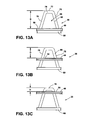
- FIGS. 14A - 14C illustrate the cross-sectional area of the opening 328 defined by the cutting edge 336 of each tooth 312 changes by a proportional amount between cutting positions.
- the side sections 330, 332 of the cutting edge 336 are substantially curved, the cutting size varies nonlinearly from the minimum cutting thickness to the maximum cutting thickness.
- the cross sectional area of the opening 328 may be defined by side sections 330, 332 of cutting edges 336 and the carrier disk 40 that are variably curved in both convex and concave form (not shown) indicating that processed food having a desirable non-uniform cross section will be produced by the food processor 10.
- processed food with non-uniform cross section can be appreciated for both the unique appearance the processed food provides to users and for the increased cross sectional surface area of the processed food that may aid users in subsequent steps in food preparation, as in the examples of desirably melting or cooking the processed food.
- the thickness adjustment assembly in the illustrative embodiment moves the carrier disk relative to the cutting teeth, in other embodiments the assembly may move the cutting teeth relative to the carrier disk.
- the cutting tool 16 is illustrated herein as an adjustable cutting disk assembly, it should be appreciated that in other embodiments the cutting tool may be an adjustable ice shaver or other adjustable cutting device.
- the food processor 10 is herein illustrated as a conventional domestic food processor, the features and aspects disclosed herein can also be implemented in other types of food processing devices such as automatic food slicers, dicers, ice shavers and the like.
- the adjustable cutting disk assembly may include a thickness adjustment assembly that is integrated with the disk assembly. In such embodiments, the thickness adjustment assembly may include an externally-operated user control device or control device that requires the adjustable cutting disk assembly to be removed from the bowl for adjustment.
Description
- The present disclosure relates generally to a domestic food processing device, and, more particularly, to an adjustable cutting assembly for a food processing device.
- A food processing device is a motorized domestic appliance for manipulating (e.g., chopping, slicing, dicing, shredding, grating, or blending) food items. Such an appliance includes a bowl with a removable lid. Food items are inserted into the bowl through a feed tube formed in the lid where they are cut by motor-driven cutting tool and collect in the bottom of the bowl. Some food processors also include an outlet on the bowl that guides the processed pieces of food into an outside bin, container, or other bowl.
- Food processors typically come equipped with a number of interchangeable cutting tools for slicing, shredding, or other food processing operations. One common cutting tool is a rotating disk-type cutter. Such a cutting tool may include a rotating disk having a cutting blade fixed thereto. The cutting blade is secured to the rotating disk at a location adjacent to an aperture formed in the disk so that food items cut by the blade fall through the aperture. Another rotating disk-type cutting tool may include a rotating disk with a plurality of cutting teeth formed thereon for shredding food items. Each cutting tooth is positioned over an aperture formed in the disk so that food items cut by the tooth fall through the aperture.
-
EP-A1-2382902 discloses a food processor with an adjustable cutting assembly on which the precharacterizing portion ofclaim 1 is based. Juicing or grinding disks carrying a plurality of teeth are illustrated inUS-A-2003/0094522 andGB-A-2430141 - The present invention provides a cutting assembly for a food processing device as defined by
claim 1. - The cutting edge of each cutting tooth may include a first section extending downwardly from the tip to define a first side of the opening and a second section extending downwardly from the tip to define a second side of the opening. The opening of each cutting tooth may be a trapezoidal-shaped opening, a rectangular-shaped opening, but is not limited to a specific shape. The shape may have straight or curved surfaces that are predetermined by the desired shape of the cut food.
- The cutting assembly may include a support disk positioned substantially parallel to and at least one of above and below the planar disk. The support disk may have the plurality of cutting teeth extending upwardly therefrom. In some embodiments, each cutting tooth may have an inner wall that extends inwardly from the opening to define a channel extending downwardly through the support disk. Additionally, the cutting teeth may be arranged in a number of staggered or offset rows. Each staggered or offset row of the cutting teeth may be positioned along a radial line extending outwardly from the center of the support disk.
- The support disk may be removably coupled to the planar disk. Additionally, the cutting assembly may further include a hub secured to the planar disk. The hub may have a base and a platform formed at an upper end of the base. The support disk may be positioned between the platform of the hub and the planar disk.
- Further, each slot may have at least one of, but is not limited to an oval shaped, a circular shaped, a rectangular shaped or an oblong-shaped opening in the upper surface of the planar disk.
- Another aspect of the invention provides a food processing device including such a cutting assembly. The food processing device includes a base having a motor positioned therein, a removable bowl coupled to the base, and a removable lid coupled to the bowl so as to define a processing chamber. The lid includes a feed tube that opens into the bowl. The cutting assembly is positioned in the processing chamber and driven by the motor to cut food items advanced through the feed tube. Additionally, the food processing device includes an adjustment assembly having a lever extending outwardly from the base. The lever is operable to move the planar disk relative to the cutting teeth while the cutting assembly is driven by the motor.
- In some embodiments, the cutting assembly may also include a support disk positioned below the planar disk. The support disk may have the plurality of cutting teeth extending upwardly therefrom.
- The food processing device may further include a drive stem coupled to an output shaft of the motor and the support disk. The food processing device may further include an adaptor removably coupled to the planar disk. The adjustment assembly may further include a screw-type drive assembly coupled to the adaptor and the lever. Movement of the lever in a first direction may cause the screw-type drive assembly to move the planar disk downward relative to the cutting teeth, and movement of the lever in a second direction may cause the screw-type drive assembly to move the planar disk upward relative to the cutting teeth.
- The lever may be operable to move the support disk while the cutting assembly is driven by the motor.
- The processing chamber may have an upper compartment and a lower compartment, and each cutting tooth has an inner wall that extends inwardly from the opening to define a channel extending downwardly through the support disk to advance food items cut by the cutting tooth from the upper compartment to the lower compartment.
- The opening of each cutting tooth may be at least one of an arcuate-shaped and trapezoidal-shaped opening. However, it is contemplated that other geometrical shapes or a combination of shapes such as a cutting tooth having a trapezoidal-shaped opening with arcuate sidewalls is also discussed.
- The invention will be exemplified with reference to the accompanying drawings, in which:
-
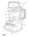
FIG. 1 is a perspective view of a food processing device; -
FIG. 2 is an exploded perspective view of one embodiment of an adjustable cutting tool of the food processing device ofFIG. 1 ; -
FIG. 3 is a partial exploded perspective view of an alternative adjustable cutting tool of the food processing device ofFIG. 1 ; -
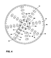
FIG. 4 is a top plan view of an adjustable cutting tool ofFIG. 2 ; -
FIG. 5 is a perspective view of an alternative lower plate for the adjustable cutting tool ofFIG. 1 ; -
FIG. 6 is a top plan view of the lower plate ofFIG. 5 ; -
FIG. 7 is a side elevation view of the lower plate ofFIG. 5 ; -
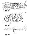
FIG. 8a is a perspective view of another embodiment of a lower plate for the adjustable cutting tool ofFIG. 1 ; -
FIG. 8b is a cross-sectional side elevation view of the lower plate ofFIG. 8a ; -
FIG. 9 is an exploded perspective view of an alternative adjustable cutting tool assembly; -
FIG. 10 is an exploded, partial cross-sectional perspective view of the food processor ofFIG. 1 ; -
FIG. 11 is a partial cross-sectional view of the food processing device ofFIG. 1 showing the adjustable cutting tool ofFIG. 2 in one cutting position; -
FIG. 12 is a view similar toFIG. 11 showing the adjustable cutting tool ofFIG. 2 in another cutting position; -
FIG. 13A is a cross-sectional elevation view of a cutting tooth and a planar disk of the adjustable cutting tool positioned in one cutting position; -
FIG. 13B illustrates the cutting tooth ofFIG. 13A and the planar disk of the adjustable cutting tool positioned in another cutting position; -
FIG. 13C illustrates the cutting tooth ofFIG. 13A and the planar disk of the adjustable cutting tool positioned in another cutting position; -
FIG. 14A is a cross-sectional elevation view of an alternative cutting tooth and a planar disk of the adjustable cutting tool positioned in one cutting position; -
FIG. 14B illustrates the alternative cutting tooth ofFIG. 14A and the planar disk of the adjustable cutting tool positioned in another cutting position; and -
FIG. 14c illustrates the alternative cutting tooth ofFIG. 14A and the planar disk of the adjustable cutting tool positioned in another cutting position. - While the concepts of the present disclosure are susceptible to various modifications and alternative forms, specific exemplary embodiments thereof have been shown by way of example in the drawings and will herein be described in detail. It should be understood, however, that there is no intent to limit the concepts of the present disclosure to the particular forms disclosed, but on the contrary, the intention is to cover all modifications, equivalents, and alternatives falling within the spirit and scope of the disclosure.
- Referring now to
FIG. 1 , a food processing device orfood processor 10 is shown. Thefood processor 10 has a base 12 that houses amotor 14 and acontrol unit 15. Under the control of thecontrol unit 15, themotor 14 drives anadjustable cutting tool 16 to cut food items such as cheeses, meats, fruits, and vegetables. The base 12 also includes one or more buttons, switches, dials, or other types ofcontrols 18 in communication with thecontrol unit 15. A user operates thecontrols 18 to control the operation of themotor 14 and hence thefood processor 10. For example, one of thecontrols 18 may be operable to turn themotor 14 on and off while anothercontrol 18 may change the motor's speed. - As will be understood by those skilled in the art, the
control unit 15 may comprise at least one of analog and/or digital circuitry to process electrical signals received from the motor 14 (or other components of the food processor 10) and provide electrical control signals to the motor or other components of thefood processor 10. For example, thecontrol unit 15 may be embodied as a microcontroller that executes firmware routines to control the operation of thefood processor 10. - A removable receptacle or
bowl 20 is secured to thebase 12. The bowl's handle facilitates placement of thebowl 20 on thebase 12. Thebowl 20 includes aremovable lid 22 secured to its upper peripheral edge. Thelid 22 has afeed tube 24 formed thereon through which food items such as, for example, fruits, vegetables, and so forth are inserted into thebowl 20 to be processed by thefood processor 10. Collectively, thelid 22 and thebowl 20 define aprocessing chamber 26 where food items are processed by the cuttingtool 16. - The
bowl 20, thelid 22, and thefeed tube 24 are generally made of, but are not limited to a transparent or translucent plastic material so that the contents of thefood processor 10 can be viewed by a user without removing thelid 22 from thebowl 20. Moreover, one or more locking mechanisms may be used to lock the bowl to thebase 12 and thelid 22 to thebowl 20. - Referring now to
FIGS. 2 - 7 , theadjustable cutting tool 16 is illustrated as an adjustablecutting disk assembly 30 includes cutters that may be used to make shredding or grating cuts. Alternatively, thedisk assembly 30 may include cutters for making julienne, french fry, ice, or other style cuts. Theassembly 30 may include anupper plate 32, alower plate 34 including a plurality of cuttingteeth 36, and acentral hub 38. Theupper plate 32 may include acarrier disk 40 having substantially planar body 42 extending radially outward from acentral bore 44 defined in thecarrier disk 40 to a circularouter perimeter 46. Thecarrier disk 40 may also have arim 48 that extends vertically from theouter perimeter 46 of the body 42. Thecarrier disk 40 may have a diameter that is slightly less than the inner diameter of thebowl 20. As such, therim 48 is positioned adjacent to, but is spaced slightly apart from, the inner wall of thebowl 20 to permit the rotation of theassembly 30 within thebowl 20, as shown inFIGS. 11 and12 . It should be appreciated that therim 48 may be omitted. - A plurality of
slots 50 are defined in thecarrier disk 40, and the cuttingteeth 36 of thelower plate 34 are positioned in theslots 50. As described in greater detail below, theslots 50 and the cuttingteeth 36 of thedisk 40 collectively define aregion 52 of the carrier disk 40 (seeFIG. 4 ) in which food items may be cut by the cuttingtool 16. - As illustrated, the
slots 50 are arranged in a number ofstaggered rows 54 that extend radially outward from thecentral bore 44. The slots may be arranged in a number of configurations of curved rows that sweep forward or backward. The slots may be dispersed asymmetrically over the planar disk. As shown inFIGS. 2 - 7 , eachslot 50 has an oblong-shapedopening 56 defined in anupper surface 58 of thecarrier disk 40. As described in greater detail below, theopenings 56 are sized to receive the cuttingteeth 36 of thelower plate 34. It should be appreciated that each opening may be rectangular, oval, or other geometric-shape sized to receive one of the cuttingteeth 36 of thelower plate 34 and is not limited to a specific size or shape. - As shown in
FIGS. 2 and3 , thelower plate 34 of theassembly 30 is positioned below theupper plate 32. Thelower plate 34 includes asupport disk 60 having a substantiallyplanar body 62 that extends radially outward from acentral bore 64 defined in thedisk 60 to a circularouter perimeter 66. Thesupport disk 60 also has arim 68 that extends vertically from theouter perimeter 66 of thebody 62. Thesupport disk 60 has a diameter that is slightly less than the inner diameter of thebowl 20. As such, therim 68, like therim 48 of thecarrier disk 40, is positioned adjacent to, but is spaced slightly apart from, the inner wall of thebowl 20 to permit the rotation of theassembly 30 within thebowl 20. It should be appreciated that therim 68 may be omitted. - The
lower plate 34 also includes the plurality of cuttingteeth 36, which extend upwardly from thesupport disk 60. As illustrated, thesupport disk 60 is embodied as a monolithic structure formed from a metallic material, such as, but not limited to, steel, and the cuttingteeth 36 are formed by a metal stamping operation. However, it should be appreciated that the components of the support disk 60 (e.g., theteeth 36, thebody 62, the rim 68) may be embodied as separate components secured to one another by an adhesive or other suitable fastener. For example, one ormore cutting teeth 36 may be included on a frame that is removably coupled to the support disk. As shown inFIGS. 8A and 8B , theplanar body 62 of thelower plate 34 may be modified or replaced with, for example, asupport frame 67 having a plurality ofarms 69 connected to therim 68. The cuttingteeth 36 are arranged along eacharm 69 and extend upwardly therefrom. - As shown in
FIG. 2 , the cuttingteeth 36 correspond to theslots 50 defined in theupper plate 32 such that onetooth 36 is positioned in eachslot 50. Each cuttingtooth 36 of thelower plate 34 includes a shell 70 and acutting edge 72 that is formed on aside 74 of the shell 70. Thecutting edge 72 has atop edge 76, which is positioned above theupper surface 58 of theupper plate 32, and a pair ofside sections top edge 76 to abase 82 of the cuttingtooth 36. As illustrated inFIGS. 2 - 4 , theside sections base 82 of eachtooth 36 is attached to theplanar body 62 of thedisk 60 and partially encloses aslot 84 extending through theplanar body 62. - The
cutting edge 72 of eachtooth 36 defines anopening 86 in theside 74 of the shell 70. As illustrated, theopening 86 is a trapezoidal-shaped opening. Alternatively, the opening may be curved or bowed, rectangular, triangular, or other geometric shape. Aninner wall 88 extends inwardly from theopening 86 to define achannel 90 in each shell 70. Thechannel 90 extends downwardly throughslot 84 defined in theplanar body 62 such that food items cut by thetooth 36 are advanced downward, as described in greater detail below. Thechannel 90 is inclined or sloped such that food is guided from theupper surface 58 of thecarrier disk 40, through thesupport disk 60, and out theslot 84. The magnitude of the angle or slope of thechannel 90 is selected such that the cut food items are guided smoothly out of theslot 84. - As shown in
FIG. 2 , the cuttingteeth 36 are arranged in a number ofstaggered rows 92 that correspond to thestaggered rows 54 defined in theupper plate 32. Eachstaggered row 92 may positioned along aradial line 94 extending outwardly from thecenter 96 of thebody 62 of thesupport disk 60. Alternatively, eachstaggered row 92 may be offset from the staggered line in varying patterns and angles as illustrated inFIGS. 3 and4 . Within eachrow 92, agap 98 is defined between thetop edges 76 ofadjacent teeth 36. As illustrated, the magnitude of eachgap 98 is substantially equal such that theteeth 36 in eachrow 92 are at least one of equally and variably spaced apart in a predefined pattern. Alternatively, the teeth may be arranged in a number of curved rows that sweep forward or backward. Additionally, the teeth may be dispersed asymmetrically over the support disk. The gaps defined between thetop edges 76 of adjacent cuttingteeth 36 may be different or asymmetrical so that no gap is equal to any other gap. - Referring specifically to
FIGS. 3 and5 - 7 , an alternative lower plate (hereinafter lower plate 310) including an alternative set of cuttingteeth 312 is illustrated. Thelower plate 310 may be used in place of thelower plate 34 described above in reference toFIGS. 2 and4 . Thelower plate 310, like thelower plate 34, includes asupport disk 314 having a substantiallyplanar body 62 that extends radially outward from acentral bore 64 defined in thedisk 314 to a circularouter perimeter 66. Thesupport disk 314 also has arim 68 that extends vertically from theouter perimeter 66 of thebody 62. Thesupport disk 314 has a diameter that is slightly less than the inner diameter of thebowl 20. As such, therim 68, like therim 48 of thecarrier disk 40, is positioned adjacent to, but is spaced slightly apart from, the inner wall of thebowl 20 to permit the rotation of theassembly 30 within thebowl 20. It should be appreciated that in other embodiments therim 68 may be omitted. - As shown in
FIGS. 3 and5 , the plurality of cuttingteeth 312 extend upwardly from thesupport disk 314. The cuttingteeth 312 correspond to theslots 50 defined in theupper plate 32 such that onetooth 312 is positioned in eachslot 50. Each cuttingtooth 312 of thelower plate 310 includes ashell 320 and acutting edge 322 that is formed on aside 324 of theshell 320. Each cuttingtooth 312 has a base 326 that is attached theplanar body 62 of thedisk 314 and partially encloses aslot 328 extending through theplanar body 62. Thecutting edge 322 has a pair of slopedside sections forward end 334 of theslot 328 to atip 336 of thecutting edge 322. Thetip 336 is positioned above theupper surface 58 of thecarrier disk 40. - The
cutting edge 322 of eachtooth 312 defines anopening 338 in theside 324 of theshell 320, as shown inFIG. 7 . In the illustrative embodiment, theopening 338 is a trapezoidal-shaped opening. In other embodiments, the opening may be curved or bowed, rectangular, triangular, or other geometric shape. Aninner wall 340 extends inwardly from theopening 338 to define achannel 342 in eachshell 320. Thechannel 342 extends downwardly through theslot 328 defined in theplanar body 62 such that food items cut by thetooth 312 are advanced downward, as described in greater detail below. Arear surface 344 of theinner wall 340 is inclined or sloped such that food is guided from theupper surface 58 of thecarrier disk 40, through thesupport disk 60, and out theslot 328. The magnitude of the angle or slope of therear surface 344 defining thechannel 90 is selected such that the cut food items are guided smoothly out of theslot 328. - As shown in
FIG. 6 , the cuttingteeth 312 are arranged in a number ofstaggered rows 350 that correspond to thestaggered rows 54 defined in theupper plate 32. Eachstaggered row 350 is positioned along aradial line 94 extending outwardly from thecenter 96 of thebody 62 of thesupport disk 314. Within eachrow 350, agap 98 is defined between thetips 336 ofadjacent teeth 312. In the illustrative embodiment, the magnitude of eachgap 98 is substantially equal such that theteeth 36 in eachrow 92 are equally spaced apart. In other embodiments, the teeth may be arranged in a number of curved rows that sweep forward or backward. In still other embodiments, the teeth may be dispersed asymmetrically over the support disk. In other embodiments, the gaps defined between the tips of adjacent cutting teeth may be different or asymmetrical so that no gap is equal to any other gap. - Returning to
FIG. 2 , theupper plate 32 and thelower plate 34 are coupled together via acentral hub 38 of theassembly 30. Thecentral hub 38 may include acollar 112 and acentral plate 114 that are secured to theupper plate 32. Thecollar 112 includes aplatform 116 positioned below theplates cylindrical body 118 that extends downwardly of theplatform 116. Thecylindrical body 118 has a pair ofslots 120 defined therein. Eachslot 120 includes avertical section 122 that extends upwardly from alower end 124 of thebody 118 and ahorizontal section 126 that is connected to thevertical section 122. - The
platform 116 has anupper surface 130, and the collar 112 a plurality ofposts 132 that extend upwardly from theupper surface 130. Eachpost 132 is arranged circumferentially around acentral bore 134 defined in theupper surface 130. As illustrated, eachpost 132 has a cylindricalouter surface 136 and a circulartop surface 138. It should be appreciated that each post may have a number of substantially planar outer surfaces. Alternatively, the number of posts may be greater or fewer. - The
posts 132 extend throughopenings 139 defined in thelower plate 34 and throughholes 166 inframe 162 toupper ends 140, as described in detail below. At theupper end 140, eachpost 132 is secured to thecentral plate 114 of thehub 38, thereby joining thecollar 112 with thecentral plate 114. As shown inFIG. 2 , thecentral plate 114 is positioned above theupper surface 58 of theupper plate 32. Thecentral plate 114 includes acylindrical body 142 and alower flange 144 that extends outwardly from thebody 142. It should be appreciated that the central plate may also include an ergonomic grip that a user may grasp to carry thecutting disk assembly 30. - The
central plate 114 has acentral bore 146 that extends downwardly from theupper surface 148 of thebody 142, which is axially aligned with thebore 134 of the platform, thecentral bore 64 of thesupport disk 60, and thecentral bore 44 of thecarrier disk 40. In that way, thebores assembly 30. Theflange 144 includes a plurality ofears 152 that correspond to theposts 132 of thecollar 112, and eachear 152 is secured to acorresponding post 132 via afastener 154. - As illustrated, the
fasteners 154 are screws that pass throughholes 156 defined in theears 152 and are threaded intoapertures 158 defined in thetop surfaces 138 of theposts 132. As shown inFIG. 2 , eachfastener 154 also passes through ahole 160 defined in thecarrier disk 40 of theupper plate 32 such that thecarrier disk 40 is clamped between theposts 132 of thecollar 112 and thecentral plate 114. - The
central hub 38 of theassembly 30 may also include aframe 162 having asupport plate 164 positioned between thedisk 60 of thelower plate 34 and theplatform 116 of thecollar 112. Theframe 162 and thecollar 112 of thecentral hub 38 may be configured to slide relative to one another. In the illustrative embodiment, theplate 164 has a plurality ofcylindrical bores 166 defined therein, which are sized to receive theposts 132 of thecollar 112. As such, theposts 132 may slide along thebores 166 when theframe 162 is moved upwardly and downwardly relative to thecollar 112 or thecollar 112 is moved upwardly and downwardly relative to theframe 162. - The
support plate 164 may be secured to thelower plate 34 via a number offasteners 168. As illustrated, thefasteners 168 are screws that pass through holes 170 defined in thesupport disk 60 of thelower plate 34 and are threaded intoapertures 172 defined in theupper surface 174 of thesupport plate 164. Because a user may remove thefasteners 154, 168 (i.e., the screws) securing theupper plate 32 and thelower plate 34 to thecentral hub 38, theupper plate 32 is removable coupled to thelower plate 34. Alternatively, one or both sets of fasteners may be omitted and the upper plate may be removably coupled to the lower plate through known fastening mechanisms. - For example, as shown in
FIG. 9 , theupper plate 32 may include acarrier disk 176 that is positioned above thelower flange 144 of thecentral plate 114. Theassembly 30 may also include an internally-threadedknob 178 that engages a plurality ofexternal threads 180 formed on thecylindrical body 142. Thecarrier disk 176 may have acentral opening 182 sized to receive thecylindrical body 142 such that thecarrier disk 176 may slide along thebody 142 to engage theupper surface 184 of thelower flange 144 of thecentral plate 114. Thecarrier disk 176 may then be clamped between theupper surface 184 of thelower flange 144 and theknob 178. - The
cutting disk assembly 30 may include a detent secured to thecarrier disk 176 that may be configured to engage one or more teeth defined in the central hub. Theupper plate 32 and thelower plate 34 may be fixed together such that theplates - Returning to
FIG. 2 , theframe 162 of thecentral hub 38 may have an uppercentral shaft 186 that extends upwardly from thesupport plate 164 and a lowercentral shaft 188 that extends downwardly from thesupport plate 164. Apassageway 190 may extend through theshafts support plate 164. Thelower shaft 188 may have asocket 192 defined therein keyed to match theupper end 194 of a drive stem 196 (seeFIG. 10 ). As illustrated, theupper end 194 of thestem 196 includes two flat surfaces (not shown) connected at each end by a curved surface (not shown), and thesocket 192 has a corresponding geometric shape that is sized to receive theupper end 194 of thestem 196. When thecutting disk assembly 30 is seated on thedrive stem 196, as shown inFIG. 11 , the keyedupper end 194 of thestem 196 is received in thesocket 192 of thecentral shaft 188. - It should be appreciated that the arrangement of the
socket 192 andkeyed end 194 may be reversed, with thekeyed end 194 being formed on thecentral shaft 188 and the socket being defined in thedrive stem 196. It should also be appreciated that other methods of attachment may be used to secure the drive stem to the cutting assembly. For example, a pair of tabs (not illustrated) may extend from the upper end of thedrive stem 196, and those tabs may be received in a corresponding socket defined in thecentral shaft 188. - As described above, the
collar 112 of thecentral hub 38 may be movable relative to theframe 162 of thecentral hub 38. Because theupper plate 32 is secured to thecollar 112 and thelower plate 34 is secured to theframe 162, movement of thecollar 112 or theframe 162 causes movement of theplates teeth 36 relative to thecarrier disk 40. As shown inFIG. 11 , a vertical distance, D, is defined between thetop edge 76 of thecutting edge 72 of each cuttingtooth 36 and theupper surface 58 of thecarrier disk 40. The distance D defines a cutting thickness of food items processed by thecutting disk assembly 30. In other words, the thickness of the pieces of food items cut by thefood processor 10 is determined by the distance D between thetop edge 76 of thecutting edge 72 of each cuttingtooth 36 and theupper surface 58 of thecarrier disk 40. As the distance D between thetop edges 76 of the cutting edges 72 of the cuttingteeth 36 and theupper surface 58 of thecarrier disk 40 increases, thicker pieces of food items are created; while thinner pieces of food items are created when the distance D between thetop edges 76 of the cutting edges 72 and theupper surface 58 of thecarrier disk 40 decreases. As described in greater detail below, thefood processor 10 includes athickness adjustment assembly 198 that may be operable by a user to adjust the distance D to vary the cutting thickness of thefood processor 10 while thecutting disk assembly 30 is driven by themotor 14. - Referring now to
FIG. 10 , thefood processor 10 includes themotor 14 that is configured to rotate thecutting disk assembly 30. Themotor 14 includes anoutput shaft 200 extending upwardly from thebase 12. Theoutput shaft 200 is coupled to thedrive stem 196, which is in turn coupled to thecutting disk assembly 30 as described above. As such, rotation of theoutput shaft 200 causes rotation of thecutting disk assembly 30. - The
thickness adjustment assembly 198 of thefood processor 10 is operable by a user to vary the cutting thickness of thefood processor 10 while thecutting disk assembly 30 is driven by themotor 14, thereby creating thicker or thinner pieces of cut food items during a cutting operation. Theadjustment assembly 198 may include a user-operatedcontrol device 202 that is located outside of theprocessing chamber 26 defined by thebowl 20 and thelid 22. What is meant herein by the term "outside" as it relates to the location of the user-operated control device relative to the bowl or the processing chamber is that the structure of the control device contacted by the user to operate the device is positioned external to the bowl and lid so that it may be operated by the user while the lid is secured to the bowl, thereby allowing the cutting thickness of the food processor to be adjusted while thecutting disk assembly 30 is driven by themotor 14. - For example, as illustrated and described herein, the
external control device 202 is embodied as acontrol lever 204 that extends outwardly from thebase 12 and is moveable relative to the base 12 to change the cutting thickness of thecutting disk assembly 30 without removing thelid 22 from thebowl 20. In such a configuration, the user moves thecontrol lever 204 one direction or the other to change (i.e., increase or decrease) the distance D between thetop edges 76 of the cuttingteeth 36 and theupper surface 58 of thecarrier disk 40. In the illustrative embodiment, the thickness adjustment assembly is manually operated by the user-operated control device, but it should be appreciated that in other embodiments the adjustment assembly may be electrically-operated, including, for example, a motor, an electronic controller, and sensors such that the thickness adjustment assembly may be operated automatically. It should also be appreciated that other user-operated control devices, such as knobs, dials, buttons, servo-motors, or the like, may be substituted for thecontrol lever 204. - The
adjustment assembly 198 may include a two-piece adaptor 210 coupled to thecollar 112 of thecentral hub 38 of thecutting disk assembly 30, alift device 212 supporting theadaptor 210, and agear assembly 214 positioned in thebase 12. Merely by way of example, the adjustment assembly is shown and described in PCT International Patent Application No.PCT/CN2011/000311, which was filed on February 25, 2011 PCT/CN2011/001487, which was filed on September 1, 2011 - As shown in
FIG. 10 , theadaptor 210 includes anupper shaft 220 secured to thecollar 112 of thecutting disk assembly 30 and alower shaft 222 rotatively coupled to thelift device 212. Theupper shaft 220 has acylindrical body 224 that extends from anupper end 226 to alower end 228. Theshaft 220 of theadaptor 210 also has apassageway 230 that extends through thebody 224. When assembled, theshaft 220 is positioned over thedrive stem 196 and the lower end of thecentral shaft 188 of thecutting disk assembly 30 such that thestem 196 andshaft 188 are received in thepassageway 230. - The
upper end 226 of theupper shaft 220 has a pair oftabs 232 extending outwardly therefrom. Eachtab 232 is positioned in acorresponding slot 120 defined in thecollar 112, thereby securing theupper shaft 220 ofadaptor 210 to thecutting disk assembly 30 such that rotation of thecutting disk assembly 30 causes rotation of theupper shaft 220. As shown inFIG. 10 - 11 , thelower shaft 222 of theadaptor 210 is torsionally secured to thelower end 228 of theshaft 220 such that the rotation of theupper shaft 220 causes rotation of thelower shaft 222. As illustrated, a plurality ofteeth 234 are formed at thelower end 228 of theshaft 220, and a corresponding plurality ofteeth 236 are formed at anupper end 238 of thelower shaft 222. When theadaptor 210 is assembled, theteeth 236 of thelower shaft 222 are interdigitated with theteeth 234 of theupper shaft 220, thereby securing theshafts shaft 220 to theshaft 222. - As shown in
FIG. 11 , theadaptor 210 includes abiasing mechanism 240 configured to bias theupper shaft 220 into engagement with thelower shaft 222. Thebiasing mechanism 240 includes asleeve 242 that is positioned in thepassageway 230 and a biasing element, such as aspring 244. Thesleeve 242 has thedrive stem 196 of thefood processor 10 extending therethrough. - The
sleeve 242 contacts thecentral shaft 188 of thecutting disk assembly 30. Thesleeve 242 has aflange 248 that extends outwardly from its upper end. Similarly, theupper shaft 220 includes aninner flange 250 extending inwardly into thepassageway 230. Thespring 244 is positioned between theflanges shaft 220 downward to maintain engagement between theteeth shafts sleeve 242 also includes alip 252 configured to engage theflange 250 when theupper shaft 220 not assembled with thecutting disk assembly 30. - As described above, the
thickness adjustment assembly 198 also includes alift device 212 operable to move the adaptor 210 (and hence carrier disk 40) upwardly and downwardly relative to thebase 12 of the food processor. As shown inFIG. 11 , thelift device 212 includes a screw-type drive assembly having an internally-threadedupper sleeve 260 engaged with an externally-threadedlower sleeve 262. Thelower sleeve 262 is secured to the base 12 such that thesleeve 262 does not rotate. In use counter-clockwise rotation of theupper sleeve 260 may cause downward movement of theupper sleeve 260, while clockwise rotation of theupper sleeve 260 may cause upward movement of theupper sleeve 260. - The
lower shaft 222 of theadaptor 210 is rotatively coupled to theupper sleeve 260 of thelift device 212 via abearing 264. In that way, the shaft 222 (and hence cutting disk assembly 30) is permitted to rotate relative to thelift device 212. At the same time, the bearing 264 fixes the axial position of theshaft 222 relative to theupper sleeve 260 such that upward and downward movement of theupper sleeve 260 causes upward and downward movement of theshaft 222. - As described above and shown in
FIG. 10 , thethickness adjustment assembly 198 also includes agear assembly 214, which is positioned in thebase 12 of thefood processor 10. Thegear assembly 214 includes adrive gear 270 and aguide gear 272 that are pivotally coupled to thebase 12. Each of thegears teeth drive gear 270 causes rotation of theguide gear 272. - The
upper sleeve 260 of thelift device 212 is movably coupled to theguide gear 272. As shown inFIG. 10 , theupper sleeve 260 has a plurality ofgrooves 280 defined therein, and theguide gear 272 has a corresponding plurality ofsplines 282 that are received in thegrooves 280. Thesplines 282 and thegrooves 280 cooperate to couple thesleeve 260 to theguide gear 272 while permitting thesleeve 260 to translate upwardly and downwardly relative to thegear 272. As such, rotation of theguide gear 272 by thedrive gear 270 causes rotation of theupper sleeve 260 relative to thelower sleeve 262, thereby causing movement of theupper sleeve 260 upwardly or downwardly relative to thebase 12. - As described above, the
thickness adjustment assembly 198 includes acontrol lever 204 that extends outwardly from thebase 12 of thefood processor 10. As illustrated, thecontrol lever 204 has agrip 284 spaced apart from thebase 12 and anarm 286 that extends from thegrip 284 into the base 12 through aslot 288. Thearm 286 is coupled to thedrive gear 270 within thebase 12 such that movement of thecontrol lever 204 along theslot 288 causes rotation of thedrive gear 270, thereby operating thethickness adjustment assembly 198 to change the cutting thickness of thecutting disk assembly 30. - Referring now to
FIGS. 11 and12 , theremovable lid 22 is configured to be secured to arim 290 of thebowl 20. Thelid 22 of thefood processor 10 has aninner surface 292 and asleeve 294 that extends downwardly from theinner surface 292 thereof. Thesleeve 294 has anaperture 296 defined in alower end 298 thereof, which is sized to receive atip 300 of thedrive stem 196. - In use, the user may attach the
lid 22 to theupper rim 290 of thebowl 20. To do so, the user aligns thesleeve 294 of thelid 22 with thetip 300 of thedrive stem 196. The user then advances thelid 22 downward such that thelower end 298 of thesleeve 294 engages theupper end 302 of theframe 162 of thecentral hub 38. As the user continues to advance thelid 22 downward, the bias exerted by thespring 244 of theadaptor 210 is overcome, and the cuttingteeth 36 are moved downward such that the distance D defined between thetop edges 76 of the cutting edges 72 of theteeth 36 and theupper surface 58 of thecarrier disk 40 is decreased. As shown inFIG. 11 , when thelid 22 contacts theupper rim 290 of thebowl 20, the distance D defined between thetop edges 76 of the cutting edges 72 of theteeth 36 and theupper surface 58 of thecarrier disk 40 is relatively minimal, corresponding to the minimal cutting thickness of thecutting disk assembly 30. - In use, a user operates the
controls 18 to energize themotor 14 to rotate theoutput shaft 200 and thedrive stem 196 attached thereto. Because thecutting disk assembly 30 is secured to thedrive stem 196, rotation of theoutput shaft 200 causes rotation of thecutting disk assembly 30. While themotor 14 is energized, the user may advance food items into theprocessing chamber 26 through thefeed tube 24 to be cut by thecutting disk assembly 30. - If the user desires to change the cutting thickness during the cutting operation, the user may grasp the
grip 284 and advance thecontrol lever 204 along theslot 288. Movement of thecontrol lever 204 causes thecontrol lever 204 to operate thegear assembly 214 to rotate theguide gear 272. As described above, rotation of theguide gear 272 causes rotation of theupper sleeve 260 relative to thelower sleeve 262 and moves theupper sleeve 260 downwardly relative to thebase 12. Because theadaptor 210 is secured to both theupper sleeve 260 and thecarrier disk 40 of theupper plate 32, movement of theupper sleeve 260 causes movement of thedisk 40 relative to the cuttingteeth 36, thereby increasing the distance D defined between thetop edges 76 of the cutting edges 72 of the cuttingteeth 36 and theupper surface 58 of thecarrier disk 40. As shown inFIG. 12 , the distance D is relatively larger than the distance D shown inFIG. 11 , indicating that thicker food items will be produced by thefood processor 10. - As described above, the cutting
teeth 36 cooperate to define aregion 52 of thecarrier disk 40 in which food items may be cut by the cuttingtool 16. The cuttingteeth 36 are arranged over thecarrier disk 40 such that a consistent amount is removed from a food item with each rotation of thecutting disk assembly 30 in each of the cutting positions. In other words, the cuttingteeth 36 are arranged such that the cutting edges 72 of theteeth 36 overlap when the distance D defined between thetop edges 76 of the cutting edges 72 of theteeth 36 and theupper surface 58 of thecarrier disk 40 is relatively minimal or at a maximum. In that way, the entire surface of a food item advanced into theprocessing chamber 26 is cut by theteeth 36. - Further, as shown in
FIGS. 13A - 13C , the cross-sectional area of theopening 86 defined by thecutting edge 72 of eachtooth 36 changes by a proportional amount between cutting positions. Further, because theside sections cutting edge 72 are substantially straight, the cutting size varies linearly from the minimum cutting thickness to the maximum cutting thickness. - Alternatively,
FIGS. 14A - 14C illustrate the cross-sectional area of theopening 328 defined by thecutting edge 336 of eachtooth 312 changes by a proportional amount between cutting positions. Further, because theside sections cutting edge 336 are substantially curved, the cutting size varies nonlinearly from the minimum cutting thickness to the maximum cutting thickness. Additionally, it is understood that the cross sectional area of theopening 328 may be defined byside sections edges 336 and thecarrier disk 40 that are variably curved in both convex and concave form (not shown) indicating that processed food having a desirable non-uniform cross section will be produced by thefood processor 10. The desirability of processed food with non-uniform cross section can be appreciated for both the unique appearance the processed food provides to users and for the increased cross sectional surface area of the processed food that may aid users in subsequent steps in food preparation, as in the examples of desirably melting or cooking the processed food. - While the disclosure has been illustrated and described in detail in the drawings and foregoing description, such an illustration and description is to be considered as exemplary and not restrictive in character, it being understood that only illustrative embodiments have been shown and described and that all changes and modifications that come within the spirit of the disclosure are desired to be protected.
- For example, while the thickness adjustment assembly in the illustrative embodiment moves the carrier disk relative to the cutting teeth, in other embodiments the assembly may move the cutting teeth relative to the carrier disk. Additionally, while the
cutting tool 16 is illustrated herein as an adjustable cutting disk assembly, it should be appreciated that in other embodiments the cutting tool may be an adjustable ice shaver or other adjustable cutting device. Further, while thefood processor 10 is herein illustrated as a conventional domestic food processor, the features and aspects disclosed herein can also be implemented in other types of food processing devices such as automatic food slicers, dicers, ice shavers and the like. Further, in other embodiments, the adjustable cutting disk assembly may include a thickness adjustment assembly that is integrated with the disk assembly. In such embodiments, the thickness adjustment assembly may include an externally-operated user control device or control device that requires the adjustable cutting disk assembly to be removed from the bowl for adjustment. - There are a plurality of advantages of the present disclosure arising from the various features of the method, apparatus, and system described herein. It will be noted that alternative embodiments of the method, apparatus, and system of the present disclosure may not include all of the features described yet still benefit from at least some of the advantages of such features. Those of ordinary skill in the art may readily devise their own implementations of the method, apparatus, and system that incorporate one or more of the features of the present invention and fall within the scope of the invention as defined by the claims.
Claims (13)
- A cutting assembly (16) for a food processing device (10), comprising:a planar disk (32) having an upper surface (42), and being movable between a plurality of positions to adjust the distance (10) between the planar disk (32) and a cutting edge (72) to produce cut food items of varying thicknesses; characterized by:a plurality of cutting teeth (36) that extend through a plurality of slots (50) defined in the planar disk (32), each cutting tooth (36) having a cutting edge (72) that defines an opening (86) in the cutting tooth (36),wherein (i) the cutting edge (72) of each cutting tooth (36) has a tip (76) positioned above the upper surface of the planar disk (32), and (ii) the distance (10) is defined between the upper surface of the planar disk (32) and the tip (76).
- The cutting assembly (16) of claim 1, wherein the cutting edge (72) of each cutting tooth (36) includes a first section (78) extending downwardly from the tip (76) to define a first side of the opening (86) and a second section extending downwardly from the tip (76) to define a second side of the opening (86).
- The cutting assembly (16) of claim 1 or 2, wherein each slot (50) has an oblong-shaped opening (56) in the upper surface (58) of the planar disk (32).
- A food processing device (10) comprising:a base (12) having a motor (14) positioned therein,a removable bowl (20) coupled to the base (12),a removable lid (22) coupled to the bowl (20) so as to define a processing chamber (26), the lid (22) having a feed tube (24) that opens into the bowl (20),a cutting assembly (16) in accordance with claim 1, 2 or 3, positioned in the processing chamber (26) and driven by the motor (14) to cut food items advanced through the feed tube (24), andan adjustment assembly (198) including a lever (202) extending outwardly from the base (12), the lever (202) being operable to move one of the planar disk (32) and the cutting teeth (36) relative to each other, wherein the cutting assembly (16) is driven by the motor (14).
- The cutting assembly (16) of claim 1, 2, or 3 or the food processing device (10) of claim 4, wherein the cutting assembly (16) further includes a support disk (34) positioned below the planar disk (32), the support disk (34) having the plurality of cutting teeth (36) extending upwardly therefrom.
- The cutting assembly (16) of claim 1, 2, or 3 or the food processing device (10) of claim 5, wherein each cutting tooth (36) has an inner wall (88) that extends inwardly from the opening (86) to define a channel (90) extending downwardly through the support disk (34).
- The cutting assembly (16) of claim 1, 2, or 3 or the food processing device (10) of claim 5, wherein the cutting teeth (36) are arranged in a number of staggered rows (92), each staggered row (92) of cutting teeth (36) being positioned along a radial line (94) extending outwardly from the center of the support disk (34).
- The cutting assembly (16) of claim 1, 2, or 3 or the food processing device (10) of claim 5, wherein: a) the support disk (34) is removably coupled to the planar disk (32); and/or b the cutting assembly (16), further comprises: a hub (38) secured to the planar disk (32), the hub (38) having a base (118) and a platform formed at an upper end of the base (118), wherein the support disk (34) is positioned between the platform (116) of the hub (38) and the planar disk (32).
- The food processing device (10) of claim 5 or any claim dependent therefrom, further comprising a drive stem (196) coupled to an output shaft (200) of the motor (14) and the support disk (34).
- The food processing device (10) of claim 9, further comprising an adaptor (210) removably coupled to the planar disk (32), wherein:the adjustment assembly (198) further comprises a screw-type drive assembly (260, 262) coupled to the adaptor (210) and the lever (202),movement of the lever (202) in a first direction causes the screw-type drive assembly (260, 262) to move the planar disk (32) downward relative to the cutting teeth (36), andmovement of the lever (202) in a second direction causes the screw-type drive assembly (260, 262) to move the planar disk (32) upward relative to the cutting teeth (36).
- The food processing device (10) of claim 4, wherein the lever (202) is operable to move the support disk (32) while the cutting assembly (16) is driven by the motor (14).
- The food processing device of claim 4, 11 or any claim dependent therefrom, wherein:the processing chamber (26) has an upper compartment and a lower compartment, andeach cutting tooth (36) has an inner wall (88) that extends inwardly from the opening (86) to define a channel (90) extending downwardly through the support disk (34) to advance food items cut by the cutting tooth (36) from the upper compartment to the lower compartment.
- The food processing device (10) of claim 12 or cutting assembly of claim 1 or 2, wherein the opening of each cutting tooth 36) is a trapezoidal-shaped opening or a rectangular-shaped opening.
Applications Claiming Priority (2)
| Application Number | Priority Date | Filing Date | Title |
|---|---|---|---|
| US201261608943P | 2012-03-09 | 2012-03-09 | |
| US13/784,987 US9522399B2 (en) | 2012-03-09 | 2013-03-05 | Food processor and adjustable cutting assembly |
Publications (2)
| Publication Number | Publication Date |
|---|---|
| EP2636344A1 EP2636344A1 (en) | 2013-09-11 |
| EP2636344B1 true EP2636344B1 (en) | 2015-09-16 |
Family
ID=47877839
Family Applications (1)
| Application Number | Title | Priority Date | Filing Date |
|---|---|---|---|
| EP13158210.8A Not-in-force EP2636344B1 (en) | 2012-03-09 | 2013-03-07 | Food processor and adjustable cutting assembly |
Country Status (4)
| Country | Link |
|---|---|
| US (1) | US9522399B2 (en) |
| EP (1) | EP2636344B1 (en) |
| AU (1) | AU2013201466B2 (en) |
| CA (1) | CA2808465A1 (en) |
Families Citing this family (26)
| Publication number | Priority date | Publication date | Assignee | Title |
|---|---|---|---|---|
| US8002774B2 (en) * | 2007-11-07 | 2011-08-23 | Stryker Corporation | Bone mill including a base and a mill head separate from the base, the mill head including a moveable catch tray |
| EP2918206B1 (en) * | 2014-03-11 | 2016-05-18 | Hsien-Ming Wang | Beverage foams making device |
| CN104742178A (en) * | 2015-04-02 | 2015-07-01 | 苏州神林堂中医药研究所 | Multifunctional traditional Chinese medicine slicing pulverizer |
| WO2016205345A1 (en) * | 2015-06-15 | 2016-12-22 | Vita-Mix Management Corporation | Whipping blade |
| EP3130264B1 (en) * | 2015-07-23 | 2020-02-05 | Sunbeam Products, Inc. | Food processor with slice selector disc |
| CA165910S (en) * | 2015-07-29 | 2016-08-12 | Seb Do Brasil Produtos Domesticos Ltda | ELECTRIC MIXER |
| USD818304S1 (en) * | 2015-09-18 | 2018-05-22 | Koninklijke Philips N.V. | Food steamer |
| TWD180163S (en) * | 2015-11-10 | 2016-12-11 | 李文欽 | Food processor base |
| US10638884B2 (en) * | 2016-02-04 | 2020-05-05 | Conair Corporation | Food processor and sidewall cleaning mechanism therefor |
| USD808719S1 (en) | 2016-07-15 | 2018-01-30 | Sharkninja Operating Llc | Blender container |
| USD809342S1 (en) * | 2016-07-15 | 2018-02-06 | Sharkninja Operating Llc | Food processor container and top thereof |
| USD808718S1 (en) * | 2016-07-15 | 2018-01-30 | Sharkninja Operating Llc | Food processor container and top thereof |
| US10695935B2 (en) * | 2016-08-11 | 2020-06-30 | Conair Corporation | Slicing disc assembly for food processor |
| DE102016216106A1 (en) * | 2016-08-26 | 2018-03-01 | BSH Hausgeräte GmbH | Machining wheel with selectable tool areas |
| CN106738012B (en) * | 2016-12-04 | 2019-01-22 | 重庆市环岛机械制造有限公司 | A kind of replacing options of cutting tool |
| JP2019098497A (en) * | 2017-12-07 | 2019-06-24 | 株式会社千客万来 | Shaved-flakes manufacturing device |
| US11440018B2 (en) * | 2019-03-13 | 2022-09-13 | Trade Fixtures, Llc | Viscous food product grinding and dispensing system |
| US11618176B2 (en) * | 2019-04-11 | 2023-04-04 | Sunbeam Products, Inc. | Multifunction food slicer |
| CN110236429B (en) * | 2019-06-18 | 2020-09-18 | 杭州崎枳环保科技有限公司 | Turnip shredder |
| USD966786S1 (en) * | 2020-07-08 | 2022-10-18 | Midea Group Co., Ltd. | Body for cooking machine |
| EP4026460A1 (en) | 2021-01-06 | 2022-07-13 | Vorwerk & Co. Interholding GmbH | Food preparation device for cutting food, crushing attachment and method |
| EP3936014B1 (en) | 2020-07-09 | 2023-05-31 | Vorwerk & Co. Interholding GmbH | Food preparation device for cutting food, crushing attachment and method |
| EP3936016A1 (en) * | 2020-07-09 | 2022-01-12 | Vorwerk & Co. Interholding GmbH | Food preparation device for cutting foodstuff |
| USD1000893S1 (en) * | 2021-05-28 | 2023-10-10 | Babyliss FACO SRL | Food processing apparatus |
| USD999587S1 (en) * | 2021-05-28 | 2023-09-26 | Babyliss FACO SRL | Electric chopper |
| US20230276995A1 (en) * | 2022-03-02 | 2023-09-07 | Sharkninja Operating Llc | Adjustable blade assembly for a food processor |
Family Cites Families (13)
| Publication number | Priority date | Publication date | Assignee | Title |
|---|---|---|---|---|
| US4199112A (en) * | 1978-10-25 | 1980-04-22 | General Electric Company | Processor and bidirectional cutting disc |
| US4560111A (en) * | 1984-01-04 | 1985-12-24 | Alfredo Cavalli | Electric household appliance for cutting fruit, vegetables and similar food products into small sticks or chunks of variable thickness |
| WO2001074174A1 (en) * | 2000-03-30 | 2001-10-11 | Kennedy Melvin R | Method and system for processing food |
| US6752340B2 (en) | 2001-11-20 | 2004-06-22 | Arthur Cordiero | Garlic processor |
| JP2008529706A (en) * | 2005-02-21 | 2008-08-07 | コーニンクレッカ フィリップス エレクトロニクス エヌ ヴィ | Grated disc for food processor |
| TWM282623U (en) | 2005-09-20 | 2005-12-11 | Guo-Chi Lin | Grinding plate of juicer |
| JP2007117444A (en) * | 2005-10-28 | 2007-05-17 | Izumi Products Co | Electric grating processor and grater |
| US20080115677A1 (en) * | 2006-11-16 | 2008-05-22 | Rong-Yuan Tseng | Food processor with combined grinding and juice extracting functions |
| US20090139383A1 (en) * | 2007-11-29 | 2009-06-04 | Cheng-Yen Tsai | Food Processor Cutting Device Having a Position Adjustment Function |
| US8215231B2 (en) * | 2008-06-06 | 2012-07-10 | Whirlpool Corporation | Household food processor with food processing tools |
| US7635101B1 (en) | 2008-09-12 | 2009-12-22 | Daka Research Inc. (Br. Virg.Isl Corp.), Offshore Incorporations | Multi-grater |
| DE102009003576A1 (en) | 2009-03-06 | 2010-09-09 | Vorwerk & Co. Interholding Gmbh | Mixing insert for a mixing pot |
| US8985010B2 (en) | 2010-04-29 | 2015-03-24 | Whirlpool Corporation | Food processor with cutting blade assembly support |
-
2013
- 2013-03-05 US US13/784,987 patent/US9522399B2/en active Active
- 2013-03-06 CA CA2808465A patent/CA2808465A1/en not_active Abandoned
- 2013-03-07 EP EP13158210.8A patent/EP2636344B1/en not_active Not-in-force
- 2013-03-07 AU AU2013201466A patent/AU2013201466B2/en not_active Ceased
Also Published As
| Publication number | Publication date |
|---|---|
| US20140061344A1 (en) | 2014-03-06 |
| US9522399B2 (en) | 2016-12-20 |
| EP2636344A1 (en) | 2013-09-11 |
| CA2808465A1 (en) | 2013-09-09 |
| AU2013201466B2 (en) | 2016-11-17 |
| AU2013201466A1 (en) | 2013-09-26 |
Similar Documents
| Publication | Publication Date | Title |
|---|---|---|
| EP2636344B1 (en) | Food processor and adjustable cutting assembly | |
| EP2677904B1 (en) | A food processing device with an externally operated adjustment mechanism | |
| EP2382903B1 (en) | Lockable adjustable blade assembly for food processor | |
| US9049965B2 (en) | Food processing device with an externally operated adjustment mechanism | |
| EP2382902B1 (en) | Food processor with cutting blade assembly support | |
| EP2599417B1 (en) | Food processing device with lid mounted adjustment mechanism | |
| EP2599416B1 (en) | Externally-operated adjustment mechanism for a food processing device | |
| CA2736231C (en) | Adjustable food processor with guide ramp | |
| US11701788B2 (en) | Food processor with adjustable blade assembly |
Legal Events
| Date | Code | Title | Description |
|---|---|---|---|
| PUAI | Public reference made under article 153(3) epc to a published international application that has entered the european phase |
Free format text: ORIGINAL CODE: 0009012 |
|
| AK | Designated contracting states |
Kind code of ref document: A1 Designated state(s): AL AT BE BG CH CY CZ DE DK EE ES FI FR GB GR HR HU IE IS IT LI LT LU LV MC MK MT NL NO PL PT RO RS SE SI SK SM TR |
|
| AX | Request for extension of the european patent |
Extension state: BA ME |
|
| 17P | Request for examination filed |
Effective date: 20140311 |
|
| RBV | Designated contracting states (corrected) |
Designated state(s): AL AT BE BG CH CY CZ DE DK EE ES FI FR GB GR HR HU IE IS IT LI LT LU LV MC MK MT NL NO PL PT RO RS SE SI SK SM TR |
|
| GRAP | Despatch of communication of intention to grant a patent |
Free format text: ORIGINAL CODE: EPIDOSNIGR1 |
|
| RIC1 | Information provided on ipc code assigned before grant |
Ipc: A47J 43/07 20060101AFI20150312BHEP Ipc: A47J 43/25 20060101ALI20150312BHEP |
|
| INTG | Intention to grant announced |
Effective date: 20150325 |
|
| GRAS | Grant fee paid |
Free format text: ORIGINAL CODE: EPIDOSNIGR3 |
|
| GRAA | (expected) grant |
Free format text: ORIGINAL CODE: 0009210 |
|
| AK | Designated contracting states |
Kind code of ref document: B1 Designated state(s): AL AT BE BG CH CY CZ DE DK EE ES FI FR GB GR HR HU IE IS IT LI LT LU LV MC MK MT NL NO PL PT RO RS SE SI SK SM TR |
|
| REG | Reference to a national code |
Ref country code: GB Ref legal event code: FG4D |
|
| REG | Reference to a national code |
Ref country code: CH Ref legal event code: EP |
|
| REG | Reference to a national code |
Ref country code: IE Ref legal event code: FG4D |
|
| REG | Reference to a national code |
Ref country code: AT Ref legal event code: REF Ref document number: 749092 Country of ref document: AT Kind code of ref document: T Effective date: 20151015 |
|
| REG | Reference to a national code |
Ref country code: DE Ref legal event code: R096 Ref document number: 602013002996 Country of ref document: DE |
|
| REG | Reference to a national code |
Ref country code: NL Ref legal event code: MP Effective date: 20150916 |
|
| PG25 | Lapsed in a contracting state [announced via postgrant information from national office to epo] |
Ref country code: NO Free format text: LAPSE BECAUSE OF FAILURE TO SUBMIT A TRANSLATION OF THE DESCRIPTION OR TO PAY THE FEE WITHIN THE PRESCRIBED TIME-LIMIT Effective date: 20151216 Ref country code: LT Free format text: LAPSE BECAUSE OF FAILURE TO SUBMIT A TRANSLATION OF THE DESCRIPTION OR TO PAY THE FEE WITHIN THE PRESCRIBED TIME-LIMIT Effective date: 20150916 Ref country code: GR Free format text: LAPSE BECAUSE OF FAILURE TO SUBMIT A TRANSLATION OF THE DESCRIPTION OR TO PAY THE FEE WITHIN THE PRESCRIBED TIME-LIMIT Effective date: 20151217 Ref country code: FI Free format text: LAPSE BECAUSE OF FAILURE TO SUBMIT A TRANSLATION OF THE DESCRIPTION OR TO PAY THE FEE WITHIN THE PRESCRIBED TIME-LIMIT Effective date: 20150916 Ref country code: LV Free format text: LAPSE BECAUSE OF FAILURE TO SUBMIT A TRANSLATION OF THE DESCRIPTION OR TO PAY THE FEE WITHIN THE PRESCRIBED TIME-LIMIT Effective date: 20150916 |
|
| REG | Reference to a national code |
Ref country code: FR Ref legal event code: PLFP Year of fee payment: 4 |
|
| REG | Reference to a national code |
Ref country code: LT Ref legal event code: MG4D |
|
| REG | Reference to a national code |
Ref country code: AT Ref legal event code: MK05 Ref document number: 749092 Country of ref document: AT Kind code of ref document: T Effective date: 20150916 |
|
| PG25 | Lapsed in a contracting state [announced via postgrant information from national office to epo] |
Ref country code: RS Free format text: LAPSE BECAUSE OF FAILURE TO SUBMIT A TRANSLATION OF THE DESCRIPTION OR TO PAY THE FEE WITHIN THE PRESCRIBED TIME-LIMIT Effective date: 20150916 Ref country code: SE Free format text: LAPSE BECAUSE OF FAILURE TO SUBMIT A TRANSLATION OF THE DESCRIPTION OR TO PAY THE FEE WITHIN THE PRESCRIBED TIME-LIMIT Effective date: 20150916 Ref country code: HR Free format text: LAPSE BECAUSE OF FAILURE TO SUBMIT A TRANSLATION OF THE DESCRIPTION OR TO PAY THE FEE WITHIN THE PRESCRIBED TIME-LIMIT Effective date: 20150916 |
|
| PG25 | Lapsed in a contracting state [announced via postgrant information from national office to epo] |
Ref country code: NL Free format text: LAPSE BECAUSE OF FAILURE TO SUBMIT A TRANSLATION OF THE DESCRIPTION OR TO PAY THE FEE WITHIN THE PRESCRIBED TIME-LIMIT Effective date: 20150916 |
|
| PG25 | Lapsed in a contracting state [announced via postgrant information from national office to epo] |
Ref country code: SK Free format text: LAPSE BECAUSE OF FAILURE TO SUBMIT A TRANSLATION OF THE DESCRIPTION OR TO PAY THE FEE WITHIN THE PRESCRIBED TIME-LIMIT Effective date: 20150916 Ref country code: ES Free format text: LAPSE BECAUSE OF FAILURE TO SUBMIT A TRANSLATION OF THE DESCRIPTION OR TO PAY THE FEE WITHIN THE PRESCRIBED TIME-LIMIT Effective date: 20150916 Ref country code: IS Free format text: LAPSE BECAUSE OF FAILURE TO SUBMIT A TRANSLATION OF THE DESCRIPTION OR TO PAY THE FEE WITHIN THE PRESCRIBED TIME-LIMIT Effective date: 20160116 Ref country code: CZ Free format text: LAPSE BECAUSE OF FAILURE TO SUBMIT A TRANSLATION OF THE DESCRIPTION OR TO PAY THE FEE WITHIN THE PRESCRIBED TIME-LIMIT Effective date: 20150916 Ref country code: EE Free format text: LAPSE BECAUSE OF FAILURE TO SUBMIT A TRANSLATION OF THE DESCRIPTION OR TO PAY THE FEE WITHIN THE PRESCRIBED TIME-LIMIT Effective date: 20150916 |
|
| PG25 | Lapsed in a contracting state [announced via postgrant information from national office to epo] |
Ref country code: RO Free format text: LAPSE BECAUSE OF FAILURE TO SUBMIT A TRANSLATION OF THE DESCRIPTION OR TO PAY THE FEE WITHIN THE PRESCRIBED TIME-LIMIT Effective date: 20150916 Ref country code: PL Free format text: LAPSE BECAUSE OF FAILURE TO SUBMIT A TRANSLATION OF THE DESCRIPTION OR TO PAY THE FEE WITHIN THE PRESCRIBED TIME-LIMIT Effective date: 20150916 Ref country code: AT Free format text: LAPSE BECAUSE OF FAILURE TO SUBMIT A TRANSLATION OF THE DESCRIPTION OR TO PAY THE FEE WITHIN THE PRESCRIBED TIME-LIMIT Effective date: 20150916 Ref country code: PT Free format text: LAPSE BECAUSE OF FAILURE TO SUBMIT A TRANSLATION OF THE DESCRIPTION OR TO PAY THE FEE WITHIN THE PRESCRIBED TIME-LIMIT Effective date: 20160118 |
|
| REG | Reference to a national code |
Ref country code: DE Ref legal event code: R097 Ref document number: 602013002996 Country of ref document: DE |
|
| PLBE | No opposition filed within time limit |
Free format text: ORIGINAL CODE: 0009261 |
|
| STAA | Information on the status of an ep patent application or granted ep patent |
Free format text: STATUS: NO OPPOSITION FILED WITHIN TIME LIMIT |
|
| 26N | No opposition filed |
Effective date: 20160617 |
|
| PG25 | Lapsed in a contracting state [announced via postgrant information from national office to epo] |
Ref country code: DK Free format text: LAPSE BECAUSE OF FAILURE TO SUBMIT A TRANSLATION OF THE DESCRIPTION OR TO PAY THE FEE WITHIN THE PRESCRIBED TIME-LIMIT Effective date: 20150916 Ref country code: BE Free format text: LAPSE BECAUSE OF NON-PAYMENT OF DUE FEES Effective date: 20160331 |
|
| PG25 | Lapsed in a contracting state [announced via postgrant information from national office to epo] |
Ref country code: MC Free format text: LAPSE BECAUSE OF FAILURE TO SUBMIT A TRANSLATION OF THE DESCRIPTION OR TO PAY THE FEE WITHIN THE PRESCRIBED TIME-LIMIT Effective date: 20150916 Ref country code: LU Free format text: LAPSE BECAUSE OF FAILURE TO SUBMIT A TRANSLATION OF THE DESCRIPTION OR TO PAY THE FEE WITHIN THE PRESCRIBED TIME-LIMIT Effective date: 20160307 |
|
| REG | Reference to a national code |
Ref country code: CH Ref legal event code: PL |
|
| PG25 | Lapsed in a contracting state [announced via postgrant information from national office to epo] |
Ref country code: SI Free format text: LAPSE BECAUSE OF FAILURE TO SUBMIT A TRANSLATION OF THE DESCRIPTION OR TO PAY THE FEE WITHIN THE PRESCRIBED TIME-LIMIT Effective date: 20150916 |
|
| REG | Reference to a national code |
Ref country code: IE Ref legal event code: MM4A |
|
| PG25 | Lapsed in a contracting state [announced via postgrant information from national office to epo] |
Ref country code: BE Free format text: LAPSE BECAUSE OF FAILURE TO SUBMIT A TRANSLATION OF THE DESCRIPTION OR TO PAY THE FEE WITHIN THE PRESCRIBED TIME-LIMIT Effective date: 20150916 |
|
| PG25 | Lapsed in a contracting state [announced via postgrant information from national office to epo] |
Ref country code: CH Free format text: LAPSE BECAUSE OF NON-PAYMENT OF DUE FEES Effective date: 20160331 Ref country code: LI Free format text: LAPSE BECAUSE OF NON-PAYMENT OF DUE FEES Effective date: 20160331 Ref country code: IE Free format text: LAPSE BECAUSE OF NON-PAYMENT OF DUE FEES Effective date: 20160307 |
|
| REG | Reference to a national code |
Ref country code: FR Ref legal event code: PLFP Year of fee payment: 5 |
|
| PG25 | Lapsed in a contracting state [announced via postgrant information from national office to epo] |
Ref country code: MT Free format text: LAPSE BECAUSE OF FAILURE TO SUBMIT A TRANSLATION OF THE DESCRIPTION OR TO PAY THE FEE WITHIN THE PRESCRIBED TIME-LIMIT Effective date: 20150916 |
|
| REG | Reference to a national code |
Ref country code: FR Ref legal event code: PLFP Year of fee payment: 6 |
|
| PGFP | Annual fee paid to national office [announced via postgrant information from national office to epo] |
Ref country code: GB Payment date: 20180307 Year of fee payment: 6 Ref country code: DE Payment date: 20180220 Year of fee payment: 6 |
|
| PG25 | Lapsed in a contracting state [announced via postgrant information from national office to epo] |
Ref country code: HU Free format text: LAPSE BECAUSE OF FAILURE TO SUBMIT A TRANSLATION OF THE DESCRIPTION OR TO PAY THE FEE WITHIN THE PRESCRIBED TIME-LIMIT; INVALID AB INITIO Effective date: 20130307 Ref country code: SM Free format text: LAPSE BECAUSE OF FAILURE TO SUBMIT A TRANSLATION OF THE DESCRIPTION OR TO PAY THE FEE WITHIN THE PRESCRIBED TIME-LIMIT Effective date: 20150916 Ref country code: CY Free format text: LAPSE BECAUSE OF FAILURE TO SUBMIT A TRANSLATION OF THE DESCRIPTION OR TO PAY THE FEE WITHIN THE PRESCRIBED TIME-LIMIT Effective date: 20150916 |
|
| PGFP | Annual fee paid to national office [announced via postgrant information from national office to epo] |
Ref country code: FR Payment date: 20180223 Year of fee payment: 6 Ref country code: IT Payment date: 20180321 Year of fee payment: 6 |
|
| PG25 | Lapsed in a contracting state [announced via postgrant information from national office to epo] |
Ref country code: MK Free format text: LAPSE BECAUSE OF FAILURE TO SUBMIT A TRANSLATION OF THE DESCRIPTION OR TO PAY THE FEE WITHIN THE PRESCRIBED TIME-LIMIT Effective date: 20150916 Ref country code: TR Free format text: LAPSE BECAUSE OF FAILURE TO SUBMIT A TRANSLATION OF THE DESCRIPTION OR TO PAY THE FEE WITHIN THE PRESCRIBED TIME-LIMIT Effective date: 20150916 Ref country code: MT Free format text: LAPSE BECAUSE OF FAILURE TO SUBMIT A TRANSLATION OF THE DESCRIPTION OR TO PAY THE FEE WITHIN THE PRESCRIBED TIME-LIMIT Effective date: 20160331 |
|
| PG25 | Lapsed in a contracting state [announced via postgrant information from national office to epo] |
Ref country code: BG Free format text: LAPSE BECAUSE OF FAILURE TO SUBMIT A TRANSLATION OF THE DESCRIPTION OR TO PAY THE FEE WITHIN THE PRESCRIBED TIME-LIMIT Effective date: 20150916 |
|
| PG25 | Lapsed in a contracting state [announced via postgrant information from national office to epo] |
Ref country code: AL Free format text: LAPSE BECAUSE OF FAILURE TO SUBMIT A TRANSLATION OF THE DESCRIPTION OR TO PAY THE FEE WITHIN THE PRESCRIBED TIME-LIMIT Effective date: 20150916 |
|
| REG | Reference to a national code |
Ref country code: DE Ref legal event code: R119 Ref document number: 602013002996 Country of ref document: DE |
|
| GBPC | Gb: european patent ceased through non-payment of renewal fee |
Effective date: 20190307 |
|
| PG25 | Lapsed in a contracting state [announced via postgrant information from national office to epo] |
Ref country code: GB Free format text: LAPSE BECAUSE OF NON-PAYMENT OF DUE FEES Effective date: 20190307 Ref country code: DE Free format text: LAPSE BECAUSE OF NON-PAYMENT OF DUE FEES Effective date: 20191001 |
|
| PG25 | Lapsed in a contracting state [announced via postgrant information from national office to epo] |
Ref country code: IT Free format text: LAPSE BECAUSE OF NON-PAYMENT OF DUE FEES Effective date: 20190307 Ref country code: FR Free format text: LAPSE BECAUSE OF NON-PAYMENT OF DUE FEES Effective date: 20190331 |