EP2635855B1 - Support system and method for trough-shaped solar energy concentrators - Google Patents
Support system and method for trough-shaped solar energy concentrators Download PDFInfo
- Publication number
- EP2635855B1 EP2635855B1 EP11837367.9A EP11837367A EP2635855B1 EP 2635855 B1 EP2635855 B1 EP 2635855B1 EP 11837367 A EP11837367 A EP 11837367A EP 2635855 B1 EP2635855 B1 EP 2635855B1
- Authority
- EP
- European Patent Office
- Prior art keywords
- rail
- web
- rails
- structures
- flanges
- Prior art date
- Legal status (The legal status is an assumption and is not a legal conclusion. Google has not performed a legal analysis and makes no representation as to the accuracy of the status listed.)
- Not-in-force
Links
Images




Classifications
-
- F—MECHANICAL ENGINEERING; LIGHTING; HEATING; WEAPONS; BLASTING
- F24—HEATING; RANGES; VENTILATING
- F24S—SOLAR HEAT COLLECTORS; SOLAR HEAT SYSTEMS
- F24S25/00—Arrangement of stationary mountings or supports for solar heat collector modules
- F24S25/30—Arrangement of stationary mountings or supports for solar heat collector modules using elongate rigid mounting elements extending substantially along the supporting surface, e.g. for covering buildings with solar heat collectors
-
- F—MECHANICAL ENGINEERING; LIGHTING; HEATING; WEAPONS; BLASTING
- F24—HEATING; RANGES; VENTILATING
- F24S—SOLAR HEAT COLLECTORS; SOLAR HEAT SYSTEMS
- F24S23/00—Arrangements for concentrating solar-rays for solar heat collectors
- F24S23/70—Arrangements for concentrating solar-rays for solar heat collectors with reflectors
- F24S23/74—Arrangements for concentrating solar-rays for solar heat collectors with reflectors with trough-shaped or cylindro-parabolic reflective surfaces
-
- F—MECHANICAL ENGINEERING; LIGHTING; HEATING; WEAPONS; BLASTING
- F24—HEATING; RANGES; VENTILATING
- F24S—SOLAR HEAT COLLECTORS; SOLAR HEAT SYSTEMS
- F24S25/00—Arrangement of stationary mountings or supports for solar heat collector modules
- F24S25/10—Arrangement of stationary mountings or supports for solar heat collector modules extending in directions away from a supporting surface
- F24S25/13—Profile arrangements, e.g. trusses
-
- G—PHYSICS
- G02—OPTICS
- G02B—OPTICAL ELEMENTS, SYSTEMS OR APPARATUS
- G02B7/00—Mountings, adjusting means, or light-tight connections, for optical elements
- G02B7/18—Mountings, adjusting means, or light-tight connections, for optical elements for prisms; for mirrors
- G02B7/182—Mountings, adjusting means, or light-tight connections, for optical elements for prisms; for mirrors for mirrors
- G02B7/183—Mountings, adjusting means, or light-tight connections, for optical elements for prisms; for mirrors for mirrors specially adapted for very large mirrors, e.g. for astronomy, or solar concentrators
-
- Y—GENERAL TAGGING OF NEW TECHNOLOGICAL DEVELOPMENTS; GENERAL TAGGING OF CROSS-SECTIONAL TECHNOLOGIES SPANNING OVER SEVERAL SECTIONS OF THE IPC; TECHNICAL SUBJECTS COVERED BY FORMER USPC CROSS-REFERENCE ART COLLECTIONS [XRACs] AND DIGESTS
- Y02—TECHNOLOGIES OR APPLICATIONS FOR MITIGATION OR ADAPTATION AGAINST CLIMATE CHANGE
- Y02E—REDUCTION OF GREENHOUSE GAS [GHG] EMISSIONS, RELATED TO ENERGY GENERATION, TRANSMISSION OR DISTRIBUTION
- Y02E10/00—Energy generation through renewable energy sources
- Y02E10/40—Solar thermal energy, e.g. solar towers
-
- Y—GENERAL TAGGING OF NEW TECHNOLOGICAL DEVELOPMENTS; GENERAL TAGGING OF CROSS-SECTIONAL TECHNOLOGIES SPANNING OVER SEVERAL SECTIONS OF THE IPC; TECHNICAL SUBJECTS COVERED BY FORMER USPC CROSS-REFERENCE ART COLLECTIONS [XRACs] AND DIGESTS
- Y02—TECHNOLOGIES OR APPLICATIONS FOR MITIGATION OR ADAPTATION AGAINST CLIMATE CHANGE
- Y02E—REDUCTION OF GREENHOUSE GAS [GHG] EMISSIONS, RELATED TO ENERGY GENERATION, TRANSMISSION OR DISTRIBUTION
- Y02E10/00—Energy generation through renewable energy sources
- Y02E10/40—Solar thermal energy, e.g. solar towers
- Y02E10/47—Mountings or tracking
-
- Y—GENERAL TAGGING OF NEW TECHNOLOGICAL DEVELOPMENTS; GENERAL TAGGING OF CROSS-SECTIONAL TECHNOLOGIES SPANNING OVER SEVERAL SECTIONS OF THE IPC; TECHNICAL SUBJECTS COVERED BY FORMER USPC CROSS-REFERENCE ART COLLECTIONS [XRACs] AND DIGESTS
- Y10—TECHNICAL SUBJECTS COVERED BY FORMER USPC
- Y10T—TECHNICAL SUBJECTS COVERED BY FORMER US CLASSIFICATION
- Y10T29/00—Metal working
- Y10T29/49—Method of mechanical manufacture
- Y10T29/49826—Assembling or joining
Definitions
- the instant invention relates generally to solar energy collectors, and more particularly to a support system and method for trough-shaped solar energy concentrators.
- Concentrating Solar Power (CSP) systems utilize mirrors to concentrate the sun's energy onto points or lines.
- trough-shaped solar concentrators focus the sun's energy onto a fluid filed tube; the hot fluid is then transferred to a more conventional steam turbine power plant or similar system to generate electricity.
- One specific and non-limiting example utilizes a trough that is parabolic in a cross section taken in a plane that is normal to the length of the trough.
- parabolic trough collectors are very efficient as they follow the movement of the sun during the course of a day.
- the following discussion refers to parabolic troughs and parabolic mirrors. Of course, other suitable shapes are known.
- U.S. Patent No. 4,423,719 discloses a parabolic trough solar energy collector that is fabricated without the need for any blind fasteners or blind fastening devices.
- An integrated parabolic solar energy collector is provided which can be welded or fastened with spot welds, seam welds, rivets, bolts or the like.
- U.S. Patent No. 4,135,493 discloses a parabolic trough solar energy collector including an elongated support with a plurality of ribs secured thereto and extending outwardly therefrom.
- One surface of the ribs is shaped to define a parabola and is adapted to receive and support a thin reflecting sheet, which forms a parabolic trough-shaped reflecting surface.
- One or more of the collectors is adapted to be joined end-to-end, and supported for joint rotation to track the sun.
- U.S. Patent Application Publication No. 2010/0050560 discloses a parabolic trough solar energy collector frame including a plurality of chords.
- the frame comprises a plurality of extruded profiles, including chord sleeves, struts and strut end pieces, each chord sleeve having at least one chord sleeve fin, each chord sleeve positioned about one of the chords.
- the frame comprises a plurality of struts, at least one of the struts having a strut end piece having at least one strut end piece fin that connects with a chord sleeve fin to connect the plurality of chords.
- the frame comprises a platform supported by the chords and struts, on which the solar mirrors are disposed.
- PCT Publication WO 2010/078004 discloses a solar energy collector apparatus comprising a solar collector panel having a parabolic shape, and a base comprising a pair of spaced apart support frames. Each support frame has a parabolic shape, which corresponds to the parabolic shape of the solar collector panel. Spaced apart rollers may be positioned along an upper surface of each support frame to support the solar collector panel. A drive mechanism may be coupled to the solar collector panel for rotation thereof. The solar collector panel may include a pair of spaced apart rollers to ensure that the solar collector panel rotates squarely with respect to the base.
- ES 1 070 880 discloses a support system for a through-shaped solar collector comprising a plurality of support arms wherein each arm comprises two rails.
- a support arm for a trough-shaped solar collector assembly comprises:
- a support arm for a trough-shaped solar collector assembly comprises: a first rail that is curved in a direction along a length thereof and having a concave side for supporting a solar collector element and having a convex side that is opposite the concave side, a first flange protruding from the convex side of the first rail and extending along the length thereof; a second rail that is curved in a direction along a length thereof and having a concave side, a second flange protruding from the concave side of the second rail and extending along the length thereof, the second rail disposed in a spaced-apart relationship with the first rail such that the first and second flanges are approximately aligned one with the other and extend one toward the other; and, a plurality of web structures interconnecting the first rail and the second rail, the plurality of web structures including a first web structure having a size that is defined along a spacing direction between opposite edges thereof and that is larger than a size that is defined along the spacing direction
- a support system for a trough-shaped solar collector assembly comprising: a plurality of support arms, each support arm comprising: a first rail that is curved in a direction along a length thereof and having a concave side for supporting a solar collector element and having a convex side that is opposite the concave side, the convex side of the first rail forming a first web-engaging structure; a second rail that is curved in a direction along a length thereof and having a concave side forming a second web-engaging structure, the second rail disposed in a spaced-apart relationship with the first rail such that the first web-engaging structure faces the second web-engaging structure; and, a plurality of web structures fixedly secured to the first and second rails via the first web-engaging structure and the second web-engaging structure, respectively, including a first web structure disposed proximate the first ends of the first and second rails and creating a first spacing
- a method for supporting a trough-shaped solar collector assembly comprising: for each support arm of a plurality of support arms: aligning first edge portions of each one of a plurality of web structures with a first web engaging structure extending along a first side of a first rail, the first rail being curved in a direction along a length thereof and the first side being convexly curved along the length; aligning second edge portions that are opposite the first edge portions of each one of the plurality of web structures with a second web engaging structure extending along a first side of a second rail, the second rail being curved in a direction along a length thereof and the first side being concavely curved along the length; fixedly securing the first edge portions of each one of the plurality of web structures to the first web engaging structure and fixedly securing the second edge portions of each one of the plurality of web structures to the second web engaging structure, so as to rigidly interconnect the first and second rails and so that an inter
- a method for supporting a trough-shaped solar collector assembly comprising: forming a plurality of first rails each having a first length that is selected in dependence upon the known distance, each first rail having a first web-engaging structure defined along one side thereof; forming a plurality of second rails each having a second length that is selected in dependence upon the known distance, each second rail having a second web-engaging structure defined along one side thereof; sweeping each one of the plurality of first rails to provide a curvature extending along the first length, the curvature selected in dependence upon the known curvature of the collector element array, such that the first web-engaging structure is defined along a side of the curved first rail that is convex in a direction along the first length; sweeping each one of the plurality
- a method for supporting a trough-shaped solar collector assembly comprising: providing a first rail having a first length, the first rail curved in a direction along the first length and having a first flange protruding from a side thereof that is curved convexly in a direction along the first length; providing a second rail having a second length, the second rail curved in a direction along the second length and having a second flange protruding from a side thereof that is curved concavely in a direction along the second length; supporting the first rail relative to the second rail such that the first and second flanges are approximately aligned one with the other and extend one toward the other; overlapping a first edge portion of a web structure with the first flange and overlapping a second edge portion of the web structure with the second flange, the first and second edge portions spaced-apart one from the other along a spacing direction; adjusting at least one of an extent of overlap between the first edge portion and the first flange and an extent of overlap between the
- a field-adjustable support system for a trough-shaped solar collector assembly comprising: first and second continuously curved rails for being disposed in a spaced-apart arrangement one relative to the other, each rail having a length extending between first and second opposite ends thereof; a web structure for being disposed between and for interconnecting the first and second continuously curved rails, the web structure configured for making at least three points of attachment to the first and second continuously curved rails including at least one point of attachment to the first continuously curved rail and one point of attachment to the second continuously curved rail; wherein prior to fixedly securing the web structure to the first and second continuously curved rails, at least one of the location and the orientation of the web structure is adjustable for supporting interconnection of the first and second continuously curved rails with different rates of convergence between a maximum inter-rail separation between the first ends of the first and second continuously curved rails and a minimum inter-rail separation between the second ends of the first and second continuously curved rails.
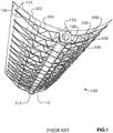
- the prior art system 100 includes a parabolic trough-shaped solar collector assembly including a plurality of mirror elements 102.
- a plurality of support arms comprising an upper tube 104 and a lower tube 106, which are interconnected by a plurality of lacing elements 108, are connected via inner ends of the upper tubes 104 and of the lower tubes 106 to an elongated central support element - torque tube 110.
- the upper tube 104 is connected to torque tube 110 via a not illustrated upper structure-attachment bracket
- the lower tube 106 is connected to torque tube 110 via lower structure-attachment bracket 112.
- the mirror elements 102 are supported, one relative to another, in position above the support arms via mirror-attachment brackets 114, which are mounted to the upper tube 104 at predetermined locations along the length thereof.
- a torque plate 116 is provided at each of the opposite ends of the torque tube 110 for transferring rotational motion from a not illustrated drive mechanism to the torque tube 110, for rotating the parabolic trough-shaped solar collector assembly about a longitudinal axis extending along the length of the torque tube 110. In this fashion, the prior art parabolic trough-shaped solar collector tracks the movement of the sun across the sky.
- the upper tubes 104, the lower tubes 106, and each of the lacing elements 108 are individually formed tubular structures. More particularly, the shape of the upper tubes 104 and of the lower tubes 106 are created either by bending sections of tubing that have been cut to length, or by welding together shorter tubular sections with angled ends so as to build the upper and lower tubes 104 and 106 with the desired shape. Further, each one of the individual lacing elements 108 must be cut to a specified length, to within very close tolerance, and must be positioned precisely during the process of assembling the supports arms. Very close tolerance and precise positioning of the lacing elements 108 is necessary, since each lacing element must be welded at one end to the upper tube 104 and at the other end to the lower tube 106.
- a trough-shaped solar collector When a trough-shaped solar collector is to be installed using the system 100 of FIG. 1 , a plurality of the support arms must be preassembled and then transported to the installation site, or they must be assembled at the installation site often under adverse working conditions. In either case, the resulting support system 100 is excessively heavy and often provides unsatisfactory rigidity. In addition, the system 100 cannot be easily modified for supporting trough-shaped solar collectors of varying size and/or shape, since any such modification involves redesigning a large number of components in order to ensure that all of the components fit together sufficiently closely to allow for welding together to form the support arms.
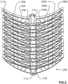
- FIG. 2 shown is a perspective view of a support system for supporting a trough-shaped solar concentrator assembly, according to an embodiment of the instant invention.
- the system 200 includes a parabolic trough-shaped solar collector assembly, including a plurality of mirror elements 202.
- a plurality of support arms, each comprising a first rail 204 and a second rail 206 interconnected by a plurality of web structures 208a-d, are coupled via inner ends of the first rails 204 and of the second rails 206 to an elongated central support element - torque tube 210.
- first rail 204 is connected to torque tube 210 via a not illustrated upper structure attachment bracket
- second rail 206 is connected to torque tube 210 via a lower structure attachment bracket 212.
- the mirror elements 202 are supported one-relative to another above the support arms via mirror attachment brackets 214, which are mounted to the first rail 204 at predetermined locations along the length thereof.
- a torque plate 216 is provided at each of the opposite ends of the torque tube 210 for transferring rotational motion from a not illustrated drive mechanism to the torque tube 210, for rotating the parabolic trough-shaped solar collector assembly about a longitudinal axis extending along the length of the torque tube 210. In this fashion, the supported trough-shaped solar concentrator assembly tracks the movement of the sun across the sky.
- each one of the first rail 204 and the second rail 206 in FIG. 3a has a cross-sectional profile of the type that is shown in greater detail in FIG. 4a .
- a pair of flanges protrudes from, and extends along the entire length of, the convexly curved side of the first rail 204 and the concavely curved side of the second rail 206.
- the pair of flanges which includes a first flange 402 and a second flange 404, provides spaced-apart facing surfaces that define an open channel structure for receiving therebetween the edge portions of the plurality of web structures 208a-d. Additionally, the surfaces of the first flange 402 and of the second flange 404 facilitate attachment of the web structures 208a-d to the first rail 204 and to the second rail 206, such as for instance by spot-welding or by riveting.
- the enlarged section that is shown within the dashed-oval in FIG. 3a shows, in greater detail, a pair of rivets 300 securing the web structure 208b to the flanges 402/404 of the second rail 206.
- Structure mounting brackets 212 and 218 are fixedly secured to the second rail 206 and to the first rail 204, respectively, such as by riveting or spot-welding.
- a plurality of mirror attachment brackets 214 are mounted at predetermined locations along the length of the first rail 204, such as by riveting or spot welding. In the specific example that is shown in FIG. 3a , a total of four mirror attachment brackets 214 are shown.
- a number of mirror attachment brackets 214 greater than or less than four is provided, in dependence upon the length of the first rail 204, the size of the trough-shaped solar collector being supported, etc.
- each one of the plurality of web structures 208a-d is shaped and sized differently than the other ones of the plurality of web structures 208a-d.
- the particular shape and size of each of the plurality of web structures 208a-d is determined based on the requirements of a particular application.
- the web structure 208a is larger in a spacing direction than the web structure 208b, which is larger in the spacing direction than the web structure 208c, which is larger in the spacing direction than the web structure 208d.
- the first and second rails 204 and 206, respectively, and the plurality of web structures 208a-d are fabricated from the same material, such as for instance high-strength steel.
- the plurality of web structures 208a-d is attached to the first and second rails 204 and 206, respectively, by one of welding, riveting or another suitable coupling mechanism.
- the first and second rails 204 and 206, respectively, and the plurality of web structures 208a-d are fabricated from different materials.
- the first and second rails 204 and 206, respectively, are fabricated from high-strength steel and the plurality of web structures 208a-d is fabricated from aluminum or an alloy thereof, or from a composite material, etc.
- composite materials include steel/plastic/steel sandwich materials or steel/paper/steel sandwich materials.
- the plurality of web structures 208a-d is attached to the first and second rails 204 and 206, respectively, using a suitable one of welding, riveting or another suitable coupling mechanism.
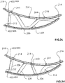
- FIG. 3b shows a side view of a support arm showing a first variation of the web structure design.
- the "V" shaped web structures 208a-c and the end web structure 208d of FIG. 3a are replaced by an extended "M” shaped web structure 302a and an extended “N” shaped web structure 302b. Attachment of the web structures 302a and 302b to the first and second rails 204 and 206, respectively, is accomplished as described above.
- FIG. 3c shows a side view of a support arm showing a second variation of the web structure design.
- the "V" shaped web structures 208a-c and the end web structure 208d of FIG. 3a are replaced by a single extended "M" shaped web structure 304. Attachment of the web structure 304 to the first and second rails 204 and 206, respectively, is accomplished as described above.
- FIG. 3d shows a side view of a support arm showing a third variation of the web structure design.
- the "V" shaped web structures 208a-c and the end web structure 208d of FIG. 3a are replaced by a plurality of straight-section web structures 306, 308 and 310 and a generally arc-shaped web structure 312. Attachment of the web structures 306, 308, 310 and 312 to the first and second rails 204 and 206, respectively, is accomplished as described above.
- FIG. 4a shows a first cross-sectional profile of the curved first and second rails, 204 and 206, respectively, of the support arm of FIGS. 3a-d .
- the profile includes a substantially rectangular portion 400 with two flanges 402 and 404 extending away from one side thereof.
- the two flanges 402 and 404 define an open channel structure 406 therebetween for receiving edge portions of the web structures 208a-d.
- the flanges 402 and 404 provide surfaces for fixedly securing the edge portions of the web structures 208a-d, such as by spot welding as shown in FIG. 5a or by riveting as shown in FIG. 5b .
- the first rails 204 and the second rails 206 are roll formed to produce non-curved rails having the profile shown that is shown in FIG. 4a .
- curvature is added to the non-curved rails in a sweep box, such that the flanges 402 and 404 are arranged along a resulting convexly curved side of the first rails 204 and along a resulting concavely curved side of the second rails 206.
- the dimensions indicated in FIG. 4a are provided by way of a specific and non-limiting example. In practice, the actual dimensions of the rail profile are selected based on the specific requirements of a particular application.
- the edge portions of one or more of the web structures that are shown in FIGS. 3b-c are received between the two flanges 402 and 404 in place of the web structures 208a-d.
- FIG. 4b shows a second cross-sectional profile of the first and second curved rails of the support arm of FIGS. 3a-d .
- the profile includes a substantially triangular portion 410 with two flanges 412 and 414 extending away from one apex thereof.
- the two flanges 412 and 414 define an open channel structure 416 therebetween for receiving edge portions of the web structures 208a-d.
- FIG. 4c shows a third cross-sectional profile of the first and second curved rails of the support arm of FIGS. 3a-d .
- the profile includes a substantially rectangular portion 420 with a single flange 422 extending away from a central portion of one side thereof.
- a small gap 424 adjacent to the flange 422 may be welded for added rigidity after the profile is formed.
- the flange 422 provides a surface for fixedly securing the edge portions of the web structures 208a-d, such as by spot welding or by riveting, etc.
- one or more of the web structures that are shown in FIGS. 3b-c are fixedly secured to the flange 422 in place of the web structures 208a-d.
- FIG. 4d shows a fourth cross-sectional profile of the first and second curved rails of the support arm of FIGS. 3a-d .
- the profile includes a substantially rectangular portion 430 with a single flange 432 extending away from an edge portion of one side thereof.
- a small gap 434 adjacent to the flange 432 may be welded for added rigidity after the profile is formed.
- the flange 432 provides a surface for fixedly securing the edge portions of the web structures 208a-d, such as by spot welding or by riveting, etc.
- one or more of the web structures that are shown in FIGS. 3b-c are fixedly secured to the flange 422 in place of the web structures 208a-d.
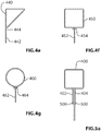
- FIG. 4e shows a fifth cross-sectional profile of the first and second curved rails of the support arm of FIGS. 3a-d .
- the profile includes a substantially right-triangular portion 440 with a single flange 442 extending away from an apex thereof.
- a small gap 444 adjacent to the flange 442 may be welded for added rigidity after the profile is formed.
- the flange 442 provides a surface for fixedly securing the edge portions of the web structures 208a-d, such as by spot welding or by riveting, etc.
- one or more of the web structures that are shown in FIGS. 3b-c are fixedly secured to the flange 422 in place of the web structures 208a-d.
- FIG. 4f shows a sixth cross-sectional profile of the first and second curved rails of the support arm of FIGS. 3a-d .
- the profile includes a substantially square or rectangular closed portion 450.
- the closed portion 450 optionally is roll formed and closed with a seam weld, or is extruded or hydroformed.
- a single flange 452 is fixedly secured to one side of the closed portion 450 and projects away therefrom at substantially a right angle. As is shown at 454 in FIG. 4f , the flange 452 is welded to the one side of the closed portion 450.
- the single flange extends along the length of the curved rail and provides a surface for fixedly securing the edge portions of the web structures 208a-d, such as by spot welding or by riveting, etc.
- one or more of the web structures that are shown in FIGS. 3b-c are fixedly secured to the flange 452 in place of the web structures 208a-d.
- FIG. 4g shows a fifth cross-sectional profile of the first and second curved rails of the support arm of FIGS. 3a-d .
- the profile includes a substantially circular closed portion 460.
- the closed portion 460 optionally is roll formed and closed with a seam weld, or is extruded or hydroformed.
- a single flange 462 is fixedly secured to the closed portion 460 and projects away therefrom at substantially a right angle. As is shown at 464 in FIG. 4g , the flange 462 is welded to the one side of the closed portion 460.
- the single flange extends along the length of the curved rail and provides a surface for fixedly securing the edge portions of the web structures 208a-d, such as by spot welding or by riveting, etc.
- one or more of the web structures that are shown in FIGS. 3b-c are fixedly secured to the flange 462 in place of the web structures 208a-d.
- FIG. 5a shows an end view in which an edge portion of a web structure 208a-d is received within an open channel structure that is formed along the convex side of the first rail 204 of the support arm of FIGS. 3a-d .
- Spot welds 500 fixedly secure the edge of the web structures 208a-d to surfaces of the flanges 402 and 404, which flanges protrude from the convex side of the first rail 204.
- one or more of the web structures that are shown in FIGS. 3b-c are fixedly secured to the flanges 402 and 404 in place of the web structures 208a-d.
- FIG. 5b shows an end view in which an edge portion of a web structure 208a-d is received within an open channel structure that is formed along the convex side of the first rail 204 of the support arm of FIGS. 3a-d .
- a rivet 502 fixedly secure the edge of the web structures 208a-d to surfaces of the flanges 402 and 404, which flanges protrude from the convex side of the first rail 204.
- one or more of the web structures that are shown in FIGS. 3b-c are fixedly secured to the flanges 402 and 404 in place of the web structures 208a-d.
- FIG. 6 shows a plurality of web structures, in this specific example web structures 208a-d, nested together after being stamped from a single blank.
- steel rule dies are used to stamp out the plurality of web structures 208a-d in a single press.
- different web structure shapes may be stamped in a similar fashion.
- FIG. 7 shows enlarged detail of a structure attachment bracket 218, which is mounted to the first end of the first curved rail 204 of the support arm of FIGS. 3a-d .
- the structure attachment bracket 218 is secured to the first curved rail 204 using a pair of rivets 700, one of which is not illustrated in FIG. 7 .
- the structure attachment bracket 218 includes through-holes 702 for receiving a mechanical fastener when the support arm is mounted to a support structure, such as for instance torque tube 210 of FIG. 2 .
- the structure attachment bracket 218 is fabricated from steel.
- FIG. 8 shows a mirror attachment bracket mounted proximate to the second end of the first curved rail of the support arm of FIGS. 3a-d .
- the mirror attachment bracket 214 is secured to the first curved rail 204 using a pair of rivets 800, one of which is not illustrated in FIG. 8 .
- the mirror attachment bracket 214 includes a through-hole 802 for receiving a mechanical fastener when the trough-shaped solar collector is mounted thereto.
- the structure attachment bracket 214 is fabricated from steel.
- the first rail 204, the second rail 206, the web structures such as 208a-d, the structure-attachment brackets 212 and 218 and the mirror-attachment brackets 214 may be fixtured to facilitate assembly.
- the system 200 that is illustrated in FIG. 2 is then assembled by attaching a plurality of support arms along both sides of the torque tube 210, via the structure-attachment brackets 212 and 218.
- the system 200 provides the same stiffness as the system 100 but with reduced weight, or alternatively the system 200 provides improved stiffness relative to the system 100 with the same weight.
- increased stiffness results in reduced deflection such that the structure is deformed to a lesser extent under the influence of gravity as the system tracks the sun during the course of the day, or when the system is subjected to high wind loads. Reduced deflection results in improved optical characteristics and accordingly higher efficiency.
- the system of FIG. 2 is more modular and more customizable than the prior art system of FIG. 1 .
- a system for supporting larger trough-shaped collector systems may be fabricated simply by roll-forming longer first and second rails 204 and 206, respectively, and by stamping a plurality of web structures that provide a support arm with desired inter-rail spacing between an inner end that is attached to a central torque tube, or to another suitable support structure, and an outer end that is opposite the inner end.
- two or more rail portions are joined together in an end-to-end fashion to form a first rail and two or more rail portions are joined together in an end-to-end fashion to form a second rail.
- the same tool may be used to roll-form rails that are nearly two times the length of the first and second rails 204 and 206, respectively, of the system 200.
- FIGS. 9, 10a-c and 11 illustrate the different degrees of adjustability that are present in the system of FIG. 2 .
- the flanges e.g. 402 and 404 protruding from the convex and concave sides of the first and second rails 204 and 206, respectively, provide surfaces for attaching the web structures to the rails.
- the edges of the web structures are overlapped with the flanges of the first and second rails, and are fixedly secured thereto by riveting, by welding, by toggle locking or by another suitable method.
- FIGS. 9, 10a-c and 11 each of the web structures (for clarity, only the web structures 208a-c are shown in FIGS.
- a slip plane 900 Prior to fixedly securing the web structures to the flanges of the first and second rails, an extent of overlap between the edge portions of the web structures and the flanges, and/or the location of the web structures along the length of the rails, can be adjusted within predetermined limits by moving the web structures vertically (indicted by the double-headed arrows in FIG. 9 ) and/or longitudinally (indicted by the double-headed arrows in FIG. 11 ), within "slip plane” 900.
- Adjusting the extent of the overlap between the edge portions of the web structures and the first and second flanges, and/or adjusting the location of the web structures along the length of the rails provides sufficient flexibility to compensate for cutting errors in the manufacture of the web structures, or to allow for a relatively small amount of modification to the geometry of the support arm. For instance, it may be possible to modify a particular support arm design by roll forming first and second rails that are up to at least 10% longer than the design calls for, and still be able to successfully interconnect the first and second rails without making any modifications to the web structures.
- the web structures may be attached to the longer rails with an increased spacing between the web structures compared to the spacing that is provided in the particular design, such as by adjusting the web structures longitudinally within "slip plane” 900.
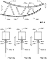
- the height of the support arm may be varied by adjusting the web structures "vertically" within "slip plane” 900, as is shown in greater detail in FIGS. 10a-c .
- FIGS. 10a-c shows the edge portion of one of the web structures 208a-d fixedly secured to the flanges 402 and 404 via spot welds 500.
- FIG. 10a-c shows the edge portion of one of the web structures 208a-d fixedly secured to the flanges 402 and 404 via spot welds 500.
- a support arm of intermediate height is formed in which the edge portions of the web structures 208a-d do not extend past the flanges 402 and 404 into the substantially rectangular portion 400 of the rail.
- a support arm of lesser height relative to 10a is formed in which the edge portions of the web structures 208a-d extend past the flanges 402 and 404 and into the substantially rectangular portion 400 of the rail.
- a support arm of greater height relative to 10a is formed in which the edge portions of the web structures 208a-d extend only partially into the opening that is formed between the flanges 402 and 404.
- the web structures may also be adjusted rotationally, relative to the rails, as required in order to facilitate making three points of attachment to the first and second rails 204 and 206, including at least one point of attachment to the first rail 204 and at least one point of attachment to the second rail 206.
- the prior art system 100 does not support this type of modification, including field modifications even under adverse conditions, since each of the lacing elements 108 must be cut precisely to length in order to be welded to the upper and lower tubes 104 and 106, respectively. There is no adjustable overlap in the prior art system 100, since the ends of the lacing elements 108 are butted up against the surfaces of the upper and lower tubes 104 and 106, respectively, and welded thereto.
- the web structures that are shown in FIGS. 3a-d may be secured to the flanges of the rails by riveting, instead of by welding, the use of different materials such as for instance steel for the rails and aluminum or composite materials for the web structures, is supported.
- the use of lightweight materials results in substantial weight reduction compared to the prior art system 100 of FIG. 1 .
- the use of flat web structures, such as the ones that are shown in FIGS. 3a-d instead of the prior art tubular members results in additional weight reduction compared to the system 100 of FIG. 1 .
- greater rigidity is achieved in the system 200 compared to the system 100 of the same weight.
Landscapes
- Engineering & Computer Science (AREA)
- Physics & Mathematics (AREA)
- Sustainable Development (AREA)
- Life Sciences & Earth Sciences (AREA)
- Sustainable Energy (AREA)
- Thermal Sciences (AREA)
- Chemical & Material Sciences (AREA)
- Combustion & Propulsion (AREA)
- Mechanical Engineering (AREA)
- General Engineering & Computer Science (AREA)
- Astronomy & Astrophysics (AREA)
- General Physics & Mathematics (AREA)
- Optics & Photonics (AREA)
- Photovoltaic Devices (AREA)
- Mounting And Adjusting Of Optical Elements (AREA)
Description
- The instant invention relates generally to solar energy collectors, and more particularly to a support system and method for trough-shaped solar energy concentrators.
- Concentrating Solar Power (CSP) systems utilize mirrors to concentrate the sun's energy onto points or lines. For instance, trough-shaped solar concentrators focus the sun's energy onto a fluid filed tube; the hot fluid is then transferred to a more conventional steam turbine power plant or similar system to generate electricity. One specific and non-limiting example utilizes a trough that is parabolic in a cross section taken in a plane that is normal to the length of the trough. With the assistance of a tracking system, parabolic trough collectors are very efficient as they follow the movement of the sun during the course of a day. For simplicity, the following discussion refers to parabolic troughs and parabolic mirrors. Of course, other suitable shapes are known.
- As solar energy collector apparatuses incorporating parabolic type collectors are now being required to satisfy ever-larger energy requirements, they necessarily become physically larger. In some apparatuses, the aggregate collector surface may typically approach thousands of square meters. Consequently, reliable support for the large parabolic mirrors is critical to ensure excellent performance (focus) in varying atmospheric conditions and to guard against mirror breakage. Some of the key issues include overall frame deflection from its own weight, and that of the attached mirrors and wind loads. Prior art frames for solar trough designs relied on steel fabrications and weldments or aluminum extrusions configured and joined using techniques developed in the building construction industry. Such techniques require pre-assembly and transportation of large frame sections, often to locations that are difficult to access, or they require labor intensive assembly of components on-site, often under unfavorable conditions.
-
U.S. Patent No. 4,423,719 discloses a parabolic trough solar energy collector that is fabricated without the need for any blind fasteners or blind fastening devices. An integrated parabolic solar energy collector is provided which can be welded or fastened with spot welds, seam welds, rivets, bolts or the like. -
U.S. Patent No. 4,135,493 discloses a parabolic trough solar energy collector including an elongated support with a plurality of ribs secured thereto and extending outwardly therefrom. One surface of the ribs is shaped to define a parabola and is adapted to receive and support a thin reflecting sheet, which forms a parabolic trough-shaped reflecting surface. One or more of the collectors is adapted to be joined end-to-end, and supported for joint rotation to track the sun. -
U.S. Patent Application Publication No. 2010/0050560 discloses a parabolic trough solar energy collector frame including a plurality of chords. The frame comprises a plurality of extruded profiles, including chord sleeves, struts and strut end pieces, each chord sleeve having at least one chord sleeve fin, each chord sleeve positioned about one of the chords. The frame comprises a plurality of struts, at least one of the struts having a strut end piece having at least one strut end piece fin that connects with a chord sleeve fin to connect the plurality of chords. The frame comprises a platform supported by the chords and struts, on which the solar mirrors are disposed. -
PCT Publication WO 2010/078004 discloses a solar energy collector apparatus comprising a solar collector panel having a parabolic shape, and a base comprising a pair of spaced apart support frames. Each support frame has a parabolic shape, which corresponds to the parabolic shape of the solar collector panel. Spaced apart rollers may be positioned along an upper surface of each support frame to support the solar collector panel. A drive mechanism may be coupled to the solar collector panel for rotation thereof. The solar collector panel may include a pair of spaced apart rollers to ensure that the solar collector panel rotates squarely with respect to the base.ES 1 070 880 - Unfortunately, even in view of the systems that have been discussed in the preceding paragraphs, there still exists a need for a simplified support system and method for use with trough-shaped solar energy concentrators. It would therefore be advantageous to provide a system and a method that overcomes at least some of the limitations of the prior art.
- A support arm for a trough-shaped solar collector assembly, comprises:
- a first rail having a length that extends between first and second opposite ends thereof and having a curvature extending along the length and defining a convex side of the first rail, the convex side forming a first open channel-structure that extends between the first end and the second end of the first rail; a second rail having a length that extends between first and second opposite ends thereof and having a curvature extending along the length and defining a concave side of the second rail, the concave side forming a second open channel-structure that extends between the first end and the second end of the second rail; and, a plurality of web structures interconnecting the first rail and the second rail, the plurality of web structures including a first web structure having a size that is defined along a spacing direction between opposite edges thereof and that is larger than a size that is defined along the spacing direction between opposite edges of a second web structure of the plurality of web structures, wherein one of the opposite edges of the first web structure and one of the opposite edges of the second web structure is received within the first open channel-structure of the first rail, and the other of the opposite edges of the first web structure and the other of the opposite edges of the second web structure is received within the second open channel-structure of the second rail, the first web structure disposed proximate the first ends of the first and second rails and the second web structure disposed proximate the second ends of the first and second rails, such that the second ends of the first and second rails are spaced more closely together than the first ends of the first and second rails when the support arm is in an assembled condition.
- A support arm for a trough-shaped solar collector assembly, comprises: a first rail that is curved in a direction along a length thereof and having a concave side for supporting a solar collector element and having a convex side that is opposite the concave side, a first flange protruding from the convex side of the first rail and extending along the length thereof; a second rail that is curved in a direction along a length thereof and having a concave side, a second flange protruding from the concave side of the second rail and extending along the length thereof, the second rail disposed in a spaced-apart relationship with the first rail such that the first and second flanges are approximately aligned one with the other and extend one toward the other; and, a plurality of web structures interconnecting the first rail and the second rail, the plurality of web structures including a first web structure having a size that is defined along a spacing direction between opposite edges thereof and that is larger than a size that is defined along the spacing direction between opposite edges of a second web structure of the plurality of web structures, wherein one of the opposite edges of the first web structure and one of the opposite edges of the second web structure is fixedly secured to the first flange of the first rail, and the other of the opposite edges of the first web structure and the other of the opposite edges of the second web structure is fixedly secured to the second flange of the second rail, the first web structure disposed proximate the first ends of the first and second rails and the second web structure disposed proximate the second ends of the first and second rails, such that the second ends of the first and second rails are spaced more closely together than the first ends of the first and second rails when the support arm is in an assembled condition
- According to an aspect of one embodiment of the instant invention, there is provided a support system for a trough-shaped solar collector assembly, comprising: a plurality of support arms, each support arm comprising: a first rail that is curved in a direction along a length thereof and having a concave side for supporting a solar collector element and having a convex side that is opposite the concave side, the convex side of the first rail forming a first web-engaging structure; a second rail that is curved in a direction along a length thereof and having a concave side forming a second web-engaging structure, the second rail disposed in a spaced-apart relationship with the first rail such that the first web-engaging structure faces the second web-engaging structure; and, a plurality of web structures fixedly secured to the first and second rails via the first web-engaging structure and the second web-engaging structure, respectively, including a first web structure disposed proximate the first ends of the first and second rails and creating a first spacing therebetween, and a second web structure disposed proximate the second ends of the first and second rails and creating a second spacing therebetween, the second spacing smaller than the first spacing; structure-attachment brackets mounted one each to the first ends of the first and second rails for attaching the support arm to a structure; and, a plurality of mirror-attachment brackets mounted to the concave side of the first rail, for securing the trough-shaped solar collector assembly to the support arm, wherein the first and second web-engaging structures comprise flanges that provide surfaces for attaching the web structures to the rails, and prior to fixedly securing the web structures to the flanges, an extent of overlap between edge portions of the web structures and the flanges and the location of the web structures along the length of the rails can be adjusted within predetermined limits by moving the web structures vertically and longitudinally within a common plane.
- According to an aspect of one embodiment of the instant invention, there is provided a method for supporting a trough-shaped solar collector assembly, comprising: for each support arm of a plurality of support arms: aligning first edge portions of each one of a plurality of web structures with a first web engaging structure extending along a first side of a first rail, the first rail being curved in a direction along a length thereof and the first side being convexly curved along the length; aligning second edge portions that are opposite the first edge portions of each one of the plurality of web structures with a second web engaging structure extending along a first side of a second rail, the second rail being curved in a direction along a length thereof and the first side being concavely curved along the length; fixedly securing the first edge portions of each one of the plurality of web structures to the first web engaging structure and fixedly securing the second edge portions of each one of the plurality of web structures to the second web engaging structure, so as to rigidly interconnect the first and second rails and so that an inter-rail spacing increases between a first end of the support arm and a second end of the support arm, the second end opposite the first end; attaching the first end of each one of the plurality of support arms to a support structure via a pair of structure attachment brackets mounted one each to the first rail and to the second rail at the first end of each one of the plurality of support arms; and, attaching the trough-shaped solar collector assembly to the plurality of support arms via attachment brackets mounted adjacent to a second side of the first rail that is opposite the first side of the first rail, further comprising prior to fixedly securing, supporting the first rail relative to the second rail such that the web engaging structures, which comprise flanges that provide surfaces for attaching the web structures to the rails, are approximately aligned one with the other and extend toward the other, and adjusting within predetermined limits an extent of overlap between the first edge portions and the first web engaging structure and an extent of overlap between the second edge portions and the second web engaging structure by moving the web structures vertically and longitudinally within a common plane.
- A method for supporting a trough-shaped solar collector assembly, the trough-shaped solar collector assembly extending along a length and having a collector element array that extends outwardly a known distance in both directions from a center-line thereof and that defines a known curvature in a direction transverse to the length, comprising: forming a plurality of first rails each having a first length that is selected in dependence upon the known distance, each first rail having a first web-engaging structure defined along one side thereof; forming a plurality of second rails each having a second length that is selected in dependence upon the known distance, each second rail having a second web-engaging structure defined along one side thereof; sweeping each one of the plurality of first rails to provide a curvature extending along the first length, the curvature selected in dependence upon the known curvature of the collector element array, such that the first web-engaging structure is defined along a side of the curved first rail that is convex in a direction along the first length; sweeping each one of the plurality of second rails to provide a curvature extending along the second length, the curvature selected in dependence upon the known curvature of the collector element array, such that the web-engaging structure is defined along a side of the curved second rail that is concave in a direction along the second length; forming a plurality of web-structures for being disposed between a curved first rail and a curved second rail, the plurality of web-structures being sized such that when the curved first rail and the curved second rail are interconnected by the plurality of web structures, second ends of the curved first and second rails are spaced more closely together than first ends of the curved first and second rails; attaching each interconnected pair of curved first and second rails via the first ends thereof to a central support structure that is aligned with the center-line of the trough-shaped solar collector assembly; and, attaching the collector element array to the interconnected pairs of curved first and second rails via attachment brackets carried by the curved first rails.
- A method for supporting a trough-shaped solar collector assembly, comprising: providing a first rail having a first length, the first rail curved in a direction along the first length and having a first flange protruding from a side thereof that is curved convexly in a direction along the first length; providing a second rail having a second length, the second rail curved in a direction along the second length and having a second flange protruding from a side thereof that is curved concavely in a direction along the second length; supporting the first rail relative to the second rail such that the first and second flanges are approximately aligned one with the other and extend one toward the other; overlapping a first edge portion of a web structure with the first flange and overlapping a second edge portion of the web structure with the second flange, the first and second edge portions spaced-apart one from the other along a spacing direction; adjusting at least one of an extent of overlap between the first edge portion and the first flange and an extent of overlap between the second edge portion and the second flange, so as to define a first arrangement of the first and second rails and the web structure; and, fixedly securing the first edge portion of the web structure to the first rail via the first flange and fixedly securing the second edge portion of the web structure to the second rail via the second flange while maintaining the defined first arrangement thereof.
- A field-adjustable support system for a trough-shaped solar collector assembly, comprising: first and second continuously curved rails for being disposed in a spaced-apart arrangement one relative to the other, each rail having a length extending between first and second opposite ends thereof; a web structure for being disposed between and for interconnecting the first and second continuously curved rails, the web structure configured for making at least three points of attachment to the first and second continuously curved rails including at least one point of attachment to the first continuously curved rail and one point of attachment to the second continuously curved rail; wherein prior to fixedly securing the web structure to the first and second continuously curved rails, at least one of the location and the orientation of the web structure is adjustable for supporting interconnection of the first and second continuously curved rails with different rates of convergence between a maximum inter-rail separation between the first ends of the first and second continuously curved rails and a minimum inter-rail separation between the second ends of the first and second continuously curved rails.
- Exemplary embodiments of the instant invention will now be described in conjunction with the following drawings, wherein like reference numerals refer to similar or identical parts throughout the several views, in which:
-
FIG. 1 is a perspective view showing a prior art support system for a trough-shaped solar concentrator assembly; -
FIG. 2 is a perspective view showing a support system for a trough-shaped solar concentrator assembly comprising a plurality of support arms, according to an embodiment of the instant invention; -
FIG. 3a is a side view of a support arm of the support system ofFIG. 2 ; -
FIG. 3b is a side view of a support arm showing a first variation of the web structure design; -
FIG. 3c is a side view of a support arm showing a second variation of the web structure design; -
FIG. 3d is a side view of a support arm showing a third variation of the web structure design; -
FIG. 4a shows a first cross-sectional profile of the first and second curved rails of the support arm ofFIGS. 3a-d ; -
FIG. 4b shows a second cross-sectional profile of the first and second curved rails of the support arm ofFIGS. 3a-d ; -
FIG. 4c shows a third cross-sectional profile of the first and second curved rails of the support arm ofFIGS. 3a-d ; -
FIG. 4d shows a fourth cross-sectional profile of the first and second curved rails of the support arm ofFIGS. 3a-d ; -
FIG. 4e shows a fifth cross-sectional profile of the first and second curved rails of the support arm ofFIGS. 3a-d ; -
FIG. 4f shows a sixth cross-sectional profile of the first and second curved rails of the support arm ofFIGS. 3a-d ; -
FIG. 4g shows a seventh cross-sectional profile of the first and second curved rails of the support arm ofFIGS. 3a-d ; -
FIG. 5a shows an edge portion of a web structure received within an open channel structure that is formed along the convex side of the first rail of the support arm ofFIGS. 3a-d , the edge of the web structure spot welded to flanges protruding from the convex side; -
FIG. 5b shows an edge portion of a web structure received within an open channel structure that is formed along the convex side of the first rail of the support arm ofFIGS. 3a-d , the edge of the web structure riveted to flanges protruding from the convex side; -
FIG. 6 shows a plurality of web structures nested together after being stamped from a single blank; -
FIG. 7 shows a structure-attachment bracket mounted to the first end of the first curved rail of the support arm ofFIGS. 3a-d ; -
FIG. 8 shows a mirror-attachment bracket mounted proximate to the second end of the first curved rail of the support arm ofFIGS. 3a-d ; -
FIG. 9 is an exploded side view showing three web structures disposed within a common "slip plane" between the first and second rails of a support arm according to an embodiment of the instant invention, with "vertical" adjustability indicated; -
FIGS. 10a-c shows an edge portion of a web structure fixedly secured between the flanges of one of the first and second rails of a support arm according to an embodiment of the instant invention, at three different respective vertical positions within the "slip plane". -
FIG. 11 is an exploded side view showing three web structures disposed within a common "slip plane" between first and second rails of a support arm according to an embodiment of the instant invention, with "longitudinal" adjustability indicated. - The following description is presented to enable a person skilled in the art to make and use the invention, and is provided in the context of a particular application and its requirements. Various modifications to the disclosed embodiments will be readily apparent to those skilled in the art, and the general principles defined herein may be applied to other embodiments and applications without departing from the scope of the invention. Thus, the present invention is not intended to be limited to the embodiments disclosed, but is to be accorded the widest scope consistent with the principles and features disclosed herein. The term "vertically" should be understood to mean a reference direction extending between the top and bottom of a drawing, and the term "longitudinally" should be understood to mean a reference direction extending between the left and right sides across a drawing.
- In order to facilitate a better understanding of the features that are present in at least some of the embodiments of the instant invention, a prior art system is described herein below, with reference to
FIG. 1 . Theprior art system 100 includes a parabolic trough-shaped solar collector assembly including a plurality ofmirror elements 102. A plurality of support arms comprising anupper tube 104 and alower tube 106, which are interconnected by a plurality of lacingelements 108, are connected via inner ends of theupper tubes 104 and of thelower tubes 106 to an elongated central support element -torque tube 110. In particular, theupper tube 104 is connected totorque tube 110 via a not illustrated upper structure-attachment bracket, and thelower tube 106 is connected totorque tube 110 via lower structure-attachment bracket 112. Themirror elements 102 are supported, one relative to another, in position above the support arms via mirror-attachment brackets 114, which are mounted to theupper tube 104 at predetermined locations along the length thereof. Atorque plate 116 is provided at each of the opposite ends of thetorque tube 110 for transferring rotational motion from a not illustrated drive mechanism to thetorque tube 110, for rotating the parabolic trough-shaped solar collector assembly about a longitudinal axis extending along the length of thetorque tube 110. In this fashion, the prior art parabolic trough-shaped solar collector tracks the movement of the sun across the sky. - In the
system 100, theupper tubes 104, thelower tubes 106, and each of thelacing elements 108 are individually formed tubular structures. More particularly, the shape of theupper tubes 104 and of thelower tubes 106 are created either by bending sections of tubing that have been cut to length, or by welding together shorter tubular sections with angled ends so as to build the upper andlower tubes individual lacing elements 108 must be cut to a specified length, to within very close tolerance, and must be positioned precisely during the process of assembling the supports arms. Very close tolerance and precise positioning of thelacing elements 108 is necessary, since each lacing element must be welded at one end to theupper tube 104 and at the other end to thelower tube 106. Even relatively small cutting errors or positioning errors can result in difficulty during the fixturing and assembly of the components of the support arms. Further, since a large number of individual tubular structures are welded together to form the support arms, the assembly ofsystem 100 winds up being a very labor-intensive process. - When a trough-shaped solar collector is to be installed using the
system 100 ofFIG. 1 , a plurality of the support arms must be preassembled and then transported to the installation site, or they must be assembled at the installation site often under adverse working conditions. In either case, the resultingsupport system 100 is excessively heavy and often provides unsatisfactory rigidity. In addition, thesystem 100 cannot be easily modified for supporting trough-shaped solar collectors of varying size and/or shape, since any such modification involves redesigning a large number of components in order to ensure that all of the components fit together sufficiently closely to allow for welding together to form the support arms. - Referring now to
FIG. 2 , shown is a perspective view of a support system for supporting a trough-shaped solar concentrator assembly, according to an embodiment of the instant invention. Thesystem 200 includes a parabolic trough-shaped solar collector assembly, including a plurality ofmirror elements 202. A plurality of support arms, each comprising afirst rail 204 and asecond rail 206 interconnected by a plurality ofweb structures 208a-d, are coupled via inner ends of thefirst rails 204 and of thesecond rails 206 to an elongated central support element -torque tube 210. In particular, thefirst rail 204 is connected totorque tube 210 via a not illustrated upper structure attachment bracket, and thesecond rail 206 is connected totorque tube 210 via a lowerstructure attachment bracket 212. Themirror elements 202 are supported one-relative to another above the support arms viamirror attachment brackets 214, which are mounted to thefirst rail 204 at predetermined locations along the length thereof. Atorque plate 216 is provided at each of the opposite ends of thetorque tube 210 for transferring rotational motion from a not illustrated drive mechanism to thetorque tube 210, for rotating the parabolic trough-shaped solar collector assembly about a longitudinal axis extending along the length of thetorque tube 210. In this fashion, the supported trough-shaped solar concentrator assembly tracks the movement of the sun across the sky. - Referring now to
FIG. 3a , shown is a side view of a support arm of the support system that is shown inFIG. 2 . By way of a specific and non-limiting example, each one of thefirst rail 204 and thesecond rail 206 inFIG. 3a has a cross-sectional profile of the type that is shown in greater detail inFIG. 4a . In particular, a pair of flanges protrudes from, and extends along the entire length of, the convexly curved side of thefirst rail 204 and the concavely curved side of thesecond rail 206. The pair of flanges, which includes afirst flange 402 and asecond flange 404, provides spaced-apart facing surfaces that define an open channel structure for receiving therebetween the edge portions of the plurality ofweb structures 208a-d. Additionally, the surfaces of thefirst flange 402 and of thesecond flange 404 facilitate attachment of theweb structures 208a-d to thefirst rail 204 and to thesecond rail 206, such as for instance by spot-welding or by riveting. The enlarged section that is shown within the dashed-oval inFIG. 3a shows, in greater detail, a pair ofrivets 300 securing theweb structure 208b to theflanges 402/404 of thesecond rail 206. -
Structure mounting brackets second rail 206 and to thefirst rail 204, respectively, such as by riveting or spot-welding. In addition, a plurality ofmirror attachment brackets 214 are mounted at predetermined locations along the length of thefirst rail 204, such as by riveting or spot welding. In the specific example that is shown inFIG. 3a , a total of fourmirror attachment brackets 214 are shown. Optionally, a number ofmirror attachment brackets 214 greater than or less than four is provided, in dependence upon the length of thefirst rail 204, the size of the trough-shaped solar collector being supported, etc. - Referring still to
FIG. 3a , each one of the plurality ofweb structures 208a-d is shaped and sized differently than the other ones of the plurality ofweb structures 208a-d. The particular shape and size of each of the plurality ofweb structures 208a-d is determined based on the requirements of a particular application. In general terms, theweb structure 208a is larger in a spacing direction than theweb structure 208b, which is larger in the spacing direction than theweb structure 208c, which is larger in the spacing direction than theweb structure 208d. When in the assembled condition, first ends of the first andsecond rails second rails - According to at least one embodiment, the first and
second rails web structures 208a-d are fabricated from the same material, such as for instance high-strength steel. In this case, the plurality ofweb structures 208a-d is attached to the first andsecond rails - According to at least one embodiment, the first and
second rails web structures 208a-d are fabricated from different materials. For instance, the first andsecond rails web structures 208a-d is fabricated from aluminum or an alloy thereof, or from a composite material, etc. Some examples of composite materials include steel/plastic/steel sandwich materials or steel/paper/steel sandwich materials. Depending on the specific combination of materials that is used, the plurality ofweb structures 208a-d is attached to the first andsecond rails -
FIG. 3b shows a side view of a support arm showing a first variation of the web structure design. In particular, the "V" shapedweb structures 208a-c and theend web structure 208d ofFIG. 3a are replaced by an extended "M" shapedweb structure 302a and an extended "N" shapedweb structure 302b. Attachment of theweb structures second rails -
FIG. 3c shows a side view of a support arm showing a second variation of the web structure design. In particular, the "V" shapedweb structures 208a-c and theend web structure 208d ofFIG. 3a are replaced by a single extended "M" shapedweb structure 304. Attachment of theweb structure 304 to the first andsecond rails -
FIG. 3d shows a side view of a support arm showing a third variation of the web structure design. In particular, the "V" shapedweb structures 208a-c and theend web structure 208d ofFIG. 3a are replaced by a plurality of straight-section web structures web structure 312. Attachment of theweb structures second rails -
FIG. 4a shows a first cross-sectional profile of the curved first and second rails, 204 and 206, respectively, of the support arm ofFIGS. 3a-d . In particular, the profile includes a substantiallyrectangular portion 400 with twoflanges flanges open channel structure 406 therebetween for receiving edge portions of theweb structures 208a-d. In addition, theflanges web structures 208a-d, such as by spot welding as shown inFIG. 5a or by riveting as shown inFIG. 5b . By way of a specific and non-limiting example, thefirst rails 204 and thesecond rails 206 are roll formed to produce non-curved rails having the profile shown that is shown inFIG. 4a . After roll forming the profile, curvature is added to the non-curved rails in a sweep box, such that theflanges first rails 204 and along a resulting concavely curved side of the second rails 206. The dimensions indicated inFIG. 4a are provided by way of a specific and non-limiting example. In practice, the actual dimensions of the rail profile are selected based on the specific requirements of a particular application. Optionally, the edge portions of one or more of the web structures that are shown inFIGS. 3b-c are received between the twoflanges web structures 208a-d. -
FIG. 4b shows a second cross-sectional profile of the first and second curved rails of the support arm ofFIGS. 3a-d . In particular, the profile includes a substantiallytriangular portion 410 with twoflanges flanges open channel structure 416 therebetween for receiving edge portions of theweb structures 208a-d. -
FIG. 4c shows a third cross-sectional profile of the first and second curved rails of the support arm ofFIGS. 3a-d . In particular, the profile includes a substantiallyrectangular portion 420 with asingle flange 422 extending away from a central portion of one side thereof. Asmall gap 424 adjacent to theflange 422 may be welded for added rigidity after the profile is formed. Theflange 422 provides a surface for fixedly securing the edge portions of theweb structures 208a-d, such as by spot welding or by riveting, etc. Optionally, one or more of the web structures that are shown inFIGS. 3b-c are fixedly secured to theflange 422 in place of theweb structures 208a-d. -
FIG. 4d shows a fourth cross-sectional profile of the first and second curved rails of the support arm ofFIGS. 3a-d . In particular, the profile includes a substantiallyrectangular portion 430 with asingle flange 432 extending away from an edge portion of one side thereof. Asmall gap 434 adjacent to theflange 432 may be welded for added rigidity after the profile is formed. Theflange 432 provides a surface for fixedly securing the edge portions of theweb structures 208a-d, such as by spot welding or by riveting, etc. Optionally, one or more of the web structures that are shown inFIGS. 3b-c are fixedly secured to theflange 422 in place of theweb structures 208a-d. -
FIG. 4e shows a fifth cross-sectional profile of the first and second curved rails of the support arm ofFIGS. 3a-d . In particular, the profile includes a substantially right-triangular portion 440 with asingle flange 442 extending away from an apex thereof. Asmall gap 444 adjacent to theflange 442 may be welded for added rigidity after the profile is formed. Theflange 442 provides a surface for fixedly securing the edge portions of theweb structures 208a-d, such as by spot welding or by riveting, etc. Optionally, one or more of the web structures that are shown inFIGS. 3b-c are fixedly secured to theflange 422 in place of theweb structures 208a-d. -
FIG. 4f shows a sixth cross-sectional profile of the first and second curved rails of the support arm ofFIGS. 3a-d . In particular, the profile includes a substantially square or rectangularclosed portion 450. Theclosed portion 450 optionally is roll formed and closed with a seam weld, or is extruded or hydroformed. Asingle flange 452 is fixedly secured to one side of theclosed portion 450 and projects away therefrom at substantially a right angle. As is shown at 454 inFIG. 4f , theflange 452 is welded to the one side of theclosed portion 450. The single flange extends along the length of the curved rail and provides a surface for fixedly securing the edge portions of theweb structures 208a-d, such as by spot welding or by riveting, etc. Optionally, one or more of the web structures that are shown inFIGS. 3b-c are fixedly secured to theflange 452 in place of theweb structures 208a-d. -
FIG. 4g shows a fifth cross-sectional profile of the first and second curved rails of the support arm ofFIGS. 3a-d . In particular, the profile includes a substantially circularclosed portion 460. Theclosed portion 460 optionally is roll formed and closed with a seam weld, or is extruded or hydroformed. Asingle flange 462 is fixedly secured to theclosed portion 460 and projects away therefrom at substantially a right angle. As is shown at 464 inFIG. 4g , theflange 462 is welded to the one side of theclosed portion 460. The single flange extends along the length of the curved rail and provides a surface for fixedly securing the edge portions of theweb structures 208a-d, such as by spot welding or by riveting, etc. Optionally, one or more of the web structures that are shown inFIGS. 3b-c are fixedly secured to theflange 462 in place of theweb structures 208a-d. -
FIG. 5a shows an end view in which an edge portion of aweb structure 208a-d is received within an open channel structure that is formed along the convex side of thefirst rail 204 of the support arm ofFIGS. 3a-d .Spot welds 500 fixedly secure the edge of theweb structures 208a-d to surfaces of theflanges first rail 204. Optionally, one or more of the web structures that are shown inFIGS. 3b-c are fixedly secured to theflanges web structures 208a-d. -
FIG. 5b shows an end view in which an edge portion of aweb structure 208a-d is received within an open channel structure that is formed along the convex side of thefirst rail 204 of the support arm ofFIGS. 3a-d . Arivet 502 fixedly secure the edge of theweb structures 208a-d to surfaces of theflanges first rail 204. Optionally, one or more of the web structures that are shown inFIGS. 3b-c are fixedly secured to theflanges web structures 208a-d. -
FIG. 6 shows a plurality of web structures, in this specificexample web structures 208a-d, nested together after being stamped from a single blank. By way of a specific and non-limiting example, steel rule dies are used to stamp out the plurality ofweb structures 208a-d in a single press. Of course, different web structure shapes may be stamped in a similar fashion. -
FIG. 7 shows enlarged detail of astructure attachment bracket 218, which is mounted to the first end of the firstcurved rail 204 of the support arm ofFIGS. 3a-d . In the instant example, thestructure attachment bracket 218 is secured to the firstcurved rail 204 using a pair ofrivets 700, one of which is not illustrated inFIG. 7 . Thestructure attachment bracket 218 includes through-holes 702 for receiving a mechanical fastener when the support arm is mounted to a support structure, such as forinstance torque tube 210 ofFIG. 2 . By way of a specific and non-limiting example, thestructure attachment bracket 218 is fabricated from steel. -
FIG. 8 shows a mirror attachment bracket mounted proximate to the second end of the first curved rail of the support arm ofFIGS. 3a-d . In the instant example, themirror attachment bracket 214 is secured to the firstcurved rail 204 using a pair ofrivets 800, one of which is not illustrated inFIG. 8 . Themirror attachment bracket 214 includes a through-hole 802 for receiving a mechanical fastener when the trough-shaped solar collector is mounted thereto. By way of a specific and non-limiting example, thestructure attachment bracket 214 is fabricated from steel. - The
first rail 204, thesecond rail 206, the web structures such as 208a-d, the structure-attachment brackets attachment brackets 214 may be fixtured to facilitate assembly. Thesystem 200 that is illustrated inFIG. 2 is then assembled by attaching a plurality of support arms along both sides of thetorque tube 210, via the structure-attachment brackets system 200 provides the same stiffness as thesystem 100 but with reduced weight, or alternatively thesystem 200 provides improved stiffness relative to thesystem 100 with the same weight. Of course, increased stiffness results in reduced deflection such that the structure is deformed to a lesser extent under the influence of gravity as the system tracks the sun during the course of the day, or when the system is subjected to high wind loads. Reduced deflection results in improved optical characteristics and accordingly higher efficiency. - The system of
FIG. 2 is more modular and more customizable than the prior art system ofFIG. 1 . For instance, a system for supporting larger trough-shaped collector systems may be fabricated simply by roll-forming longer first andsecond rails second rails system 200. -
FIGS. 9, 10a-c and11 illustrate the different degrees of adjustability that are present in the system ofFIG. 2 . As discussed above, the flanges (e.g. 402 and 404) protruding from the convex and concave sides of the first andsecond rails FIGS. 9, 10a-c and11 each of the web structures (for clarity, only theweb structures 208a-c are shown inFIGS. 9 and11 ) are disposed within a common plane, referred to as a "slip plane" 900. Prior to fixedly securing the web structures to the flanges of the first and second rails, an extent of overlap between the edge portions of the web structures and the flanges, and/or the location of the web structures along the length of the rails, can be adjusted within predetermined limits by moving the web structures vertically (indicted by the double-headed arrows inFIG. 9 ) and/or longitudinally (indicted by the double-headed arrows inFIG. 11 ), within "slip plane" 900. - Adjusting the extent of the overlap between the edge portions of the web structures and the first and second flanges, and/or adjusting the location of the web structures along the length of the rails, provides sufficient flexibility to compensate for cutting errors in the manufacture of the web structures, or to allow for a relatively small amount of modification to the geometry of the support arm. For instance, it may be possible to modify a particular support arm design by roll forming first and second rails that are up to at least 10% longer than the design calls for, and still be able to successfully interconnect the first and second rails without making any modifications to the web structures. In particular, the web structures may be attached to the longer rails with an increased spacing between the web structures compared to the spacing that is provided in the particular design, such as by adjusting the web structures longitudinally within "slip plane" 900. Additionally, the height of the support arm may be varied by adjusting the web structures "vertically" within "slip plane" 900, as is shown in greater detail in
FIGS. 10a-c . Each one ofFIGS. 10a-c shows the edge portion of one of theweb structures 208a-d fixedly secured to theflanges FIG. 10a , a support arm of intermediate height is formed in which the edge portions of theweb structures 208a-d do not extend past theflanges rectangular portion 400 of the rail. InFIG. 10b , a support arm of lesser height relative to 10a is formed in which the edge portions of theweb structures 208a-d extend past theflanges rectangular portion 400 of the rail. InFIG. 10c , a support arm of greater height relative to 10a is formed in which the edge portions of theweb structures 208a-d extend only partially into the opening that is formed between theflanges - The web structures may also be adjusted rotationally, relative to the rails, as required in order to facilitate making three points of attachment to the first and
second rails first rail 204 and at least one point of attachment to thesecond rail 206. Theprior art system 100 does not support this type of modification, including field modifications even under adverse conditions, since each of thelacing elements 108 must be cut precisely to length in order to be welded to the upper andlower tubes prior art system 100, since the ends of thelacing elements 108 are butted up against the surfaces of the upper andlower tubes - Additionally, since the web structures that are shown in
FIGS. 3a-d may be secured to the flanges of the rails by riveting, instead of by welding, the use of different materials such as for instance steel for the rails and aluminum or composite materials for the web structures, is supported. The use of lightweight materials results in substantial weight reduction compared to theprior art system 100 ofFIG. 1 . Further, the use of flat web structures, such as the ones that are shown inFIGS. 3a-d , instead of the prior art tubular members results in additional weight reduction compared to thesystem 100 ofFIG. 1 . Alternatively, greater rigidity is achieved in thesystem 200 compared to thesystem 100 of the same weight. - Numerous other embodiments may be envisaged without departing from the scope of the instant invention.
Claims (14)
- A support system for a trough-shaped solar collector assembly, comprising:a plurality of support arms, each support arm comprising:a first rail (204) that is curved in a direction along a length thereof and having a concave side for supporting a solar collector element and having a convex side that is opposite the concave side, the convex side of the first rail forming a first web-engaging structure;a second rail (206) that is curved in a direction along a length thereof and having a concave side forming a second web-engaging structure, the second rail disposed in a spaced-apart relationship with the first rail such that the first web-engaging structure faces the second web-engaging structure;a plurality of web structures (208a-d, 302a-b, 304, 306, 308, 310, 312) fixedly secured to the first and second rails via the first web-engaging structure and the second web-engaging structure, respectively, including a first web structure (208a, 302a, 306) disposed proximate the first ends of the first and second rails and creating a first spacing therebetween, and a second web structure (208d, 302b, 312) disposed proximate the second ends of the first and second rails and creating a second spacing therebetween, the second spacing smaller than the first spacing;structure-attachment brackets (212, 218) mounted one each to the first ends of the first and second rails for attaching the support arm to a structure; and,a plurality of mirror-attachment brackets (214) mounted to the concave side of the first rail (204), for securing the trough-shaped solar collector assembly to the support arm,wherein the first and second web-engaging structures comprise flanges (402, 404, 412, 414, 422, 432, 452, 462) that provide surfaces for attaching the web structures (208a-d, 302a-b, 304, 306, 308, 310, 312) to the rails, and wherein prior to fixedly securing the web structures (208a-d, 302a-b, 304, 306, 308, 310, 312) to the flanges (402, 404, 412, 414, 422, 432, 452, 462), an extent of overlap between edge portions of the web structures (208a-d, 302a-b, 304, 306, 308, 310, 312) and the flanges (402, 404, 412, 414, 422, 432, 452, 462) and the location of the web structures (208a-d, 302a-b, 304, 306, 308, 310, 312) along the length of the rails (204, 206) can be adjusted within predetermined limits by moving the web structures (208a-d, 302a-b, 304, 306, 308, 310, 312) vertically and longitudinally within a common plane (900).
- A support system according to claim 1, wherein the first web-engaging structure comprises a first open channel-structure (406) that extends along the convex side between a first end of the first rail (204) and a second end that is opposite the first end of the first rail (204), and wherein the second web-engaging structure comprises a second open channel-structure (416) that extends along the concave side between a first end of the second rail (206) and a second end that is opposite the first end of the second rail (206).
- A support system according to claim 2, wherein first (402, 412) and second (404, 414) of said flanges are substantially parallel and protruding from the convex side of the first rail (204), and wherein third (402, 412) and fourth (404, 414) of said flanges are substantially parallel and protruding from the concave side of the second rail (206), the first (402, 412) and second (404, 414) flanges cooperatively defining the first open-channel structure (406) and the third (402, 412) and fourth (404, 414) flanges cooperatively defining the second open-channel structure (416).
- A support system according to claim 1, wherein the first web-engaging structure comprises a first one of the flanges (422, 432, 442, 452, 462) that extends along the convex side between a first end of the first rail (204) and a second end that is opposite the first end of the first rail (204), and wherein the second web-engaging structure comprises a second one of the flanges (422, 432, 442, 452, 462) that extends along the concave side between a first end of the second rail (206) and a second end that is opposite the first end of the second rail (206).
- A support system according to any one of claims 1 to 4, wherein each one of the first and second web structures (208a-d, 302a-b, 304, 306, 308, 310, 312) is coupled to the first and second rails (204, 206) via at least three points of attachment.
- A support system according to any one of claims 1 to 4, wherein the first and second web structures (208a-d, 302a-b, 304, 306, 308, 310, 312) are fixedly secured to the first and second rails (204, 206) by one of welding and riveting.
- A support system according to any one of claims 1 to 4, wherein the first and second web structures (208a-d, 302a-b, 304, 306, 308, 310, 312) are toggle-locked to the first and second rails (204, 206).
- A support system according to any one of claims 1 to 7, wherein the first and second rails (024, 206) are fabricated from a first material and the plurality of web structures (208a-d, 302a-b, 304, 306, 308, 310, 312) is fabricated from a second material.
- A support system according to any one of claims 1 to 8, wherein the first and second rails (204, 206) are fabricated from steel and the plurality of web structures (208a-d, 302a-b, 304, 306, 308, 310, 312) is fabricated from aluminum or an alloy thereof.
- A support system according to any one of claims 1 to 8, wherein the first and second rails (204, 206) are fabricated from steel and the plurality of web structures (208a-d, 302a-b, 304, 306, 308, 310, 312) is fabricated from a composite material.
- A method for supporting a trough-shaped solar collector assembly, comprising:for each support arm of a plurality of support arms:aligning first edge portions of each one of a plurality of web structures (208a-d, 302a-b, 304, 306, 308, 310, 312) with a first web engaging structure extending along a first side of a first rail (204),the first rail being curved in a direction along a length thereof and the first side being convexly curved along the length;aligning second edge portions that are opposite the first edge portions of each one of the plurality of web structures (208a-d, 302a-b, 304, 306, 308, 310, 312) with a second web engaging structure extending along a first side of a second rail (206), the second rail being curved in a direction along a length thereof and the first side being concavely curved along the length;fixedly securing the first edge portions of each one of the plurality of web structures (208a-d, 302a-b, 304, 306, 308, 310, 312) to the first web engaging structure and fixedly securing the second edge portions of each one of the plurality of web (208a-d, 302a-b, 304, 306, 308, 310, 312) to the second web engaging structure, so as to rigidly interconnect the first and second rails (204, 206) and so that an inter-rail spacing increases between a first end of the support arm and a second end of the support arm, the second end opposite the first end;attaching the first end of each one of the plurality of support arms to a support structure via a pair of structure attachment brackets (212, 218) mounted one each to the first rail (204) and to the second rail (206) at the first end of each one of the plurality of support arms; and,attaching the trough-shaped solar collector assembly to the plurality of support arms via attachment brackets (214) mounted adjacent to a second side of the first rail (204) that is opposite the first side of the first rail (204), further comprising, prior to fixedly securing, supporting the first rail (204) relative to the second rail (206) such that the web engaging structures, which comprise flanges (402, 404, 412, 414, 432, 452, 462) that provide surfaces for attaching the web structures (208a-d, 302a-b, 304, 306, 308, 310, 312) to the rails, are approximately aligned one with the other and extend toward the other, and adjusting within predetermined limits an extent of overlap between the edge portions of the web structures (208a-d, 302a-b, 304, 306, 308, 310, 312) and the flanges (402, 404, 412, 414, 422, 432, 452, 462) and the location of the web structures (208a-d, 302a-b, 304, 306, 308, 310, 312) along the length of the rails (204, 206) by moving the web structures (208a-d, 302a-b, 304, 306, 308, 310, 312) vertically and longitudinally within a common plane.
- A method according to claim 11, wherein fixedly securing comprises one of welding, riveting and toggle locking.
- A method according to claim 11 or 12, wherein aligning first edge portions comprises inserting the first edge portions into an open channel structure (406, 416) that is formed along the first side of the first rail (204), and wherein aligning second edge portions comprises inserting the second edge portions into an open channel structure (406, 416) that is formed along the first side of the second rail (206).
- A method according to claim 11 or 12, wherein aligning first edge portions comprises overlapping the first edge portions with one of the flanges (402, 404, 412, 414, 422, 432, 452, 462) that is formed along and that protrudes from the first side of the first rail (204), and wherein aligning second edge portions comprises overlapping the second edge portions with one of the flanges (402, 404, 412, 414, 422, 432, 452, 462) that is formed along and that protrudes from the first side of the second rail (206).
Applications Claiming Priority (3)
| Application Number | Priority Date | Filing Date | Title |
|---|---|---|---|
| US41015910P | 2010-11-04 | 2010-11-04 | |
| US201161430681P | 2011-01-07 | 2011-01-07 | |
| PCT/CA2011/001232 WO2012058765A1 (en) | 2010-11-04 | 2011-11-03 | Support system and method for trough-shaped solar energy concentrators |
Publications (3)
| Publication Number | Publication Date |
|---|---|
| EP2635855A1 EP2635855A1 (en) | 2013-09-11 |
| EP2635855A4 EP2635855A4 (en) | 2014-11-19 |
| EP2635855B1 true EP2635855B1 (en) | 2017-08-09 |
Family
ID=46023898
Family Applications (1)
| Application Number | Title | Priority Date | Filing Date |
|---|---|---|---|
| EP11837367.9A Not-in-force EP2635855B1 (en) | 2010-11-04 | 2011-11-03 | Support system and method for trough-shaped solar energy concentrators |
Country Status (7)
| Country | Link |
|---|---|
| US (1) | US9249993B2 (en) |
| EP (1) | EP2635855B1 (en) |
| CN (1) | CN103189689B (en) |
| BR (1) | BR112013010749A2 (en) |
| CA (1) | CA2813819A1 (en) |
| MX (1) | MX343004B (en) |
| WO (1) | WO2012058765A1 (en) |
Families Citing this family (7)
| Publication number | Priority date | Publication date | Assignee | Title |
|---|---|---|---|---|
| WO2012159204A1 (en) * | 2011-05-24 | 2012-11-29 | Magna International Inc. | Support frame assembly and method of forming a support frame assembly |
| CN102788443A (en) * | 2012-08-07 | 2012-11-21 | 中国科学院电工研究所 | Support arm for reflector of paraboloid trough condenser |
| CN103528254B (en) * | 2013-10-25 | 2016-06-22 | 中海阳能源集团股份有限公司 | Combine drawing slot type photo-thermal power generation heat collector cantilever beam support and preparation method thereof |
| EP3143347B1 (en) * | 2014-05-13 | 2021-10-20 | Massachusetts Institute of Technology | Low cost parabolic cylindrical trough for concentrated solar power |
| US11855581B2 (en) | 2017-07-18 | 2023-12-26 | Polar Racking Inc. | Solar panel support and drive system |
| US11569780B2 (en) * | 2020-03-17 | 2023-01-31 | Sun And Steel Solar Llc | Purlin system for solar module attachment |
| USD1100124S1 (en) * | 2022-05-13 | 2025-10-28 | Hanan Tufashiey | Building structure for harvesting pollution |
Family Cites Families (30)
| Publication number | Priority date | Publication date | Assignee | Title |
|---|---|---|---|---|
| US1911018A (en) * | 1931-11-11 | 1933-05-23 | William L Goeltz | Structural unit |
| US2278797A (en) * | 1941-03-06 | 1942-04-07 | Harold E Raymond | Building construction |
| US2828756A (en) * | 1955-10-21 | 1958-04-01 | Harold Smith J | Sectional tent |
| US4002116A (en) * | 1975-05-09 | 1977-01-11 | Jack N. Schmitt | Apparatus for forming trusses |
| US4089148A (en) * | 1975-10-06 | 1978-05-16 | Oehmsen Plastic Greenhouse Mfg. Inc. | Structural truss assembly |
| US4308703A (en) * | 1980-01-18 | 1982-01-05 | James Knowles | Metal connector struts for truss-type beams |
| US4423719A (en) | 1980-04-03 | 1984-01-03 | Solar Kinetics, Inc. | Parabolic trough solar collector |
| US4665677A (en) * | 1982-09-24 | 1987-05-19 | Gang-Nail Systems Inc. | Truss assembly and bracing clip and attachment member for use with trusses |
| USD297864S (en) * | 1985-06-13 | 1988-09-27 | Funk Otis D | Truss |
| USD352557S (en) * | 1993-08-05 | 1994-11-15 | Hing Ally O | Octahedron truss assembly |
| US5433055A (en) * | 1993-11-18 | 1995-07-18 | Schliep; Edward J. | Parallel welded box beam truss member |
| AUPO650097A0 (en) * | 1997-04-30 | 1997-05-29 | Weeks Peacock Quality Homes Pty Ltd | A structural member |
| US5865008A (en) * | 1997-10-14 | 1999-02-02 | Bethlehem Steel Corporation | Structural shape for use in frame construction |
| CN2527925Y (en) * | 2002-02-20 | 2002-12-25 | 孔维铭 | Solar energy gathering cover |
| US7143550B1 (en) * | 2002-09-19 | 2006-12-05 | Conservatek Industries, Inc. | Double network reticulated frame structure |
| US7409804B2 (en) * | 2004-12-09 | 2008-08-12 | Nucon Steel Corporation | Roof truss |
| US7578109B2 (en) | 2004-08-31 | 2009-08-25 | Gossamer Space Frames | Space frames and connection node arrangement for them |
| ES2274710B1 (en) | 2005-09-19 | 2008-05-01 | Sener, Ingenieria Y Sistemas, S.A. | SUSTAINING ARM, CYLINDER-PARABOLIC SOLAR COLLECTOR SUPPORT AND PROCEDURE FOR MANUFACTURING THE ARM. |
| CN2919536Y (en) * | 2006-03-10 | 2007-07-04 | 孙迎光 | Reflecting type light collecting array solar electrical energy generating assembly |
| CN200965358Y (en) * | 2006-11-06 | 2007-10-24 | 张跃 | Solar collecting plate and truss for trough-focus solar collector |
| US7669379B2 (en) | 2006-12-15 | 2010-03-02 | Gerald Bruce Schierding | Metal truss system |
| EP2192360A4 (en) * | 2007-08-17 | 2012-10-17 | Kang Xuehui | A reflector and a solar tank-type heat collector applying it |
| ES2326303B1 (en) * | 2007-10-04 | 2010-07-09 | Albiasa Solar Sl | CYLINDER-PARABOLIC SOLAR COLLECTOR BEAM, BEAM MIRROR SUPPORT MOUNTING MODE, CYLINDER-PARABOLIC SOLAR COLLECTOR FRAME AND BEAM MANUFACTURING PROCEDURE. |
| USD601718S1 (en) * | 2008-05-27 | 2009-10-06 | Henry Chang | Bended narrowing truss |
| CN102132109B (en) * | 2008-08-29 | 2014-11-12 | 沃纳挤塑解决方案公司 | Solar trough frame, parts and method of supporting solar mirrors |
| EP2419682B1 (en) * | 2009-04-16 | 2020-03-25 | Werner Extrusion Solutions Llc | frame support and method for connecting a sleeve to a chord and a strut end piece for a frame support |
| US8207483B2 (en) * | 2009-07-01 | 2012-06-26 | Mecanizados Solares, S.L. | Solar energy tracker with parabolic lattice structure and a polygonal coupling |
| ES1070880Y (en) * | 2009-07-01 | 2010-02-11 | Mecanizados Solares S L | SOLAR THERMAL CONCENTRATION FOLLOWER |
| JP4749509B1 (en) | 2010-03-25 | 2011-08-17 | シャープ株式会社 | Structure mount, method of installing the mount, and solar power generation system using the mount |
| USD705450S1 (en) * | 2012-04-16 | 2014-05-20 | Iwasaki Bros., Inc. | Greenhouse gantry |
-
2011
- 2011-11-03 US US13/883,327 patent/US9249993B2/en not_active Expired - Fee Related
- 2011-11-03 WO PCT/CA2011/001232 patent/WO2012058765A1/en not_active Ceased
- 2011-11-03 BR BR112013010749A patent/BR112013010749A2/en not_active IP Right Cessation
- 2011-11-03 EP EP11837367.9A patent/EP2635855B1/en not_active Not-in-force
- 2011-11-03 CN CN201180053499.7A patent/CN103189689B/en not_active Expired - Fee Related
- 2011-11-03 CA CA2813819A patent/CA2813819A1/en not_active Abandoned
- 2011-11-03 MX MX2013004912A patent/MX343004B/en active IP Right Grant
Non-Patent Citations (1)
| Title |
|---|
| None * |
Also Published As
| Publication number | Publication date |
|---|---|
| WO2012058765A1 (en) | 2012-05-10 |
| EP2635855A1 (en) | 2013-09-11 |
| BR112013010749A2 (en) | 2016-08-09 |
| CN103189689A (en) | 2013-07-03 |
| CA2813819A1 (en) | 2012-05-10 |
| MX343004B (en) | 2016-10-21 |
| CN103189689B (en) | 2015-11-25 |
| US20130240463A1 (en) | 2013-09-19 |
| EP2635855A4 (en) | 2014-11-19 |
| US9249993B2 (en) | 2016-02-02 |
| MX2013004912A (en) | 2013-05-28 |
Similar Documents
| Publication | Publication Date | Title |
|---|---|---|
| US9249993B2 (en) | Support system and method for trough-shaped solar energy concentrations | |
| US20140117190A1 (en) | Support Frame Assembly And Method Of Forming A Support Frame Assembly | |
| US20210278626A1 (en) | Solar Trough Frame, Part and Method | |
| US8627815B2 (en) | Support arm, cylindrical-parabolic solar collector support and method of producing the arm | |
| EP2466225A1 (en) | Solar collector and cooperative solar collector system | |
| CN102099637B (en) | Improvement of Solar Thermal Collector | |
| WO2016176439A1 (en) | Solar power systems using heliostats with stacked frames and suspended mirror panels | |
| US20130083383A1 (en) | Mirror module | |
| CN106133458A (en) | The heliostat of central symmetry and there is receptor and the solar generator of multiple heliostat | |
| EP3143347B1 (en) | Low cost parabolic cylindrical trough for concentrated solar power | |
| US12123626B2 (en) | Structures and techniques for solar collectors | |
| CN119958116A (en) | Heliostat frame and heliostat | |
| AU2012201674B2 (en) | Support arm, cylindrical-parabolic solar collector support and method of producing said arm |
Legal Events
| Date | Code | Title | Description |
|---|---|---|---|
| PUAI | Public reference made under article 153(3) epc to a published international application that has entered the european phase |
Free format text: ORIGINAL CODE: 0009012 |
|
| 17P | Request for examination filed |
Effective date: 20130503 |
|
| AK | Designated contracting states |
Kind code of ref document: A1 Designated state(s): AL AT BE BG CH CY CZ DE DK EE ES FI FR GB GR HR HU IE IS IT LI LT LU LV MC MK MT NL NO PL PT RO RS SE SI SK SM TR |
|
| DAX | Request for extension of the european patent (deleted) | ||
| A4 | Supplementary search report drawn up and despatched |
Effective date: 20141022 |
|
| RIC1 | Information provided on ipc code assigned before grant |
Ipc: F24J 2/54 20060101ALI20141016BHEP Ipc: F24J 2/52 20060101AFI20141016BHEP Ipc: G02B 7/182 20060101ALI20141016BHEP |
|
| GRAP | Despatch of communication of intention to grant a patent |
Free format text: ORIGINAL CODE: EPIDOSNIGR1 |
|
| INTG | Intention to grant announced |
Effective date: 20170307 |
|
| GRAS | Grant fee paid |
Free format text: ORIGINAL CODE: EPIDOSNIGR3 |
|
| GRAA | (expected) grant |
Free format text: ORIGINAL CODE: 0009210 |
|
| AK | Designated contracting states |
Kind code of ref document: B1 Designated state(s): AL AT BE BG CH CY CZ DE DK EE ES FI FR GB GR HR HU IE IS IT LI LT LU LV MC MK MT NL NO PL PT RO RS SE SI SK SM TR |
|
| REG | Reference to a national code |
Ref country code: GB Ref legal event code: FG4D |
|
| REG | Reference to a national code |
Ref country code: CH Ref legal event code: EP Ref country code: AT Ref legal event code: REF Ref document number: 917285 Country of ref document: AT Kind code of ref document: T Effective date: 20170815 |
|
| REG | Reference to a national code |
Ref country code: IE Ref legal event code: FG4D |
|
| REG | Reference to a national code |
Ref country code: DE Ref legal event code: R096 Ref document number: 602011040499 Country of ref document: DE |
|
| REG | Reference to a national code |
Ref country code: DE Ref legal event code: R079 Ref document number: 602011040499 Country of ref document: DE Free format text: PREVIOUS MAIN CLASS: F24J0002520000 Ipc: F24S0025000000 |
|
| REG | Reference to a national code |
Ref country code: NL Ref legal event code: MP Effective date: 20170809 |
|
| REG | Reference to a national code |
Ref country code: LT Ref legal event code: MG4D |
|
| REG | Reference to a national code |
Ref country code: AT Ref legal event code: MK05 Ref document number: 917285 Country of ref document: AT Kind code of ref document: T Effective date: 20170809 |
|
| PG25 | Lapsed in a contracting state [announced via postgrant information from national office to epo] |
Ref country code: NO Free format text: LAPSE BECAUSE OF FAILURE TO SUBMIT A TRANSLATION OF THE DESCRIPTION OR TO PAY THE FEE WITHIN THE PRESCRIBED TIME-LIMIT Effective date: 20171109 Ref country code: LT Free format text: LAPSE BECAUSE OF FAILURE TO SUBMIT A TRANSLATION OF THE DESCRIPTION OR TO PAY THE FEE WITHIN THE PRESCRIBED TIME-LIMIT Effective date: 20170809 Ref country code: FI Free format text: LAPSE BECAUSE OF FAILURE TO SUBMIT A TRANSLATION OF THE DESCRIPTION OR TO PAY THE FEE WITHIN THE PRESCRIBED TIME-LIMIT Effective date: 20170809 Ref country code: AT Free format text: LAPSE BECAUSE OF FAILURE TO SUBMIT A TRANSLATION OF THE DESCRIPTION OR TO PAY THE FEE WITHIN THE PRESCRIBED TIME-LIMIT Effective date: 20170809 Ref country code: NL Free format text: LAPSE BECAUSE OF FAILURE TO SUBMIT A TRANSLATION OF THE DESCRIPTION OR TO PAY THE FEE WITHIN THE PRESCRIBED TIME-LIMIT Effective date: 20170809 Ref country code: SE Free format text: LAPSE BECAUSE OF FAILURE TO SUBMIT A TRANSLATION OF THE DESCRIPTION OR TO PAY THE FEE WITHIN THE PRESCRIBED TIME-LIMIT Effective date: 20170809 Ref country code: HR Free format text: LAPSE BECAUSE OF FAILURE TO SUBMIT A TRANSLATION OF THE DESCRIPTION OR TO PAY THE FEE WITHIN THE PRESCRIBED TIME-LIMIT Effective date: 20170809 |
|
| PG25 | Lapsed in a contracting state [announced via postgrant information from national office to epo] |
Ref country code: IS Free format text: LAPSE BECAUSE OF FAILURE TO SUBMIT A TRANSLATION OF THE DESCRIPTION OR TO PAY THE FEE WITHIN THE PRESCRIBED TIME-LIMIT Effective date: 20171209 Ref country code: GR Free format text: LAPSE BECAUSE OF FAILURE TO SUBMIT A TRANSLATION OF THE DESCRIPTION OR TO PAY THE FEE WITHIN THE PRESCRIBED TIME-LIMIT Effective date: 20171110 Ref country code: PL Free format text: LAPSE BECAUSE OF FAILURE TO SUBMIT A TRANSLATION OF THE DESCRIPTION OR TO PAY THE FEE WITHIN THE PRESCRIBED TIME-LIMIT Effective date: 20170809 Ref country code: LV Free format text: LAPSE BECAUSE OF FAILURE TO SUBMIT A TRANSLATION OF THE DESCRIPTION OR TO PAY THE FEE WITHIN THE PRESCRIBED TIME-LIMIT Effective date: 20170809 Ref country code: RS Free format text: LAPSE BECAUSE OF FAILURE TO SUBMIT A TRANSLATION OF THE DESCRIPTION OR TO PAY THE FEE WITHIN THE PRESCRIBED TIME-LIMIT Effective date: 20170809 Ref country code: BG Free format text: LAPSE BECAUSE OF FAILURE TO SUBMIT A TRANSLATION OF THE DESCRIPTION OR TO PAY THE FEE WITHIN THE PRESCRIBED TIME-LIMIT Effective date: 20171109 Ref country code: ES Free format text: LAPSE BECAUSE OF FAILURE TO SUBMIT A TRANSLATION OF THE DESCRIPTION OR TO PAY THE FEE WITHIN THE PRESCRIBED TIME-LIMIT Effective date: 20170809 |
|
| PG25 | Lapsed in a contracting state [announced via postgrant information from national office to epo] |
Ref country code: DK Free format text: LAPSE BECAUSE OF FAILURE TO SUBMIT A TRANSLATION OF THE DESCRIPTION OR TO PAY THE FEE WITHIN THE PRESCRIBED TIME-LIMIT Effective date: 20170809 Ref country code: RO Free format text: LAPSE BECAUSE OF FAILURE TO SUBMIT A TRANSLATION OF THE DESCRIPTION OR TO PAY THE FEE WITHIN THE PRESCRIBED TIME-LIMIT Effective date: 20170809 Ref country code: CZ Free format text: LAPSE BECAUSE OF FAILURE TO SUBMIT A TRANSLATION OF THE DESCRIPTION OR TO PAY THE FEE WITHIN THE PRESCRIBED TIME-LIMIT Effective date: 20170809 |
|
| REG | Reference to a national code |
Ref country code: DE Ref legal event code: R097 Ref document number: 602011040499 Country of ref document: DE |
|
| PG25 | Lapsed in a contracting state [announced via postgrant information from national office to epo] |
Ref country code: IT Free format text: LAPSE BECAUSE OF FAILURE TO SUBMIT A TRANSLATION OF THE DESCRIPTION OR TO PAY THE FEE WITHIN THE PRESCRIBED TIME-LIMIT Effective date: 20170809 Ref country code: EE Free format text: LAPSE BECAUSE OF FAILURE TO SUBMIT A TRANSLATION OF THE DESCRIPTION OR TO PAY THE FEE WITHIN THE PRESCRIBED TIME-LIMIT Effective date: 20170809 Ref country code: SM Free format text: LAPSE BECAUSE OF FAILURE TO SUBMIT A TRANSLATION OF THE DESCRIPTION OR TO PAY THE FEE WITHIN THE PRESCRIBED TIME-LIMIT Effective date: 20170809 Ref country code: SK Free format text: LAPSE BECAUSE OF FAILURE TO SUBMIT A TRANSLATION OF THE DESCRIPTION OR TO PAY THE FEE WITHIN THE PRESCRIBED TIME-LIMIT Effective date: 20170809 |
|
| REG | Reference to a national code |
Ref country code: DE Ref legal event code: R119 Ref document number: 602011040499 Country of ref document: DE |
|
| PLBE | No opposition filed within time limit |
Free format text: ORIGINAL CODE: 0009261 |
|
| STAA | Information on the status of an ep patent application or granted ep patent |
Free format text: STATUS: NO OPPOSITION FILED WITHIN TIME LIMIT |
|
| PG25 | Lapsed in a contracting state [announced via postgrant information from national office to epo] |
Ref country code: MC Free format text: LAPSE BECAUSE OF FAILURE TO SUBMIT A TRANSLATION OF THE DESCRIPTION OR TO PAY THE FEE WITHIN THE PRESCRIBED TIME-LIMIT Effective date: 20170809 |
|
| 26N | No opposition filed |
Effective date: 20180511 |
|
| GBPC | Gb: european patent ceased through non-payment of renewal fee |
Effective date: 20171109 |
|
| PG25 | Lapsed in a contracting state [announced via postgrant information from national office to epo] |
Ref country code: LI Free format text: LAPSE BECAUSE OF NON-PAYMENT OF DUE FEES Effective date: 20171130 Ref country code: CH Free format text: LAPSE BECAUSE OF NON-PAYMENT OF DUE FEES Effective date: 20171130 |
|
| PG25 | Lapsed in a contracting state [announced via postgrant information from national office to epo] |
Ref country code: LU Free format text: LAPSE BECAUSE OF NON-PAYMENT OF DUE FEES Effective date: 20171103 Ref country code: SI Free format text: LAPSE BECAUSE OF FAILURE TO SUBMIT A TRANSLATION OF THE DESCRIPTION OR TO PAY THE FEE WITHIN THE PRESCRIBED TIME-LIMIT Effective date: 20170809 |
|
| REG | Reference to a national code |
Ref country code: FR Ref legal event code: ST Effective date: 20180731 Ref country code: BE Ref legal event code: MM Effective date: 20171130 |
|
| REG | Reference to a national code |
Ref country code: IE Ref legal event code: MM4A |
|
| PG25 | Lapsed in a contracting state [announced via postgrant information from national office to epo] |
Ref country code: MT Free format text: LAPSE BECAUSE OF NON-PAYMENT OF DUE FEES Effective date: 20171103 |
|
| PG25 | Lapsed in a contracting state [announced via postgrant information from national office to epo] |
Ref country code: FR Free format text: LAPSE BECAUSE OF NON-PAYMENT OF DUE FEES Effective date: 20171130 Ref country code: DE Free format text: LAPSE BECAUSE OF NON-PAYMENT OF DUE FEES Effective date: 20180602 Ref country code: IE Free format text: LAPSE BECAUSE OF NON-PAYMENT OF DUE FEES Effective date: 20171103 |
|
| PG25 | Lapsed in a contracting state [announced via postgrant information from national office to epo] |
Ref country code: BE Free format text: LAPSE BECAUSE OF NON-PAYMENT OF DUE FEES Effective date: 20171130 Ref country code: GB Free format text: LAPSE BECAUSE OF NON-PAYMENT OF DUE FEES Effective date: 20171109 |
|
| PG25 | Lapsed in a contracting state [announced via postgrant information from national office to epo] |
Ref country code: HU Free format text: LAPSE BECAUSE OF FAILURE TO SUBMIT A TRANSLATION OF THE DESCRIPTION OR TO PAY THE FEE WITHIN THE PRESCRIBED TIME-LIMIT; INVALID AB INITIO Effective date: 20111103 |
|
| PG25 | Lapsed in a contracting state [announced via postgrant information from national office to epo] |
Ref country code: CY Free format text: LAPSE BECAUSE OF NON-PAYMENT OF DUE FEES Effective date: 20170809 |
|
| PG25 | Lapsed in a contracting state [announced via postgrant information from national office to epo] |
Ref country code: MK Free format text: LAPSE BECAUSE OF FAILURE TO SUBMIT A TRANSLATION OF THE DESCRIPTION OR TO PAY THE FEE WITHIN THE PRESCRIBED TIME-LIMIT Effective date: 20170809 |
|
| PG25 | Lapsed in a contracting state [announced via postgrant information from national office to epo] |
Ref country code: TR Free format text: LAPSE BECAUSE OF FAILURE TO SUBMIT A TRANSLATION OF THE DESCRIPTION OR TO PAY THE FEE WITHIN THE PRESCRIBED TIME-LIMIT Effective date: 20170809 |
|
| PG25 | Lapsed in a contracting state [announced via postgrant information from national office to epo] |
Ref country code: PT Free format text: LAPSE BECAUSE OF FAILURE TO SUBMIT A TRANSLATION OF THE DESCRIPTION OR TO PAY THE FEE WITHIN THE PRESCRIBED TIME-LIMIT Effective date: 20170809 |
|
| PG25 | Lapsed in a contracting state [announced via postgrant information from national office to epo] |
Ref country code: AL Free format text: LAPSE BECAUSE OF FAILURE TO SUBMIT A TRANSLATION OF THE DESCRIPTION OR TO PAY THE FEE WITHIN THE PRESCRIBED TIME-LIMIT Effective date: 20170809 |