EP2635079A1 - Communication network for tracking a communications device - Google Patents
Communication network for tracking a communications device Download PDFInfo
- Publication number
- EP2635079A1 EP2635079A1 EP13000756.0A EP13000756A EP2635079A1 EP 2635079 A1 EP2635079 A1 EP 2635079A1 EP 13000756 A EP13000756 A EP 13000756A EP 2635079 A1 EP2635079 A1 EP 2635079A1
- Authority
- EP
- European Patent Office
- Prior art keywords
- received signal
- uncooperative
- signal characteristic
- communication network
- communications
- Prior art date
- Legal status (The legal status is an assumption and is not a legal conclusion. Google has not performed a legal analysis and makes no representation as to the accuracy of the status listed.)
- Granted
Links
Images



Classifications
-
- G—PHYSICS
- G01—MEASURING; TESTING
- G01S—RADIO DIRECTION-FINDING; RADIO NAVIGATION; DETERMINING DISTANCE OR VELOCITY BY USE OF RADIO WAVES; LOCATING OR PRESENCE-DETECTING BY USE OF THE REFLECTION OR RERADIATION OF RADIO WAVES; ANALOGOUS ARRANGEMENTS USING OTHER WAVES
- G01S5/00—Position-fixing by co-ordinating two or more direction or position line determinations; Position-fixing by co-ordinating two or more distance determinations
- G01S5/02—Position-fixing by co-ordinating two or more direction or position line determinations; Position-fixing by co-ordinating two or more distance determinations using radio waves
- G01S5/0294—Trajectory determination or predictive filtering, e.g. target tracking or Kalman filtering
-
- H—ELECTRICITY
- H04—ELECTRIC COMMUNICATION TECHNIQUE
- H04W—WIRELESS COMMUNICATION NETWORKS
- H04W72/00—Local resource management
- H04W72/04—Wireless resource allocation
- H04W72/044—Wireless resource allocation based on the type of the allocated resource
- H04W72/0446—Resources in time domain, e.g. slots or frames
-
- G—PHYSICS
- G01—MEASURING; TESTING
- G01S—RADIO DIRECTION-FINDING; RADIO NAVIGATION; DETERMINING DISTANCE OR VELOCITY BY USE OF RADIO WAVES; LOCATING OR PRESENCE-DETECTING BY USE OF THE REFLECTION OR RERADIATION OF RADIO WAVES; ANALOGOUS ARRANGEMENTS USING OTHER WAVES
- G01S5/00—Position-fixing by co-ordinating two or more direction or position line determinations; Position-fixing by co-ordinating two or more distance determinations
- G01S5/02—Position-fixing by co-ordinating two or more direction or position line determinations; Position-fixing by co-ordinating two or more distance determinations using radio waves
- G01S5/06—Position of source determined by co-ordinating a plurality of position lines defined by path-difference measurements
-
- H—ELECTRICITY
- H04—ELECTRIC COMMUNICATION TECHNIQUE
- H04B—TRANSMISSION
- H04B7/00—Radio transmission systems, i.e. using radiation field
- H04B7/02—Diversity systems; Multi-antenna system, i.e. transmission or reception using multiple antennas
- H04B7/04—Diversity systems; Multi-antenna system, i.e. transmission or reception using multiple antennas using two or more spaced independent antennas
-
- H—ELECTRICITY
- H04—ELECTRIC COMMUNICATION TECHNIQUE
- H04W—WIRELESS COMMUNICATION NETWORKS
- H04W64/00—Locating users or terminals or network equipment for network management purposes, e.g. mobility management
- H04W64/006—Locating users or terminals or network equipment for network management purposes, e.g. mobility management with additional information processing, e.g. for direction or speed determination
-
- H—ELECTRICITY
- H04—ELECTRIC COMMUNICATION TECHNIQUE
- H04W—WIRELESS COMMUNICATION NETWORKS
- H04W4/00—Services specially adapted for wireless communication networks; Facilities therefor
-
- H—ELECTRICITY
- H04—ELECTRIC COMMUNICATION TECHNIQUE
- H04W—WIRELESS COMMUNICATION NETWORKS
- H04W84/00—Network topologies
- H04W84/02—Hierarchically pre-organised networks, e.g. paging networks, cellular networks, WLAN [Wireless Local Area Network] or WLL [Wireless Local Loop]
- H04W84/04—Large scale networks; Deep hierarchical networks
- H04W84/042—Public Land Mobile systems, e.g. cellular systems
- H04W84/045—Public Land Mobile systems, e.g. cellular systems using private Base Stations, e.g. femto Base Stations, home Node B
-
- H—ELECTRICITY
- H04—ELECTRIC COMMUNICATION TECHNIQUE
- H04W—WIRELESS COMMUNICATION NETWORKS
- H04W88/00—Devices specially adapted for wireless communication networks, e.g. terminals, base stations or access point devices
- H04W88/02—Terminal devices
- H04W88/04—Terminal devices adapted for relaying to or from another terminal or user
Definitions
- the present invention relates to the field of wireless communications, and, more particularly, to detecting wireless communications devices and related methods.
- the system of Minter et al. includes a plurality of sensors situated in multiple locations/platforms.
- the system uses angle of arrival (AOA), time difference of arrival (TDOA), and terrain altitude information from signal intercepts from the cellular telephone device to determine the location thereof.
- the sensors use accurate time synchronization for determining the TDOA of the intercepted signals.
- Gounalis discloses a system for detecting wireless transmission signals from an emitter. The system determines and implements a selective scanning strategy, for example, using a frequency domain windowing approach.
- a communication network uncooperative with an uncooperative communications device comprising a plurality of mobile wireless communications devices comprising at least one collection device and a plurality of forward devices.
- Each forward device is configured to detect a received signal characteristic associated with the uncooperative communications device, and transmit the received signal characteristic to the at least one collection device.
- the at least one collection device is configured to selectively schedule reception of the received signal characteristic based upon a timing of communications among the plurality of forward devices, and to determine a parameter associated with the uncooperative communications device based upon the received signal characteristic.
- the communication network leverages the existing plurality of mobile wireless communications devices to scout the uncooperative communications device.
- the communication network may further comprise a control device, and the at least one collection device may be configured to transmit the received signal characteristic to the control device.
- the control device may be configured to cooperate with the at least one collection device to determine the parameter associated with the uncooperative communications device based upon the received signal characteristic received from the at least one collection device.
- control device may be configured to determine a plurality of parameters associated with the uncooperative communications device based upon the received signal characteristic received from the at least one collection device, the plurality of parameters comprising a location value, a movement value, and a transmission characteristic value, for example.
- Each forward device may be configured to transmit a respective locational value and time value associated with the received signal characteristic to the at least one collection device.
- each forward device may comprise a plurality of diversity antennas and may be configured to detect the received signal characteristic associated with the uncooperative communications device using the plurality of diversity antennas.
- the communication network comprises a plurality of mobile wireless communications devices comprising at least one collection device and a plurality of forward devices.
- the method comprises using each forward device to detect a received signal characteristic associated with the uncooperative communications device, and transmit the received signal characteristic to the at least one collection device.
- the method also includes using the at least one collection device to selectively schedule reception of the received signal characteristic based upon a timing of communications among the plurality of forward devices, and to determine a parameter associated with the uncooperative communications device based upon the received signal characteristic received from the at least one collection device.
- FIG. 1 is a schematic diagram of a communication network, according to the present invention.
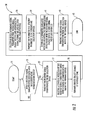
- FIG. 2 is a flowchart illustrating operation of the communication network of FIG. 1 .
- FIG. 3 is a schematic diagram illustrating time slot allocation in one embodiment of the communication network, according to the present invention.
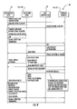
- FIG. 4 is a schematic diagram illustrating a timing sequence between devices in one embodiment of the communication network, according to the present invention.
- FIG. 5 is a chart illustrating a simulation for an embodiment of the communication network, according to the present invention.
- the wireless communication system 10 illustratively includes an other communication network 20, uncooperative to the communication network 16, comprising an uncooperative communications device 21.
- the other communication network 20 may comprise a plurality of uncooperative communications devices.
- the communication networks 20, 16 are unfriendly with each other, i.e., they do not intentionally share communication channels.
- the communication network 16 includes a control device 11, and a plurality of mobile wireless communications devices comprising a plurality of collection devices 12a-12b and a plurality of forward devices 15a-15g.
- the communication network 16 can include a wide variety of differing devices, such as handheld communications devices (e.g., walkie-talkies), vehicle mounted communications devices, and a base station device.
- the forward devices 15a-15g, collection devices 12a-12b, and control device 11 may perform multiple roles.
- the collection devices 12a-12b can also function as a forward device 15a-15g in the communication network 16.
- the control device 11 may also be a collection device 12a-12b and even a forward device 15a-15g.
- the collection/receiver devices can perform the functionality of multiple devices, and they are not limited to a single specific role.
- Each forward device 15a-15g is configured to detect a received signal characteristic associated, i.e., regarding a signal emitted therefrom, with the uncooperative communications device 21 (Block 33).
- the received signal characteristic may comprise one or more of a bandwidth value, an assigned time value, a frequency value, and a received signal strength value.
- the forward device 15a-15g is configured to transmit the received signal characteristic to the collection device 12a (Block 35).
- the forward device 15a-15g may be configured to detect the received signal characteristic by scanning an operative frequency of the respective forward device.
- each forward device 15a-15g comprises a plurality of diversity antennas 19a-19b and is configured to detect the received signal characteristic associated with the uncooperative communications device 21 using the plurality of diversity antennas.
- the forward device 15a-15g scans each operative frequency for all the on-board antennas 19a-19b. Multiple antennas 19a-19b at a forward device 15a-15g could provide additional capability on bearing, amplitude, and other parameters.
- the forward device 15a-15g transmits the data to the collection device 12a in charge of the local subnet in the communication network 16, such as a master node (mobile ad hoc network embodiments) or base station.
- the forward device 15a-15g may be configured to transmit a respective locational value and time value associated with the received signal characteristic to the collection device 12a-12b, i.e., the forward node time/date/location stamps the data.
- the collection device 12a is configured to selectively schedule detection or reception of the received signal characteristic based upon a timing of communications among the plurality of forward devices 15a-15g.
- the collection device 12a is configured to schedule detection of the received signal substantially simultaneously for each of the forward devices 15a-15g, and to transmit the received signal characteristic to the control device 11 (Blocks 37-38).
- the collection devices 12a-12b serve as a backbone of the communication network 16 and route the information to the control device 11 (Block 39).
- the collection devices 12a-12b may each have a direct coupling to the control device 11.
- the collection devices 12a-12b may be configured to coordinate with forward devices 15a-15g in a respective subnet for cooperation with nearby other forward devices to detect the received signal characteristic associated with the uncooperative communications device 21.
- the collection device 12a-12b may offload the detection duties to nearby forward devices 15a-15f.
- the communication network 16 may address this situation with the control device 11 scheduling a coordinated detection in these locations when the forward device 15a-15g is known not to have any scheduled transmissions or reception.
- An alternate approach is to task many forward devices 15a-15g to make the detection. If a forward device 15a-15g is "busy,” then it quietly disregards the command. The collection node 12a-12b can still make the measurement of location, movement, other if enough forward nodes do act on the request.
- the plurality of forward devices 15a-15g may be configured to operate based upon a CSMA protocol, and each forward device may be configured to detect the received signal characteristic during an absence of traffic directed thereto.
- the plurality of forward devices 15a-15g may be configured to operate based upon a TDMA protocol, and the collection device 12a-12b may be configured to assign a time slot for detection of the received signal characteristic associated with the uncooperative communications device 21.
- the forward devices 15a-15g may be configured to operate with a dedicated guard receiver separate from the communications receiver. In addition to a guard receiver, other systems may use multiple antennas.
- the collection device 12a includes a processor 13 and a memory 14 cooperating therewith.
- the processor 13 may be configured to store one or more uncooperative communications device type features in the memory 14 and to correlate the received signal characteristic from the plurality of forward devices 15a-15g with at least one uncooperative communications device type feature.
- the uncooperative communications device type feature may comprise a waveform feature characteristic or a transmission signal signature of some form.
- the control device 11 may store equipment correlations with uncooperative communications device types, thereby determining uncooperative equipment location data.
- the forward device 15a-15g may store uncooperative communications device type features in memory and correlate against them. This may reduce the transmission bandwidth required in getting data/information from the forward nodes to the collection node.
- the forward devices 15a-15g and/or the collections devices 12a-12b may be configured to detect the received signal characteristic by sampling a received signal from the uncooperative communications device 21, and to transmit the sampled received signal data to an upstream collection device or the control device 11. In other words, the heavy processing burdens are shifted up the communication chain to devices that likely have greater resources.
- the collection device 12a-12b may be configured to determine a plurality of received signal characteristics from the data received from the forward devices 15a-15g, such as a time of arrival value, and a Doppler value. In these embodiments, some pre-processing is performed by the collection devices 12a-12b before it is routed to the control device 11. The collection device 12a-12b aggregates the data it receives, and also calculates parameters based on the signals received (Block 36). These parameters can include TDOA, FDOA, amplitude differences, etc. It may also perform location estimation; however, this would typically be done at the control device 11.
- the control device 11 is configured to determine one or more parameters associated with the uncooperative communications device 21 based upon the received signal characteristic received from the collection devices 12a-12b (Block 41).
- the plurality of parameters may comprise a location value, a movement value, a transmission characteristic value, and/or an accompanying equipment parameter.
- control device 11 is configured to determine a strategy parameter associated with the uncooperative communications device 21 and based upon the determined parameter. For example, the control device 11 may determine that associated users of the other communication network 20, i.e., the one or more uncooperative communications devices 21, may be strategically outmaneuvering users in the communication network 16.
- the control device 1 1 is configured to transmit the parameter and the strategy parameter to the plurality of mobile wireless communications devices 15a-15g, 12a-12b (Blocks 43, 45).
- control device 11 can be omitted, and its functionality can be assigned to the most capable collection device 12a-12b.
- the collection devices 12a-12b serve not only as the backbone of the communications network 16 but also the brain.
- the collection devices 12a-12b may arbitrate network time for simultaneous listening, perform signal correlation determination, perform time difference of arrival estimates, perform power difference of arrival estimates, perform frequency difference of arrival estimates, and forward results to next collection point.
- the devices may be configured to listen at an assigned time, frequency, and bandwidth, perform signal detection, perform signal evaluation if assigned, provide a time stamp with global positioning system (GPS), and lastly send results to assigned collection node.
- GPS global positioning system
- control device 11 may be configured to maintain a list of radios, including capability, location, and current search list for each forward device 15a-15g.
- the control device 11 can also be configured to serve as the final processing stage, which includes geolocation estimation, tracking algorithms, and other processing.
- the control device 11 may also be configured to manage results by updating search descriptions, assigning/changing collection points, and pushing results updates back to all nodes.
- the command/control can be an external process or internal to the radio. In versatile applications, the command/control application can exist at any node in the communication network 16.
- the communication network 16 leverages the existing plurality of mobile wireless communications devices 12a-12b, 15a-15g to scout the uncooperative communications device 21.
- the users of the communication network 16 can be informed of hidden uncooperative communications device 21 users via the command/control backbone.
- the communication network 16 may determine location, density of personnel.
- the control device 11 is able to determine the type of device for the uncooperative communications device 21 (particularly when the communications device type can be associated with equipment), the control device can forward this information to nearby users in the communication network 16 for strategic reasons.
- the other communication network 20 comprises an uncooperative communications device 21.
- the communication network 16 comprises a control device 11, and a plurality of mobile wireless communications devices comprising a collection device 12a-12b and a plurality of forward devices 15a-15g.
- the method comprises using each forward device 15a-15g to detect a received signal characteristic associated with the uncooperative communications device 21, and transmit the received signal characteristic to the collection device 12a-12b, and using the collection device to selectively schedule detection of the received signal characteristic based upon a timing of communications among the plurality of forward devices, and to transmit the received signal characteristic to the control device.
- the method also includes using the control device 11 to determine a parameter associated with the uncooperative communications device 21 based upon the received signal characteristic received from the collection device 12a-12b.
- TDMA and CSMA are shown as two examples.
- Typical ad-hoc TDMA systems include a period of network arbitration slots followed by assigned data slots 51-54. Within each data slot, a predetermined radio is allowed to transmit. The pattern of arbitration and data slots is repeated over and over. This fundamental duration is called the epoch duration 50.
- Each radio in the network arbitrates an assigned time slot to transmit. During the other allocated radio transmit slots, each radio will listen to the transmission for data that is addressed to them. The assignment of a data slot is controlled by the MAC layer for the communications waveform. Typically, a single radio in the network acts as the arbitrator master of the time slots.
- a forward node When a forward node receives a request for a communication location aware waveform (CLAW) signal detection, the CLAW application can try to listen on unused slots. This can be done on slots that are assigned to be empty or on slots when a signal is not detected after a brief amount of time. If slots are not open, requests that some number of slots be allocated for it and other nodes to use for a predetermined about of time can be made to the network arbitrator. Once the time has been granted, the assigned radio will listen at the desired frequency, bandwidth, and time as illustrated in FIG. 3 .
- CLAW communication location aware waveform
- this time can be relatively small.
- the time required will increase. If the allotted CLAW time duration is not sufficient for the signals for geolocation, a large number of slots 51-54 can be allocated (up to a complete epoch 50) for a brief period of time. The additional amount of data will need to be compressed prior to collection for correlation.
- each unit sends a request to send (RTS) message to the desired receiving station for point-to-point transmissions.
- RTS request to send
- CTS clear to send
- the transmitting node On receipt of a CTS message, the transmitting node transmits the data package. In some instances, the receiving node responds with a "done" message. If there is traffic on the channel or if the receiving station does not respond, the requesting transmitter goes into a random back off duration before attempting to transmit again.
- the detection durations do not necessarily have to be coordinated. If there is traffic on the channel and it is not intended for the forward node, this node is free to scan other frequencies to detect signals of interest. If a channel is heavily utilized by a particular node, then it must prioritize time for scanning along with RX or TX data. This can be accomplished by not providing a CTS message for a prescribed time or holding off lower priority data packets.
- All forward nodes may need to be receiving at exactly the same time.
- the collection nodes are required to communicate the time and duration to the each of the respective forward nodes under its supervision.
- the CSMA protocols will time out. It is helpful that the collection nodes understand the CSMA protocol such as to efficiently assign time without a large penalty in system throughput due to CSMA back off durations.
- a sequence diagram 60 illustratively includes the application node (control device 11 from hereinabove), the collection node (collection device 12a-12b from hereinabove), and the forward node(s) (forward devices 15a-15g from hereinabove), each are given a separate block.
- a collection node may also be a forward node.
- the application node may be a collection node or forward node as well. These nodes may reside anywhere in a network.
- Simulations were performed for a system looking for a predefined signal pattern. This pattern was stored in the forward nodes.
- the MAC search window was predefined and fixed. Each radio in the network searched for the signal by correlating the received signal to the known preamble. On detecting the preamble, the time of the correlation was determined using a GPS signal. This time was logged. Offline, the times were post processed with only TDOA techniques.
- the target signals were placed at different locations around Rochester, NY. The TDOA measurements were taken at each location. The results are shown in the image 70 of FIG. 5 .
- the circles 15a-15g are the locations of the forward nodes.
- the triangles show the location of the unknown transmitter (uncooperative communications devices 21a-21c).
- Each x-mark 72a-72n represents a single estimate based on a single observation of the unknown transmitter location.
Landscapes
- Engineering & Computer Science (AREA)
- Computer Networks & Wireless Communication (AREA)
- Signal Processing (AREA)
- Physics & Mathematics (AREA)
- General Physics & Mathematics (AREA)
- Radar, Positioning & Navigation (AREA)
- Remote Sensing (AREA)
- Mobile Radio Communication Systems (AREA)
Abstract
Description
- The present invention relates to the field of wireless communications, and, more particularly, to detecting wireless communications devices and related methods.
- In government, municipal, and law enforcement applications, there is sometimes a desire to track a communications device. Since it is not uncommon for a person to carry a cellular telephone device with them on a daily basis, there may be desire by local police and fire departments to use a corresponding cellular telephone device to help locate a missing person, for example, a person trapped in a collapsed building or a fugitive. Of course, in these applications, such as tracking a cellular communications device, the device and associated user are not actively attempting to mask their location, i.e., an uncooperative communications device. Conventional approaches to communications device location include systems comprising a plurality of sensors. These systems typically use a triangulation method to determine the location of the communications device.
- One approach to communications device location, for example, a cellular telephone device, is disclosed by
U.S. Patent No. 6,407,703 to Minter et al. The system of Minter et al. includes a plurality of sensors situated in multiple locations/platforms. The system uses angle of arrival (AOA), time difference of arrival (TDOA), and terrain altitude information from signal intercepts from the cellular telephone device to determine the location thereof. The sensors use accurate time synchronization for determining the TDOA of the intercepted signals. - Another approach is disclosed in
U.S. Patent No. 5,719,584 to Otto , assigned to the present application's assignee, Harris Corporation of Melbourne, FL. This system uses a plurality of ground based sensors to determine a location of the cellular telephone device by measuring TDOA and AOA values. This network of sensors is also synchronized. - Another approach is disclosed in
U.S. Patent Application Publication No. 2004/0135717 to Gounalis . Gounalis discloses a system for detecting wireless transmission signals from an emitter. The system determines and implements a selective scanning strategy, for example, using a frequency domain windowing approach. - Another approach is disclosed in
U.S. Patent No. 7,944,468 to Hoffman et al. Hoffman et al. discloses a predictive threat detection system. The system includes a sensor network spread over an urban environment, and combines data for analysis from each of these sites. A potential drawback to the above systems is that no approach provides a method for distributing information to cooperative communications devices. Moreover, deploying a large network of sensors, such as in Hoffman et al., can be expensive and impractical. - In view of the foregoing background, it is therefore an object of the present invention to provide a communication network that can efficiently track uncooperative communications devices.
- This and other objects, features, and advantages in accordance with the present invention are provided by a communication network uncooperative with an uncooperative communications device, the communication network comprising a plurality of mobile wireless communications devices comprising at least one collection device and a plurality of forward devices. Each forward device is configured to detect a received signal characteristic associated with the uncooperative communications device, and transmit the received signal characteristic to the at least one collection device. The at least one collection device is configured to selectively schedule reception of the received signal characteristic based upon a timing of communications among the plurality of forward devices, and to determine a parameter associated with the uncooperative communications device based upon the received signal characteristic. Advantageously, the communication network leverages the existing plurality of mobile wireless communications devices to scout the uncooperative communications device.
- In some embodiments, the communication network may further comprise a control device, and the at least one collection device may be configured to transmit the received signal characteristic to the control device. The control device may be configured to cooperate with the at least one collection device to determine the parameter associated with the uncooperative communications device based upon the received signal characteristic received from the at least one collection device.
- More specifically, the control device may be configured to determine a plurality of parameters associated with the uncooperative communications device based upon the received signal characteristic received from the at least one collection device, the plurality of parameters comprising a location value, a movement value, and a transmission characteristic value, for example. Each forward device may be configured to transmit a respective locational value and time value associated with the received signal characteristic to the at least one collection device. In some embodiments, each forward device may comprise a plurality of diversity antennas and may be configured to detect the received signal characteristic associated with the uncooperative communications device using the plurality of diversity antennas.
- Another aspect is directed to a method of operating a communication network uncooperative with an uncooperative communications device. The communication network comprises a plurality of mobile wireless communications devices comprising at least one collection device and a plurality of forward devices. The method comprises using each forward device to detect a received signal characteristic associated with the uncooperative communications device, and transmit the received signal characteristic to the at least one collection device. The method also includes using the at least one collection device to selectively schedule reception of the received signal characteristic based upon a timing of communications among the plurality of forward devices, and to determine a parameter associated with the uncooperative communications device based upon the received signal characteristic received from the at least one collection device.
-
FIG. 1 is a schematic diagram of a communication network, according to the present invention. -
FIG. 2 is a flowchart illustrating operation of the communication network ofFIG. 1 . -
FIG. 3 is a schematic diagram illustrating time slot allocation in one embodiment of the communication network, according to the present invention. -
FIG. 4 is a schematic diagram illustrating a timing sequence between devices in one embodiment of the communication network, according to the present invention. -
FIG. 5 is a chart illustrating a simulation for an embodiment of the communication network, according to the present invention. - The present invention will now be described more fully hereinafter with reference to the accompanying drawings, in which preferred embodiments of the invention are shown. This invention may, however, be embodied in many different forms and should not be construed as limited to the embodiments set forth herein. Rather, these embodiments are provided so that this disclosure will be thorough and complete, and will fully convey the scope of the invention to those skilled in the art. Like numbers refer to like elements throughout.
- Referring initially to
FIGS. 1-2 , awireless communication system 10 comprising acommunication network 16 according to the present invention is now described. Also, with reference to aflowchart 30, which begins atBlock 31, a method of operating thecommunication network 16 is also described. Thewireless communication system 10 illustratively includes another communication network 20, uncooperative to thecommunication network 16, comprising anuncooperative communications device 21. Of course, theother communication network 20 may comprise a plurality of uncooperative communications devices. In other words, thecommunication networks - The
communication network 16 includes acontrol device 11, and a plurality of mobile wireless communications devices comprising a plurality ofcollection devices 12a-12b and a plurality offorward devices 15a-15g. For ease of illustration, only oneforward device 15a and onecollection device 12a are shown in detail. Of course, the other companion devices may be similarly constituted. Thecommunication network 16 can include a wide variety of differing devices, such as handheld communications devices (e.g., walkie-talkies), vehicle mounted communications devices, and a base station device. Theforward devices 15a-15g,collection devices 12a-12b, andcontrol device 11 may perform multiple roles. For example, thecollection devices 12a-12b can also function as aforward device 15a-15g in thecommunication network 16. In some embodiments, thecontrol device 11 may also be acollection device 12a-12b and even aforward device 15a-15g. In other words, the collection/receiver devices can perform the functionality of multiple devices, and they are not limited to a single specific role. - Each
forward device 15a-15g is configured to detect a received signal characteristic associated, i.e., regarding a signal emitted therefrom, with the uncooperative communications device 21 (Block 33). For example, the received signal characteristic may comprise one or more of a bandwidth value, an assigned time value, a frequency value, and a received signal strength value. - Once a received signal characteristic is detected, the
forward device 15a-15g is configured to transmit the received signal characteristic to thecollection device 12a (Block 35). In some embodiments, theforward device 15a-15g may be configured to detect the received signal characteristic by scanning an operative frequency of the respective forward device. In the illustrated embodiment, eachforward device 15a-15g comprises a plurality ofdiversity antennas 19a-19b and is configured to detect the received signal characteristic associated with theuncooperative communications device 21 using the plurality of diversity antennas. Theforward device 15a-15g scans each operative frequency for all the on-board antennas 19a-19b.Multiple antennas 19a-19b at aforward device 15a-15g could provide additional capability on bearing, amplitude, and other parameters. - Typically, the
forward device 15a-15g transmits the data to thecollection device 12a in charge of the local subnet in thecommunication network 16, such as a master node (mobile ad hoc network embodiments) or base station. In some embodiments, theforward device 15a-15g may be configured to transmit a respective locational value and time value associated with the received signal characteristic to thecollection device 12a-12b, i.e., the forward node time/date/location stamps the data. - As such, the
collection device 12a is configured to selectively schedule detection or reception of the received signal characteristic based upon a timing of communications among the plurality offorward devices 15a-15g. Thecollection device 12a is configured to schedule detection of the received signal substantially simultaneously for each of theforward devices 15a-15g, and to transmit the received signal characteristic to the control device 11 (Blocks 37-38). In the illustrated embodiment, thecollection devices 12a-12b serve as a backbone of thecommunication network 16 and route the information to the control device 11 (Block 39). In other embodiments, thecollection devices 12a-12b may each have a direct coupling to thecontrol device 11. Thecollection devices 12a-12b may be configured to coordinate withforward devices 15a-15g in a respective subnet for cooperation with nearby other forward devices to detect the received signal characteristic associated with theuncooperative communications device 21. - For example, if a particular
forward device 15a-15g cannot perform detection processes due to significant communication demands by the respective user (e.g., reduced receive sensitivity due to ongoing transmissions), thecollection device 12a-12b may offload the detection duties tonearby forward devices 15a-15f. Thecommunication network 16 may address this situation with thecontrol device 11 scheduling a coordinated detection in these locations when theforward device 15a-15g is known not to have any scheduled transmissions or reception. An alternate approach is to task manyforward devices 15a-15g to make the detection. If aforward device 15a-15g is "busy," then it quietly disregards the command. Thecollection node 12a-12b can still make the measurement of location, movement, other if enough forward nodes do act on the request. - In some embodiments, the plurality of
forward devices 15a-15g may be configured to operate based upon a CSMA protocol, and each forward device may be configured to detect the received signal characteristic during an absence of traffic directed thereto. In different embodiments (FIG. 3 ), the plurality offorward devices 15a-15g may be configured to operate based upon a TDMA protocol, and thecollection device 12a-12b may be configured to assign a time slot for detection of the received signal characteristic associated with theuncooperative communications device 21. In other embodiments, theforward devices 15a-15g may be configured to operate with a dedicated guard receiver separate from the communications receiver. In addition to a guard receiver, other systems may use multiple antennas. - In the illustrated embodiment, the
collection device 12a includes aprocessor 13 and amemory 14 cooperating therewith. Theprocessor 13 may be configured to store one or more uncooperative communications device type features in thememory 14 and to correlate the received signal characteristic from the plurality offorward devices 15a-15g with at least one uncooperative communications device type feature. For example, the uncooperative communications device type feature may comprise a waveform feature characteristic or a transmission signal signature of some form. Advantageously, thecontrol device 11 may store equipment correlations with uncooperative communications device types, thereby determining uncooperative equipment location data. Also advantageously, theforward device 15a-15g may store uncooperative communications device type features in memory and correlate against them. This may reduce the transmission bandwidth required in getting data/information from the forward nodes to the collection node. - In other embodiments, the
forward devices 15a-15g and/or thecollections devices 12a-12b may be configured to detect the received signal characteristic by sampling a received signal from theuncooperative communications device 21, and to transmit the sampled received signal data to an upstream collection device or thecontrol device 11. In other words, the heavy processing burdens are shifted up the communication chain to devices that likely have greater resources. - In certain embodiments, the
collection device 12a-12b may be configured to determine a plurality of received signal characteristics from the data received from theforward devices 15a-15g, such as a time of arrival value, and a Doppler value. In these embodiments, some pre-processing is performed by thecollection devices 12a-12b before it is routed to thecontrol device 11. Thecollection device 12a-12b aggregates the data it receives, and also calculates parameters based on the signals received (Block 36). These parameters can include TDOA, FDOA, amplitude differences, etc. It may also perform location estimation; however, this would typically be done at thecontrol device 11. - The
control device 11 is configured to determine one or more parameters associated with theuncooperative communications device 21 based upon the received signal characteristic received from thecollection devices 12a-12b (Block 41). For example, the plurality of parameters may comprise a location value, a movement value, a transmission characteristic value, and/or an accompanying equipment parameter. - Additionally, the
control device 11 is configured to determine a strategy parameter associated with theuncooperative communications device 21 and based upon the determined parameter. For example, thecontrol device 11 may determine that associated users of theother communication network 20, i.e., the one or moreuncooperative communications devices 21, may be strategically outmaneuvering users in thecommunication network 16. Thecontrol device 11 is configured to transmit the parameter and the strategy parameter to the plurality of mobilewireless communications devices 15a-15g, 12a-12b (Blocks 43, 45). - In some embodiments, the
control device 11 can be omitted, and its functionality can be assigned to the mostcapable collection device 12a-12b. In these embodiments, thecollection devices 12a-12b serve not only as the backbone of thecommunications network 16 but also the brain. - In some embodiments, the
collection devices 12a-12b may arbitrate network time for simultaneous listening, perform signal correlation determination, perform time difference of arrival estimates, perform power difference of arrival estimates, perform frequency difference of arrival estimates, and forward results to next collection point. For theforward devices 15a-15g, in some embodiments, the devices may be configured to listen at an assigned time, frequency, and bandwidth, perform signal detection, perform signal evaluation if assigned, provide a time stamp with global positioning system (GPS), and lastly send results to assigned collection node. - In some embodiments, the
control device 11 may be configured to maintain a list of radios, including capability, location, and current search list for eachforward device 15a-15g. Thecontrol device 11 can also be configured to serve as the final processing stage, which includes geolocation estimation, tracking algorithms, and other processing. Thecontrol device 11 may also be configured to manage results by updating search descriptions, assigning/changing collection points, and pushing results updates back to all nodes. In some embodiments, the command/control can be an external process or internal to the radio. In versatile applications, the command/control application can exist at any node in thecommunication network 16. - Advantageously, the
communication network 16 leverages the existing plurality of mobilewireless communications devices 12a-12b, 15a-15g to scout theuncooperative communications device 21. For example, the users of thecommunication network 16 can be informed of hiddenuncooperative communications device 21 users via the command/control backbone. Thecommunication network 16 may determine location, density of personnel. Also, if thecontrol device 11 is able to determine the type of device for the uncooperative communications device 21 (particularly when the communications device type can be associated with equipment), the control device can forward this information to nearby users in thecommunication network 16 for strategic reasons. - Another aspect is directed to a method of operating a
communication network 16 uncooperative with another communication network 20. Theother communication network 20 comprises anuncooperative communications device 21. Thecommunication network 16 comprises acontrol device 11, and a plurality of mobile wireless communications devices comprising acollection device 12a-12b and a plurality offorward devices 15a-15g. The method comprises using eachforward device 15a-15g to detect a received signal characteristic associated with theuncooperative communications device 21, and transmit the received signal characteristic to thecollection device 12a-12b, and using the collection device to selectively schedule detection of the received signal characteristic based upon a timing of communications among the plurality of forward devices, and to transmit the received signal characteristic to the control device. The method also includes using thecontrol device 11 to determine a parameter associated with theuncooperative communications device 21 based upon the received signal characteristic received from thecollection device 12a-12b. - Referring to
FIG. 3 , as will be appreciated by those skilled in the art, an exemplary implementation of thewireless communication system 10 is illustrated. There are many different kinds of network protocols. A brief description of TDMA and CSMA are shown as two examples. - Typical ad-hoc TDMA systems include a period of network arbitration slots followed by assigned data slots 51-54. Within each data slot, a predetermined radio is allowed to transmit. The pattern of arbitration and data slots is repeated over and over. This fundamental duration is called the
epoch duration 50. - Each radio in the network arbitrates an assigned time slot to transmit. During the other allocated radio transmit slots, each radio will listen to the transmission for data that is addressed to them. The assignment of a data slot is controlled by the MAC layer for the communications waveform. Typically, a single radio in the network acts as the arbitrator master of the time slots.
- When a forward node receives a request for a communication location aware waveform (CLAW) signal detection, the CLAW application can try to listen on unused slots. This can be done on slots that are assigned to be empty or on slots when a signal is not detected after a brief amount of time. If slots are not open, requests that some number of slots be allocated for it and other nodes to use for a predetermined about of time can be made to the network arbitrator. Once the time has been granted, the assigned radio will listen at the desired frequency, bandwidth, and time as illustrated in
FIG. 3 . - For signal detection, this time can be relatively small. For signal geolocation, the time required will increase. If the allotted CLAW time duration is not sufficient for the signals for geolocation, a large number of slots 51-54 can be allocated (up to a complete epoch 50) for a brief period of time. The additional amount of data will need to be compressed prior to collection for correlation.
- In the CSMA architecture, each unit sends a request to send (RTS) message to the desired receiving station for point-to-point transmissions. The receiving station acknowledges the RTS message with a clear to send (CTS) message. On receipt of a CTS message, the transmitting node transmits the data package. In some instances, the receiving node responds with a "done" message. If there is traffic on the channel or if the receiving station does not respond, the requesting transmitter goes into a random back off duration before attempting to transmit again.
- For the CSMA protocol, the detection durations do not necessarily have to be coordinated. If there is traffic on the channel and it is not intended for the forward node, this node is free to scan other frequencies to detect signals of interest. If a channel is heavily utilized by a particular node, then it must prioritize time for scanning along with RX or TX data. This can be accomplished by not providing a CTS message for a prescribed time or holding off lower priority data packets.
- However, the time and signal for geolocation will have to be coordinated. All forward nodes may need to be receiving at exactly the same time. The collection nodes are required to communicate the time and duration to the each of the respective forward nodes under its supervision.
- If another radio tries to communicate with a radio that is servicing a CLAW search, the CSMA protocols will time out. It is helpful that the collection nodes understand the CSMA protocol such as to efficiently assign time without a large penalty in system throughput due to CSMA back off durations.
- Referring now to
FIG. 4 , a sequence diagram 60 illustratively includes the application node (control device 11 from hereinabove), the collection node (collection device 12a-12b from hereinabove), and the forward node(s) (forward devices 15a-15g from hereinabove), each are given a separate block. There can be many forward nodes in the configuration, and some nodes can perform multiple roles. For example, a collection node may also be a forward node. The application node may be a collection node or forward node as well. These nodes may reside anywhere in a network. - Simulations were performed for a system looking for a predefined signal pattern. This pattern was stored in the forward nodes. The MAC search window was predefined and fixed. Each radio in the network searched for the signal by correlating the received signal to the known preamble. On detecting the preamble, the time of the correlation was determined using a GPS signal. This time was logged. Offline, the times were post processed with only TDOA techniques. The target signals were placed at different locations around Rochester, NY. The TDOA measurements were taken at each location. The results are shown in the image 70 of
FIG. 5 . Thecircles 15a-15g are the locations of the forward nodes. The triangles show the location of the unknown transmitter (uncooperative communications devices 21a-21c). Each x-mark 72a-72n represents a single estimate based on a single observation of the unknown transmitter location.
Claims (10)
- A communication network uncooperative with an uncooperative communications device, the communication network comprising:a plurality of mobile wireless communications devices comprising at least one collection device and a plurality of forward devices, each forward device configured to
detect a received signal characteristic associated with the uncooperative communications device, and
transmit the received signal characteristic to said at least one collection device;said at least one collection device configured to
selectively schedule reception of the received signal characteristic based upon a timing of communications among said plurality of forward devices, and
determine a parameter associated with the uncooperative communications device based upon the received signal characteristic received from said at least one collection device. - The communication network of claim 1 further comprising a control device; wherein said at least one collection device is configured to transmit the received signal characteristic to said control device; and wherein said control device is configured to cooperate with said at least one collection device to determine the parameter associated with the uncooperative communications device based upon the received signal characteristic received from said at least one collection device.
- The communication network of claim 1 wherein the parameter comprises at least one of a location value, a movement value, and a transmission characteristic value.
- The communication network of claim 1 wherein each forward device is configured to transmit a respective locational value and time value associated with the received signal characteristic to said at least one collection device.
- The communication network of claim 1 wherein each forward device is configured to detect the received signal characteristic by scanning an operative frequency of the respective forward device.
- The communication network of claim 1 wherein said at least one collection device comprises a processor and a memory cooperating therewith; and wherein said processor is configured to store an uncooperative communications device type feature in said memory and to correlate the received signal characteristic from said plurality of forward devices with the uncooperative communications device type feature.
- The communication network of claim 1 wherein each forward device is configured to detect the received signal characteristic by sampling a received signal from the uncooperative communications device, and to transmit the sampled received signal data to said at least one collection device.
- A method of operating a communication network uncooperative with an uncooperative communications device, the communication network comprising a plurality of mobile wireless communications devices comprising at least one collection device, and a plurality of forward devices, the method comprising:detecting, using each forward device, a received signal characteristic associated with the uncooperative communications device, and transmitting the received signal characteristic to the at least one collection device;selectively scheduling, using the at least one collection device, reception of the received signal characteristic based upon a timing of communications among the plurality of forward devices; anddetermining, using the at least one collection device, a parameter associated with the uncooperative communications device based upon the received signal characteristic.
- The method of claim 8 wherein the communication network further comprises a control device; further comprising:transmitting, using the at least one collection device, the received signal characteristic to the control device; andthe control device and the at least one collection device cooperating with each other to determine the parameter associated with the uncooperative communications device based upon the received signal characteristic received from the at least one collection device.
- The method of claim 8 wherein the parameter comprises at least one of a location value, a movement value, and a transmission characteristic value.
Applications Claiming Priority (1)
| Application Number | Priority Date | Filing Date | Title |
|---|---|---|---|
| US13/407,964 US8792464B2 (en) | 2012-02-29 | 2012-02-29 | Communication network for detecting uncooperative communications device and related methods |
Publications (2)
| Publication Number | Publication Date |
|---|---|
| EP2635079A1 true EP2635079A1 (en) | 2013-09-04 |
| EP2635079B1 EP2635079B1 (en) | 2018-04-11 |
Family
ID=47738987
Family Applications (1)
| Application Number | Title | Priority Date | Filing Date |
|---|---|---|---|
| EP13000756.0A Active EP2635079B1 (en) | 2012-02-29 | 2013-02-14 | Communication network for tracking a communications device |
Country Status (3)
| Country | Link |
|---|---|
| US (1) | US8792464B2 (en) |
| EP (1) | EP2635079B1 (en) |
| IL (1) | IL224708A0 (en) |
Families Citing this family (3)
| Publication number | Priority date | Publication date | Assignee | Title |
|---|---|---|---|---|
| KR101931601B1 (en) | 2011-11-17 | 2019-03-13 | 삼성전자주식회사 | Method and apparatus for handling security key to authenticate with a mobile station in a radio communication system |
| KR101964142B1 (en) * | 2012-10-25 | 2019-08-07 | 삼성전자주식회사 | Method and apparatus for handling security key of a mobile station for cooperating with multiple base stations in a radio communication system |
| US20150222508A1 (en) * | 2013-09-23 | 2015-08-06 | Empire Technology Development, Llc | Ubiquitous computing (ubicomp) service detection by network tomography |
Citations (6)
| Publication number | Priority date | Publication date | Assignee | Title |
|---|---|---|---|---|
| US5719584A (en) | 1996-09-03 | 1998-02-17 | Harris Corporation | System and method for determining the geolocation of a transmitter |
| US6407703B1 (en) | 2000-08-07 | 2002-06-18 | Lockheed Martin Corporation | Multi-platform geolocation method and system |
| US20040135717A1 (en) | 2002-11-18 | 2004-07-15 | Lockheed Martin Corporation | System and method for detecting emitters signals having multi-valued illumination times |
| WO2010063469A1 (en) * | 2008-12-04 | 2010-06-10 | Alcatel Lucent | Providing location information |
| US20100273504A1 (en) * | 2009-04-22 | 2010-10-28 | Trueposition, Inc. | Network Autonomous Wireless Location System |
| US7944468B2 (en) | 2005-07-05 | 2011-05-17 | Northrop Grumman Systems Corporation | Automated asymmetric threat detection using backward tracking and behavioral analysis |
Family Cites Families (16)
| Publication number | Priority date | Publication date | Assignee | Title |
|---|---|---|---|---|
| US5451956A (en) | 1993-08-20 | 1995-09-19 | Trw Inc. | Instantaneous parameter measuring receiver |
| US20100030423A1 (en) * | 1999-06-17 | 2010-02-04 | Paxgrid Telemetric Systems, Inc. | Automotive telemetry protocol |
| US6166679A (en) | 1999-01-13 | 2000-12-26 | Lemelson Jerome H. | Friend or foe detection system and method and expert system military action advisory system and method |
| US7475428B2 (en) | 2002-06-20 | 2009-01-06 | Angel Secure Networks, Inc. | Secure detection network system |
| US7158501B2 (en) * | 2001-05-29 | 2007-01-02 | Kabushiki Kaisha Toshiba | Wireless communication apparatus |
| US7298314B2 (en) * | 2002-08-19 | 2007-11-20 | Q-Track Corporation | Near field electromagnetic positioning system and method |
| US7068209B2 (en) | 2002-11-18 | 2006-06-27 | Lockheed Martin Corporation | System and method for detecting and jamming emitter signals |
| US20050105505A1 (en) * | 2003-11-07 | 2005-05-19 | Eran Fishler | Transceiver for a wireless local area network having a sparse preamble data sequence |
| US8019352B2 (en) * | 2004-07-23 | 2011-09-13 | Wireless Valley Communications, Inc. | System, method, and apparatus for determining and using the position of wireless devices or infrastructure for wireless network enhancements |
| KR100681260B1 (en) * | 2004-10-07 | 2007-02-09 | 삼성전자주식회사 | Speed Matched Channel Estimation Method Using Power Spectrum Based Speed Estimation and Demodulator of Mobile Communication Terminal Using the Same |
| KR100913872B1 (en) * | 2006-01-18 | 2009-08-26 | 삼성전자주식회사 | Device for transmitting and receiving data in communication system |
| US20080144572A1 (en) * | 2006-12-15 | 2008-06-19 | Makhijani Mahesh A | Method and Apparatus for Achieving Frequency Diversity in Scheduled Packet Data Transmissions |
| US8457498B2 (en) | 2007-07-20 | 2013-06-04 | At&T Intellectual Property I, L.P. | Methods and apparatus for target identification |
| EP2449804A4 (en) * | 2009-06-30 | 2016-11-30 | Nokia Technologies Oy | Apparatus, method, computer program for communication and system thereof |
| US8259652B2 (en) * | 2009-11-17 | 2012-09-04 | Apple Inc. | Location-based network detection |
| US8917663B2 (en) * | 2010-11-29 | 2014-12-23 | Spidercloud Wireless, Inc. | Method and apparatus for timing and/or frequency offset monitoring and handling |
-
2012
- 2012-02-29 US US13/407,964 patent/US8792464B2/en active Active
-
2013
- 2013-02-14 EP EP13000756.0A patent/EP2635079B1/en active Active
- 2013-02-14 IL IL224708A patent/IL224708A0/en active IP Right Grant
Patent Citations (6)
| Publication number | Priority date | Publication date | Assignee | Title |
|---|---|---|---|---|
| US5719584A (en) | 1996-09-03 | 1998-02-17 | Harris Corporation | System and method for determining the geolocation of a transmitter |
| US6407703B1 (en) | 2000-08-07 | 2002-06-18 | Lockheed Martin Corporation | Multi-platform geolocation method and system |
| US20040135717A1 (en) | 2002-11-18 | 2004-07-15 | Lockheed Martin Corporation | System and method for detecting emitters signals having multi-valued illumination times |
| US7944468B2 (en) | 2005-07-05 | 2011-05-17 | Northrop Grumman Systems Corporation | Automated asymmetric threat detection using backward tracking and behavioral analysis |
| WO2010063469A1 (en) * | 2008-12-04 | 2010-06-10 | Alcatel Lucent | Providing location information |
| US20100273504A1 (en) * | 2009-04-22 | 2010-10-28 | Trueposition, Inc. | Network Autonomous Wireless Location System |
Non-Patent Citations (1)
| Title |
|---|
| "3rd Generation Partnership Project; Technical Specification Group Radio Access Network; Stage 2 functional specification of User Equipment (UE) positioning in UTRAN (Release 10)", 3GPP STANDARD; 3GPP TS 25.305, 3RD GENERATION PARTNERSHIP PROJECT (3GPP), MOBILE COMPETENCE CENTRE ; 650, ROUTE DES LUCIOLES ; F-06921 SOPHIA-ANTIPOLIS CEDEX ; FRANCE, no. V10.0.0, 7 October 2010 (2010-10-07), pages 1 - 80, XP050461874 * |
Also Published As
| Publication number | Publication date |
|---|---|
| US8792464B2 (en) | 2014-07-29 |
| IL224708A0 (en) | 2016-09-29 |
| EP2635079B1 (en) | 2018-04-11 |
| US20130223417A1 (en) | 2013-08-29 |
Similar Documents
| Publication | Publication Date | Title |
|---|---|---|
| US12442883B2 (en) | Method for performing relative positioning by terminal in wireless communication system supporting sidelink, and apparatus therefor | |
| EP4391602A1 (en) | Method and apparatus for establishing sensing channel, communication device, storage medium and system | |
| US10257832B2 (en) | Method and apparatus for directed adaptive control of dynamic channel selection in wireless networks | |
| US10368247B2 (en) | Cloud DFS super master detector location systems and methods | |
| US9699786B2 (en) | Method and apparatus for integrating radio agent data in network organization of dynamic channel selection in wireless networks | |
| EP3391672B1 (en) | Methods and devices for finding rfid tags | |
| US9622089B1 (en) | Cloud DFS super master systems and methods | |
| Ramli et al. | Hybrid mac protocol for uav-assisted data gathering in a wireless sensor network | |
| US10104665B2 (en) | Method and apparatus for providing dynamic frequency selection spectrum access in peer-to-peer wireless networks | |
| US20070041352A1 (en) | Elevator calling mechanism and method | |
| WO2023164587A1 (en) | Cloud-centric design for hybrid new radio (nr) and ultra-wideband (uwb) positioning | |
| JP5566225B2 (en) | Communication device | |
| EP3855202A1 (en) | Time-of-flight based unified positioning system and methods | |
| CN111220946A (en) | Multi-moving-target positioning error elimination method based on improved extended Kalman filtering | |
| EP2291047B1 (en) | Mobile Communication Apparatus, Communication Method, and Communication System | |
| EP4487582A1 (en) | Cloud-centric design for ultra-wideband (uwb) infrastructure-based positioning | |
| US20170188300A1 (en) | System, method and apparatus for sharing access data for FTM responders | |
| CN105324950A (en) | Cooperative spectrum sensing method and in-vehicle wireless communication device | |
| CN105594151A (en) | Hidden node interference reduction | |
| CN121002922A (en) | A sensing method and device | |
| US8792464B2 (en) | Communication network for detecting uncooperative communications device and related methods | |
| KR101118267B1 (en) | System and method for estimating the location of tags based on UWB | |
| CN119769067A (en) | Method, system and apparatus for collaborative sensing | |
| KR101783807B1 (en) | A location method and a location system for acceptable a plurality of uwb tags | |
| CN118696580A (en) | Cloud-centric design for hybrid New Radio (NR) and ultra-wideband (UWB) positioning |
Legal Events
| Date | Code | Title | Description |
|---|---|---|---|
| PUAI | Public reference made under article 153(3) epc to a published international application that has entered the european phase |
Free format text: ORIGINAL CODE: 0009012 |
|
| 17P | Request for examination filed |
Effective date: 20130214 |
|
| AK | Designated contracting states |
Kind code of ref document: A1 Designated state(s): AL AT BE BG CH CY CZ DE DK EE ES FI FR GB GR HR HU IE IS IT LI LT LU LV MC MK MT NL NO PL PT RO RS SE SI SK SM TR |
|
| AX | Request for extension of the european patent |
Extension state: BA ME |
|
| 17Q | First examination report despatched |
Effective date: 20160530 |
|
| STAA | Information on the status of an ep patent application or granted ep patent |
Free format text: STATUS: EXAMINATION IS IN PROGRESS |
|
| RIC1 | Information provided on ipc code assigned before grant |
Ipc: G01S 5/06 20060101ALN20170922BHEP Ipc: H04W 88/04 20090101ALN20170922BHEP Ipc: G01S 5/02 20100101ALN20170922BHEP Ipc: H04W 64/00 20090101AFI20170922BHEP |
|
| GRAP | Despatch of communication of intention to grant a patent |
Free format text: ORIGINAL CODE: EPIDOSNIGR1 |
|
| STAA | Information on the status of an ep patent application or granted ep patent |
Free format text: STATUS: GRANT OF PATENT IS INTENDED |
|
| RIC1 | Information provided on ipc code assigned before grant |
Ipc: G01S 5/02 20100101ALN20171024BHEP Ipc: H04W 88/04 20090101ALN20171024BHEP Ipc: H04W 64/00 20090101AFI20171024BHEP Ipc: G01S 5/06 20060101ALN20171024BHEP |
|
| INTG | Intention to grant announced |
Effective date: 20171107 |
|
| GRAS | Grant fee paid |
Free format text: ORIGINAL CODE: EPIDOSNIGR3 |
|
| GRAA | (expected) grant |
Free format text: ORIGINAL CODE: 0009210 |
|
| STAA | Information on the status of an ep patent application or granted ep patent |
Free format text: STATUS: THE PATENT HAS BEEN GRANTED |
|
| AK | Designated contracting states |
Kind code of ref document: B1 Designated state(s): AL AT BE BG CH CY CZ DE DK EE ES FI FR GB GR HR HU IE IS IT LI LT LU LV MC MK MT NL NO PL PT RO RS SE SI SK SM TR |
|
| REG | Reference to a national code |
Ref country code: GB Ref legal event code: FG4D |
|
| REG | Reference to a national code |
Ref country code: CH Ref legal event code: EP |
|
| REG | Reference to a national code |
Ref country code: AT Ref legal event code: REF Ref document number: 989316 Country of ref document: AT Kind code of ref document: T Effective date: 20180415 |
|
| REG | Reference to a national code |
Ref country code: IE Ref legal event code: FG4D |
|
| REG | Reference to a national code |
Ref country code: DE Ref legal event code: R096 Ref document number: 602013035600 Country of ref document: DE |
|
| REG | Reference to a national code |
Ref country code: NL Ref legal event code: MP Effective date: 20180411 |
|
| REG | Reference to a national code |
Ref country code: LT Ref legal event code: MG4D |
|
| PG25 | Lapsed in a contracting state [announced via postgrant information from national office to epo] |
Ref country code: NL Free format text: LAPSE BECAUSE OF FAILURE TO SUBMIT A TRANSLATION OF THE DESCRIPTION OR TO PAY THE FEE WITHIN THE PRESCRIBED TIME-LIMIT Effective date: 20180411 |
|
| PG25 | Lapsed in a contracting state [announced via postgrant information from national office to epo] |
Ref country code: AL Free format text: LAPSE BECAUSE OF FAILURE TO SUBMIT A TRANSLATION OF THE DESCRIPTION OR TO PAY THE FEE WITHIN THE PRESCRIBED TIME-LIMIT Effective date: 20180411 Ref country code: ES Free format text: LAPSE BECAUSE OF FAILURE TO SUBMIT A TRANSLATION OF THE DESCRIPTION OR TO PAY THE FEE WITHIN THE PRESCRIBED TIME-LIMIT Effective date: 20180411 Ref country code: NO Free format text: LAPSE BECAUSE OF FAILURE TO SUBMIT A TRANSLATION OF THE DESCRIPTION OR TO PAY THE FEE WITHIN THE PRESCRIBED TIME-LIMIT Effective date: 20180711 Ref country code: BG Free format text: LAPSE BECAUSE OF FAILURE TO SUBMIT A TRANSLATION OF THE DESCRIPTION OR TO PAY THE FEE WITHIN THE PRESCRIBED TIME-LIMIT Effective date: 20180711 Ref country code: FI Free format text: LAPSE BECAUSE OF FAILURE TO SUBMIT A TRANSLATION OF THE DESCRIPTION OR TO PAY THE FEE WITHIN THE PRESCRIBED TIME-LIMIT Effective date: 20180411 Ref country code: LT Free format text: LAPSE BECAUSE OF FAILURE TO SUBMIT A TRANSLATION OF THE DESCRIPTION OR TO PAY THE FEE WITHIN THE PRESCRIBED TIME-LIMIT Effective date: 20180411 Ref country code: PL Free format text: LAPSE BECAUSE OF FAILURE TO SUBMIT A TRANSLATION OF THE DESCRIPTION OR TO PAY THE FEE WITHIN THE PRESCRIBED TIME-LIMIT Effective date: 20180411 Ref country code: SE Free format text: LAPSE BECAUSE OF FAILURE TO SUBMIT A TRANSLATION OF THE DESCRIPTION OR TO PAY THE FEE WITHIN THE PRESCRIBED TIME-LIMIT Effective date: 20180411 |
|
| PG25 | Lapsed in a contracting state [announced via postgrant information from national office to epo] |
Ref country code: HR Free format text: LAPSE BECAUSE OF FAILURE TO SUBMIT A TRANSLATION OF THE DESCRIPTION OR TO PAY THE FEE WITHIN THE PRESCRIBED TIME-LIMIT Effective date: 20180411 Ref country code: GR Free format text: LAPSE BECAUSE OF FAILURE TO SUBMIT A TRANSLATION OF THE DESCRIPTION OR TO PAY THE FEE WITHIN THE PRESCRIBED TIME-LIMIT Effective date: 20180712 Ref country code: LV Free format text: LAPSE BECAUSE OF FAILURE TO SUBMIT A TRANSLATION OF THE DESCRIPTION OR TO PAY THE FEE WITHIN THE PRESCRIBED TIME-LIMIT Effective date: 20180411 Ref country code: RS Free format text: LAPSE BECAUSE OF FAILURE TO SUBMIT A TRANSLATION OF THE DESCRIPTION OR TO PAY THE FEE WITHIN THE PRESCRIBED TIME-LIMIT Effective date: 20180411 |
|
| REG | Reference to a national code |
Ref country code: AT Ref legal event code: MK05 Ref document number: 989316 Country of ref document: AT Kind code of ref document: T Effective date: 20180411 |
|
| PG25 | Lapsed in a contracting state [announced via postgrant information from national office to epo] |
Ref country code: PT Free format text: LAPSE BECAUSE OF FAILURE TO SUBMIT A TRANSLATION OF THE DESCRIPTION OR TO PAY THE FEE WITHIN THE PRESCRIBED TIME-LIMIT Effective date: 20180813 |
|
| REG | Reference to a national code |
Ref country code: DE Ref legal event code: R097 Ref document number: 602013035600 Country of ref document: DE |
|
| PG25 | Lapsed in a contracting state [announced via postgrant information from national office to epo] |
Ref country code: CZ Free format text: LAPSE BECAUSE OF FAILURE TO SUBMIT A TRANSLATION OF THE DESCRIPTION OR TO PAY THE FEE WITHIN THE PRESCRIBED TIME-LIMIT Effective date: 20180411 Ref country code: RO Free format text: LAPSE BECAUSE OF FAILURE TO SUBMIT A TRANSLATION OF THE DESCRIPTION OR TO PAY THE FEE WITHIN THE PRESCRIBED TIME-LIMIT Effective date: 20180411 Ref country code: SK Free format text: LAPSE BECAUSE OF FAILURE TO SUBMIT A TRANSLATION OF THE DESCRIPTION OR TO PAY THE FEE WITHIN THE PRESCRIBED TIME-LIMIT Effective date: 20180411 Ref country code: AT Free format text: LAPSE BECAUSE OF FAILURE TO SUBMIT A TRANSLATION OF THE DESCRIPTION OR TO PAY THE FEE WITHIN THE PRESCRIBED TIME-LIMIT Effective date: 20180411 Ref country code: EE Free format text: LAPSE BECAUSE OF FAILURE TO SUBMIT A TRANSLATION OF THE DESCRIPTION OR TO PAY THE FEE WITHIN THE PRESCRIBED TIME-LIMIT Effective date: 20180411 Ref country code: DK Free format text: LAPSE BECAUSE OF FAILURE TO SUBMIT A TRANSLATION OF THE DESCRIPTION OR TO PAY THE FEE WITHIN THE PRESCRIBED TIME-LIMIT Effective date: 20180411 |
|
| REG | Reference to a national code |
Ref country code: DE Ref legal event code: R082 Ref document number: 602013035600 Country of ref document: DE Representative=s name: WUESTHOFF & WUESTHOFF, PATENTANWAELTE PARTG MB, DE Ref country code: DE Ref legal event code: R081 Ref document number: 602013035600 Country of ref document: DE Owner name: HARRIS GLOBAL COMMUNICATIONS, INC., ALBANY, US Free format text: FORMER OWNER: HARRIS CORPORATION, MELBOURNE, FLA., US Ref country code: DE Ref legal event code: R081 Ref document number: 602013035600 Country of ref document: DE Owner name: HARRIS GLOBAL COMMUNICATIONS, INC., ALBANY, US Free format text: FORMER OWNER: HARRIS CORPORATION, MELBOURNE, FL, US |
|
| PLBE | No opposition filed within time limit |
Free format text: ORIGINAL CODE: 0009261 |
|
| STAA | Information on the status of an ep patent application or granted ep patent |
Free format text: STATUS: NO OPPOSITION FILED WITHIN TIME LIMIT |
|
| PG25 | Lapsed in a contracting state [announced via postgrant information from national office to epo] |
Ref country code: SM Free format text: LAPSE BECAUSE OF FAILURE TO SUBMIT A TRANSLATION OF THE DESCRIPTION OR TO PAY THE FEE WITHIN THE PRESCRIBED TIME-LIMIT Effective date: 20180411 |
|
| REG | Reference to a national code |
Ref country code: GB Ref legal event code: 732E Free format text: REGISTERED BETWEEN 20190207 AND 20190213 |
|
| 26N | No opposition filed |
Effective date: 20190114 |
|
| PG25 | Lapsed in a contracting state [announced via postgrant information from national office to epo] |
Ref country code: SI Free format text: LAPSE BECAUSE OF FAILURE TO SUBMIT A TRANSLATION OF THE DESCRIPTION OR TO PAY THE FEE WITHIN THE PRESCRIBED TIME-LIMIT Effective date: 20180411 |
|
| REG | Reference to a national code |
Ref country code: CH Ref legal event code: PL |
|
| PG25 | Lapsed in a contracting state [announced via postgrant information from national office to epo] |
Ref country code: LU Free format text: LAPSE BECAUSE OF NON-PAYMENT OF DUE FEES Effective date: 20190214 Ref country code: MC Free format text: LAPSE BECAUSE OF FAILURE TO SUBMIT A TRANSLATION OF THE DESCRIPTION OR TO PAY THE FEE WITHIN THE PRESCRIBED TIME-LIMIT Effective date: 20180411 |
|
| REG | Reference to a national code |
Ref country code: BE Ref legal event code: MM Effective date: 20190228 |
|
| REG | Reference to a national code |
Ref country code: IE Ref legal event code: MM4A |
|
| PG25 | Lapsed in a contracting state [announced via postgrant information from national office to epo] |
Ref country code: LI Free format text: LAPSE BECAUSE OF NON-PAYMENT OF DUE FEES Effective date: 20190228 Ref country code: CH Free format text: LAPSE BECAUSE OF NON-PAYMENT OF DUE FEES Effective date: 20190228 |
|
| PG25 | Lapsed in a contracting state [announced via postgrant information from national office to epo] |
Ref country code: IE Free format text: LAPSE BECAUSE OF NON-PAYMENT OF DUE FEES Effective date: 20190214 |
|
| PG25 | Lapsed in a contracting state [announced via postgrant information from national office to epo] |
Ref country code: BE Free format text: LAPSE BECAUSE OF NON-PAYMENT OF DUE FEES Effective date: 20190228 |
|
| PG25 | Lapsed in a contracting state [announced via postgrant information from national office to epo] |
Ref country code: TR Free format text: LAPSE BECAUSE OF FAILURE TO SUBMIT A TRANSLATION OF THE DESCRIPTION OR TO PAY THE FEE WITHIN THE PRESCRIBED TIME-LIMIT Effective date: 20180411 |
|
| PG25 | Lapsed in a contracting state [announced via postgrant information from national office to epo] |
Ref country code: MT Free format text: LAPSE BECAUSE OF NON-PAYMENT OF DUE FEES Effective date: 20190214 |
|
| PG25 | Lapsed in a contracting state [announced via postgrant information from national office to epo] |
Ref country code: CY Free format text: LAPSE BECAUSE OF FAILURE TO SUBMIT A TRANSLATION OF THE DESCRIPTION OR TO PAY THE FEE WITHIN THE PRESCRIBED TIME-LIMIT Effective date: 20180411 |
|
| PG25 | Lapsed in a contracting state [announced via postgrant information from national office to epo] |
Ref country code: IS Free format text: LAPSE BECAUSE OF FAILURE TO SUBMIT A TRANSLATION OF THE DESCRIPTION OR TO PAY THE FEE WITHIN THE PRESCRIBED TIME-LIMIT Effective date: 20180811 |
|
| PG25 | Lapsed in a contracting state [announced via postgrant information from national office to epo] |
Ref country code: HU Free format text: LAPSE BECAUSE OF FAILURE TO SUBMIT A TRANSLATION OF THE DESCRIPTION OR TO PAY THE FEE WITHIN THE PRESCRIBED TIME-LIMIT; INVALID AB INITIO Effective date: 20130214 |
|
| PG25 | Lapsed in a contracting state [announced via postgrant information from national office to epo] |
Ref country code: MK Free format text: LAPSE BECAUSE OF FAILURE TO SUBMIT A TRANSLATION OF THE DESCRIPTION OR TO PAY THE FEE WITHIN THE PRESCRIBED TIME-LIMIT Effective date: 20180411 |
|
| P01 | Opt-out of the competence of the unified patent court (upc) registered |
Effective date: 20230530 |
|
| PGFP | Annual fee paid to national office [announced via postgrant information from national office to epo] |
Ref country code: GB Payment date: 20260227 Year of fee payment: 14 |
|
| PGFP | Annual fee paid to national office [announced via postgrant information from national office to epo] |
Ref country code: DE Payment date: 20260227 Year of fee payment: 14 |
|
| PGFP | Annual fee paid to national office [announced via postgrant information from national office to epo] |
Ref country code: IT Payment date: 20260319 Year of fee payment: 14 |
|
| PGFP | Annual fee paid to national office [announced via postgrant information from national office to epo] |
Ref country code: FR Payment date: 20260225 Year of fee payment: 14 |