EP2634387A1 - Electric heating catalyst - Google Patents
Electric heating catalyst Download PDFInfo
- Publication number
- EP2634387A1 EP2634387A1 EP10856826.2A EP10856826A EP2634387A1 EP 2634387 A1 EP2634387 A1 EP 2634387A1 EP 10856826 A EP10856826 A EP 10856826A EP 2634387 A1 EP2634387 A1 EP 2634387A1
- Authority
- EP
- European Patent Office
- Prior art keywords
- inner pipe
- precious metal
- support member
- insulating support
- case
- Prior art date
- Legal status (The legal status is an assumption and is not a legal conclusion. Google has not performed a legal analysis and makes no representation as to the accuracy of the status listed.)
- Granted
Links
Images




Classifications
-
- B—PERFORMING OPERATIONS; TRANSPORTING
- B01—PHYSICAL OR CHEMICAL PROCESSES OR APPARATUS IN GENERAL
- B01D—SEPARATION
- B01D53/00—Separation of gases or vapours; Recovering vapours of volatile solvents from gases; Chemical or biological purification of waste gases, e.g. engine exhaust gases, smoke, fumes, flue gases, aerosols
- B01D53/34—Chemical or biological purification of waste gases
- B01D53/92—Chemical or biological purification of waste gases of engine exhaust gases
- B01D53/94—Chemical or biological purification of waste gases of engine exhaust gases by catalytic processes
-
- F—MECHANICAL ENGINEERING; LIGHTING; HEATING; WEAPONS; BLASTING
- F01—MACHINES OR ENGINES IN GENERAL; ENGINE PLANTS IN GENERAL; STEAM ENGINES
- F01N—GAS-FLOW SILENCERS OR EXHAUST APPARATUS FOR MACHINES OR ENGINES IN GENERAL; GAS-FLOW SILENCERS OR EXHAUST APPARATUS FOR INTERNAL-COMBUSTION ENGINES
- F01N3/00—Exhaust or silencing apparatus having means for purifying, rendering innocuous, or otherwise treating exhaust
- F01N3/08—Exhaust or silencing apparatus having means for purifying, rendering innocuous, or otherwise treating exhaust for rendering innocuous
- F01N3/10—Exhaust or silencing apparatus having means for purifying, rendering innocuous, or otherwise treating exhaust for rendering innocuous by thermal or catalytic conversion of noxious components of exhaust
- F01N3/18—Exhaust or silencing apparatus having means for purifying, rendering innocuous, or otherwise treating exhaust for rendering innocuous by thermal or catalytic conversion of noxious components of exhaust characterised by methods of operation; Control
- F01N3/20—Exhaust or silencing apparatus having means for purifying, rendering innocuous, or otherwise treating exhaust for rendering innocuous by thermal or catalytic conversion of noxious components of exhaust characterised by methods of operation; Control specially adapted for catalytic conversion
- F01N3/2006—Periodically heating or cooling catalytic reactors, e.g. at cold starting or overheating
- F01N3/2013—Periodically heating or cooling catalytic reactors, e.g. at cold starting or overheating using electric or magnetic heating means
-
- F—MECHANICAL ENGINEERING; LIGHTING; HEATING; WEAPONS; BLASTING
- F01—MACHINES OR ENGINES IN GENERAL; ENGINE PLANTS IN GENERAL; STEAM ENGINES
- F01N—GAS-FLOW SILENCERS OR EXHAUST APPARATUS FOR MACHINES OR ENGINES IN GENERAL; GAS-FLOW SILENCERS OR EXHAUST APPARATUS FOR INTERNAL-COMBUSTION ENGINES
- F01N3/00—Exhaust or silencing apparatus having means for purifying, rendering innocuous, or otherwise treating exhaust
- F01N3/08—Exhaust or silencing apparatus having means for purifying, rendering innocuous, or otherwise treating exhaust for rendering innocuous
- F01N3/10—Exhaust or silencing apparatus having means for purifying, rendering innocuous, or otherwise treating exhaust for rendering innocuous by thermal or catalytic conversion of noxious components of exhaust
- F01N3/18—Exhaust or silencing apparatus having means for purifying, rendering innocuous, or otherwise treating exhaust for rendering innocuous by thermal or catalytic conversion of noxious components of exhaust characterised by methods of operation; Control
- F01N3/20—Exhaust or silencing apparatus having means for purifying, rendering innocuous, or otherwise treating exhaust for rendering innocuous by thermal or catalytic conversion of noxious components of exhaust characterised by methods of operation; Control specially adapted for catalytic conversion
- F01N3/2006—Periodically heating or cooling catalytic reactors, e.g. at cold starting or overheating
- F01N3/2013—Periodically heating or cooling catalytic reactors, e.g. at cold starting or overheating using electric or magnetic heating means
- F01N3/2026—Periodically heating or cooling catalytic reactors, e.g. at cold starting or overheating using electric or magnetic heating means directly electrifying the catalyst substrate, i.e. heating the electrically conductive catalyst substrate by joule effect
-
- F—MECHANICAL ENGINEERING; LIGHTING; HEATING; WEAPONS; BLASTING
- F01—MACHINES OR ENGINES IN GENERAL; ENGINE PLANTS IN GENERAL; STEAM ENGINES
- F01N—GAS-FLOW SILENCERS OR EXHAUST APPARATUS FOR MACHINES OR ENGINES IN GENERAL; GAS-FLOW SILENCERS OR EXHAUST APPARATUS FOR INTERNAL-COMBUSTION ENGINES
- F01N3/00—Exhaust or silencing apparatus having means for purifying, rendering innocuous, or otherwise treating exhaust
- F01N3/08—Exhaust or silencing apparatus having means for purifying, rendering innocuous, or otherwise treating exhaust for rendering innocuous
- F01N3/10—Exhaust or silencing apparatus having means for purifying, rendering innocuous, or otherwise treating exhaust for rendering innocuous by thermal or catalytic conversion of noxious components of exhaust
- F01N3/24—Exhaust or silencing apparatus having means for purifying, rendering innocuous, or otherwise treating exhaust for rendering innocuous by thermal or catalytic conversion of noxious components of exhaust characterised by constructional aspects of converting apparatus
- F01N3/28—Construction of catalytic reactors
- F01N3/2839—Arrangements for mounting catalyst support in housing, e.g. with means for compensating thermal expansion or vibration
- F01N3/2853—Arrangements for mounting catalyst support in housing, e.g. with means for compensating thermal expansion or vibration using mats or gaskets between catalyst body and housing
- F01N3/2871—Arrangements for mounting catalyst support in housing, e.g. with means for compensating thermal expansion or vibration using mats or gaskets between catalyst body and housing the mats or gaskets having an additional, e.g. non-insulating or non-cushioning layer, a metal foil or an adhesive layer
-
- B—PERFORMING OPERATIONS; TRANSPORTING
- B01—PHYSICAL OR CHEMICAL PROCESSES OR APPARATUS IN GENERAL
- B01D—SEPARATION
- B01D2255/00—Catalysts
- B01D2255/10—Noble metals or compounds thereof
- B01D2255/102—Platinum group metals
- B01D2255/1021—Platinum
-
- B—PERFORMING OPERATIONS; TRANSPORTING
- B01—PHYSICAL OR CHEMICAL PROCESSES OR APPARATUS IN GENERAL
- B01D—SEPARATION
- B01D2255/00—Catalysts
- B01D2255/10—Noble metals or compounds thereof
- B01D2255/102—Platinum group metals
- B01D2255/1023—Palladium
-
- B—PERFORMING OPERATIONS; TRANSPORTING
- B01—PHYSICAL OR CHEMICAL PROCESSES OR APPARATUS IN GENERAL
- B01D—SEPARATION
- B01D2255/00—Catalysts
- B01D2255/10—Noble metals or compounds thereof
- B01D2255/102—Platinum group metals
- B01D2255/1025—Rhodium
-
- B—PERFORMING OPERATIONS; TRANSPORTING
- B01—PHYSICAL OR CHEMICAL PROCESSES OR APPARATUS IN GENERAL
- B01D—SEPARATION
- B01D2255/00—Catalysts
- B01D2255/10—Noble metals or compounds thereof
- B01D2255/104—Silver
-
- B—PERFORMING OPERATIONS; TRANSPORTING
- B01—PHYSICAL OR CHEMICAL PROCESSES OR APPARATUS IN GENERAL
- B01D—SEPARATION
- B01D53/00—Separation of gases or vapours; Recovering vapours of volatile solvents from gases; Chemical or biological purification of waste gases, e.g. engine exhaust gases, smoke, fumes, flue gases, aerosols
- B01D53/34—Chemical or biological purification of waste gases
- B01D53/92—Chemical or biological purification of waste gases of engine exhaust gases
- B01D53/94—Chemical or biological purification of waste gases of engine exhaust gases by catalytic processes
- B01D53/9404—Removing only nitrogen compounds
- B01D53/9409—Nitrogen oxides
- B01D53/9413—Processes characterised by a specific catalyst
- B01D53/9418—Processes characterised by a specific catalyst for removing nitrogen oxides by selective catalytic reduction [SCR] using a reducing agent in a lean exhaust gas
-
- B—PERFORMING OPERATIONS; TRANSPORTING
- B01—PHYSICAL OR CHEMICAL PROCESSES OR APPARATUS IN GENERAL
- B01D—SEPARATION
- B01D53/00—Separation of gases or vapours; Recovering vapours of volatile solvents from gases; Chemical or biological purification of waste gases, e.g. engine exhaust gases, smoke, fumes, flue gases, aerosols
- B01D53/34—Chemical or biological purification of waste gases
- B01D53/92—Chemical or biological purification of waste gases of engine exhaust gases
- B01D53/94—Chemical or biological purification of waste gases of engine exhaust gases by catalytic processes
- B01D53/9404—Removing only nitrogen compounds
- B01D53/9409—Nitrogen oxides
- B01D53/9413—Processes characterised by a specific catalyst
- B01D53/9422—Processes characterised by a specific catalyst for removing nitrogen oxides by NOx storage or reduction by cyclic switching between lean and rich exhaust gases (LNT, NSC, NSR)
-
- B—PERFORMING OPERATIONS; TRANSPORTING
- B01—PHYSICAL OR CHEMICAL PROCESSES OR APPARATUS IN GENERAL
- B01D—SEPARATION
- B01D53/00—Separation of gases or vapours; Recovering vapours of volatile solvents from gases; Chemical or biological purification of waste gases, e.g. engine exhaust gases, smoke, fumes, flue gases, aerosols
- B01D53/34—Chemical or biological purification of waste gases
- B01D53/92—Chemical or biological purification of waste gases of engine exhaust gases
- B01D53/94—Chemical or biological purification of waste gases of engine exhaust gases by catalytic processes
- B01D53/9445—Simultaneously removing carbon monoxide, hydrocarbons or nitrogen oxides making use of three-way catalysts [TWC] or four-way-catalysts [FWC]
-
- B—PERFORMING OPERATIONS; TRANSPORTING
- B01—PHYSICAL OR CHEMICAL PROCESSES OR APPARATUS IN GENERAL
- B01J—CHEMICAL OR PHYSICAL PROCESSES, e.g. CATALYSIS OR COLLOID CHEMISTRY; THEIR RELEVANT APPARATUS
- B01J23/00—Catalysts comprising metals or metal oxides or hydroxides, not provided for in group B01J21/00
- B01J23/38—Catalysts comprising metals or metal oxides or hydroxides, not provided for in group B01J21/00 of noble metals
- B01J23/40—Catalysts comprising metals or metal oxides or hydroxides, not provided for in group B01J21/00 of noble metals of the platinum group metals
-
- B—PERFORMING OPERATIONS; TRANSPORTING
- B01—PHYSICAL OR CHEMICAL PROCESSES OR APPARATUS IN GENERAL
- B01J—CHEMICAL OR PHYSICAL PROCESSES, e.g. CATALYSIS OR COLLOID CHEMISTRY; THEIR RELEVANT APPARATUS
- B01J23/00—Catalysts comprising metals or metal oxides or hydroxides, not provided for in group B01J21/00
- B01J23/38—Catalysts comprising metals or metal oxides or hydroxides, not provided for in group B01J21/00 of noble metals
- B01J23/40—Catalysts comprising metals or metal oxides or hydroxides, not provided for in group B01J21/00 of noble metals of the platinum group metals
- B01J23/42—Platinum
-
- F—MECHANICAL ENGINEERING; LIGHTING; HEATING; WEAPONS; BLASTING
- F01—MACHINES OR ENGINES IN GENERAL; ENGINE PLANTS IN GENERAL; STEAM ENGINES
- F01N—GAS-FLOW SILENCERS OR EXHAUST APPARATUS FOR MACHINES OR ENGINES IN GENERAL; GAS-FLOW SILENCERS OR EXHAUST APPARATUS FOR INTERNAL-COMBUSTION ENGINES
- F01N2510/00—Surface coverings
- F01N2510/06—Surface coverings for exhaust purification, e.g. catalytic reaction
- F01N2510/068—Surface coverings for exhaust purification, e.g. catalytic reaction characterised by the distribution of the catalytic coatings
- F01N2510/0682—Surface coverings for exhaust purification, e.g. catalytic reaction characterised by the distribution of the catalytic coatings having a discontinuous, uneven or partially overlapping coating of catalytic material, e.g. higher amount of material upstream than downstream or vice versa
-
- Y—GENERAL TAGGING OF NEW TECHNOLOGICAL DEVELOPMENTS; GENERAL TAGGING OF CROSS-SECTIONAL TECHNOLOGIES SPANNING OVER SEVERAL SECTIONS OF THE IPC; TECHNICAL SUBJECTS COVERED BY FORMER USPC CROSS-REFERENCE ART COLLECTIONS [XRACs] AND DIGESTS
- Y02—TECHNOLOGIES OR APPLICATIONS FOR MITIGATION OR ADAPTATION AGAINST CLIMATE CHANGE
- Y02T—CLIMATE CHANGE MITIGATION TECHNOLOGIES RELATED TO TRANSPORTATION
- Y02T10/00—Road transport of goods or passengers
- Y02T10/10—Internal combustion engine [ICE] based vehicles
- Y02T10/12—Improving ICE efficiencies
Definitions
- the present invention relates to an electric heating catalyst that is arranged in an exhaust passage of an internal combustion engine.
- an electric heating catalyst in which a catalyst is heated by means of a heat generation element which generates heat by electrical energization thereof.
- an insulating support member which serves to support the heat generation element and to insulate electricity, is arranged between the heat generation element which generates heat by electrical energization thereof, and a case in which the heat generation element is received.
- Patent Document 1 there is disclosed a technique in which in an EHC, a mat of an insulating material is arranged between a carrier which is electrically energized to generate heat and a case in which the carrier is received.
- Patent Document 2 there has been disclosed a technique related to a condensation device which causes exhaust gas fine particles to be charged and condensed by generating a corona discharge in an exhaust pipe of an internal combustion engine.
- the condensation device in Patent Document 2 has an electric conductive part that serves to conduct a high voltage to an electric discharge part, and an insulator part that serves to hold an outer periphery of the electric conductive part.
- a ringshaped protrusion portion is formed to protrude from an outer peripheral surface of the insulator part in a diametrical direction thereof, and an oxidation catalyst layer is formed in the protrusion portion.
- Patent Document 3 there is described that in a filter substrate of a catalyst for purification of diesel exhaust gas, an inflow side oxidation catalyst coat layer, which includes at least one kind of substance selected from alkali metals and alkaline earth metals, is formed on a cell partition surface at the side of an inflow side cell, and an outflow side oxidation catalyst coat layer, which does not include an alkali metal and an alkaline earth metal, is formed on a cell partition surface at the side of an outflow side cell.
- an inflow side oxidation catalyst coat layer which includes at least one kind of substance selected from alkali metals and alkaline earth metals
- an inner pipe may be provided which is sandwiched or clamped by the insulating support member in such a manner as to locate between the heat generation element and the case.
- the inner pipe is formed of a material which insulates electricity and into which the condensed water is difficult to permeate.
- the condensed water which has flowed on the inner wall surface of the case and permeated into the insulating support member, is suppressed from reaching up to the heat generation element in the inside of the insulating support member.
- the heat generation element and the case are suppressed from being short circuited to each other through the condensed water.
- the inner pipe is formed in a manner so as to protrude from an end face of the insulating support member into the exhaust gas.
- the insulating support member By forming the insulating support member in such a manner, the condensed water, which has flowed on the inner wall surface of the case and reached the insulating support member, is suppressed from reaching up to the heat generation element while transmitting through the end face of the insulating support member. Accordingly, it is possible to suppress the short circuit between the heat generation element and the case through the condensed water on the end face of the insulating support member.
- particulate matter in the exhaust gas will adhere to and accumulate or deposit on the protrusion portion which protrudes from the end face of the insulating support member in the inner pipe. Because the PM has conductivity, when the PM deposits on the protrusion portion of the inner pipe, there is a possibility that the insulation between the heat generation element and the case may be reduced.
- the present invention has been made in view of such problems as referred to above, and has for its object to suppress a reduction in insulation between a heat generation element and a case resulting from PM in an EHC.
- the present invention resides in an EHC which has an inner pipe arranged so as to be located between a heat generation element and a case, wherein a precious metal band is formed on at least either one of an inner peripheral surface and an outer peripheral surface of that portion of the inner pipe which protrudes from an end face of an insulating support member into an exhaust gas in such a manner as to extend around on a circumferential surface thereof.
- an EHC according to the present invention is provided with:
- the inner pipe which is located between the heat generation element and the case, is arranged by being inserted in the insulating support member, or by being inserted or sandwiched between an inner wall surface of the case and the insulating support member.
- the end of the inner pipe protrudes from the end face of the insulating support member into the exhaust gas.
- that portion of the inner pipe which protrudes from the end face of the insulating support member into the exhaust gas is referred to as a "protrusion portion".
- the precious metal band is formed on at least either one of the inner peripheral surface and the outer peripheral surface of the protrusion portion of the inner pipe in such a manner as to extend around on the circumferential surface thereof.
- Active oxygen is generated on the precious metal band.
- the PM deposited on the precious metal band is oxidized by the active oxygen.
- the active oxygen there can also be oxidized the PM which has been deposited on the inner peripheral surface or the outer peripheral surface of the protrusion portion of the inner pipe at a location in the vicinity of the precious metal band.
- the precious metal band may be formed in plurality on at least either one of the inner peripheral surface and the outer peripheral surface of the protrusion portion of the inner pipe.
- the plurality of precious metal bands are formed at such intervals that electrical insulation between adjacent precious metal bands can be ensured.
- the present invention not only the PM deposited on the precious metal bands but also the PM deposited at locations in the vicinity of the precious metal bands are oxidized by the active oxygen generated on the precious metal bands. As a result, by arranging the precious metal bands in plurality, it becomes possible to ensure a longer creepage distance for insulation.
- the intervals between the adjacent precious metal bands may not necessarily be constant as long as they can ensure electrical insulation therebetween.
- the inner pipe in cases where the inner pipe has its ends protruding respectively from both the upstream side and the downstream side end faces of the insulating support member into the exhaust gas, a precious metal band is provided on each of the upstream side protrusion portion and the downstream side protrusion portion of the inner pipe.
- the temperature of the exhaust gas which flows into the EHC is lower as compared with the temperature of the exhaust gas which flows out of the EHC. Therefore, in the upstream side protrusion portion of the inner pipe, the PM deposited thereon is more difficult to be oxidized as compared with that on the downstream side protrusion portion.
- the precious metal band formed on the upstream side protrusion portion may be formed of a precious metal which is higher in activity than a precious metal which forms the precious metal band formed on the downstream side protrusion portion. According to this, it is possible to carry out the oxidization of the PM deposited on the upstream side protrusion portion in a more facilitated manner.
- the precious metal band in the upstream side protrusion portion, may be formed of a platinum based metal, whereas in the downstream side protrusion portion, the precious metal band may be formed of Ag.
- the platinum based metal the PM can be oxidized not only by the active oxygen but also by the oxygen generated at the time of reducing the NOx in the exhaust gas. Accordingly, it is possible to facilitate the oxidization of the PM deposited on the upstream side protrusion portion in a more effective manner.
- the precious metal band is formed of Ag, whereby the reduction of cost can be attained, as compared with the case where the precious metal bands are formed of the platinum based metal in both of the upstream side and downstream side protrusion portions.
- Figs. 1 through 3 are views each showing the schematic construction of an electric heating catalyst (EHC) according to this first embodiment of the present invention.
- the EHC 1 according to this embodiment is arranged in an exhaust pipe of an internal combustion engine mounted on a vehicle.
- the internal combustion engine may be a diesel engine, or may be a gasoline engine.
- the EHC 1 according to this embodiment can also be used in a vehicle which adopts a hybrid system equipped with an electric motor.
- the EHC 1 is provided with a catalyst carrier 3, a case 4, a mat 5, an inner pipe 6, and electrodes 7.
- the catalyst carrier 3 is formed in the shape of a circular cylinder, and is arranged in such a manner that a central axis thereof is in alignment with a central axis A of an exhaust pipe 2.
- An exhaust gas purification catalyst 13 is carried or supported by the catalyst carrier 3.
- the catalyst carrier 3 is formed of a material which, when energized, becomes an electric resistance to generate heat.
- a material for the catalyst carrier 3 there can be exemplified SiC.
- the catalyst carrier 3 has a plurality of passages which extend in a direction in which an exhaust gas flows (i.e., the direction of the central axis A), and which have a cross section of honeycomb shape vertical to the direction in which the exhaust gas flows. The exhaust gas flows through these passages.
- the cross sectional shape of the catalyst carrier 3 in the direction orthogonal to the central axis A may be elliptical, etc.
- the central axis A is a central axis common to the exhaust pipe 2, the catalyst carrier 3, the inner pipe 6, and the case 4.
- the catalyst carrier 3 is received in the case 4.
- An electrode chamber 9 is formed in the case 4.
- One pair of electrodes 7 are connected to the catalyst carrier 3 through the electrode chamber 9 from right and left directions. Electricity is supplied to the electrodes 7 from a battery (not shown). When electricity is supplied to the electrodes 7, the catalyst carrier 3 is electrically energized. When the catalyst carrier 3 generates heat by energization thereof, the exhaust gas purification catalyst 13 supported by the catalyst carrier 3 is heated, so that the activation thereof is facilitated.
- the case 4 is formed of metal. As a material which forms the case 4, there can be exemplified a stainless steel material.
- the case 4 has a reception portion 4a which is constructed to include a curved surface parallel to the central axis A, and tapered portions 4b, 4c which serve to connect the reception portion 4a and the exhaust pipe 2 with each other at an upstream side and a downstream side, respectively, of the reception portion 4a.
- the reception portion 4a has a passage cross sectional area which is larger than that of the exhaust pipe 2, and the catalyst carrier 3, the mat 5 and the inner pipe 6 are received in the inside of the reception portion 4a.
- the tapered portions 4b, 4c each take a tapered shape of which the passage cross sectional area decreases in accordance with the increasing distance thereof from the reception portion 4a.
- the mat 5 is inserted between an inner wall surface of the reception portion 4a of the case 4, and an outer peripheral surface of the catalyst carrier 3.
- the catalyst carrier 3 is supported by the mat 5.
- the inner pipe 6 is inserted in the mat 5.
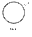
- Fig. 2 is a view showing the sectional shape of the inner pipe 6 in a direction crossing the central axis A at right angles.
- the inner pipe 6 is a pipe-shaped member having its center on the central axis A.
- the mat 5 is arranged to sandwich or clamp the inner pipe 6 therein, whereby it is divided into a portion at the side of the case 4 and a portion at the side of the catalyst carrier 3 by means of the inner pipe 6.
- the mat 5 is formed of an electric insulation material.
- a material which forms the mat 5 there can be exemplified a ceramic fiber which includes alumina as a main component.
- the mat 5 is wound around the outer peripheral surface of the catalyst carrier 3 and the outer peripheral surface of the inner pipe 6.
- the mat 5 is divided into an upstream side portion 5a and a downstream side portion 5b, and a space is formed between the upstream side portion 5a and the downstream side portion 5b. Due to the insertion of the mat 5 between the catalyst carrier 3 and the case 4, it is possible to suppress electricity from flowing into the case 4 at the time when the catalyst carrier 3 is electrically energized.
- the inner pipe 6 is formed of an electrically insulating material. Moreover, the inner pipe 6 is formed of a material which is more resistant to water permeation than the mat 5. Alumina can be exemplified as a material which forms the inner pipe 6. As shown in Fig. 1 , the inner pipe 6 has a length in the direction of the central axis A longer than that of the mat 5. As a result, the inner pipe 6 has an upstream side end and a downstream side end thereof protruded from an upstream side end face and a downstream side end face of the mat 5, respectively. In the following, those portions 6a, 6b of the inner pipe 6 which protrude from the end faces of the mat 5 into the exhaust gas are referred to as "protrusion portions".
- the case 4 and the inner pipe 6 have through holes 4d, 6c opened therein so as to allow the electrodes 7 to pass them, respectively.
- the electrode chamber 9 is formed by a space between the upstream side portion 5a and the downstream side portion 5b of the mat 5 in the case 4.
- the electrode chamber 9 is formed over the entire circumference of the outer peripheral surface of the catalyst carrier 3 between the upstream side portion 5a and the downstream side portion 5b of the mat 5.
- Electrode support members 8, which serve to support the electrodes 7, respectively, are arranged in the through holes 4d which are opened in the case 4. These electrode support members 8 are each formed of an electrically insulating material, and are fitted with no gap between the case 4 and the the electrodes 7.
- FIG. 3 is an enlarged view showing the schematic construction of the upstream side protrusion portion 6a of the inner pipe 6.
- the downstream side protrusion portion 6b of the inner pipe 6 also has the same construction.
- the protrusion portion 6a of the inner pipe 6 is formed with precious metal bands 10 which extend around on the outer peripheral surface thereof.
- the precious metal bands 10 are formed by coating a precious metal (Pt, Ag, etc.) on the outer peripheral surface of the protrusion portion 6a in a band-shaped manner so as to extend around on the circumferential surface thereof.
- the intervals between the adjacent precious metal bands 10 are set to be a predetermined interval W1, as shown in Fig. 3 .
- the predetermined interval W1 is an interval which is equal to or larger than a lower limit value of an interval which can ensure electrical insulation between the adjacent precious metal bands 10.
- the intervals between the adjacent precious metal bands 10 may not necessarily be an equal interval as long as they can ensure electrical insulation therebetween.
- the catalyst carrier 3 corresponds to a heat generation element according to the present invention.
- the heat generation element according to the present invention is not limited to a carrier which supports a catalyst, but instead the heat generation element may be a structure which is arranged at an upstream side of a catalyst, for example.
- the case 4 corresponds to a case according to the present invention
- the mat 5 corresponds to an insulating support member according to the present invention.
- the inner pipe 6 corresponds to an inner pipe according to the present invention
- the precious metal bands 10 corresponds to precious metal bands according to the present invention.
- condensed water in the exhaust pipe 2 or in the case 4, condensed water may be generated due to condensation of the moisture in the exhaust gas.
- the condensed water reaches from the inner wall surface of the case 4 up to the catalyst carrier 3 while transmitting through the inside of the mat 5 or the end faces thereof, the case 4 and the catalyst carrier 3 are short circuited to each other.
- the inner pipe 6 is inserted in the mat 5.
- the inner pipe 6 protrudes from the end faces of the mat 5.
- the inner pipe 6 need not necessarily protrude from both the upstream side and the downstream side of the mat 5.
- the construction may also be such that a protrusion portion of the inner pipe 6 is formed only at the upstream side of the mat at which an amount of generation of condensed water is more than that at the downstream side thereof.
- the PM in the exhaust gas adheres to and accumulates or deposits on the end faces of the mat 5 and the protrusion portions 6a, 6b of the inner pipe 6.
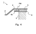
- the PM deposits over the entire surfaces of the end face of the mat 5 and the surface of the protrusion portion 6a (or 6b) of the inner pipe 6, there occurs a short circuit between the case 4 and the catalyst carrier 3 through the PM, as shown in Fig. 4 .
- the protrusion portions 6a, 6b of the inner pipe 6 are formed with the precious metal bands 10 which extend around on the outer peripheral surfaces thereof. Then, the PM is oxidized and removed by the active oxygen which is generated by the precious metal bands 10. With this, the electrical insulation between the case 4 and the catalyst carrier 3 is suppressed from being reduced resulting from the PM.
- the precious metal bands 10 are formed of Pt
- NOx in the exhaust gas is reduced by Pt, so that NO 2 is generated.
- the PM is oxidized also by the NO 2 .
- the precious metal bands 10 are formed of a platinum based metal (Rh, Pd, etc.) other than Pt
- the PM is oxidized also by NO 2 which has been generated by the reduction of NOx in the exhaust gas.
- Fig. 5 is an image view showing a state in which PM has been deposited on the surface of the protrusion portion 6a of the inner pipe 6, and a state in which the PM thus deposited has been oxidized.
- Fig. 5(a) shows the state in which the PM has been deposited on the surface of the protrusion portion 6a of the inner pipe 6, and
- Fig. 5(b) shows the state at the time when the PM has been oxidized.
- the PM is deposited on the entire surface of the protrusion portion 6a of the inner pipe 6 on the surface, i.e., on the surfaces of the precious metal bands 10 and those portions of the protrusion portion 6a on which the precious metal bands 10 are not formed. Then, the PM thus deposited on the precious metal bands 10 is oxidized and removed by means of the active oxygen (in the case of Pt, NO 2 in addition thereto) generated in the precious metal bands 10.
- the active oxygen generated in the precious metal bands 10 also oxidizes PM deposited at locations which are slightly away from the precious metal bands 10. As a result, even if the PM remains unoxidized on the surface of the protrusion portion 6a of the inner pipe 6 at locations between the precious metal bands 10, it is possible to ensure a creepage distance between the PM and each of the precious metal bands 10, as shown by L1.
- the precious metal bands 10 are formed on the outer peripheral surface of the protrusion portion 6a of the inner pipe 6 in a band-shaped fashion so as to extend around on the circumferential surface thereof, and hence it is possible to ensure such a creepage distance L1 over the entire circumference of the protrusion portion 6a of the inner pipe 6.
- the number of the precious metal bands 10 formed on the surfaces of the protrusion portions 6a, 6b of the inner pipe 6 may be decided in such a manner that the total sum of the creepage distances L1 obtained by oxidizing and removing the PM is a distance capable to maintain the electrical insulation between the catalyst carrier 3 and the case 4 to a sufficient extent.
- the number of the precious metal bands 10 may not necessarily be plural as long as the electrical insulation between the catalyst carrier 3 and the case 4 can be maintained to a sufficient extent.
- Fig. 6 shows a state in which the PM has been deposited relatively thickly on the surface of the protrusion portion 6a of the inner pipe 6.
- the PM at locations in contact with the precious metal bands 10 and at locations slightly away from the precious metal bands 10 is oxidized by active oxygen.
- the layer of the PM formed on the precious metal bands 10 is thick, and hence, if there exists any PM which the active oxygen generated in the precious metal bands 10 does not reach, that PM will remain on the surface of the protrusion portion 6a without being oxidized.
- the PM remaining in this manner tends to peel off easily.
- the PM is exfoliated by the flow of the exhaust gas, as shown in Fig. 6 . Accordingly, according to this embodiment, the entire layer of the deposited PM can be removed.
- a precious metal band(s) 10 may be formed on an inner peripheral surface(s) of a protrusion portion (s) of the inner pipe 6, as shown in Fig. 7 .
- the precious metal band(s) 10 may be formed on both the outer peripheral surface(s) and the inner peripheral surface(s) of the protrusion portion(s) of the inner pipe 6.
- the inner pipe 6 is not inserted in the mat 5, but may be inserted or sandwiched between the outer peripheral surface of the mat 5 and the inner peripheral surface of the case 4, as shown in Fig. 8 .
- the precious metal bands 10 can be formed on the inner peripheral surfaces of the protrusion portions 6a, 6b of the inner pipe 6.
- Fig. 9 is a view showing the schematic construction of protrusion portions 6a, 6b at an upstream side and a downstream side of an inner pipe 6 in an EHC 1 according to this second embodiment.
- precious metal bands 10a, 10b are formed on the protrusion portions 6a, 6b at both the upstream side and the downstream side of the inner pipe 6.
- this embodiment is different from the first embodiment in that in this embodiment, the precious metal bands 10a formed on the upstream side protrusion portion 6a (hereinafter referred to as upstream side precious metal bands) and the precious metal bands 10b formed on the downstream side protrusion portion 6b (hereinafter referred to as downstream side precious metal bands) are formed of different precious metals, respectively.
- the construction of the second embodiment other than this is the same as that of the EHC according to the first embodiment.
- the downstream side precious metal bands 10b are formed of Ag, whereas the upstream side precious metal bands 10a are formed of a platinum based metal whose activity is higher than Ag.
- the combination of the precious metals which form both the precious metal bands 10a, 10b is not limited to this, but the upstream side precious metal bands 10a should just be formed of a precious metal which is higher in activity than a precious metal which forms the downstream side precious metal bands 10b.
- the temperature of the exhaust gas which flows into the EHC 1 is low as compared with the temperature of the exhaust gas which flows out of the EHC 1. This is because the temperature of the exhaust gas is caused to rise by reaction heat in the exhaust gas purification catalyst 13 in the inside of the EHC 1.
- the temperature of the exhaust gas is low, PM is more difficult to be oxidized as compared with the case where the temperature of the exhaust gas is high. Therefore, in the inner pipe 6 of the EHC 1, the PM deposited on the upstream side protrusion portion 6a is more difficult to be oxidized as compared with that on the downstream side protrusion portion 6b.
- the downstream side precious metal bands 10b are formed of Ag
- the upstream side precious metal bands 10a are formed of a platinum based metal whose activity is higher than Ag. According to this, in the upstream side protrusion portion 6a, too, in which the temperature of the exhaust gas is low, the oxidization of PM can be facilitated by active oxygen. As a result, it is possible to suppress a reduction in the insulation between the catalyst carrier 3 and the case 4 resulting from the PM with a higher degree of probability.
- the downstream side precious metal bands 10b are formed of Ag which is less expensive than the platinum based metal.
Landscapes
- Chemical & Material Sciences (AREA)
- Engineering & Computer Science (AREA)
- Chemical Kinetics & Catalysis (AREA)
- Health & Medical Sciences (AREA)
- Combustion & Propulsion (AREA)
- Toxicology (AREA)
- Mechanical Engineering (AREA)
- General Engineering & Computer Science (AREA)
- Biomedical Technology (AREA)
- Environmental & Geological Engineering (AREA)
- Analytical Chemistry (AREA)
- General Chemical & Material Sciences (AREA)
- Oil, Petroleum & Natural Gas (AREA)
- Exhaust Gas After Treatment (AREA)
- Catalysts (AREA)
- Exhaust Gas Treatment By Means Of Catalyst (AREA)
Abstract
Description
- The present invention relates to an electric heating catalyst that is arranged in an exhaust passage of an internal combustion engine.
- In the past, as an exhaust gas purification catalyst arranged in an exhaust passage of an internal combustion engine, there has been developed an electric heating catalyst (hereinafter referred to as an EHC) in which a catalyst is heated by means of a heat generation element which generates heat by electrical energization thereof.
- In the EHC, an insulating support member, which serves to support the heat generation element and to insulate electricity, is arranged between the heat generation element which generates heat by electrical energization thereof, and a case in which the heat generation element is received. For example, in
Patent Document 1, there is disclosed a technique in which in an EHC, a mat of an insulating material is arranged between a carrier which is electrically energized to generate heat and a case in which the carrier is received. - In addition, in
Patent Document 2, there has been disclosed a technique related to a condensation device which causes exhaust gas fine particles to be charged and condensed by generating a corona discharge in an exhaust pipe of an internal combustion engine. The condensation device inPatent Document 2 has an electric conductive part that serves to conduct a high voltage to an electric discharge part, and an insulator part that serves to hold an outer periphery of the electric conductive part. A ringshaped protrusion portion is formed to protrude from an outer peripheral surface of the insulator part in a diametrical direction thereof, and an oxidation catalyst layer is formed in the protrusion portion. - In
Patent Document 3, there is described that in a filter substrate of a catalyst for purification of diesel exhaust gas, an inflow side oxidation catalyst coat layer, which includes at least one kind of substance selected from alkali metals and alkaline earth metals, is formed on a cell partition surface at the side of an inflow side cell, and an outflow side oxidation catalyst coat layer, which does not include an alkali metal and an alkaline earth metal, is formed on a cell partition surface at the side of an outflow side cell. -
- Patent Document 1: Japanese patent application laid-open No.
H05-269387 - Patent Document 2: Japanese patent application laid-open No.
2006-342730 - Patent Document 3: Japanese patent application laid-open No.
2007-117954 - In addition, in the exhaust pipe or in the case of the EHC, condensed water may be generated due to condensation of the moisture in the exhaust gas. If the condensed water permeates into the insulating support member, there is a fear that the heat generation element and the case may be short circuited to each other through the condensed water. Accordingly, in the EHC, an inner pipe may be provided which is sandwiched or clamped by the insulating support member in such a manner as to locate between the heat generation element and the case. In this case, the inner pipe is formed of a material which insulates electricity and into which the condensed water is difficult to permeate.
- By arranging the inner pipe in such a manner, the condensed water, which has flowed on the inner wall surface of the case and permeated into the insulating support member, is suppressed from reaching up to the heat generation element in the inside of the insulating support member. As a result, the heat generation element and the case are suppressed from being short circuited to each other through the condensed water.
- In addition, in the case of the provision of the inner pipe in the EHC, the inner pipe is formed in a manner so as to protrude from an end face of the insulating support member into the exhaust gas. By forming the insulating support member in such a manner, the condensed water, which has flowed on the inner wall surface of the case and reached the insulating support member, is suppressed from reaching up to the heat generation element while transmitting through the end face of the insulating support member. Accordingly, it is possible to suppress the short circuit between the heat generation element and the case through the condensed water on the end face of the insulating support member.
- However, if such an inner pipe is provided, particulate matter (hereinafter referred to as PM) in the exhaust gas will adhere to and accumulate or deposit on the protrusion portion which protrudes from the end face of the insulating support member in the inner pipe. Because the PM has conductivity, when the PM deposits on the protrusion portion of the inner pipe, there is a possibility that the insulation between the heat generation element and the case may be reduced.
- The present invention has been made in view of such problems as referred to above, and has for its object to suppress a reduction in insulation between a heat generation element and a case resulting from PM in an EHC.
- The present invention resides in an EHC which has an inner pipe arranged so as to be located between a heat generation element and a case, wherein a precious metal band is formed on at least either one of an inner peripheral surface and an outer peripheral surface of that portion of the inner pipe which protrudes from an end face of an insulating support member into an exhaust gas in such a manner as to extend around on a circumferential surface thereof.
- More specifically, an EHC according to the present invention is provided with:
- a heat generation element that is electrically energized to generate heat so that a catalyst is heated by the generation of heat;
- a case that receives said heat generation element therein;
- an insulating support member that is arranged between said heat generation element and said case for supporting said heat generation element and insulating electricity;
- an inner pipe that is a tubular member formed of a material which insulates electricity and which is more resistant to water permeation than said insulating support member, said inner pipe being arranged so as to be located between said heat generation element and said case, said inner pipe having an end protruding from an end face of said insulating support member into an exhaust gas; and
- a precious metal band that is formed on at least either one of an inner peripheral surface and an outer peripheral surface of that portion of said inner pipe which protrudes from the end face of said insulating support member into the exhaust gas, by coating thereon precious metal in a band-shaped manner so as to extend around on a circumferential surface thereof.
- In the EHC according to the present invention, the inner pipe, which is located between the heat generation element and the case, is arranged by being inserted in the insulating support member, or by being inserted or sandwiched between an inner wall surface of the case and the insulating support member. In addition, the end of the inner pipe protrudes from the end face of the insulating support member into the exhaust gas. In the following, that portion of the inner pipe which protrudes from the end face of the insulating support member into the exhaust gas is referred to as a "protrusion portion".
- In addition, the precious metal band is formed on at least either one of the inner peripheral surface and the outer peripheral surface of the protrusion portion of the inner pipe in such a manner as to extend around on the circumferential surface thereof. Active oxygen is generated on the precious metal band. The PM deposited on the precious metal band is oxidized by the active oxygen. Further, by means of the active oxygen, there can also be oxidized the PM which has been deposited on the inner peripheral surface or the outer peripheral surface of the protrusion portion of the inner pipe at a location in the vicinity of the precious metal band. As a result, it is possible to suppress the PM from depositing over the entire surfaces of the end face of the insulating support member, and the inner peripheral surface and the outer peripheral surface of the protrusion portion of the inner pipe. Thus, according to the present invention, it is possible to suppress a reduction in the insulation between the heat generation element and the case resulting from the PM.
- In the present invention, the precious metal band may be formed in plurality on at least either one of the inner peripheral surface and the outer peripheral surface of the protrusion portion of the inner pipe. In this case, the plurality of precious metal bands are formed at such intervals that electrical insulation between adjacent precious metal bands can be ensured.
- As described above, in the present invention, not only the PM deposited on the precious metal bands but also the PM deposited at locations in the vicinity of the precious metal bands are oxidized by the active oxygen generated on the precious metal bands. As a result, by arranging the precious metal bands in plurality, it becomes possible to ensure a longer creepage distance for insulation.
- Here, note that in cases where three or more precious metal bands are arranged on the inner peripheral surface or the outer peripheral surface of the protrusion portion of the inner pipe, the intervals between the adjacent precious metal bands may not necessarily be constant as long as they can ensure electrical insulation therebetween.
- In the EHC according to the present invention, in cases where the inner pipe has its ends protruding respectively from both the upstream side and the downstream side end faces of the insulating support member into the exhaust gas, a precious metal band is provided on each of the upstream side protrusion portion and the downstream side protrusion portion of the inner pipe. Here, note that the temperature of the exhaust gas which flows into the EHC is lower as compared with the temperature of the exhaust gas which flows out of the EHC. Therefore, in the upstream side protrusion portion of the inner pipe, the PM deposited thereon is more difficult to be oxidized as compared with that on the downstream side protrusion portion.
- Accordingly, the precious metal band formed on the upstream side protrusion portion may be formed of a precious metal which is higher in activity than a precious metal which forms the precious metal band formed on the downstream side protrusion portion. According to this, it is possible to carry out the oxidization of the PM deposited on the upstream side protrusion portion in a more facilitated manner.
- In the above-mentioned case, for example, in the upstream side protrusion portion, the precious metal band may be formed of a platinum based metal, whereas in the downstream side protrusion portion, the precious metal band may be formed of Ag. According to the platinum based metal, the PM can be oxidized not only by the active oxygen but also by the oxygen generated at the time of reducing the NOx in the exhaust gas. Accordingly, it is possible to facilitate the oxidization of the PM deposited on the upstream side protrusion portion in a more effective manner. In addition, in the downstream side protrusion portion, the precious metal band is formed of Ag, whereby the reduction of cost can be attained, as compared with the case where the precious metal bands are formed of the platinum based metal in both of the upstream side and downstream side protrusion portions.
- According to the present invention, it is possible to suppress a reduction in the insulation between the heat generation element and the case resulting from PM in the EHC.
-
-
Fig. 1 is a view showing the schematic construction of an electric heating catalyst (EHC) according to a first embodiment of the present invention. -
Fig. 2 is a view showing a sectional shape of an inner pipe in a direction crossing a central axis thereof at right angles according to the first embodiment. -
Fig. 3 is a view showing the schematic construction of a protrusion portion at an upstream side of the inner pipe according to the first embodiment. -
Fig. 4 is a view showing a state in which PM has been accumulated or deposited over the entire surfaces of an end face of a mat and a surface of a protrusion portion of the inner pipe. -
Fig. 5 is an image view showing a state in which PM has been deposited on the surface of the protrusion portion of the inner pipe, and a state in which the PM thus deposited has been oxidized, according to the first embodiment. -
Fig. 6 shows a state in which PM has been deposited relatively thickly on the surface of the protrusion portion of the inner pipe according to the first embodiment. -
Fig. 7 is a view showing another construction of precious metal bands according to the first embodiment. -
Fig. 8 is a view showing another construction of the electric heating' catalyst (EHC) according to the first embodiment. -
Fig. 9 is a view showing the schematic construction of protrusion portions at an upstream side and a downstream side of an inner pipe according to a second embodiment. - Hereinafter, specific embodiments of the present invention will be described based on the attached drawings. However, the dimensions, materials, shapes, relative arrangements and so on of component parts described in the embodiments are not intended to limit the technical scope of the present invention to these alone in particular as long as there are no specific statements.
-
Figs. 1 through 3 are views each showing the schematic construction of an electric heating catalyst (EHC) according to this first embodiment of the present invention. TheEHC 1 according to this embodiment is arranged in an exhaust pipe of an internal combustion engine mounted on a vehicle. The internal combustion engine may be a diesel engine, or may be a gasoline engine. In addition, theEHC 1 according to this embodiment can also be used in a vehicle which adopts a hybrid system equipped with an electric motor. - The
EHC 1 according to this embodiment is provided with acatalyst carrier 3, acase 4, amat 5, aninner pipe 6, andelectrodes 7. Thecatalyst carrier 3 is formed in the shape of a circular cylinder, and is arranged in such a manner that a central axis thereof is in alignment with a central axis A of anexhaust pipe 2. An exhaustgas purification catalyst 13 is carried or supported by thecatalyst carrier 3. As the exhaustgas purification catalyst 13, there can be exemplified an oxidation catalyst, an NOx storage reduction catalyst, an NOx selective reduction catalyst, a three-way catalyst, and so on. - The
catalyst carrier 3 is formed of a material which, when energized, becomes an electric resistance to generate heat. As a material for thecatalyst carrier 3, there can be exemplified SiC. Thecatalyst carrier 3 has a plurality of passages which extend in a direction in which an exhaust gas flows (i.e., the direction of the central axis A), and which have a cross section of honeycomb shape vertical to the direction in which the exhaust gas flows. The exhaust gas flows through these passages. Here, note that the cross sectional shape of thecatalyst carrier 3 in the direction orthogonal to the central axis A may be elliptical, etc. The central axis A is a central axis common to theexhaust pipe 2, thecatalyst carrier 3, theinner pipe 6, and thecase 4. - The
catalyst carrier 3 is received in thecase 4. Anelectrode chamber 9 is formed in thecase 4. Here, note that the details of theelectrode chamber 9 will be described later. One pair ofelectrodes 7 are connected to thecatalyst carrier 3 through theelectrode chamber 9 from right and left directions. Electricity is supplied to theelectrodes 7 from a battery (not shown). When electricity is supplied to theelectrodes 7, thecatalyst carrier 3 is electrically energized. When thecatalyst carrier 3 generates heat by energization thereof, the exhaustgas purification catalyst 13 supported by thecatalyst carrier 3 is heated, so that the activation thereof is facilitated. - The
case 4 is formed of metal. As a material which forms thecase 4, there can be exemplified a stainless steel material. Thecase 4 has areception portion 4a which is constructed to include a curved surface parallel to the central axis A, andtapered portions reception portion 4a and theexhaust pipe 2 with each other at an upstream side and a downstream side, respectively, of thereception portion 4a. Thereception portion 4a has a passage cross sectional area which is larger than that of theexhaust pipe 2, and thecatalyst carrier 3, themat 5 and theinner pipe 6 are received in the inside of thereception portion 4a. Thetapered portions reception portion 4a. - The
mat 5 is inserted between an inner wall surface of thereception portion 4a of thecase 4, and an outer peripheral surface of thecatalyst carrier 3. In other words, inside thecase 4, thecatalyst carrier 3 is supported by themat 5. In addition, theinner pipe 6 is inserted in themat 5.Fig. 2 is a view showing the sectional shape of theinner pipe 6 in a direction crossing the central axis A at right angles. As shown inFigs. 1 and2 , theinner pipe 6 is a pipe-shaped member having its center on the central axis A. Themat 5 is arranged to sandwich or clamp theinner pipe 6 therein, whereby it is divided into a portion at the side of thecase 4 and a portion at the side of thecatalyst carrier 3 by means of theinner pipe 6. - The
mat 5 is formed of an electric insulation material. As a material which forms themat 5, there can be exemplified a ceramic fiber which includes alumina as a main component. Themat 5 is wound around the outer peripheral surface of thecatalyst carrier 3 and the outer peripheral surface of theinner pipe 6. In addition, themat 5 is divided into anupstream side portion 5a and adownstream side portion 5b, and a space is formed between theupstream side portion 5a and thedownstream side portion 5b. Due to the insertion of themat 5 between thecatalyst carrier 3 and thecase 4, it is possible to suppress electricity from flowing into thecase 4 at the time when thecatalyst carrier 3 is electrically energized. - The
inner pipe 6 is formed of an electrically insulating material. Moreover, theinner pipe 6 is formed of a material which is more resistant to water permeation than themat 5. Alumina can be exemplified as a material which forms theinner pipe 6. As shown inFig. 1 , theinner pipe 6 has a length in the direction of the central axis A longer than that of themat 5. As a result, theinner pipe 6 has an upstream side end and a downstream side end thereof protruded from an upstream side end face and a downstream side end face of themat 5, respectively. In the following, thoseportions inner pipe 6 which protrude from the end faces of themat 5 into the exhaust gas are referred to as "protrusion portions". - The
case 4 and theinner pipe 6 have throughholes electrodes 7 to pass them, respectively. Then, theelectrode chamber 9 is formed by a space between theupstream side portion 5a and thedownstream side portion 5b of themat 5 in thecase 4. In other words, in this embodiment, theelectrode chamber 9 is formed over the entire circumference of the outer peripheral surface of thecatalyst carrier 3 between theupstream side portion 5a and thedownstream side portion 5b of themat 5. -
Electrode support members 8, which serve to support theelectrodes 7, respectively, are arranged in the throughholes 4d which are opened in thecase 4. Theseelectrode support members 8 are each formed of an electrically insulating material, and are fitted with no gap between thecase 4 and the theelectrodes 7. - Here, the construction of the
protrusion portions inner pipe 6 according to this embodiment will be explained.Fig. 3 is an enlarged view showing the schematic construction of the upstreamside protrusion portion 6a of theinner pipe 6. Here, note that the downstreamside protrusion portion 6b of theinner pipe 6 also has the same construction. - In this embodiment, the
protrusion portion 6a of theinner pipe 6 is formed withprecious metal bands 10 which extend around on the outer peripheral surface thereof. Theprecious metal bands 10 are formed by coating a precious metal (Pt, Ag, etc.) on the outer peripheral surface of theprotrusion portion 6a in a band-shaped manner so as to extend around on the circumferential surface thereof. - In addition, the intervals between the adjacent
precious metal bands 10 are set to be a predetermined interval W1, as shown inFig. 3 . Here, the predetermined interval W1 is an interval which is equal to or larger than a lower limit value of an interval which can ensure electrical insulation between the adjacentprecious metal bands 10. Here, note that the intervals between the adjacentprecious metal bands 10 may not necessarily be an equal interval as long as they can ensure electrical insulation therebetween. - Here, note that in this embodiment, the
catalyst carrier 3 corresponds to a heat generation element according to the present invention. However, the heat generation element according to the present invention is not limited to a carrier which supports a catalyst, but instead the heat generation element may be a structure which is arranged at an upstream side of a catalyst, for example. In addition, in this embodiment, thecase 4 corresponds to a case according to the present invention, and themat 5 corresponds to an insulating support member according to the present invention. Also, in this embodiment, theinner pipe 6 corresponds to an inner pipe according to the present invention, and theprecious metal bands 10 corresponds to precious metal bands according to the present invention. - In the
EHC 1 according to the present invention, in theexhaust pipe 2 or in thecase 4, condensed water may be generated due to condensation of the moisture in the exhaust gas. When the condensed water reaches from the inner wall surface of thecase 4 up to thecatalyst carrier 3 while transmitting through the inside of themat 5 or the end faces thereof, thecase 4 and thecatalyst carrier 3 are short circuited to each other. - However, in this embodiment, the
inner pipe 6 is inserted in themat 5. In addition, theinner pipe 6 protrudes from the end faces of themat 5. With theinner pipe 6 being formed in this manner, a flow of the condensed water from the inner wall surface of thecase 4 to thecatalyst carrier 3 in the inside of themat 5 and on the end faces thereof is interrupted or blocked by theinner pipe 6. Accordingly, it is possible to suppress a short circuit between thecase 4 and thecatalyst carrier 3 through the condensed water. - Here, note that in this embodiment, the
inner pipe 6 need not necessarily protrude from both the upstream side and the downstream side of themat 5. For example, the construction may also be such that a protrusion portion of theinner pipe 6 is formed only at the upstream side of the mat at which an amount of generation of condensed water is more than that at the downstream side thereof. - In addition, in the
EHC 1, the PM in the exhaust gas adheres to and accumulates or deposits on the end faces of themat 5 and theprotrusion portions inner pipe 6. As a result, when the PM deposits over the entire surfaces of the end face of themat 5 and the surface of theprotrusion portion 6a (or 6b) of theinner pipe 6, there occurs a short circuit between thecase 4 and thecatalyst carrier 3 through the PM, as shown inFig. 4 . - However, in this embodiment, the
protrusion portions inner pipe 6 are formed with theprecious metal bands 10 which extend around on the outer peripheral surfaces thereof. Then, the PM is oxidized and removed by the active oxygen which is generated by theprecious metal bands 10. With this, the electrical insulation between thecase 4 and thecatalyst carrier 3 is suppressed from being reduced resulting from the PM. - Here, reference will be made to a mechanism of oxidation of the PM, while taking, as an example, a case in which the
precious metal bands 10 are formed of Pt. In cases where theprecious metal bands 10 are formed of Pt, when the temperature of theprecious metal bands 10 rises due to the heat of the exhaust gas, active oxygen is generated from platinum oxide, as shown in the following equation (1). Then, the PM is oxidized by the active oxygen.
PtO2 → Pt4+ + 202- ... Equation (1)
- Further, in cases where the
precious metal bands 10 are formed of Pt, NOx in the exhaust gas is reduced by Pt, so that NO2 is generated. The PM is oxidized also by the NO2. Similarly, in cases where theprecious metal bands 10 are formed of a platinum based metal (Rh, Pd, etc.) other than Pt, the PM is oxidized also by NO2 which has been generated by the reduction of NOx in the exhaust gas. -
Fig. 5 is an image view showing a state in which PM has been deposited on the surface of theprotrusion portion 6a of theinner pipe 6, and a state in which the PM thus deposited has been oxidized.Fig. 5(a) shows the state in which the PM has been deposited on the surface of theprotrusion portion 6a of theinner pipe 6, andFig. 5(b) shows the state at the time when the PM has been oxidized. - As shown in
Fig. 5(a) , the PM is deposited on the entire surface of theprotrusion portion 6a of theinner pipe 6 on the surface, i.e., on the surfaces of theprecious metal bands 10 and those portions of theprotrusion portion 6a on which theprecious metal bands 10 are not formed. Then, the PM thus deposited on theprecious metal bands 10 is oxidized and removed by means of the active oxygen (in the case of Pt, NO2 in addition thereto) generated in theprecious metal bands 10. - Further, the active oxygen generated in the
precious metal bands 10 also oxidizes PM deposited at locations which are slightly away from theprecious metal bands 10. As a result, even if the PM remains unoxidized on the surface of theprotrusion portion 6a of theinner pipe 6 at locations between theprecious metal bands 10, it is possible to ensure a creepage distance between the PM and each of theprecious metal bands 10, as shown by L1. In this embodiment, theprecious metal bands 10 are formed on the outer peripheral surface of theprotrusion portion 6a of theinner pipe 6 in a band-shaped fashion so as to extend around on the circumferential surface thereof, and hence it is possible to ensure such a creepage distance L1 over the entire circumference of theprotrusion portion 6a of theinner pipe 6. - Moreover, by forming the plurality of
precious metal bands 10 on the surface of theprotrusion portion 6a of theinner pipe 6, a total sum of the creepage distances L1 obtained by oxidizing and removing the PM can be made longer. As a result, according to this embodiment, it is possible to suppress a reduction in the insulation between thecatalyst carrier 3 and thecase 4 resulting from the PM. - Here, note that in this embodiment, the number of the
precious metal bands 10 formed on the surfaces of theprotrusion portions inner pipe 6 may be decided in such a manner that the total sum of the creepage distances L1 obtained by oxidizing and removing the PM is a distance capable to maintain the electrical insulation between thecatalyst carrier 3 and thecase 4 to a sufficient extent. In addition, the number of theprecious metal bands 10 may not necessarily be plural as long as the electrical insulation between thecatalyst carrier 3 and thecase 4 can be maintained to a sufficient extent. - In addition,
Fig. 6 shows a state in which the PM has been deposited relatively thickly on the surface of theprotrusion portion 6a of theinner pipe 6. Even in such a case, the PM at locations in contact with theprecious metal bands 10 and at locations slightly away from theprecious metal bands 10 is oxidized by active oxygen. At this time, the layer of the PM formed on theprecious metal bands 10 is thick, and hence, if there exists any PM which the active oxygen generated in theprecious metal bands 10 does not reach, that PM will remain on the surface of theprotrusion portion 6a without being oxidized. However, the PM remaining in this manner tends to peel off easily. For this reason, the PM is exfoliated by the flow of the exhaust gas, as shown inFig. 6 . Accordingly, according to this embodiment, the entire layer of the deposited PM can be removed. - In this embodiment, a precious metal band(s) 10 may be formed on an inner peripheral surface(s) of a protrusion portion (s) of the
inner pipe 6, as shown inFig. 7 . In this case, on the inner peripheral surface(s), a creepage distance for insulation can be ensured. Accordingly, the same effects as stated above can be obtained. In addition, the precious metal band(s) 10 may be formed on both the outer peripheral surface(s) and the inner peripheral surface(s) of the protrusion portion(s) of theinner pipe 6. - Moreover, in this embodiment, the
inner pipe 6 is not inserted in themat 5, but may be inserted or sandwiched between the outer peripheral surface of themat 5 and the inner peripheral surface of thecase 4, as shown inFig. 8 . Even in this case, theprecious metal bands 10 can be formed on the inner peripheral surfaces of theprotrusion portions inner pipe 6. -
Fig. 9 is a view showing the schematic construction ofprotrusion portions inner pipe 6 in anEHC 1 according to this second embodiment. In this embodiment, too, as in the case of the first embodiment,precious metal bands protrusion portions inner pipe 6. However, this embodiment is different from the first embodiment in that in this embodiment, theprecious metal bands 10a formed on the upstreamside protrusion portion 6a (hereinafter referred to as upstream side precious metal bands) and theprecious metal bands 10b formed on the downstreamside protrusion portion 6b (hereinafter referred to as downstream side precious metal bands) are formed of different precious metals, respectively. The construction of the second embodiment other than this is the same as that of the EHC according to the first embodiment. - In this embodiment, the downstream side
precious metal bands 10b are formed of Ag, whereas the upstream sideprecious metal bands 10a are formed of a platinum based metal whose activity is higher than Ag. However, the combination of the precious metals which form both theprecious metal bands precious metal bands 10a should just be formed of a precious metal which is higher in activity than a precious metal which forms the downstream sideprecious metal bands 10b. - The temperature of the exhaust gas which flows into the
EHC 1 is low as compared with the temperature of the exhaust gas which flows out of theEHC 1. This is because the temperature of the exhaust gas is caused to rise by reaction heat in the exhaustgas purification catalyst 13 in the inside of theEHC 1. When the temperature of the exhaust gas is low, PM is more difficult to be oxidized as compared with the case where the temperature of the exhaust gas is high. Therefore, in theinner pipe 6 of theEHC 1, the PM deposited on the upstreamside protrusion portion 6a is more difficult to be oxidized as compared with that on the downstreamside protrusion portion 6b. - Accordingly, in this embodiment, the downstream side
precious metal bands 10b are formed of Ag, whereas the upstream sideprecious metal bands 10a are formed of a platinum based metal whose activity is higher than Ag. According to this, in the upstreamside protrusion portion 6a, too, in which the temperature of the exhaust gas is low, the oxidization of PM can be facilitated by active oxygen. As a result, it is possible to suppress a reduction in the insulation between thecatalyst carrier 3 and thecase 4 resulting from the PM with a higher degree of probability. - Also, in other words, even if a precious metal, which is not as high in activity as that for the upstream side
precious metal bands 10a, is used for the downstream sideprecious metal bands 10b, the PM deposited on the downstreamside protrusion portion 6b can be oxidized and removed. Accordingly, in this embodiment, the downstream sideprecious metal bands 10b are formed of Ag which is less expensive than the platinum based metal. By so doing, it is possible to decrease the cost of theprecious metal bands catalyst carrier 3 and thecase 4 resulting from the PM. -
- 1:
- electric heating catalyst (EHC)
- 3:
- catalyst carrier
- 4:
- case
- 5:
- mat
- 6:
- inner pipe
- 7:
- electrodes
- 9:
- electrode chamber
- 10:
- precious metal bands
Claims (4)
- An electric heating type catalyst comprising:a heat generation element that is electrically energized to generate heat so that a catalyst is heated by the generation of heat;a case that receives said heat generation element therein;an insulating support member that is arranged between said heat generation element and said case for supporting said heat generation element and insulating electricity;an inner pipe that is a tubular member formed of a material which insulates electricity and which is more resistant to water permeation than said insulating support member, said inner pipe being arranged so as to be located between said heat generation element and said case, said inner pipe having an end protruding from an end face of said insulating support member into an exhaust gas; anda precious metal band that is formed on at least either one of an inner peripheral surface and an outer peripheral surface of that portion of said inner pipe which protrudes from the end face of said insulating support member into the exhaust gas, by coating thereon precious metal in a band-shaped manner so as to extend around on a circumferential surface thereof.
- The electric heating catalyst as set forth in claim 1, wherein
said precious metal band is formed in plurality on at least either one of the inner peripheral surface and the outer peripheral surface of that portion of said inner pipe which protrudes from the end face of said insulating support member into the exhaust gas, at intervals capable of ensuring electrical insulation between adjacent precious metal bands. - The electric heating catalyst as set forth in claim 1 or 2, wherein
said inner pipe has its ends protruding into the exhaust gas from both the upstream side and the downstream side end faces of said insulating support member, respepctively, and said precious metal band formed on that portion of said inner pipe which protrudes from the upstream side end face of said insulating support member is formed of a precious metal which is higher in activity than a precious metal which forms said precious metal band formed on that portion of said inner pipe which protrudes from the downstream side end face of said insulating support member. - The electric heating catalyst as set forth in claim 3, wherein
said precious metal band formed on that portion of said inner pipe which protrudes from the upstream side end face of said insulating support member is formed of a platinum based metal; and
said precious metal band formed on that portion of said inner pipe which protrudes from the downstream side end face of said insulating support member is formed of Ag.
Applications Claiming Priority (1)
| Application Number | Priority Date | Filing Date | Title |
|---|---|---|---|
| PCT/JP2010/069094 WO2012056531A1 (en) | 2010-10-27 | 2010-10-27 | Electric heating catalyst |
Publications (3)
| Publication Number | Publication Date |
|---|---|
| EP2634387A1 true EP2634387A1 (en) | 2013-09-04 |
| EP2634387A4 EP2634387A4 (en) | 2014-07-16 |
| EP2634387B1 EP2634387B1 (en) | 2015-05-06 |
Family
ID=45993287
Family Applications (1)
| Application Number | Title | Priority Date | Filing Date |
|---|---|---|---|
| EP20100856826 Not-in-force EP2634387B1 (en) | 2010-10-27 | 2010-10-27 | Electric heating catalyst |
Country Status (5)
| Country | Link |
|---|---|
| US (1) | US8647584B2 (en) |
| EP (1) | EP2634387B1 (en) |
| JP (1) | JP5472457B2 (en) |
| CN (1) | CN102596409B (en) |
| WO (1) | WO2012056531A1 (en) |
Families Citing this family (3)
| Publication number | Priority date | Publication date | Assignee | Title |
|---|---|---|---|---|
| JP6408865B2 (en) * | 2014-10-28 | 2018-10-17 | イビデン株式会社 | Electric heating type catalytic converter |
| FR3103517B1 (en) | 2019-11-22 | 2021-10-29 | Faurecia Systemes Dechappement | Exhaust gas heater with metal foam heating element |
| DE102021122083A1 (en) * | 2021-08-26 | 2023-03-02 | Purem GmbH | exhaust gas heater |
Family Cites Families (17)
| Publication number | Priority date | Publication date | Assignee | Title |
|---|---|---|---|---|
| US5070694A (en) * | 1990-10-31 | 1991-12-10 | W. R. Grace & Co. -Conn. | Structure for electrically heatable catalytic core |
| US5238650A (en) * | 1991-09-13 | 1993-08-24 | W. R. Grace & Co.-Conn. | Electrode feed through |
| JPH0596421A (en) | 1991-10-01 | 1993-04-20 | Hitachi Seiko Ltd | Wire electric discharge machining device |
| JPH05269387A (en) | 1992-03-26 | 1993-10-19 | Nissan Motor Co Ltd | Exhaust gas purifying catalystic converter |
| JPH0596421U (en) * | 1992-05-26 | 1993-12-27 | カルソニック株式会社 | Electrode structure of electrothermal catalyst carrier |
| JPH062534A (en) * | 1992-06-19 | 1994-01-11 | Mazda Motor Corp | Exhaust gas purification device |
| JP3562004B2 (en) * | 1995-02-02 | 2004-09-08 | 日産自動車株式会社 | Catalyst purification device for internal combustion engine |
| US5846495A (en) * | 1995-07-12 | 1998-12-08 | Engelhard Corporation | Structure for converter body |
| JP3216545B2 (en) * | 1996-01-26 | 2001-10-09 | トヨタ自動車株式会社 | Exhaust purification catalyst device for internal combustion engine |
| JP3181219B2 (en) * | 1996-02-06 | 2001-07-03 | トヨタ自動車株式会社 | Electric heating type catalyst device |
| JP4284588B2 (en) * | 2003-01-10 | 2009-06-24 | トヨタ自動車株式会社 | Exhaust gas purification filter catalyst |
| JP4292511B2 (en) | 2004-06-21 | 2009-07-08 | トヨタ自動車株式会社 | Exhaust gas purification device |
| JP4678596B2 (en) * | 2004-11-29 | 2011-04-27 | 株式会社豊田中央研究所 | Exhaust purification device and exhaust purification system |
| GB0507326D0 (en) * | 2005-04-12 | 2005-05-18 | Delphi Tech Inc | Catalytic converter apparatus and method |
| JP4483714B2 (en) | 2005-06-09 | 2010-06-16 | 株式会社デンソー | Exhaust treatment device for internal combustion engine |
| JP2007117954A (en) * | 2005-10-31 | 2007-05-17 | Toyota Motor Corp | Diesel exhaust gas purification catalyst |
| JP5269387B2 (en) | 2006-09-25 | 2013-08-21 | シリコン イメージ,インコーポレイテッド | Signal interleaving for serial clock and data recovery |
-
2010
- 2010-10-27 WO PCT/JP2010/069094 patent/WO2012056531A1/en not_active Ceased
- 2010-10-27 EP EP20100856826 patent/EP2634387B1/en not_active Not-in-force
- 2010-10-27 CN CN201080039426.8A patent/CN102596409B/en not_active Expired - Fee Related
- 2010-10-27 US US13/394,825 patent/US8647584B2/en not_active Expired - Fee Related
- 2010-10-27 JP JP2012513112A patent/JP5472457B2/en not_active Expired - Fee Related
Also Published As
| Publication number | Publication date |
|---|---|
| JPWO2012056531A1 (en) | 2014-03-20 |
| CN102596409B (en) | 2014-05-14 |
| CN102596409A (en) | 2012-07-18 |
| JP5472457B2 (en) | 2014-04-16 |
| US20130209321A1 (en) | 2013-08-15 |
| EP2634387B1 (en) | 2015-05-06 |
| US8647584B2 (en) | 2014-02-11 |
| WO2012056531A1 (en) | 2012-05-03 |
| EP2634387A4 (en) | 2014-07-16 |
Similar Documents
| Publication | Publication Date | Title |
|---|---|---|
| US11840950B2 (en) | Vehicle exhaust gas purification device, corresponding production method, exhaust line and vehicle | |
| EP2770177B1 (en) | Electrically heated catalyst | |
| EP2799136B1 (en) | Electrically heated catalyst device and its manufacturing method | |
| US10071343B2 (en) | Electrically heated catalyst device and its manufacturing method | |
| US8784741B2 (en) | Electrically-heated catalytic converter | |
| EP2434112A1 (en) | Device and method for combusting particulate substances | |
| CN104364483A (en) | Electrical connection of a plurality of sheet metal layers of an electrically heatable honeycomb body and corresponding honeycomb body | |
| EP2754491A1 (en) | Electric heating catalyst | |
| EP2634387B1 (en) | Electric heating catalyst | |
| EP2674209B1 (en) | Electric heating catalyst | |
| EP2684596B1 (en) | Electrically heated catalyst | |
| EP2674216B1 (en) | Electric heating catalyst | |
| KR101484262B1 (en) | Device for filtering exhaust gas using tube type heater | |
| JP2011220323A (en) | Electric heating type catalyst | |
| EP2614888A1 (en) | Electrically heated catalyst | |
| US9046020B2 (en) | Electrically heated catalyst | |
| EP2599538A1 (en) | Electrically-heated catalyst |
Legal Events
| Date | Code | Title | Description |
|---|---|---|---|
| PUAI | Public reference made under article 153(3) epc to a published international application that has entered the european phase |
Free format text: ORIGINAL CODE: 0009012 |
|
| 17P | Request for examination filed |
Effective date: 20120309 |
|
| AK | Designated contracting states |
Kind code of ref document: A1 Designated state(s): AL AT BE BG CH CY CZ DE DK EE ES FI FR GB GR HR HU IE IS IT LI LT LU LV MC MK MT NL NO PL PT RO RS SE SI SK SM TR |
|
| DAX | Request for extension of the european patent (deleted) | ||
| A4 | Supplementary search report drawn up and despatched |
Effective date: 20140613 |
|
| RIC1 | Information provided on ipc code assigned before grant |
Ipc: F01N 3/28 20060101ALI20140606BHEP Ipc: F01N 3/20 20060101AFI20140606BHEP |
|
| REG | Reference to a national code |
Ref country code: DE Ref legal event code: R079 Ref document number: 602010024591 Country of ref document: DE Free format text: PREVIOUS MAIN CLASS: F01N0003000000 Ipc: F01N0003200000 |
|
| RIC1 | Information provided on ipc code assigned before grant |
Ipc: F01N 3/20 20060101AFI20141006BHEP Ipc: F01N 3/28 20060101ALI20141006BHEP |
|
| GRAP | Despatch of communication of intention to grant a patent |
Free format text: ORIGINAL CODE: EPIDOSNIGR1 |
|
| INTG | Intention to grant announced |
Effective date: 20141118 |
|
| GRAS | Grant fee paid |
Free format text: ORIGINAL CODE: EPIDOSNIGR3 |
|
| GRAA | (expected) grant |
Free format text: ORIGINAL CODE: 0009210 |
|
| RIN1 | Information on inventor provided before grant (corrected) |
Inventor name: YOSHIOKA, MAMORU Inventor name: KUMAGAI, NORIAKI |
|
| AK | Designated contracting states |
Kind code of ref document: B1 Designated state(s): AL AT BE BG CH CY CZ DE DK EE ES FI FR GB GR HR HU IE IS IT LI LT LU LV MC MK MT NL NO PL PT RO RS SE SI SK SM TR |
|
| REG | Reference to a national code |
Ref country code: GB Ref legal event code: FG4D |
|
| REG | Reference to a national code |
Ref country code: CH Ref legal event code: EP |
|
| REG | Reference to a national code |
Ref country code: IE Ref legal event code: FG4D |
|
| REG | Reference to a national code |
Ref country code: AT Ref legal event code: REF Ref document number: 725871 Country of ref document: AT Kind code of ref document: T Effective date: 20150615 |
|
| REG | Reference to a national code |
Ref country code: DE Ref legal event code: R096 Ref document number: 602010024591 Country of ref document: DE Effective date: 20150618 |
|
| REG | Reference to a national code |
Ref country code: DE Ref legal event code: R084 Ref document number: 602010024591 Country of ref document: DE |
|
| REG | Reference to a national code |
Ref country code: GB Ref legal event code: 746 Effective date: 20150803 |
|
| REG | Reference to a national code |
Ref country code: AT Ref legal event code: MK05 Ref document number: 725871 Country of ref document: AT Kind code of ref document: T Effective date: 20150506 |
|
| REG | Reference to a national code |
Ref country code: NL Ref legal event code: MP Effective date: 20150506 |
|
| REG | Reference to a national code |
Ref country code: LT Ref legal event code: MG4D |
|
| PG25 | Lapsed in a contracting state [announced via postgrant information from national office to epo] |
Ref country code: ES Free format text: LAPSE BECAUSE OF FAILURE TO SUBMIT A TRANSLATION OF THE DESCRIPTION OR TO PAY THE FEE WITHIN THE PRESCRIBED TIME-LIMIT Effective date: 20150506 Ref country code: PT Free format text: LAPSE BECAUSE OF FAILURE TO SUBMIT A TRANSLATION OF THE DESCRIPTION OR TO PAY THE FEE WITHIN THE PRESCRIBED TIME-LIMIT Effective date: 20150907 Ref country code: FI Free format text: LAPSE BECAUSE OF FAILURE TO SUBMIT A TRANSLATION OF THE DESCRIPTION OR TO PAY THE FEE WITHIN THE PRESCRIBED TIME-LIMIT Effective date: 20150506 Ref country code: LT Free format text: LAPSE BECAUSE OF FAILURE TO SUBMIT A TRANSLATION OF THE DESCRIPTION OR TO PAY THE FEE WITHIN THE PRESCRIBED TIME-LIMIT Effective date: 20150506 Ref country code: HR Free format text: LAPSE BECAUSE OF FAILURE TO SUBMIT A TRANSLATION OF THE DESCRIPTION OR TO PAY THE FEE WITHIN THE PRESCRIBED TIME-LIMIT Effective date: 20150506 Ref country code: NO Free format text: LAPSE BECAUSE OF FAILURE TO SUBMIT A TRANSLATION OF THE DESCRIPTION OR TO PAY THE FEE WITHIN THE PRESCRIBED TIME-LIMIT Effective date: 20150806 |
|
| PG25 | Lapsed in a contracting state [announced via postgrant information from national office to epo] |
Ref country code: BG Free format text: LAPSE BECAUSE OF FAILURE TO SUBMIT A TRANSLATION OF THE DESCRIPTION OR TO PAY THE FEE WITHIN THE PRESCRIBED TIME-LIMIT Effective date: 20150806 Ref country code: AT Free format text: LAPSE BECAUSE OF FAILURE TO SUBMIT A TRANSLATION OF THE DESCRIPTION OR TO PAY THE FEE WITHIN THE PRESCRIBED TIME-LIMIT Effective date: 20150506 Ref country code: IS Free format text: LAPSE BECAUSE OF FAILURE TO SUBMIT A TRANSLATION OF THE DESCRIPTION OR TO PAY THE FEE WITHIN THE PRESCRIBED TIME-LIMIT Effective date: 20150906 Ref country code: LV Free format text: LAPSE BECAUSE OF FAILURE TO SUBMIT A TRANSLATION OF THE DESCRIPTION OR TO PAY THE FEE WITHIN THE PRESCRIBED TIME-LIMIT Effective date: 20150506 Ref country code: GR Free format text: LAPSE BECAUSE OF FAILURE TO SUBMIT A TRANSLATION OF THE DESCRIPTION OR TO PAY THE FEE WITHIN THE PRESCRIBED TIME-LIMIT Effective date: 20150807 Ref country code: RS Free format text: LAPSE BECAUSE OF FAILURE TO SUBMIT A TRANSLATION OF THE DESCRIPTION OR TO PAY THE FEE WITHIN THE PRESCRIBED TIME-LIMIT Effective date: 20150506 |
|
| PG25 | Lapsed in a contracting state [announced via postgrant information from national office to epo] |
Ref country code: EE Free format text: LAPSE BECAUSE OF FAILURE TO SUBMIT A TRANSLATION OF THE DESCRIPTION OR TO PAY THE FEE WITHIN THE PRESCRIBED TIME-LIMIT Effective date: 20150506 Ref country code: DK Free format text: LAPSE BECAUSE OF FAILURE TO SUBMIT A TRANSLATION OF THE DESCRIPTION OR TO PAY THE FEE WITHIN THE PRESCRIBED TIME-LIMIT Effective date: 20150506 |
|
| REG | Reference to a national code |
Ref country code: DE Ref legal event code: R097 Ref document number: 602010024591 Country of ref document: DE |
|
| PG25 | Lapsed in a contracting state [announced via postgrant information from national office to epo] |
Ref country code: CZ Free format text: LAPSE BECAUSE OF FAILURE TO SUBMIT A TRANSLATION OF THE DESCRIPTION OR TO PAY THE FEE WITHIN THE PRESCRIBED TIME-LIMIT Effective date: 20150506 Ref country code: SK Free format text: LAPSE BECAUSE OF FAILURE TO SUBMIT A TRANSLATION OF THE DESCRIPTION OR TO PAY THE FEE WITHIN THE PRESCRIBED TIME-LIMIT Effective date: 20150506 Ref country code: RO Free format text: LAPSE BECAUSE OF NON-PAYMENT OF DUE FEES Effective date: 20150506 Ref country code: PL Free format text: LAPSE BECAUSE OF FAILURE TO SUBMIT A TRANSLATION OF THE DESCRIPTION OR TO PAY THE FEE WITHIN THE PRESCRIBED TIME-LIMIT Effective date: 20150506 |
|
| PLBE | No opposition filed within time limit |
Free format text: ORIGINAL CODE: 0009261 |
|
| STAA | Information on the status of an ep patent application or granted ep patent |
Free format text: STATUS: NO OPPOSITION FILED WITHIN TIME LIMIT |
|
| 26N | No opposition filed |
Effective date: 20160209 |
|
| PG25 | Lapsed in a contracting state [announced via postgrant information from national office to epo] |
Ref country code: IT Free format text: LAPSE BECAUSE OF FAILURE TO SUBMIT A TRANSLATION OF THE DESCRIPTION OR TO PAY THE FEE WITHIN THE PRESCRIBED TIME-LIMIT Effective date: 20150506 |
|
| PG25 | Lapsed in a contracting state [announced via postgrant information from national office to epo] |
Ref country code: LU Free format text: LAPSE BECAUSE OF FAILURE TO SUBMIT A TRANSLATION OF THE DESCRIPTION OR TO PAY THE FEE WITHIN THE PRESCRIBED TIME-LIMIT Effective date: 20151027 Ref country code: SI Free format text: LAPSE BECAUSE OF FAILURE TO SUBMIT A TRANSLATION OF THE DESCRIPTION OR TO PAY THE FEE WITHIN THE PRESCRIBED TIME-LIMIT Effective date: 20150506 |
|
| REG | Reference to a national code |
Ref country code: CH Ref legal event code: PL |
|
| PG25 | Lapsed in a contracting state [announced via postgrant information from national office to epo] |
Ref country code: MC Free format text: LAPSE BECAUSE OF FAILURE TO SUBMIT A TRANSLATION OF THE DESCRIPTION OR TO PAY THE FEE WITHIN THE PRESCRIBED TIME-LIMIT Effective date: 20150506 |
|
| REG | Reference to a national code |
Ref country code: IE Ref legal event code: MM4A |
|
| PG25 | Lapsed in a contracting state [announced via postgrant information from national office to epo] |
Ref country code: LI Free format text: LAPSE BECAUSE OF NON-PAYMENT OF DUE FEES Effective date: 20151031 Ref country code: CH Free format text: LAPSE BECAUSE OF NON-PAYMENT OF DUE FEES Effective date: 20151031 |
|
| PG25 | Lapsed in a contracting state [announced via postgrant information from national office to epo] |
Ref country code: BE Free format text: LAPSE BECAUSE OF FAILURE TO SUBMIT A TRANSLATION OF THE DESCRIPTION OR TO PAY THE FEE WITHIN THE PRESCRIBED TIME-LIMIT Effective date: 20150506 |
|
| REG | Reference to a national code |
Ref country code: FR Ref legal event code: PLFP Year of fee payment: 7 |
|
| PG25 | Lapsed in a contracting state [announced via postgrant information from national office to epo] |
Ref country code: IE Free format text: LAPSE BECAUSE OF NON-PAYMENT OF DUE FEES Effective date: 20151027 |
|
| PG25 | Lapsed in a contracting state [announced via postgrant information from national office to epo] |
Ref country code: HU Free format text: LAPSE BECAUSE OF FAILURE TO SUBMIT A TRANSLATION OF THE DESCRIPTION OR TO PAY THE FEE WITHIN THE PRESCRIBED TIME-LIMIT; INVALID AB INITIO Effective date: 20101027 Ref country code: SM Free format text: LAPSE BECAUSE OF FAILURE TO SUBMIT A TRANSLATION OF THE DESCRIPTION OR TO PAY THE FEE WITHIN THE PRESCRIBED TIME-LIMIT Effective date: 20150506 |
|
| PG25 | Lapsed in a contracting state [announced via postgrant information from national office to epo] |
Ref country code: NL Free format text: LAPSE BECAUSE OF FAILURE TO SUBMIT A TRANSLATION OF THE DESCRIPTION OR TO PAY THE FEE WITHIN THE PRESCRIBED TIME-LIMIT Effective date: 20150506 Ref country code: CY Free format text: LAPSE BECAUSE OF FAILURE TO SUBMIT A TRANSLATION OF THE DESCRIPTION OR TO PAY THE FEE WITHIN THE PRESCRIBED TIME-LIMIT Effective date: 20150506 Ref country code: SE Free format text: LAPSE BECAUSE OF FAILURE TO SUBMIT A TRANSLATION OF THE DESCRIPTION OR TO PAY THE FEE WITHIN THE PRESCRIBED TIME-LIMIT Effective date: 20150506 |
|
| PG25 | Lapsed in a contracting state [announced via postgrant information from national office to epo] |
Ref country code: MT Free format text: LAPSE BECAUSE OF FAILURE TO SUBMIT A TRANSLATION OF THE DESCRIPTION OR TO PAY THE FEE WITHIN THE PRESCRIBED TIME-LIMIT Effective date: 20150506 |
|
| REG | Reference to a national code |
Ref country code: FR Ref legal event code: PLFP Year of fee payment: 8 |
|
| PGFP | Annual fee paid to national office [announced via postgrant information from national office to epo] |
Ref country code: FR Payment date: 20170918 Year of fee payment: 8 |
|
| PGFP | Annual fee paid to national office [announced via postgrant information from national office to epo] |
Ref country code: DE Payment date: 20171025 Year of fee payment: 8 |
|
| PGFP | Annual fee paid to national office [announced via postgrant information from national office to epo] |
Ref country code: GB Payment date: 20171025 Year of fee payment: 8 |
|
| PG25 | Lapsed in a contracting state [announced via postgrant information from national office to epo] |
Ref country code: MK Free format text: LAPSE BECAUSE OF FAILURE TO SUBMIT A TRANSLATION OF THE DESCRIPTION OR TO PAY THE FEE WITHIN THE PRESCRIBED TIME-LIMIT Effective date: 20150506 Ref country code: TR Free format text: LAPSE BECAUSE OF FAILURE TO SUBMIT A TRANSLATION OF THE DESCRIPTION OR TO PAY THE FEE WITHIN THE PRESCRIBED TIME-LIMIT Effective date: 20150506 |
|
| PG25 | Lapsed in a contracting state [announced via postgrant information from national office to epo] |
Ref country code: AL Free format text: LAPSE BECAUSE OF FAILURE TO SUBMIT A TRANSLATION OF THE DESCRIPTION OR TO PAY THE FEE WITHIN THE PRESCRIBED TIME-LIMIT Effective date: 20150506 |
|
| REG | Reference to a national code |
Ref country code: DE Ref legal event code: R119 Ref document number: 602010024591 Country of ref document: DE |
|
| GBPC | Gb: european patent ceased through non-payment of renewal fee |
Effective date: 20181027 |
|
| PG25 | Lapsed in a contracting state [announced via postgrant information from national office to epo] |
Ref country code: DE Free format text: LAPSE BECAUSE OF NON-PAYMENT OF DUE FEES Effective date: 20190501 |
|
| PG25 | Lapsed in a contracting state [announced via postgrant information from national office to epo] |
Ref country code: FR Free format text: LAPSE BECAUSE OF NON-PAYMENT OF DUE FEES Effective date: 20181031 Ref country code: GB Free format text: LAPSE BECAUSE OF NON-PAYMENT OF DUE FEES Effective date: 20181027 |