EP2634380A1 - Gas turbine burner fuel feeding system - Google Patents
Gas turbine burner fuel feeding system Download PDFInfo
- Publication number
- EP2634380A1 EP2634380A1 EP13157699.3A EP13157699A EP2634380A1 EP 2634380 A1 EP2634380 A1 EP 2634380A1 EP 13157699 A EP13157699 A EP 13157699A EP 2634380 A1 EP2634380 A1 EP 2634380A1
- Authority
- EP
- European Patent Office
- Prior art keywords
- piping
- fuel
- sensor
- sleeve
- feeding system
- Prior art date
- Legal status (The legal status is an assumption and is not a legal conclusion. Google has not performed a legal analysis and makes no representation as to the accuracy of the status listed.)
- Granted
Links
Images


Classifications
-
- F—MECHANICAL ENGINEERING; LIGHTING; HEATING; WEAPONS; BLASTING
- F02—COMBUSTION ENGINES; HOT-GAS OR COMBUSTION-PRODUCT ENGINE PLANTS
- F02C—GAS-TURBINE PLANTS; AIR INTAKES FOR JET-PROPULSION PLANTS; CONTROLLING FUEL SUPPLY IN AIR-BREATHING JET-PROPULSION PLANTS
- F02C7/00—Features, components parts, details or accessories, not provided for in, or of interest apart form groups F02C1/00 - F02C6/00; Air intakes for jet-propulsion plants
- F02C7/22—Fuel supply systems
- F02C7/222—Fuel flow conduits, e.g. manifolds
-
- F—MECHANICAL ENGINEERING; LIGHTING; HEATING; WEAPONS; BLASTING
- F01—MACHINES OR ENGINES IN GENERAL; ENGINE PLANTS IN GENERAL; STEAM ENGINES
- F01D—NON-POSITIVE DISPLACEMENT MACHINES OR ENGINES, e.g. STEAM TURBINES
- F01D25/00—Component parts, details, or accessories, not provided for in, or of interest apart from, other groups
- F01D25/28—Supporting or mounting arrangements, e.g. for turbine casing
-
- F—MECHANICAL ENGINEERING; LIGHTING; HEATING; WEAPONS; BLASTING
- F02—COMBUSTION ENGINES; HOT-GAS OR COMBUSTION-PRODUCT ENGINE PLANTS
- F02C—GAS-TURBINE PLANTS; AIR INTAKES FOR JET-PROPULSION PLANTS; CONTROLLING FUEL SUPPLY IN AIR-BREATHING JET-PROPULSION PLANTS
- F02C9/00—Controlling gas-turbine plants; Controlling fuel supply in air- breathing jet-propulsion plants
- F02C9/26—Control of fuel supply
- F02C9/40—Control of fuel supply specially adapted to the use of a special fuel or a plurality of fuels
-
- F—MECHANICAL ENGINEERING; LIGHTING; HEATING; WEAPONS; BLASTING
- F16—ENGINEERING ELEMENTS AND UNITS; GENERAL MEASURES FOR PRODUCING AND MAINTAINING EFFECTIVE FUNCTIONING OF MACHINES OR INSTALLATIONS; THERMAL INSULATION IN GENERAL
- F16L—PIPES; JOINTS OR FITTINGS FOR PIPES; SUPPORTS FOR PIPES, CABLES OR PROTECTIVE TUBING; MEANS FOR THERMAL INSULATION IN GENERAL
- F16L51/00—Expansion-compensation arrangements for pipe-lines
- F16L51/02—Expansion-compensation arrangements for pipe-lines making use of a bellows or an expansible folded or corrugated tube
- F16L51/025—Expansion-compensation arrangements for pipe-lines making use of a bellows or an expansible folded or corrugated tube with several corrugations
-
- F—MECHANICAL ENGINEERING; LIGHTING; HEATING; WEAPONS; BLASTING
- F16—ENGINEERING ELEMENTS AND UNITS; GENERAL MEASURES FOR PRODUCING AND MAINTAINING EFFECTIVE FUNCTIONING OF MACHINES OR INSTALLATIONS; THERMAL INSULATION IN GENERAL
- F16L—PIPES; JOINTS OR FITTINGS FOR PIPES; SUPPORTS FOR PIPES, CABLES OR PROTECTIVE TUBING; MEANS FOR THERMAL INSULATION IN GENERAL
- F16L51/00—Expansion-compensation arrangements for pipe-lines
- F16L51/02—Expansion-compensation arrangements for pipe-lines making use of a bellows or an expansible folded or corrugated tube
- F16L51/025—Expansion-compensation arrangements for pipe-lines making use of a bellows or an expansible folded or corrugated tube with several corrugations
- F16L51/026—Expansion-compensation arrangements for pipe-lines making use of a bellows or an expansible folded or corrugated tube with several corrugations with interior reinforcement
-
- F—MECHANICAL ENGINEERING; LIGHTING; HEATING; WEAPONS; BLASTING
- F16—ENGINEERING ELEMENTS AND UNITS; GENERAL MEASURES FOR PRODUCING AND MAINTAINING EFFECTIVE FUNCTIONING OF MACHINES OR INSTALLATIONS; THERMAL INSULATION IN GENERAL
- F16L—PIPES; JOINTS OR FITTINGS FOR PIPES; SUPPORTS FOR PIPES, CABLES OR PROTECTIVE TUBING; MEANS FOR THERMAL INSULATION IN GENERAL
- F16L51/00—Expansion-compensation arrangements for pipe-lines
- F16L51/02—Expansion-compensation arrangements for pipe-lines making use of a bellows or an expansible folded or corrugated tube
- F16L51/025—Expansion-compensation arrangements for pipe-lines making use of a bellows or an expansible folded or corrugated tube with several corrugations
- F16L51/027—Expansion-compensation arrangements for pipe-lines making use of a bellows or an expansible folded or corrugated tube with several corrugations with external reinforcement
-
- F—MECHANICAL ENGINEERING; LIGHTING; HEATING; WEAPONS; BLASTING
- F17—STORING OR DISTRIBUTING GASES OR LIQUIDS
- F17D—PIPE-LINE SYSTEMS; PIPE-LINES
- F17D5/00—Protection or supervision of installations
- F17D5/02—Preventing, monitoring, or locating loss
-
- G—PHYSICS
- G01—MEASURING; TESTING
- G01M—TESTING STATIC OR DYNAMIC BALANCE OF MACHINES OR STRUCTURES; TESTING OF STRUCTURES OR APPARATUS, NOT OTHERWISE PROVIDED FOR
- G01M3/00—Investigating fluid-tightness of structures
- G01M3/02—Investigating fluid-tightness of structures by using fluid or vacuum
- G01M3/025—Details with respect to the testing of engines or engine parts
-
- G—PHYSICS
- G01—MEASURING; TESTING
- G01M—TESTING STATIC OR DYNAMIC BALANCE OF MACHINES OR STRUCTURES; TESTING OF STRUCTURES OR APPARATUS, NOT OTHERWISE PROVIDED FOR
- G01M3/00—Investigating fluid-tightness of structures
- G01M3/02—Investigating fluid-tightness of structures by using fluid or vacuum
- G01M3/26—Investigating fluid-tightness of structures by using fluid or vacuum by measuring rate of loss or gain of fluid, e.g. by pressure-responsive devices, by flow detectors
-
- F—MECHANICAL ENGINEERING; LIGHTING; HEATING; WEAPONS; BLASTING
- F05—INDEXING SCHEMES RELATING TO ENGINES OR PUMPS IN VARIOUS SUBCLASSES OF CLASSES F01-F04
- F05D—INDEXING SCHEME FOR ASPECTS RELATING TO NON-POSITIVE-DISPLACEMENT MACHINES OR ENGINES, GAS-TURBINES OR JET-PROPULSION PLANTS
- F05D2250/00—Geometry
- F05D2250/60—Structure; Surface texture
- F05D2250/61—Structure; Surface texture corrugated
-
- F—MECHANICAL ENGINEERING; LIGHTING; HEATING; WEAPONS; BLASTING
- F05—INDEXING SCHEMES RELATING TO ENGINES OR PUMPS IN VARIOUS SUBCLASSES OF CLASSES F01-F04
- F05D—INDEXING SCHEME FOR ASPECTS RELATING TO NON-POSITIVE-DISPLACEMENT MACHINES OR ENGINES, GAS-TURBINES OR JET-PROPULSION PLANTS
- F05D2300/00—Materials; Properties thereof
- F05D2300/40—Organic materials
- F05D2300/43—Synthetic polymers, e.g. plastics; Rubber
-
- F—MECHANICAL ENGINEERING; LIGHTING; HEATING; WEAPONS; BLASTING
- F05—INDEXING SCHEMES RELATING TO ENGINES OR PUMPS IN VARIOUS SUBCLASSES OF CLASSES F01-F04
- F05D—INDEXING SCHEME FOR ASPECTS RELATING TO NON-POSITIVE-DISPLACEMENT MACHINES OR ENGINES, GAS-TURBINES OR JET-PROPULSION PLANTS
- F05D2300/00—Materials; Properties thereof
- F05D2300/40—Organic materials
- F05D2300/43—Synthetic polymers, e.g. plastics; Rubber
- F05D2300/437—Silicon polymers
-
- F—MECHANICAL ENGINEERING; LIGHTING; HEATING; WEAPONS; BLASTING
- F16—ENGINEERING ELEMENTS AND UNITS; GENERAL MEASURES FOR PRODUCING AND MAINTAINING EFFECTIVE FUNCTIONING OF MACHINES OR INSTALLATIONS; THERMAL INSULATION IN GENERAL
- F16L—PIPES; JOINTS OR FITTINGS FOR PIPES; SUPPORTS FOR PIPES, CABLES OR PROTECTIVE TUBING; MEANS FOR THERMAL INSULATION IN GENERAL
- F16L2201/00—Special arrangements for pipe couplings
- F16L2201/30—Detecting leaks
Definitions
- the present invention relates to a high safety gas turbine burner fuel feeding system, in particular for gas turbines adapted to be fed with different fuels.
- EP 1736651A describes a gas turbine burner fuel feeding system which uses controlled-flexibility flexible pipings; flexible pipings are made of a metal material with a multi-tubular structure consisting of multiple sleeves, among which a bellows sleeve, concentrically coupled to each other; a similar structure, although relating to another technical field and for piping lengths of a different order of magnitude (tenths centimeters against meters in the case of gas turbine burner feeding) is known from EP-A-0681096 .
- gas turbines of fixed plants for energy generation are usually enclosed, along with the burner fuel feeding system, in a fluid-sealed casing or enclosure, monitored by specific sensors capable of detecting the presence of volatile substances in the air present into the enclosure, and thus capable of detecting gas leaks, for example, in the case of methane-fed turbo-gas plants.
- US2003/0094207 describes a flexible conduit in which the risk of leaks is reduced, since the conduit consists of two flexible pipings mounted one inside the other fluid sealed-wise.
- this solution relates to a totally different technical field, i.e. it is intended to be used in vehicle discharge systems where, among the other things, the "fretting fatigue" phenomenon does not exist and in the second place, it is intended to prevent burnt gas leaks to the atmosphere, in the case the inner piping breaks up.
- a burner fuel feeding system is provided, in particular for a gas turbine, according to claim 1.
- the fuel feeding system comprises at least one flexible conduit connecting a fuel manifold to the burner and the flexible conduit comprises a first piping with multiple metal walls comprising at least one bellows sleeve and a second piping radially external to the first one, and radially spaced apart from the first piping, so as to define an empty annular chamber therein, between the first and the second piping.
- the second piping consists of a flexible sleeve made of a fire-retardant polymeric material and delimited by a smooth outer lateral wall which constitutes the outer lateral wall of the flexible conduit; and of a pair of stiff metal tubular hubs fixed onto respective smooth end stretches of the first piping and on which opposite ends of the flexible sleeve are fitted substantially fluid-tight manner; in combination, the fuel feeding system also comprises at least one pressure or level sensor and at least one of the hubs is laterally provided with threaded mouth or a nozzle for connecting the empty annular chamber with the sensor in such a manner so as to enable the sensor to detect fuel leaks from the first piping.
- the feeding system provides for fluid-tightly fitting a pressure sensor directly onto a hub of the second piping of each flexible conduit and for providing the sensor with optical signalling means arranged at the threaded mouth or nozzle, so as to be visible externally to the flexible conduit and directly arranged onto the same conduit.
- the mouth or nozzle is fluid-tightly connected to a pipe which radially leads into a collecting manifold for the fuel that may exit from the first piping; the collecting manifold is provided with a tank provided in turn with said sensor. Therefore, in the case a plurality of flexible conduits is provided, it is possible to connect all the conduits to a single collecting manifold, and thus use a single sensor, a particularly effective solution in the case of a liquid fuel, such as gas oil, where a simple level sensor may be used.
- a liquid fuel such as gas oil
- the present invention may be applied to any pressurized fluid transport system, for quickly and safely detecting possible leaks while preventing sudden dispersions of the pressurized fluid.
- the invention therefore also relates to a pressurized fluid transport system according to claim 12.
- reference numeral 1 denotes as a whole a fuel feeding system for a burner 2 of a gas turbine 3 comprising at least one flexible conduit 4 connecting a fuel manifold 5 with burner 2.
- the fuel feeding system 1 may be configured as a transport system of a generic pressurized fluid, in the example shown consisting of a liquid or gaseous fuel, but which more generally may also consist of a not necessarily flammable fluid.
- the gas turbine 3 is provided with a plurality of burners 2, for example twenty-four (only one of which is shown for simplicity), which may be fed either with gaseous fuel, such as methane, or with liquid fuel, such as gas oil, arranged as a crown about a tubular casing 6 of turbine 3, a part of which is visible in figure 3 .
- gaseous fuel such as methane
- liquid fuel such as gas oil
- the feeding system 1 therefore comprises a first plurality of circular annular manifolds 5f1, 5f2 and 5f3 for the liquid fuel and a second plurality of circular annular manifolds 5g1, 5g2 and 5g3 for the gaseous fuel, each of which is provided with a plurality of flexible conduits 4f for the liquid fuel (manifolds 5f1, 2, 3) and 4g for the gaseous fuel (manifolds 5g1, 2, 3), which radially branch off as a crown from the annular manifolds 5f1, 2, 3 and 5g1, 2, 3, respectively, in a number of one for each burner 2.
- the circular annular manifolds 5f1, 2, 3 and 5g1, 2, 3 are all arranged concentric to one another and aligned at a single lying plane, crosswise turbine 3, arranged slanted in figure 3 , and the flexible conduits 4g and 4f are all equal to one another for each feeding line formed by an annular manifold and by the related flexible conduits, therefore figure 1 only shows one, denoted as a whole with reference numeral 4.
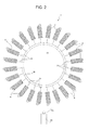
- Figure 2 diagrammatically shows the twenty-four conduits 4f, arranged as a crown about turbine 3, which is not shown for simplicity.
- each flexible conduit 4 (both 4f and 4g) comprises a first piping 10 with multiple metal walls comprising at least one bellows sleeve 11 and a second piping 12 arranged coaxially and radially external to piping 10, and radially spaced apart from piping 10, so as to define an empty tubular annular chamber 13 therein, between pipings 10 and 12.
- Piping 12 consists of: a flexible sleeve 14 made of a fire-retardant polymeric material, preferably of a low friction coefficient type, and delimited by a smooth outer lateral wall 15 which constitutes the outer lateral wall of the corresponding flexible conduit 4; and of a pair of stiff metal tubular hubs 17, in particular socket-like shaped, fixed onto respective smooth end stretches 18 of piping 10 and on which hubs opposite ends 19, 20 of the flexible sleeve 14 are fitted, substantially in a fluid tight manner.
- the fuel feeding system 1 also comprises at least one sensor 21, in particular one or more pressure sensors 21b, and/or one (or more) level sensor 21c; moreover, at least one of hubs 17 and preferably both, is/are laterally provided with a threaded mouth or nozzle 22 for connecting the empty annular chamber 13 with one sensor 21 so as to enable sensor 21 to detect fuel leaks from piping 10.
- both opposite tubular hubs 17 of piping 12 are each provided with a respective threaded mouth or nozzle 22; nozzle 22 optionally not connected with sensor 21 (like that shown on the right in figure 1 ) is fluid-sealed closed by a threaded cap 23.
- the opposite ends 19, 20 of the flexible sleeve 14 are simply fitted in contact onto respective overhangly projecting ends 24 of the tubular hubs 17, socket-like shaped, and are fixed onto the same by respective circumferential clamping metal annular bands 25 (of the type similar to those used in household systems).
- each tubular hub 17 is provided with an annular shallow shaping 16, preferably obtained by means of plastic deformation with diameter reduction of a lateral wall portion of end 24, defining a groove at which band 25 is mounted, which band thus sandwiches the corresponding end 19 or 20 of the flexible sleeve 14 against the tubular hub 17 end 24 so as to deform it and push an annular portion thereof within the groove or annular shallow shaping 26.
- each piping 12 is provided with a sensor 21 applied fluid-tightly mounted directly onto a threaded mouth or nozzle 22 in place of cap 23.
- all conduits 4g are provided with a pressure sensor 21b on one of the two threaded nozzles 22 thereof.
- Each sensor 21b is provided with optical signalling means 27, for example a LED light or lamp, which are arranged at the threaded mouth or nozzle 22 so as to be visible externally to the flexible conduit 4 and which therefore are directly arranged onto each same conduit 4g.
- sensors 21b are all connected, via a data transmission line 29, with an alarm unit 30, for example located in the control room of turbine 3.
- an alarm unit 30 for example located in the control room of turbine 3.
- each (of some) piping 12 may be fluid-tightly connected, rather than directly with a sensor 21, with a collecting pipe 31 which radially leads into a collecting manifold 32 for the fuel that may escape from piping 10; the collecting manifold 32 is provided with a tank 33, in turn provided with a sensor 21.
- the collecting manifold 32 is annular in shape and tank 33 is vertically arranged, in use, beneath the gas turbine 3, and is provided with a level sensor 21c, of mechanical or pneumatic type as well.
- a collecting pipe 31 branches off from a threaded mouth or nozzle 22 of the outer piping 12 of each conduit 4f which pipe leads into an annular manifold 32 for collecting the liquid fuel provided at the bottom with a tank 33 equipped with a single level sensor 21c in common to all conduits 4f; on the other hand, a threaded mouth or nozzle 22 of the outer piping 12 of each conduit 4g is provided with a pressure sensor 21b equipped with an optical signaller 27 outside conduit 4g.
- each piping 10 of each flexible conduit 4 comprises an internal liner defined by a first radially innermore cylindrical sleeve 34, formed by a crimped helical metal strip (however, this element is not strictly necessary), a second radially intermediate metal sleeve formed by the bellows sleeve 11, which ends with opposite smooth ends 35, and an external stainless steel braid defined by a third radially outermore metal sleeve 36 formed of a braided metal mesh and fitted in contact with the bellows sleeve 11, shown in an external view in figure 1 , at the bottom (beneath a symmetry axis A of conduit 4).
- the metal sleeves 34, 11 and 36 are integrally connected, in a known manner, at the opposite ends.
- the flexible sleeve 14 of piping 12 is, according to the invention, made of a silicone polymer which is fire-retardant or made fire-retardant by the addition of suitable additives.
- This material (or another one having equivalent technical features) surprisingly allows the underlying piping 10 to be protected from any "fretting fatigue” phenomenon in the operating conditions of turbine 3. Therefore, in the field of fuel feeding, in particular for turbo-gas plants, it is a completely innovative use of a sleeve made with such a material. Moreover, its combination with the stiff tubular hubs 17 provides the solution to the fuel leak problem.
Landscapes
- Engineering & Computer Science (AREA)
- General Engineering & Computer Science (AREA)
- Mechanical Engineering (AREA)
- Chemical & Material Sciences (AREA)
- Combustion & Propulsion (AREA)
- Physics & Mathematics (AREA)
- General Physics & Mathematics (AREA)
- Feeding And Controlling Fuel (AREA)
Abstract
Description
- The present invention relates to a high safety gas turbine burner fuel feeding system, in particular for gas turbines adapted to be fed with different fuels.
-
EP 1736651A describes a gas turbine burner fuel feeding system which uses controlled-flexibility flexible pipings; flexible pipings are made of a metal material with a multi-tubular structure consisting of multiple sleeves, among which a bellows sleeve, concentrically coupled to each other; a similar structure, although relating to another technical field and for piping lengths of a different order of magnitude (tenths centimeters against meters in the case of gas turbine burner feeding) is known fromEP-A-0681096 . - While the known fuel feeding system is fully satisfactory, it has the drawback that controlled-flexibility pipings can undergo undesired wear due to the "fretting fatigue" phenomenon, caused by the friction of the metal pipings with each other and with the turbine casing, which occurs both in the assembly/maintenance step and above all, due to the movements caused by the thermal and mechanical stresses received in use by such pipings.
- Another problem found in turbo-gas plant fuel feeding systems is represented by the risks related to possible fuel leaks from one or more burner feeding pipings, which is even more likely in the case of flexible pipings of the type in
EP 1736651A , due to the "fretting fatigue" phenomenon. - It should be noted that gas turbines of fixed plants for energy generation are usually enclosed, along with the burner fuel feeding system, in a fluid-sealed casing or enclosure, monitored by specific sensors capable of detecting the presence of volatile substances in the air present into the enclosure, and thus capable of detecting gas leaks, for example, in the case of methane-fed turbo-gas plants.
- However, on the one hand such systems are triggered with some delay as compared to the occurrence of the leak and on the other hand, they do not allow the piping from which the leak has occurred to be detected.
- In the case of gas oil (diesel)-fed gas turbines, the liquid fuel is fed under pressure to the burners, thus the occurrence of an even minimal crack in one of the gas oil feeding pipings produces an atomized jet of gas oil which is dispersed in the closed environment of the containment casing, thereby increasing the risk of fire to unacceptable levels.
-
US2003/0094207 describes a flexible conduit in which the risk of leaks is reduced, since the conduit consists of two flexible pipings mounted one inside the other fluid sealed-wise. Firstly, this solution relates to a totally different technical field, i.e. it is intended to be used in vehicle discharge systems where, among the other things, the "fretting fatigue" phenomenon does not exist and in the second place, it is intended to prevent burnt gas leaks to the atmosphere, in the case the inner piping breaks up. Such a solution, if applied as it is to fuel feeding systems like the one ofEP 1736651A , on the one hand does not seem adapted to the man skilled in the art to solve the "fretting fatigue" problem, which inUS2003/0094207 is not even mentioned, and which actually, in the application contemplated inUS2003/0094207 , as already mentioned, does not exist, and in the second place, even if it was capable of restraining any fuel leaks, it does not solve the problem of providing an early alarm of the breakage of the inner piping, nor that of preventing atomized gas leaks, since nobody would notice the breakage of the inner piping and, should also the outer piping break up, exactly the same technical problems to be solved would happen again. Moreover, implementing a dual gas-sealed piping as that described would increase the cost of the fuel feeding system in the turbo-gas field, in an undesired manner. - It is the object of the present invention to provide a gas turbine burner fuel feeding system which is fully compatible with the provisions of
EP 1736651A , but without being subject to "fretting fatigue" and which, at the same time, provides an early and punctual alarm of possible fuel leaks, totally preventing possible gas oil atomization to the atmosphere, as well. - It is also an object of the invention to provide such a fuel feeding system in which, with minimal waste, it is possible to immediately detect the damaged piping, in particular in the case of gaseous fuel, which fuel feeding system has small overall dimensions, is cheap and easy to be installed.
- According to the present invention, therefore, a burner fuel feeding system is provided, in particular for a gas turbine, according to
claim 1. - In particular, the fuel feeding system according to the invention comprises at least one flexible conduit connecting a fuel manifold to the burner and the flexible conduit comprises a first piping with multiple metal walls comprising at least one bellows sleeve and a second piping radially external to the first one, and radially spaced apart from the first piping, so as to define an empty annular chamber therein, between the first and the second piping.
- The second piping consists of a flexible sleeve made of a fire-retardant polymeric material and delimited by a smooth outer lateral wall which constitutes the outer lateral wall of the flexible conduit; and of a pair of stiff metal tubular hubs fixed onto respective smooth end stretches of the first piping and on which opposite ends of the flexible sleeve are fitted substantially fluid-tight manner; in combination, the fuel feeding system also comprises at least one pressure or level sensor and at least one of the hubs is laterally provided with threaded mouth or a nozzle for connecting the empty annular chamber with the sensor in such a manner so as to enable the sensor to detect fuel leaks from the first piping.
- Preferably, the feeding system provides for fluid-tightly fitting a pressure sensor directly onto a hub of the second piping of each flexible conduit and for providing the sensor with optical signalling means arranged at the threaded mouth or nozzle, so as to be visible externally to the flexible conduit and directly arranged onto the same conduit.
- Alternatively or in addition to such a solution, the mouth or nozzle is fluid-tightly connected to a pipe which radially leads into a collecting manifold for the fuel that may exit from the first piping; the collecting manifold is provided with a tank provided in turn with said sensor. Therefore, in the case a plurality of flexible conduits is provided, it is possible to connect all the conduits to a single collecting manifold, and thus use a single sensor, a particularly effective solution in the case of a liquid fuel, such as gas oil, where a simple level sensor may be used.
- Thereby, an early alarm can be obtained in all cases, since the sensor is triggered before the internal environment of the containment casing or enclosure of the turbine is saturated by volatile substances to such an extent as to trigger the alarm sensors already present in the prior art; moreover, by providing a sensor for each conduit, it is also possible to immediately know which piping has been damaged. Finally, by making the smooth surface flexible sleeve of the second piping of polymeric, preferably silicone, material, the "fretting fatigue" phenomenon it totally eliminated, ensuring a very high time-course duration and reliability of the fuel feeding system according to the finding.
- Moreover, above all, in the case of liquid fuels, the risk of leaks with forming of fuel "sprays" which are very dangerous for fire hazards, is completely prevented. In fact, the flexible sleeve blocks such a leak and the sensor gives the alarm well before the outermost piping may crack as well.
- Finally, it is apparent that the present invention may be applied to any pressurized fluid transport system, for quickly and safely detecting possible leaks while preventing sudden dispersions of the pressurized fluid.
- The invention therefore also relates to a pressurized fluid transport system according to
claim 12. - Further features of the present invention will appear clearly from the following description of a purely exemplary and non-limiting embodiment thereof, made with reference to the figures of the accompanying drawings, in which:
-
figure 1 shows an elevational, longitudinal sectional view of a construction detail of the fuel feeding system according to the finding; -
figure 2 shows a diagrammatic view of the fuel feeding system according to the invention in the case of a turbine provided with a plurality of burners arranged as a crown about the turbine; and -
figure 3 shows a partially diagrammatic and perspective three-fourth rear view of a gas turbine casing shown open and with parts removed for a better understanding, provided with the fuel feeding system according to the invention, shown at a burner arranged beneath the gas turbine. - With reference to
figures 1 to 3 ,reference numeral 1 denotes as a whole a fuel feeding system for aburner 2 of a gas turbine 3 comprising at least oneflexible conduit 4 connecting a fuel manifold 5 withburner 2. - While herein and hereinafter the fuel feeding system according to the invention is described with reference to a gas turbine, it is clear that it may be used in any application contemplating the transport of gaseous or liquid fuels, generally pressurized, along flexible pipings. More generally, the
fuel feeding system 1 may be configured as a transport system of a generic pressurized fluid, in the example shown consisting of a liquid or gaseous fuel, but which more generally may also consist of a not necessarily flammable fluid. - In the preferred embodiment, shown in
figure 3 , the gas turbine 3 is provided with a plurality ofburners 2, for example twenty-four (only one of which is shown for simplicity), which may be fed either with gaseous fuel, such as methane, or with liquid fuel, such as gas oil, arranged as a crown about atubular casing 6 of turbine 3, a part of which is visible infigure 3 . - The
feeding system 1 therefore comprises a first plurality of circular annular manifolds 5f1, 5f2 and 5f3 for the liquid fuel and a second plurality of circular annular manifolds 5g1, 5g2 and 5g3 for the gaseous fuel, each of which is provided with a plurality offlexible conduits 4f for the liquid fuel (manifolds 5f1, 2, 3) and 4g for the gaseous fuel (manifolds 5g1, 2, 3), which radially branch off as a crown from the annular manifolds 5f1, 2, 3 and 5g1, 2, 3, respectively, in a number of one for eachburner 2. - The circular annular manifolds 5f1, 2, 3 and 5g1, 2, 3 are all arranged concentric to one another and aligned at a single lying plane, crosswise turbine 3, arranged slanted in
figure 3 , and theflexible conduits figure 1 only shows one, denoted as a whole withreference numeral 4.Figure 2 diagrammatically shows the twenty-fourconduits 4f, arranged as a crown about turbine 3, which is not shown for simplicity. - According to a feature of the invention and with particular reference to
figure 1 , each flexible conduit 4 (both 4f and 4g) comprises afirst piping 10 with multiple metal walls comprising at least onebellows sleeve 11 and asecond piping 12 arranged coaxially and radially external to piping 10, and radially spaced apart frompiping 10, so as to define an empty tubularannular chamber 13 therein, betweenpipings -
Piping 12 consists of: aflexible sleeve 14 made of a fire-retardant polymeric material, preferably of a low friction coefficient type, and delimited by a smooth outerlateral wall 15 which constitutes the outer lateral wall of the correspondingflexible conduit 4; and of a pair of stiff metaltubular hubs 17, in particular socket-like shaped, fixed onto respective smooth end stretches 18 ofpiping 10 and on which hubs oppositeends flexible sleeve 14 are fitted, substantially in a fluid tight manner. - According to the invention, and in combination with the structure described thus far, the
fuel feeding system 1 also comprises at least one sensor 21, in particular one ormore pressure sensors 21b, and/or one (or more)level sensor 21c; moreover, at least one ofhubs 17 and preferably both, is/are laterally provided with a threaded mouth ornozzle 22 for connecting the emptyannular chamber 13 with one sensor 21 so as to enable sensor 21 to detect fuel leaks frompiping 10. - In the example shown, both opposite
tubular hubs 17 ofpiping 12 are each provided with a respective threaded mouth ornozzle 22;nozzle 22 optionally not connected with sensor 21 (like that shown on the right infigure 1 ) is fluid-sealed closed by a threadedcap 23. - Moreover, in order to implement the above-mentioned fluid-sealed coupling achieving likewise the object of limiting the construction costs of the
fuel feeding system 1, theopposite ends flexible sleeve 14 are simply fitted in contact onto respective overhangly projectingends 24 of thetubular hubs 17, socket-like shaped, and are fixed onto the same by respective circumferential clamping metal annular bands 25 (of the type similar to those used in household systems). In particular,end 24 of eachtubular hub 17 is provided with an annularshallow shaping 16, preferably obtained by means of plastic deformation with diameter reduction of a lateral wall portion ofend 24, defining a groove at whichband 25 is mounted, which band thus sandwiches thecorresponding end flexible sleeve 14 against thetubular hub 17end 24 so as to deform it and push an annular portion thereof within the groove or annularshallow shaping 26. - Thereby, a simple and cost-effective connection of
sleeve 14 withhubs 17 is obtained which creates both a pressure- and a labyrinth- seal which is totally effective both against liquids and also against possible gases, which prevents the escape fromchamber 13 of any type of fuel that may have entered therein, at least for a certain time.Hubs 17 are then circumferentially welded to stretches 18, thus integrally and fluid-tightly connectingpiping 12 to piping 10. Theflexible conduit 4 thus formed is also provided with connectingends 26, only one of which is shown infigure 1 ,conduit 4 being shown truncated, for the fluid-sealed connection to manifolds 5. Ends 26 may be flanged, as in the example shown, or simply threaded. - As shown in
figure 1 , eachpiping 12 is provided with a sensor 21 applied fluid-tightly mounted directly onto a threaded mouth ornozzle 22 in place ofcap 23. In the preferred embodiment of the invention, allconduits 4g are provided with apressure sensor 21b on one of the two threadednozzles 22 thereof. Eachsensor 21b is provided with optical signalling means 27, for example a LED light or lamp, which are arranged at the threaded mouth ornozzle 22 so as to be visible externally to theflexible conduit 4 and which therefore are directly arranged onto eachsame conduit 4g. - Thereby, and thanks to the above-described connection system between
ends hubs 17, in the case of a methane leak from one ofpipings 10, the pressure intochamber 13 rises immediately, thus activatingsensor 21b andalarm light 27. An operator can thus immediately identify the damagedconduit 4g at a glance, even standing outside a containment casing (enclosure) 28 of turbine 3 (only diagrammatically shown infigure 3 ), for example through a window of the same, or in any case he/she can identify the leaking tube during an inspection on the gas turbine, entering intocasing 28, since there are no leaks to the outside yet. - Moreover,
sensors 21b are all connected, via adata transmission line 29, with analarm unit 30, for example located in the control room of turbine 3. Thereby, an early leak alarm is obtained well before the presence of gas is detected insidecasing 28 by the normally supplied gas sensors. - The same thing may happen in the case of a gas oil leak, further preventing the atomization of the same: in fact, even if under pressure, gas oil collects into
chamber 13 without crossingsleeve 14. - As shown in
figures 2 and3 , as an alternative or in combination with what described above, the threaded mouths ornozzles 22 of each (of some)piping 12 may be fluid-tightly connected, rather than directly with a sensor 21, with acollecting pipe 31 which radially leads into acollecting manifold 32 for the fuel that may escape frompiping 10; thecollecting manifold 32 is provided with atank 33, in turn provided with a sensor 21. - If the fuel is a liquid fuel, the
collecting manifold 32 is annular in shape andtank 33 is vertically arranged, in use, beneath the gas turbine 3, and is provided with alevel sensor 21c, of mechanical or pneumatic type as well. - In the example shown (
figure 3 ), acollecting pipe 31 branches off from a threaded mouth ornozzle 22 of theouter piping 12 of eachconduit 4f which pipe leads into anannular manifold 32 for collecting the liquid fuel provided at the bottom with atank 33 equipped with asingle level sensor 21c in common to allconduits 4f; on the other hand, a threaded mouth ornozzle 22 of theouter piping 12 of eachconduit 4g is provided with apressure sensor 21b equipped with anoptical signaller 27outside conduit 4g. - In order to ensure the required sturdiness, reliability and controlled flexibility, each
piping 10 of eachflexible conduit 4 comprises an internal liner defined by a first radially innermorecylindrical sleeve 34, formed by a crimped helical metal strip (however, this element is not strictly necessary), a second radially intermediate metal sleeve formed by thebellows sleeve 11, which ends with oppositesmooth ends 35, and an external stainless steel braid defined by a third radiallyoutermore metal sleeve 36 formed of a braided metal mesh and fitted in contact with thebellows sleeve 11, shown in an external view infigure 1 , at the bottom (beneath a symmetry axis A of conduit 4). - The
metal sleeves flexible sleeve 14 ofpiping 12 is, according to the invention, made of a silicone polymer which is fire-retardant or made fire-retardant by the addition of suitable additives. - This material (or another one having equivalent technical features) surprisingly allows the
underlying piping 10 to be protected from any "fretting fatigue" phenomenon in the operating conditions of turbine 3. Therefore, in the field of fuel feeding, in particular for turbo-gas plants, it is a completely innovative use of a sleeve made with such a material. Moreover, its combination with the stifftubular hubs 17 provides the solution to the fuel leak problem.
Claims (12)
- A fuel feeding system (1), in particular for a burner (2) of a gas turbine (3), comprising at least one flexible conduit (4), in particular connecting a fuel manifold (5) to the burner; wherein the flexible conduit comprises a first piping (10) with multiple metal walls comprising at least one bellows sleeve (11) and a second piping (12) radially external to the first one, and radially spaced apart from the first piping, so as to define an empty annular chamber (13) therein, between the first and the second piping (13); characterised in that the second piping (12) consists of: a flexible sleeve (14) made of a fire-retardant polymeric material and delimited by a smooth outer lateral wall (15) that constitutes the outer lateral wall of the flexible conduit; and of a pair of stiff metal tubular hubs (17) fixed onto respective smooth end stretches (18) of the first piping and on which hubs opposite ends (19, 20) of the flexible sleeve (14) are fitted in a substantially fluid-tight manner; and in that in combination, the fuel feeding system comprises at least one pressure (21b) or level (21c) sensor; at least one of the hubs being laterally provided with a threaded mouth or a nozzle (22) for connecting the empty annular chamber (13) to the sensor (21) in such a manner so as to enable the sensor to detect fuel leaks from the first piping.
- A fuel feeding system according to claim 1, characterized in that the sensor is a pressure sensor (21b) directly fluid-tight mounted onto said mouth (22).
- A fuel feeding system according to claim 2, characterized in that said sensor (21b) is provided with optical signalling means (27) which are arranged at said threaded nozzle or inlet so as to be visible externally to the flexible conduit (4) and are directly arranged onto the same conduit.
- A fuel feeding system according to one of the preceding claims, characterized in that said threaded mouth or nozzle (22) is fluid-tightly connected to a collecting pipe (31) which radially leads into a collecting manifold (32) for the fuel that may exit from the first piping, the collecting manifold being provided, in particular if the fuel is a liquid fuel, with a tank (33) provided in turn with said sensor (21).
- A fuel feeding system according to claim 4, wherein the gas turbine is provided with a plurality of burners (2), arranged as a crown about the same, characterized in that the fuel manifold (5) is annular and in that it comprises a plurality of said flexible conduits (4) which branch off as a crown from said annular manifold, in a number of at least one per each burner, where if the fuel is a liquid fuel, the collecting manifold (32) is annular as well and the tank (33) is vertically arranged and in use underneath the gas turbine, and is provided with a level sensor (21c).
- A fuel feeding system according to one of the preceding claims, characterized in that the sensor (21) is connected with an alarm unit (30) via a data transmission line (29).
- A fuel feeding system according to one of the preceding claims, characterized in that both opposite tubular hubs (17) of the second piping are each provided with a respective said threaded mouth or nozzle (22); the threaded mouth or nozzle possibly not connected to a sensor being fluid-tightly closed by means of a threaded cap (23).
- A fuel feeding system according to one of the preceding claims, characterized in that said opposite ends (19, 20) of the flexible sleeve are simply fitted in contact onto respective overhangly projecting ends (24) of the tubular hubs, integrally obtained therewith, and are fixed onto the same by respective circumferential clamping annular metal bands (25).
- A fuel feeding system according to claim 8, characterized in that said ends of the tubular hubs are each provided with an annular shallow shaping (26) defining an annular groove, preferably obtained by means of plastic deformation of an outer wall portion of the end (24) of the tubular sleeve, at which shallow shaping said band (25) is mounted, the band sandwiching the corresponding end (19, 20) of the flexible sleeve against the tubular hub end so as to deform it and push an annular portion thereof within said shallow shaping (26).
- A fuel feeding system according to one of the preceding claims, wherein the gas turbine (3) is provided with a plurality of burners which may be fed with either gaseous fuel or liquid fuel, arranged as a crown about the same, characterized in that it comprises a first plurality of circular annular manifolds (5f1, 2, 3) for a liquid fuel, each of which is provided with a plurality of first flexible conduits (4f) which branch off as a crown from said annular manifold, in a number of one per each burner, a pipe (31) branching off from a mouth (22) of the second piping of each one of them, which pipe leads into an annular manifold (32) for collecting the liquid fuel provided at the bottom with a tank (33) equipped with a single level sensor (21c) in common to all the first conduits (4f); and in that it comprises a second plurality of circular annular manifolds (5g1, 2, 3) for a gaseous fuel, each of which is provided with a plurality of second flexible conduits (4g) which branch off as a crown from said annular manifold, in a number of one per each burner, a mouth (22) of the second piping of each one of them is provided with said pressure sensor (21b) equipped with an optical signaller (27) outside the piping; the circular annular manifolds (5) being all arranged concentric to one another and aligned at a single lying plane, crosswise the turbine, and the first and second flexible conduits (4f, 4g) being all equal to one another for each feeding line defined by a manifold and by the respective conduits.
- A fuel feeding system according to one of the preceding claims, characterized in that each said first piping (10) of each said flexible conduit optionally comprises an internal liner defining a first radially innermore cylindrical sleeve (34) formed by a crimped helical metal strip, a second radially intermediate metal sleeve, formed by said bellows sleeve (11), which ends with opposite smooth ends (35) and an external stainless steel braid defining a third radially outermore metal sleeve (36), formed of a braided metal mesh and fitted in contact with the bellows sleeve (11), the first, second and third metal sleeve being integrally jointed at the opposite ends; said flexible sleeve (14) of the second piping being made, on the other hand, of a silicon polymer.
- A pressurized fluid transport system comprising at least one flexible conduit (4), in particular connecting a fuel manifold (5) to the burner; wherein the flexible conduit comprises a first piping (10) with multiple metal walls comprising at least one bellows sleeve (11) and a second piping (12) radially external to the first one, and radially spaced apart from the first piping, so as to define an empty annular chamber (13) therein, between the first and the second piping (13); characterised in that the second piping (12) consists of: a flexible sleeve (14) made of a fire-retardant polymeric material and delimited by a smooth outer lateral wall (15) that constitutes the outer lateral wall of the flexible conduit; and of a pair of stiff metal tubular hubs (17) fixed onto respective smooth end stretches (18) of the first piping and on which hubs opposite ends (19, 20) of the flexible sleeve (14) are fitted, in a substantially fluid tight manner; and in that in combination, the pressurized fluid transport system comprises at least one pressure (21b) or level (21c) sensor; at least one of the hubs being laterally provided with a threaded mouth or a nozzle (22) for connecting the empty annular chamber (13) with the sensor (21) so as to enable the sensor to detect pressurized fluid leaks from the first piping.
Applications Claiming Priority (1)
| Application Number | Priority Date | Filing Date | Title |
|---|---|---|---|
| IT000190A ITTO20120190A1 (en) | 2012-03-02 | 2012-03-02 | HIGH SAFETY FUEL SUPPLY SYSTEM FOR A GAS TURBINE BURNER |
Publications (2)
| Publication Number | Publication Date |
|---|---|
| EP2634380A1 true EP2634380A1 (en) | 2013-09-04 |
| EP2634380B1 EP2634380B1 (en) | 2014-10-29 |
Family
ID=46548717
Family Applications (1)
| Application Number | Title | Priority Date | Filing Date |
|---|---|---|---|
| EP13157699.3A Active EP2634380B1 (en) | 2012-03-02 | 2013-03-04 | Gas turbine burner fuel feeding system |
Country Status (3)
| Country | Link |
|---|---|
| EP (1) | EP2634380B1 (en) |
| ES (1) | ES2523986T3 (en) |
| IT (1) | ITTO20120190A1 (en) |
Cited By (10)
| Publication number | Priority date | Publication date | Assignee | Title |
|---|---|---|---|---|
| GB2509304A (en) * | 2012-11-07 | 2014-07-02 | Stuart Grant Jones | Fabricating, Pressure Testing and Monitoring a Double Layer Hose Assembly |
| EP2865867A1 (en) * | 2013-10-28 | 2015-04-29 | Delavan Inc. | Enhanced fire protection for fuel manifold |
| CN106322050A (en) * | 2015-06-19 | 2017-01-11 | 宝山钢铁股份有限公司 | Leakproof device of connecting part |
| CN106439369A (en) * | 2016-11-17 | 2017-02-22 | 大连捷瑞流体控制股份有限公司 | Hose assembly system with failure detection function |
| CN108278437A (en) * | 2018-04-04 | 2018-07-13 | 南京知行管业有限公司 | A kind of intelligent gas pipeline compensator |
| EP3719276A1 (en) * | 2019-04-03 | 2020-10-07 | Rolls-Royce plc | Oil pipe assembly |
| EP3719471A1 (en) * | 2019-04-03 | 2020-10-07 | Daspos A/S | A leakage detector system |
| US20220397479A1 (en) * | 2021-06-09 | 2022-12-15 | Pratt & Whitney Canada Corp. | Leak detection for pressurized fluid systems |
| FR3142224A1 (en) * | 2022-11-21 | 2024-05-24 | Safran | COMBUSTIBLE FLUID SUPPLY SYSTEM FOR A COMBUSTION CHAMBER |
| FR3142225A1 (en) * | 2022-11-21 | 2024-05-24 | Safran | COMBUSTIBLE FLUID SUPPLY SYSTEM FOR A COMBUSTION CHAMBER |
Citations (7)
| Publication number | Priority date | Publication date | Assignee | Title |
|---|---|---|---|---|
| EP0681096A1 (en) | 1994-05-05 | 1995-11-08 | Witzenmann GmbH Metallschlauch-Fabrik Pforzheim | Flexible pipe component for exhaust conduits of internal combustion engines used on vehicles |
| JPH08261861A (en) * | 1995-03-27 | 1996-10-11 | Mitsubishi Heavy Ind Ltd | Flexible tube for oil pipe |
| EP0874185A1 (en) * | 1997-04-24 | 1998-10-28 | Klenk GmbH | Hose, in particular for fuel dispenser |
| US6082392A (en) * | 1997-09-30 | 2000-07-04 | General Transervice, Inc. | Dual hose assembly and control system for truck-to-truck fuel transfer |
| US20030094207A1 (en) | 2001-11-20 | 2003-05-22 | Abe Qutub | Leak-free flexible conduit |
| EP1736651A2 (en) | 2005-06-23 | 2006-12-27 | Ansaldo Energia S.P.A. | Gas turbine burner fuel feeding system |
| US8079220B2 (en) * | 2008-08-28 | 2011-12-20 | Delavan Inc | Fuel distribution manifold system for gas turbine engines |
-
2012
- 2012-03-02 IT IT000190A patent/ITTO20120190A1/en unknown
-
2013
- 2013-03-04 EP EP13157699.3A patent/EP2634380B1/en active Active
- 2013-03-04 ES ES13157699.3T patent/ES2523986T3/en active Active
Patent Citations (7)
| Publication number | Priority date | Publication date | Assignee | Title |
|---|---|---|---|---|
| EP0681096A1 (en) | 1994-05-05 | 1995-11-08 | Witzenmann GmbH Metallschlauch-Fabrik Pforzheim | Flexible pipe component for exhaust conduits of internal combustion engines used on vehicles |
| JPH08261861A (en) * | 1995-03-27 | 1996-10-11 | Mitsubishi Heavy Ind Ltd | Flexible tube for oil pipe |
| EP0874185A1 (en) * | 1997-04-24 | 1998-10-28 | Klenk GmbH | Hose, in particular for fuel dispenser |
| US6082392A (en) * | 1997-09-30 | 2000-07-04 | General Transervice, Inc. | Dual hose assembly and control system for truck-to-truck fuel transfer |
| US20030094207A1 (en) | 2001-11-20 | 2003-05-22 | Abe Qutub | Leak-free flexible conduit |
| EP1736651A2 (en) | 2005-06-23 | 2006-12-27 | Ansaldo Energia S.P.A. | Gas turbine burner fuel feeding system |
| US8079220B2 (en) * | 2008-08-28 | 2011-12-20 | Delavan Inc | Fuel distribution manifold system for gas turbine engines |
Cited By (17)
| Publication number | Priority date | Publication date | Assignee | Title |
|---|---|---|---|---|
| GB2509304A (en) * | 2012-11-07 | 2014-07-02 | Stuart Grant Jones | Fabricating, Pressure Testing and Monitoring a Double Layer Hose Assembly |
| GB2509304B (en) * | 2012-11-07 | 2020-05-20 | Grant Jones Stuart | Fabricating, pressure testing & monitoring a double layer hose assembly |
| EP2865867A1 (en) * | 2013-10-28 | 2015-04-29 | Delavan Inc. | Enhanced fire protection for fuel manifold |
| CN106322050A (en) * | 2015-06-19 | 2017-01-11 | 宝山钢铁股份有限公司 | Leakproof device of connecting part |
| CN106439369A (en) * | 2016-11-17 | 2017-02-22 | 大连捷瑞流体控制股份有限公司 | Hose assembly system with failure detection function |
| CN106439369B (en) * | 2016-11-17 | 2019-04-26 | 大连捷瑞流体控制股份有限公司 | Hose assembly system with failure detection |
| CN108278437A (en) * | 2018-04-04 | 2018-07-13 | 南京知行管业有限公司 | A kind of intelligent gas pipeline compensator |
| EP3719471A1 (en) * | 2019-04-03 | 2020-10-07 | Daspos A/S | A leakage detector system |
| EP3719276A1 (en) * | 2019-04-03 | 2020-10-07 | Rolls-Royce plc | Oil pipe assembly |
| CN111795134A (en) * | 2019-04-03 | 2020-10-20 | 劳斯莱斯有限公司 | Oil pipe assembly |
| US11519297B2 (en) | 2019-04-03 | 2022-12-06 | Rolls-Royce Plc | Oil pipe assembly |
| CN111795134B (en) * | 2019-04-03 | 2023-06-06 | 劳斯莱斯有限公司 | Oil pipe assembly |
| US20220397479A1 (en) * | 2021-06-09 | 2022-12-15 | Pratt & Whitney Canada Corp. | Leak detection for pressurized fluid systems |
| US11846568B2 (en) * | 2021-06-09 | 2023-12-19 | Pratt & Whitney Canada Corp. | Leak detection for pressurized fluid systems |
| FR3142224A1 (en) * | 2022-11-21 | 2024-05-24 | Safran | COMBUSTIBLE FLUID SUPPLY SYSTEM FOR A COMBUSTION CHAMBER |
| FR3142225A1 (en) * | 2022-11-21 | 2024-05-24 | Safran | COMBUSTIBLE FLUID SUPPLY SYSTEM FOR A COMBUSTION CHAMBER |
| WO2024110721A1 (en) | 2022-11-21 | 2024-05-30 | Safran | System for supplying fluid fuel to a combustion chamber |
Also Published As
| Publication number | Publication date |
|---|---|
| ITTO20120190A1 (en) | 2013-09-03 |
| EP2634380B1 (en) | 2014-10-29 |
| ES2523986T3 (en) | 2014-12-03 |
Similar Documents
| Publication | Publication Date | Title |
|---|---|---|
| EP2634380B1 (en) | Gas turbine burner fuel feeding system | |
| US6029505A (en) | Connecting device for pipe assemblies | |
| US5927762A (en) | Pipe coupling assembly system and method | |
| US5713607A (en) | Pipe coupling assembly, system and method | |
| RU2652856C9 (en) | Fitting for use with metal tubing | |
| US20090173393A1 (en) | Pressure relief device | |
| CN218582919U (en) | Prevent leaking pipeline structure | |
| WO2022263810A1 (en) | A method of manufacturing a double-walled elbow pipe segment, a pipe assembly | |
| CN220082856U (en) | Gas pipeline leakage alarm device | |
| EP4328476A1 (en) | Improved coupling for double-walled hoses | |
| CN202637773U (en) | Automatic steam fire-fighting apparatus used for high temperature flange | |
| NO330645B1 (en) | high pressure safety hose | |
| JP2016020729A (en) | Piping joint cover, piping joint cover mounting method, and fluid scattering prevention device for piping joint section | |
| US2930031A (en) | Excess pressure indicator and safety control circuit therefor | |
| CN104080518A (en) | Safety assembly for containers and conduits for combustible fluids | |
| US9546752B2 (en) | Device for detecting and isolating fuel leaks in a vehicle | |
| AU2020294087B2 (en) | Apparatus, system and method for maintenance of a structure carrying a fluid | |
| KR20240072419A (en) | System for detecting leak of hazardous chemical from pipe connection | |
| CN108869821A (en) | Pressure relief device for oil field pressure medium | |
| CN210034621U (en) | Prevent natural gas valve of leakage | |
| US7104727B1 (en) | Piping system with transition coupling | |
| CN209587488U (en) | A kind of danger medium conveyance conduit | |
| CN208311689U (en) | A kind of metal hose of anti-leak early warning | |
| RU2315192C2 (en) | Safety device for washing system of liquid fuel injectors used in gas turbines | |
| CN119665034B (en) | Pipeline connection protection device |
Legal Events
| Date | Code | Title | Description |
|---|---|---|---|
| PUAI | Public reference made under article 153(3) epc to a published international application that has entered the european phase |
Free format text: ORIGINAL CODE: 0009012 |
|
| AK | Designated contracting states |
Kind code of ref document: A1 Designated state(s): AL AT BE BG CH CY CZ DE DK EE ES FI FR GB GR HR HU IE IS IT LI LT LU LV MC MK MT NL NO PL PT RO RS SE SI SK SM TR |
|
| AX | Request for extension of the european patent |
Extension state: BA ME |
|
| 17P | Request for examination filed |
Effective date: 20140304 |
|
| RBV | Designated contracting states (corrected) |
Designated state(s): AL AT BE BG CH CY CZ DE DK EE ES FI FR GB GR HR HU IE IS IT LI LT LU LV MC MK MT NL NO PL PT RO RS SE SI SK SM TR |
|
| GRAP | Despatch of communication of intention to grant a patent |
Free format text: ORIGINAL CODE: EPIDOSNIGR1 |
|
| INTG | Intention to grant announced |
Effective date: 20140516 |
|
| GRAS | Grant fee paid |
Free format text: ORIGINAL CODE: EPIDOSNIGR3 |
|
| GRAA | (expected) grant |
Free format text: ORIGINAL CODE: 0009210 |
|
| AK | Designated contracting states |
Kind code of ref document: B1 Designated state(s): AL AT BE BG CH CY CZ DE DK EE ES FI FR GB GR HR HU IE IS IT LI LT LU LV MC MK MT NL NO PL PT RO RS SE SI SK SM TR |
|
| REG | Reference to a national code |
Ref country code: GB Ref legal event code: FG4D |
|
| REG | Reference to a national code |
Ref country code: CH Ref legal event code: EP |
|
| REG | Reference to a national code |
Ref country code: AT Ref legal event code: REF Ref document number: 693724 Country of ref document: AT Kind code of ref document: T Effective date: 20141115 |
|
| REG | Reference to a national code |
Ref country code: IE Ref legal event code: FG4D |
|
| REG | Reference to a national code |
Ref country code: ES Ref legal event code: FG2A Ref document number: 2523986 Country of ref document: ES Kind code of ref document: T3 Effective date: 20141203 |
|
| REG | Reference to a national code |
Ref country code: DE Ref legal event code: R096 Ref document number: 602013000393 Country of ref document: DE Effective date: 20141211 |
|
| REG | Reference to a national code |
Ref country code: AT Ref legal event code: MK05 Ref document number: 693724 Country of ref document: AT Kind code of ref document: T Effective date: 20141029 |
|
| REG | Reference to a national code |
Ref country code: NL Ref legal event code: VDEP Effective date: 20141029 |
|
| REG | Reference to a national code |
Ref country code: LT Ref legal event code: MG4D |
|
| PG25 | Lapsed in a contracting state [announced via postgrant information from national office to epo] |
Ref country code: LT Free format text: LAPSE BECAUSE OF FAILURE TO SUBMIT A TRANSLATION OF THE DESCRIPTION OR TO PAY THE FEE WITHIN THE PRESCRIBED TIME-LIMIT Effective date: 20141029 Ref country code: PT Free format text: LAPSE BECAUSE OF FAILURE TO SUBMIT A TRANSLATION OF THE DESCRIPTION OR TO PAY THE FEE WITHIN THE PRESCRIBED TIME-LIMIT Effective date: 20150302 Ref country code: FI Free format text: LAPSE BECAUSE OF FAILURE TO SUBMIT A TRANSLATION OF THE DESCRIPTION OR TO PAY THE FEE WITHIN THE PRESCRIBED TIME-LIMIT Effective date: 20141029 Ref country code: NO Free format text: LAPSE BECAUSE OF FAILURE TO SUBMIT A TRANSLATION OF THE DESCRIPTION OR TO PAY THE FEE WITHIN THE PRESCRIBED TIME-LIMIT Effective date: 20150129 Ref country code: NL Free format text: LAPSE BECAUSE OF FAILURE TO SUBMIT A TRANSLATION OF THE DESCRIPTION OR TO PAY THE FEE WITHIN THE PRESCRIBED TIME-LIMIT Effective date: 20141029 Ref country code: IS Free format text: LAPSE BECAUSE OF FAILURE TO SUBMIT A TRANSLATION OF THE DESCRIPTION OR TO PAY THE FEE WITHIN THE PRESCRIBED TIME-LIMIT Effective date: 20150228 |
|
| PG25 | Lapsed in a contracting state [announced via postgrant information from national office to epo] |
Ref country code: CY Free format text: LAPSE BECAUSE OF FAILURE TO SUBMIT A TRANSLATION OF THE DESCRIPTION OR TO PAY THE FEE WITHIN THE PRESCRIBED TIME-LIMIT Effective date: 20141029 Ref country code: RS Free format text: LAPSE BECAUSE OF FAILURE TO SUBMIT A TRANSLATION OF THE DESCRIPTION OR TO PAY THE FEE WITHIN THE PRESCRIBED TIME-LIMIT Effective date: 20141029 Ref country code: HR Free format text: LAPSE BECAUSE OF FAILURE TO SUBMIT A TRANSLATION OF THE DESCRIPTION OR TO PAY THE FEE WITHIN THE PRESCRIBED TIME-LIMIT Effective date: 20141029 Ref country code: SE Free format text: LAPSE BECAUSE OF FAILURE TO SUBMIT A TRANSLATION OF THE DESCRIPTION OR TO PAY THE FEE WITHIN THE PRESCRIBED TIME-LIMIT Effective date: 20141029 Ref country code: PL Free format text: LAPSE BECAUSE OF FAILURE TO SUBMIT A TRANSLATION OF THE DESCRIPTION OR TO PAY THE FEE WITHIN THE PRESCRIBED TIME-LIMIT Effective date: 20141029 Ref country code: AT Free format text: LAPSE BECAUSE OF FAILURE TO SUBMIT A TRANSLATION OF THE DESCRIPTION OR TO PAY THE FEE WITHIN THE PRESCRIBED TIME-LIMIT Effective date: 20141029 Ref country code: GR Free format text: LAPSE BECAUSE OF FAILURE TO SUBMIT A TRANSLATION OF THE DESCRIPTION OR TO PAY THE FEE WITHIN THE PRESCRIBED TIME-LIMIT Effective date: 20150130 Ref country code: LV Free format text: LAPSE BECAUSE OF FAILURE TO SUBMIT A TRANSLATION OF THE DESCRIPTION OR TO PAY THE FEE WITHIN THE PRESCRIBED TIME-LIMIT Effective date: 20141029 |
|
| REG | Reference to a national code |
Ref country code: DE Ref legal event code: R097 Ref document number: 602013000393 Country of ref document: DE |
|
| PG25 | Lapsed in a contracting state [announced via postgrant information from national office to epo] |
Ref country code: EE Free format text: LAPSE BECAUSE OF FAILURE TO SUBMIT A TRANSLATION OF THE DESCRIPTION OR TO PAY THE FEE WITHIN THE PRESCRIBED TIME-LIMIT Effective date: 20141029 Ref country code: SK Free format text: LAPSE BECAUSE OF FAILURE TO SUBMIT A TRANSLATION OF THE DESCRIPTION OR TO PAY THE FEE WITHIN THE PRESCRIBED TIME-LIMIT Effective date: 20141029 Ref country code: CZ Free format text: LAPSE BECAUSE OF FAILURE TO SUBMIT A TRANSLATION OF THE DESCRIPTION OR TO PAY THE FEE WITHIN THE PRESCRIBED TIME-LIMIT Effective date: 20141029 Ref country code: RO Free format text: LAPSE BECAUSE OF FAILURE TO SUBMIT A TRANSLATION OF THE DESCRIPTION OR TO PAY THE FEE WITHIN THE PRESCRIBED TIME-LIMIT Effective date: 20141029 Ref country code: DK Free format text: LAPSE BECAUSE OF FAILURE TO SUBMIT A TRANSLATION OF THE DESCRIPTION OR TO PAY THE FEE WITHIN THE PRESCRIBED TIME-LIMIT Effective date: 20141029 |
|
| REG | Reference to a national code |
Ref country code: HU Ref legal event code: AG4A Ref document number: E023770 Country of ref document: HU |
|
| PG25 | Lapsed in a contracting state [announced via postgrant information from national office to epo] |
Ref country code: IT Free format text: LAPSE BECAUSE OF FAILURE TO SUBMIT A TRANSLATION OF THE DESCRIPTION OR TO PAY THE FEE WITHIN THE PRESCRIBED TIME-LIMIT Effective date: 20141029 |
|
| PLBE | No opposition filed within time limit |
Free format text: ORIGINAL CODE: 0009261 |
|
| STAA | Information on the status of an ep patent application or granted ep patent |
Free format text: STATUS: NO OPPOSITION FILED WITHIN TIME LIMIT |
|
| 26N | No opposition filed |
Effective date: 20150730 |
|
| REG | Reference to a national code |
Ref country code: HU Ref legal event code: HC9C |
|
| PG25 | Lapsed in a contracting state [announced via postgrant information from national office to epo] |
Ref country code: LU Free format text: LAPSE BECAUSE OF FAILURE TO SUBMIT A TRANSLATION OF THE DESCRIPTION OR TO PAY THE FEE WITHIN THE PRESCRIBED TIME-LIMIT Effective date: 20150304 Ref country code: MC Free format text: LAPSE BECAUSE OF FAILURE TO SUBMIT A TRANSLATION OF THE DESCRIPTION OR TO PAY THE FEE WITHIN THE PRESCRIBED TIME-LIMIT Effective date: 20141029 |
|
| REG | Reference to a national code |
Ref country code: IE Ref legal event code: MM4A |
|
| PG25 | Lapsed in a contracting state [announced via postgrant information from national office to epo] |
Ref country code: IE Free format text: LAPSE BECAUSE OF NON-PAYMENT OF DUE FEES Effective date: 20150304 |
|
| PG25 | Lapsed in a contracting state [announced via postgrant information from national office to epo] |
Ref country code: SI Free format text: LAPSE BECAUSE OF FAILURE TO SUBMIT A TRANSLATION OF THE DESCRIPTION OR TO PAY THE FEE WITHIN THE PRESCRIBED TIME-LIMIT Effective date: 20141029 |
|
| REG | Reference to a national code |
Ref country code: FR Ref legal event code: PLFP Year of fee payment: 4 |
|
| REG | Reference to a national code |
Ref country code: CH Ref legal event code: PL |
|
| PG25 | Lapsed in a contracting state [announced via postgrant information from national office to epo] |
Ref country code: MT Free format text: LAPSE BECAUSE OF FAILURE TO SUBMIT A TRANSLATION OF THE DESCRIPTION OR TO PAY THE FEE WITHIN THE PRESCRIBED TIME-LIMIT Effective date: 20141029 |
|
| PG25 | Lapsed in a contracting state [announced via postgrant information from national office to epo] |
Ref country code: CH Free format text: LAPSE BECAUSE OF NON-PAYMENT OF DUE FEES Effective date: 20160331 Ref country code: LI Free format text: LAPSE BECAUSE OF NON-PAYMENT OF DUE FEES Effective date: 20160331 |
|
| REG | Reference to a national code |
Ref country code: FR Ref legal event code: PLFP Year of fee payment: 5 |
|
| PG25 | Lapsed in a contracting state [announced via postgrant information from national office to epo] |
Ref country code: BG Free format text: LAPSE BECAUSE OF FAILURE TO SUBMIT A TRANSLATION OF THE DESCRIPTION OR TO PAY THE FEE WITHIN THE PRESCRIBED TIME-LIMIT Effective date: 20141029 |
|
| PG25 | Lapsed in a contracting state [announced via postgrant information from national office to epo] |
Ref country code: TR Free format text: LAPSE BECAUSE OF FAILURE TO SUBMIT A TRANSLATION OF THE DESCRIPTION OR TO PAY THE FEE WITHIN THE PRESCRIBED TIME-LIMIT Effective date: 20141029 |
|
| GBPC | Gb: european patent ceased through non-payment of renewal fee |
Effective date: 20170304 |
|
| PG25 | Lapsed in a contracting state [announced via postgrant information from national office to epo] |
Ref country code: GB Free format text: LAPSE BECAUSE OF NON-PAYMENT OF DUE FEES Effective date: 20170304 |
|
| REG | Reference to a national code |
Ref country code: FR Ref legal event code: PLFP Year of fee payment: 6 |
|
| PG25 | Lapsed in a contracting state [announced via postgrant information from national office to epo] |
Ref country code: SM Free format text: LAPSE BECAUSE OF FAILURE TO SUBMIT A TRANSLATION OF THE DESCRIPTION OR TO PAY THE FEE WITHIN THE PRESCRIBED TIME-LIMIT Effective date: 20141029 |
|
| PG25 | Lapsed in a contracting state [announced via postgrant information from national office to epo] |
Ref country code: MK Free format text: LAPSE BECAUSE OF FAILURE TO SUBMIT A TRANSLATION OF THE DESCRIPTION OR TO PAY THE FEE WITHIN THE PRESCRIBED TIME-LIMIT Effective date: 20141029 |
|
| PG25 | Lapsed in a contracting state [announced via postgrant information from national office to epo] |
Ref country code: AL Free format text: LAPSE BECAUSE OF FAILURE TO SUBMIT A TRANSLATION OF THE DESCRIPTION OR TO PAY THE FEE WITHIN THE PRESCRIBED TIME-LIMIT Effective date: 20141029 |
|
| PGFP | Annual fee paid to national office [announced via postgrant information from national office to epo] |
Ref country code: HU Payment date: 20220318 Year of fee payment: 10 |
|
| PGFP | Annual fee paid to national office [announced via postgrant information from national office to epo] |
Ref country code: BE Payment date: 20220321 Year of fee payment: 10 |
|
| PGFP | Annual fee paid to national office [announced via postgrant information from national office to epo] |
Ref country code: ES Payment date: 20220527 Year of fee payment: 10 |
|
| REG | Reference to a national code |
Ref country code: BE Ref legal event code: MM Effective date: 20230331 |
|
| PG25 | Lapsed in a contracting state [announced via postgrant information from national office to epo] |
Ref country code: HU Free format text: LAPSE BECAUSE OF NON-PAYMENT OF DUE FEES Effective date: 20230305 |
|
| PG25 | Lapsed in a contracting state [announced via postgrant information from national office to epo] |
Ref country code: BE Free format text: LAPSE BECAUSE OF NON-PAYMENT OF DUE FEES Effective date: 20230331 |
|
| REG | Reference to a national code |
Ref country code: ES Ref legal event code: FD2A Effective date: 20240430 |
|
| P01 | Opt-out of the competence of the unified patent court (upc) registered |
Effective date: 20240430 |
|
| PG25 | Lapsed in a contracting state [announced via postgrant information from national office to epo] |
Ref country code: ES Free format text: LAPSE BECAUSE OF NON-PAYMENT OF DUE FEES Effective date: 20230305 |
|
| PG25 | Lapsed in a contracting state [announced via postgrant information from national office to epo] |
Ref country code: ES Free format text: LAPSE BECAUSE OF NON-PAYMENT OF DUE FEES Effective date: 20230305 |
|
| PGFP | Annual fee paid to national office [announced via postgrant information from national office to epo] |
Ref country code: DE Payment date: 20260320 Year of fee payment: 14 |
|
| PGFP | Annual fee paid to national office [announced via postgrant information from national office to epo] |
Ref country code: FR Payment date: 20260325 Year of fee payment: 14 |