EP2633985B1 - Method of producing tire casing and tire - Google Patents
Method of producing tire casing and tire Download PDFInfo
- Publication number
- EP2633985B1 EP2633985B1 EP11836487.6A EP11836487A EP2633985B1 EP 2633985 B1 EP2633985 B1 EP 2633985B1 EP 11836487 A EP11836487 A EP 11836487A EP 2633985 B1 EP2633985 B1 EP 2633985B1
- Authority
- EP
- European Patent Office
- Prior art keywords
- tire
- casing
- belt
- belt layer
- vulcanization
- Prior art date
- Legal status (The legal status is an assumption and is not a legal conclusion. Google has not performed a legal analysis and makes no representation as to the accuracy of the status listed.)
- Active
Links
- 238000000034 method Methods 0.000 title claims description 44
- 229920001971 elastomer Polymers 0.000 claims description 215
- 239000005060 rubber Substances 0.000 claims description 215
- 238000004073 vulcanization Methods 0.000 claims description 163
- 239000000203 mixture Substances 0.000 claims description 154
- 239000011248 coating agent Substances 0.000 claims description 119
- 238000000576 coating method Methods 0.000 claims description 119
- IJGRMHOSHXDMSA-UHFFFAOYSA-N Atomic nitrogen Chemical compound N#N IJGRMHOSHXDMSA-UHFFFAOYSA-N 0.000 claims description 92
- 238000004519 manufacturing process Methods 0.000 claims description 74
- 239000011324 bead Substances 0.000 claims description 61
- 229910052757 nitrogen Inorganic materials 0.000 claims description 50
- 239000006229 carbon black Substances 0.000 claims description 47
- 238000001179 sorption measurement Methods 0.000 claims description 46
- VYPSYNLAJGMNEJ-UHFFFAOYSA-N Silicium dioxide Chemical compound O=[Si]=O VYPSYNLAJGMNEJ-UHFFFAOYSA-N 0.000 claims description 37
- 238000010438 heat treatment Methods 0.000 claims description 36
- 239000000377 silicon dioxide Substances 0.000 claims description 18
- 238000000465 moulding Methods 0.000 claims description 13
- 238000005259 measurement Methods 0.000 claims description 10
- 238000013329 compounding Methods 0.000 claims description 6
- 239000010410 layer Substances 0.000 description 172
- 230000000052 comparative effect Effects 0.000 description 33
- 238000005336 cracking Methods 0.000 description 29
- 230000007774 longterm Effects 0.000 description 28
- 238000005096 rolling process Methods 0.000 description 23
- 238000012360 testing method Methods 0.000 description 16
- 229910000831 Steel Inorganic materials 0.000 description 15
- 239000010959 steel Substances 0.000 description 15
- 239000000126 substance Substances 0.000 description 15
- 244000043261 Hevea brasiliensis Species 0.000 description 12
- 238000009472 formulation Methods 0.000 description 12
- 229920003052 natural elastomer Polymers 0.000 description 12
- 229920001194 natural rubber Polymers 0.000 description 12
- 238000005520 cutting process Methods 0.000 description 10
- 239000000463 material Substances 0.000 description 10
- -1 bisphenol compound Chemical class 0.000 description 9
- 238000011156 evaluation Methods 0.000 description 9
- YXIWHUQXZSMYRE-UHFFFAOYSA-N 1,3-benzothiazole-2-thiol Chemical compound C1=CC=C2SC(S)=NC2=C1 YXIWHUQXZSMYRE-UHFFFAOYSA-N 0.000 description 8
- 239000003795 chemical substances by application Substances 0.000 description 7
- 229910017052 cobalt Inorganic materials 0.000 description 7
- 239000010941 cobalt Substances 0.000 description 7
- GUTLYIVDDKVIGB-UHFFFAOYSA-N cobalt atom Chemical compound [Co] GUTLYIVDDKVIGB-UHFFFAOYSA-N 0.000 description 7
- WITDFSFZHZYQHB-UHFFFAOYSA-N dibenzylcarbamothioylsulfanyl n,n-dibenzylcarbamodithioate Chemical compound C=1C=CC=CC=1CN(CC=1C=CC=CC=1)C(=S)SSC(=S)N(CC=1C=CC=CC=1)CC1=CC=CC=C1 WITDFSFZHZYQHB-UHFFFAOYSA-N 0.000 description 7
- ZZMVLMVFYMGSMY-UHFFFAOYSA-N 4-n-(4-methylpentan-2-yl)-1-n-phenylbenzene-1,4-diamine Chemical compound C1=CC(NC(C)CC(C)C)=CC=C1NC1=CC=CC=C1 ZZMVLMVFYMGSMY-UHFFFAOYSA-N 0.000 description 6
- NINIDFKCEFEMDL-UHFFFAOYSA-N Sulfur Chemical compound [S] NINIDFKCEFEMDL-UHFFFAOYSA-N 0.000 description 6
- 230000003712 anti-aging effect Effects 0.000 description 6
- 229920003049 isoprene rubber Polymers 0.000 description 6
- 230000000704 physical effect Effects 0.000 description 6
- 239000003351 stiffener Substances 0.000 description 6
- 229910052717 sulfur Inorganic materials 0.000 description 6
- 239000011593 sulfur Substances 0.000 description 6
- 229920003051 synthetic elastomer Polymers 0.000 description 6
- 239000000853 adhesive Substances 0.000 description 5
- 230000001070 adhesive effect Effects 0.000 description 5
- 229910052799 carbon Inorganic materials 0.000 description 5
- 239000002344 surface layer Substances 0.000 description 5
- OKTJSMMVPCPJKN-UHFFFAOYSA-N Carbon Chemical compound [C] OKTJSMMVPCPJKN-UHFFFAOYSA-N 0.000 description 4
- 235000021355 Stearic acid Nutrition 0.000 description 4
- 230000020169 heat generation Effects 0.000 description 4
- IUJLOAKJZQBENM-UHFFFAOYSA-N n-(1,3-benzothiazol-2-ylsulfanyl)-2-methylpropan-2-amine Chemical compound C1=CC=C2SC(SNC(C)(C)C)=NC2=C1 IUJLOAKJZQBENM-UHFFFAOYSA-N 0.000 description 4
- QIQXTHQIDYTFRH-UHFFFAOYSA-N octadecanoic acid Chemical compound CCCCCCCCCCCCCCCCCC(O)=O QIQXTHQIDYTFRH-UHFFFAOYSA-N 0.000 description 4
- OQCDKBAXFALNLD-UHFFFAOYSA-N octadecanoic acid Natural products CCCCCCCC(C)CCCCCCCCC(O)=O OQCDKBAXFALNLD-UHFFFAOYSA-N 0.000 description 4
- 239000008117 stearic acid Substances 0.000 description 4
- 239000005061 synthetic rubber Substances 0.000 description 4
- 239000011701 zinc Substances 0.000 description 4
- 229910052725 zinc Inorganic materials 0.000 description 4
- 230000000694 effects Effects 0.000 description 3
- CMAUJSNXENPPOF-UHFFFAOYSA-N n-(1,3-benzothiazol-2-ylsulfanyl)-n-cyclohexylcyclohexanamine Chemical compound C1CCCCC1N(C1CCCCC1)SC1=NC2=CC=CC=C2S1 CMAUJSNXENPPOF-UHFFFAOYSA-N 0.000 description 3
- 239000012779 reinforcing material Substances 0.000 description 3
- 229920003048 styrene butadiene rubber Polymers 0.000 description 3
- 238000003878 thermal aging Methods 0.000 description 3
- 239000004636 vulcanized rubber Substances 0.000 description 3
- 239000005062 Polybutadiene Substances 0.000 description 2
- 239000004902 Softening Agent Substances 0.000 description 2
- 239000000654 additive Substances 0.000 description 2
- 230000032683 aging Effects 0.000 description 2
- 239000012298 atmosphere Substances 0.000 description 2
- 238000010276 construction Methods 0.000 description 2
- 238000004132 cross linking Methods 0.000 description 2
- AUZONCFQVSMFAP-UHFFFAOYSA-N disulfiram Chemical compound CCN(CC)C(=S)SSC(=S)N(CC)CC AUZONCFQVSMFAP-UHFFFAOYSA-N 0.000 description 2
- 229920002857 polybutadiene Polymers 0.000 description 2
- 230000003014 reinforcing effect Effects 0.000 description 2
- SBMYBOVJMOVVQW-UHFFFAOYSA-N 2-[3-[[4-(2,2-difluoroethyl)piperazin-1-yl]methyl]-4-[2-(2,3-dihydro-1H-inden-2-ylamino)pyrimidin-5-yl]pyrazol-1-yl]-1-(2,4,6,7-tetrahydrotriazolo[4,5-c]pyridin-5-yl)ethanone Chemical compound FC(CN1CCN(CC1)CC1=NN(C=C1C=1C=NC(=NC=1)NC1CC2=CC=CC=C2C1)CC(=O)N1CC2=C(CC1)NN=N2)F SBMYBOVJMOVVQW-UHFFFAOYSA-N 0.000 description 1
- BUZICZZQJDLXJN-UHFFFAOYSA-N 3-azaniumyl-4-hydroxybutanoate Chemical compound OCC(N)CC(O)=O BUZICZZQJDLXJN-UHFFFAOYSA-N 0.000 description 1
- 229930185605 Bisphenol Natural products 0.000 description 1
- CBENFWSGALASAD-UHFFFAOYSA-N Ozone Chemical compound [O-][O+]=O CBENFWSGALASAD-UHFFFAOYSA-N 0.000 description 1
- 239000002174 Styrene-butadiene Substances 0.000 description 1
- HCHKCACWOHOZIP-UHFFFAOYSA-N Zinc Chemical compound [Zn] HCHKCACWOHOZIP-UHFFFAOYSA-N 0.000 description 1
- 239000002318 adhesion promoter Substances 0.000 description 1
- 238000004873 anchoring Methods 0.000 description 1
- VTEKOFXDMRILGB-UHFFFAOYSA-N bis(2-ethylhexyl)carbamothioylsulfanyl n,n-bis(2-ethylhexyl)carbamodithioate Chemical compound CCCCC(CC)CN(CC(CC)CCCC)C(=S)SSC(=S)N(CC(CC)CCCC)CC(CC)CCCC VTEKOFXDMRILGB-UHFFFAOYSA-N 0.000 description 1
- 229920005549 butyl rubber Polymers 0.000 description 1
- 125000004432 carbon atom Chemical group C* 0.000 description 1
- 239000000969 carrier Substances 0.000 description 1
- 230000015556 catabolic process Effects 0.000 description 1
- 150000001868 cobalt Chemical class 0.000 description 1
- AMFIJXSMYBKJQV-UHFFFAOYSA-L cobalt(2+);octadecanoate Chemical compound [Co+2].CCCCCCCCCCCCCCCCCC([O-])=O.CCCCCCCCCCCCCCCCCC([O-])=O AMFIJXSMYBKJQV-UHFFFAOYSA-L 0.000 description 1
- 239000008119 colloidal silica Substances 0.000 description 1
- 150000001875 compounds Chemical class 0.000 description 1
- 238000007796 conventional method Methods 0.000 description 1
- 229920001577 copolymer Polymers 0.000 description 1
- 239000003431 cross linking reagent Substances 0.000 description 1
- 238000006731 degradation reaction Methods 0.000 description 1
- 230000006866 deterioration Effects 0.000 description 1
- AFZSMODLJJCVPP-UHFFFAOYSA-N dibenzothiazol-2-yl disulfide Chemical compound C1=CC=C2SC(SSC=3SC4=CC=CC=C4N=3)=NC2=C1 AFZSMODLJJCVPP-UHFFFAOYSA-N 0.000 description 1
- 230000007613 environmental effect Effects 0.000 description 1
- 230000002349 favourable effect Effects 0.000 description 1
- 239000000446 fuel Substances 0.000 description 1
- 229910021485 fumed silica Inorganic materials 0.000 description 1
- 238000000227 grinding Methods 0.000 description 1
- 239000003112 inhibitor Substances 0.000 description 1
- 239000011256 inorganic filler Substances 0.000 description 1
- 229910003475 inorganic filler Inorganic materials 0.000 description 1
- 238000011835 investigation Methods 0.000 description 1
- 238000004898 kneading Methods 0.000 description 1
- 239000007788 liquid Substances 0.000 description 1
- 150000002763 monocarboxylic acids Chemical class 0.000 description 1
- GEMHFKXPOCTAIP-UHFFFAOYSA-N n,n-dimethyl-n'-phenylcarbamimidoyl chloride Chemical compound CN(C)C(Cl)=NC1=CC=CC=C1 GEMHFKXPOCTAIP-UHFFFAOYSA-N 0.000 description 1
- GQWNEBHACPGBIG-UHFFFAOYSA-N n-(1,3-benzothiazol-2-ylsulfanyl)-2-[2-(1,3-benzothiazol-2-ylsulfanylamino)ethoxy]ethanamine Chemical compound C1=CC=C2SC(SNCCOCCNSC=3SC4=CC=CC=C4N=3)=NC2=C1 GQWNEBHACPGBIG-UHFFFAOYSA-N 0.000 description 1
- DEQZTKGFXNUBJL-UHFFFAOYSA-N n-(1,3-benzothiazol-2-ylsulfanyl)cyclohexanamine Chemical compound C1CCCCC1NSC1=NC2=CC=CC=C2S1 DEQZTKGFXNUBJL-UHFFFAOYSA-N 0.000 description 1
- 229920006173 natural rubber latex Polymers 0.000 description 1
- 239000012299 nitrogen atmosphere Substances 0.000 description 1
- 150000007524 organic acids Chemical class 0.000 description 1
- 238000000059 patterning Methods 0.000 description 1
- 229920001195 polyisoprene Polymers 0.000 description 1
- 239000012763 reinforcing filler Substances 0.000 description 1
- 238000007788 roughening Methods 0.000 description 1
- 238000006748 scratching Methods 0.000 description 1
- 230000002393 scratching effect Effects 0.000 description 1
- 239000004575 stone Substances 0.000 description 1
- 230000003746 surface roughness Effects 0.000 description 1
- KUAZQDVKQLNFPE-UHFFFAOYSA-N thiram Chemical compound CN(C)C(=S)SSC(=S)N(C)C KUAZQDVKQLNFPE-UHFFFAOYSA-N 0.000 description 1
- 229960002447 thiram Drugs 0.000 description 1
- 239000012936 vulcanization activator Substances 0.000 description 1
Images


Classifications
-
- B—PERFORMING OPERATIONS; TRANSPORTING
- B29—WORKING OF PLASTICS; WORKING OF SUBSTANCES IN A PLASTIC STATE IN GENERAL
- B29D—PRODUCING PARTICULAR ARTICLES FROM PLASTICS OR FROM SUBSTANCES IN A PLASTIC STATE
- B29D30/00—Producing pneumatic or solid tyres or parts thereof
- B29D30/06—Pneumatic tyres or parts thereof (e.g. produced by casting, moulding, compression moulding, injection moulding, centrifugal casting)
- B29D30/0601—Vulcanising tyres; Vulcanising presses for tyres
-
- B—PERFORMING OPERATIONS; TRANSPORTING
- B29—WORKING OF PLASTICS; WORKING OF SUBSTANCES IN A PLASTIC STATE IN GENERAL
- B29D—PRODUCING PARTICULAR ARTICLES FROM PLASTICS OR FROM SUBSTANCES IN A PLASTIC STATE
- B29D30/00—Producing pneumatic or solid tyres or parts thereof
- B29D30/06—Pneumatic tyres or parts thereof (e.g. produced by casting, moulding, compression moulding, injection moulding, centrifugal casting)
- B29D30/70—Annular breakers
-
- B—PERFORMING OPERATIONS; TRANSPORTING
- B60—VEHICLES IN GENERAL
- B60C—VEHICLE TYRES; TYRE INFLATION; TYRE CHANGING; CONNECTING VALVES TO INFLATABLE ELASTIC BODIES IN GENERAL; DEVICES OR ARRANGEMENTS RELATED TO TYRES
- B60C1/00—Tyres characterised by the chemical composition or the physical arrangement or mixture of the composition
- B60C1/0016—Compositions of the tread
-
- B—PERFORMING OPERATIONS; TRANSPORTING
- B60—VEHICLES IN GENERAL
- B60C—VEHICLE TYRES; TYRE INFLATION; TYRE CHANGING; CONNECTING VALVES TO INFLATABLE ELASTIC BODIES IN GENERAL; DEVICES OR ARRANGEMENTS RELATED TO TYRES
- B60C11/00—Tyre tread bands; Tread patterns; Anti-skid inserts
- B60C11/0008—Tyre tread bands; Tread patterns; Anti-skid inserts characterised by the tread rubber
- B60C2011/0016—Physical properties or dimensions
- B60C2011/0025—Modulus or tan delta
Definitions
- the present invention relates to a method for producing a tire casing and a tire having improved low-heat-generation property and durability.
- Patent Reference 1 discloses a heavy loading pneumatic tire equipped with a belt composed of at least three rubber-coated cord belt layers and a tread, wherein the belt comprises a cord-crossed layer of two layers adjacent to each other and an outermost belt layer positioned on the outermost side in the tire radial direction, and the angle between the cord of the outermost belt layer and the cord of the belt layer adjacent to the outermost belt layer is defined to fall within a specific range and the inclination angle of the cord of the outermost belt layer to the tire equator is defined to fall within a specific range, whereby the rolling resistance of the heavy loading pneumatic tire is further reduced.
- Patent Reference 2 discloses a proposal of improving belt durability by incorporating a bisphenol compound into a belt coating rubber composition to thereby improve the adhesiveness thereof to steel cords and the antiaging property thereof.
- Patent Reference 3 discloses a proposal of incorporating a specific compound in a tire carcass ply coating rubber composition relative to 100 parts by mass of the rubber component therein, thereby improving the adhesiveness to steel cords and the fracture resistance thereof to improve the durability of tires.
- Patent Reference 4 proposes a tire production method, wherein the tire forming and vulcanizing step is divided into independent two stages A and B, in the stage A, the tire is so assembled as to comprise at least one carcass layer and at most a part of a tread strip as the outermost layer in the radial direction, and subsequently also the surface is vulcanized in a vulcanization mold capable of imparting a predetermined cross-sectional profile to one or a large number of strength carriers, and in the stage B, the tire part is also similarly vulcanized.
- Patent Reference 5 discloses a tire production method, wherein a partial tire is constructed in the step A and the partial tire is subsequently vulcanized, and in the step B, the whole or the remaining part of an unvulcanized tread is added to the partial tire and then vulcanized to give a complete tire, and wherein, in particular, the surface of the whole or the remaining part of the unvulcanized tread is at least partially plasma-treated.
- Patent Reference 6 proposes a tire production method, in which a two-stage vulcanization system is employed for passenger car tires, and which comprises a first vulcanization step of integrating a spiral reinforcing layer and a tread and then patterning the tread, and a second vulcanization step of setting the primary vulcanized product obtained in the first vulcanization step in the outer periphery of a radial carcass ply of a casing side member and then vulcanizing and molding it.
- US2009/151839 relates to a rubber composition for adhering steel cord for use as a covering composition for steel cords as reinforcing members in tires.
- EP0909788 teaches a rubber composition for use in various tire members.
- JP2002069237 teaches a rubber composition suitable for a cushion rubber.
- US2010/113684 discloses a method of producing a rubber composition from natural rubber latex.
- an object of the present invention is to provide a method for producing a tire casing and a tire having improved low-heat-generation property and durability.
- the present inventors have found that, when along with using a tire production method favorably vulcanizing a tire casing and bonding the vulcanized tire casing and a precured tread member together and integrally vulcanizing and molding them, a specific coating rubber composition is used for at least one layer in the belt portion or the carcass ply of the tire, then the problems with the present invention can be solved, and have completed the present invention.
- the present invention provides the following:
- a method for producing a tire having improved low-heat-generation property and durability, especially having improved cracking resistance after long-term use According to the production method of the present invention, the degree of vulcanization of the belt portion and/or the carcass ply inside of the belt portion, and accordingly, the rolling resistance of the tire can be reduced and the cracking resistance thereof after long-term use can be improved more.
- the method for producing a tire casing of the present invention comprises vulcanizing a casing portion comprising a belt portion composed of multiple belt layers, a side portion and a bead portion, and the production method includes at least one compounding method selected from the following (a), (b) and (c):
- the method for producing a tire of the present invention comprises forming a tire casing through vulcanization of a casing portion comprising a belt portion composed of multiple belt layers, a side portion and a bead portion, vulcanizing a tread member having at least a tread portion to form a precured tread member, and thereafter bonding the tire casing and the precured tread member together and integrally vulcanizing and molding them into a tire, and the production method includes at least one compounding method selected from the following (a), (b) and (c) :
- the first aspect of the production method for a tire casing of the present invention comprises vulcanizing a casing portion comprising a belt portion composed of multiple belt layers, a side portion and a bead portion, wherein carbon black having a nitrogen adsorption specific surface area of from 25 to 99 m 2 /g as defined in JIS K 6217-2:2001 is incorporated in the coating rubber composition for the outermost belt layer in the belt portion, in an amount of from 30 to 60 parts by mass per 100 parts by mass of the rubber component therein.
- the first aspect of the production method for a tire of the present invention comprises forming a tire casing through vulcanization of a casing portion comprising a belt portion composed of multiple belt layers, a side portion and a bead portion, vulcanizing a tread member having at least a tread portion to form a precured tread member, and thereafter bonding the tire casing and the precured tread member together and integrally vulcanizing and molding them into a tire, wherein carbon black having a nitrogen adsorption specific surface area of from 25 to 99 m 2 /g as defined in JIS K 6217-2:2001 is incorporated in the coating rubber composition for the outermost belt layer in the belt portion, in an amount of from 30 to 60 parts by mass per 100 parts by mass of the rubber component therein.
- the carbon black must have a nitrogen adsorption specific surface area of from 25 to 99 m 2 /g. This is because, when at least 25 m 2 /g, then the coating rubber composition can secure the strength, and when at most 99 m 2 /g, then the low-heat-generation property and the fatigue resistance of the coating rubber composition can be good; and when falling within the range, the low-heat-generation property and the durability of the tire can be bettered.
- the nitrogen adsorption specific surface area is more preferably from 25 to 90 m 2 /g; from the viewpoint of placing more value on the durability, the nitrogen adsorption specific surface area is more preferably from 33 to 99 m 2 /g; and from the viewpoint of bettering both the low-heat-generation property and the durability, the nitrogen adsorption specific surface area is more preferably from 33 to 90 m 2 /g.
- the amount of the carbon black to be incorporated must be from 30 to 60 parts by mass. This is because, when at least 30 parts by mass, then the coating rubber composition can secure the strength, and when at most 60 parts by mass, then the low-heat-generation property and the fatigue resistance of the coating rubber composition can be good; and when falling within the range, the low-heat-generation property and the durability of the tire can be bettered. From these viewpoints, the amount of the carbon black to be incorporated is more preferably from 35 to 60 parts by mass.
- the second aspect of the method for producing a tire casing of the present invention comprises vulcanizing a casing portion comprising a belt portion composed of at least three belt layers, a side portion and a bead portion, wherein carbon black having a nitrogen adsorption specific surface area of from 25 to 99 m 2 /g as defined in JIS K 6217-2:2001 is incorporated in the coating rubber composition for at least one belt layer in the belt portion, in an amount of from 40 to 60 parts by mass per 100 parts by mass of the rubber component.
- the second aspect of the method for producing a tire of the present invention comprises forming a tire casing through vulcanization of a casing portion comprising a belt portion composed of at least three belt layers, a side portion and a bead portion, vulcanizing a tread member having at least a tread portion to form a precured tread member, and thereafter bonding the tire casing and the precured tread member together and integrally vulcanizing and molding them into a tire, wherein carbon black having a nitrogen adsorption specific surface area of from 25 to 99 m 2 /g as defined in JIS K 6217-2:2001 is incorporated in the coating rubber composition for at least one belt layer in the belt portion, in an amount of from 40 to 60 parts by mass per 100 parts by mass of the rubber component therein.
- the carbon black must have a nitrogen adsorption specific surface area of from 25 to 99 m 2 /g. This is because, when at least 25 m 2 /g, then the coating rubber composition can secure the strength, and when at most 99 m 2 /g, then the low-heat-generation property and the fatigue resistance of the coating rubber composition can be good; and when falling within the range, the low-heat-generation property and the durability of the tire can be bettered. From these viewpoints, the nitrogen adsorption specific surface area is more preferably from 33 to 99 m 2 /g, even more preferably from 33 to 90 m 2 /g.
- the amount of the carbon black to be incorporated must be from 40 to 60 parts by mass. This is because, when at least 40 parts by mass, then the coating rubber composition can secure the strength, and when at most 60 parts by mass, then the low-heat-generation property and the fatigue resistance of the coating rubber composition can be good; and when falling within the range, the low-heat-generation property and the durability of the tire can be bettered. From these viewpoints, the amount of the carbon black to be incorporated is more preferably from 45 to 60 parts by mass.
- the above-mentioned coating rubber composition is used for the innermost belt layer in the tire radial direction of those at least three belt layers in the belt portion.
- the third aspect of the method for producing a tire casing of the present invention comprises vulcanizing a casing portion comprising a belt portion composed of multiple belt layers, a carcass ply, a side portion and a bead portion, wherein carbon black having a nitrogen adsorption specific surface area of from 25 to 90 m 2 /g as defined in JIS K 6217-2 :2001 is incorporated in the coating rubber composition for the carcass ply, in an amount of from 40 to 60 parts by mass per 100 parts by mass of the rubber component therein.
- the third aspect of the method for producing a tire of the present invention comprises forming a tire casing through vulcanization of a casing portion comprising a belt portion composed of multiple belt layers, a carcass ply, a side portion and a bead portion, vulcanizing a tread member having at least a tread portion to form a precured tread member, and thereafter bonding the tire casing and the precured tread member together and integrally vulcanizing and molding them into a tire, wherein carbon black having a nitrogen adsorption specific surface area of from 25 to 90 m 2 /g as defined in JIS K 6217-2 :2001 is incorporated in the coating rubber composition for the carcass ply, in an amount of from 40 to 60 parts by mass per 100 parts by mass of the rubber component therein.
- the carbon black must have a nitrogen adsorption specific surface area of from 25 to 90 m 2 /g. This is because, when at least 25 m 2 /g, then the coating rubber composition can secure the strength, and when at most 90 m 2 /g, then the low-heat-generation property and the fatigue resistance of the coating rubber composition can be good; and when falling within the range, the low-heat-generation property and the durability of the tire can be bettered. From these viewpoints, the nitrogen adsorption specific surface area is more preferably from 33 to 90 m 2 /g.
- the amount of the carbon black to be incorporated must be from 40 to 60 parts by mass. This is because, when at least 40 parts by mass, then the coating rubber composition can secure the strength, and when at most 60 parts by mass, then the low-heat-generation property and the fatigue resistance of the coating rubber composition can be good; and when falling within the range, the low-heat-generation property and the durability of the tire can be bettered.
- the vulcanization method in the tire production method of the present invention may be hereinafter referred to as "2-stage vulcanization".
- the conventional method of vulcanizing a raw tire at a time may be hereinafter referred to as “one-stage vulcanization”.
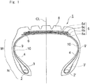
- Fig. 1 is a schematic cross-sectional view showing one example of the tire to be obtained according to the first or third aspect of the production method of the present invention
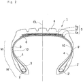
- Fig. 2 is a schematic cross-sectional view showing one example of the tire to be obtained according to the second aspect of the production method of the present invention
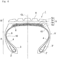
- Fig. 3 is a partially-cut schematic cross-sectional view showing the belt portion of one example of the tire to be obtained according to the first aspect of the production method of the present invention.
- stiffeners 3 and 3' extend outside in the tire radial direction from a pair of bead cores 2 and 2', respectively, and a belt portion 5 comprising multiple belt layers (four layers of 5a to 5d in Fig. 1 , and three layers of 5e to 5g in Fig. 2 ) is arranged outside in the tire radial direction of the carcass ply 4 that is folded from the bead core 2 outside the stiffener 3 to form a toroidal tire casing form, folded at the bead core 2' on the opposite side and fixed outside the stiffener 3'.
- a tread portion 8 is arranged outside in the tire radial direction of the belt portion 5.
- a Sidewall rubber 9 Outside the carcass ply 4 and between the tread portion 8 and the stiffener 3, arranged is a Sidewall rubber 9.
- the portion where the Sidewall rubber 9 is arranged is referred to as a side portion M, and the inside portion in the tire radial direction of the Sidewall M is referred to as a bead portion N.
- a bead portion N In the bead portion N, arranged are the bead cores 2 and 2', the stiffeners 3 and 3', etc.
- an inner liner 10 serving as an air penetration-preventing layer.
- a belt wedge rubber 6 is arranged between the vicinity of the end of the inside belt layer 5b to form a crossing layer and the vicinity of the end of the outside belt layer 5c to form a crossing layer, and at the end of each of the belt layers 5a to 5d, arranged is a belt end cover rubber 7 (7a to 7d) to cover the end of each layer.
- the belt portion 5 includes the belt wedge rubber 6 and the bend end cover rubber 7.
- the belt layers 5a to 5d in the belt portion 5 shown in Fig. 1 and Fig. 3 are all composed of a reinforcing material (especially steel cord) and a coating rubber composition to coat it.
- a belt wedge rubber 6 is arranged between the vicinity of the end of the belt layer 5e to form a crossing layer and the vicinity of the end of the layer 5f, and at the end of each of the belt layers 5e to 5g, arranged is a belt end cover rubber 7 (not shown, but having the same configuration as in Fig. 3 ) to cover the end of each layer.
- the belt portion includes the belt wedge rubber 6 and the bend end cover rubber 7.
- the carcass ply 4 shown in Figs. 1 and 2 is composed of a reinforcing material (especially steel cod) and a coating rubber composition.
- the center line CL of the tire cross-sectional view shown in Figs. 1 , 2 , 4 and 5 is referred to as a crown center.
- Figs. 4 and 5 are schematic cross-sectional views each showing an example of a tire casing A and a precured tread member B in the first to third aspects of the production method for a tire casing or a tire of the present invention (hereinafter this may be abbreviated as the production method of the present invention).
- the casing portion comprising at least a belt portion 5, a side portion M and a bead portion N is cured to form the tire casing A.
- the tire casing A there is arranged a thin layer of a part of tread rubber outside in the tire radial direction of the belt portion 5. This is for bettering the bonding of the tire casing to the precured tread member B.
- the configuration of the belt portion 5 is not defined, but in case where the belt portion is composed of four belt layers 5a to 5d, it is desirable that the belt portion is composed of the innermost belt layer 5a, the inside belt layer 5b to form a crossing layer, the outside belt layer 5c to form a crossing layer, and the outermost belt layer 5d.
- the innermost belt layer 5e in the second aspect of the production method of the present invention preferably forma a crossing layer with the overlying layer, the belt layer 5f.
- the above-mentioned coating rubber composition is used as the coating rubber composition for all the belt layers 5e to 5g, but may be used for any one of those layers .
- crossing layer is also referred to as a cord crossing layer, which is such that between the adjacent two layers, the cords are arranged in different directions relative to the equatorial plane of the tire therebetween, and means a gradient belt layer having a mutually crossing cord arrangement.
- the carcass ply 4 in the third aspect of the production method of the present invention forms a toroidal tire casing form, and is an important member in order that the tire can function as a pressure tight case. Improving the cracking resistance after long-term use of the coating rubber composition for the carcass ply 4 is important for improving the durability of the tire.
- the carcass ply is composed of a reinforcing material of steel cords and a coating rubber composition, and improving the cracking resistance of the tire shoulder portion and the carcass ply edge is important.
- the carbon black having a nitrogen adsorption specific surface area of from 25 to 99 m 2 /g as defined in JIS K 6217-2 :2001 that is used in the coating rubber composition for the outermost belt layer 5d in the first aspect of the production method of the present invention the carbon black having a nitrogen adsorption specific surface area of from 25 to 99 m 2 /g as defined in JIS K 6217-2:2001 that is used in the coating rubber composition for the innermost belt layer 5e in the second aspect, or the carbon black having a nitrogen adsorption specific surface area of from 25 to 90 m 2 /g as defined in JIS K 6217-2:2001 that is used in the coating rubber composition for the carcass ply 4 in the third aspect, for example, there are mentioned HAF (nitrogen adsorption specific surface area: 75 to 80 m 2 /g), HS-HAF (nitrogen adsorption specific surface area: 78 to 83 m 2 /g), LS-HAF (nitrogen adsorption specific
- silica may be incorporated in the coating rubber composition for the outermost belt layer 5d in the first aspect of the production method of the present invention, or the coating rubber composition for the innermost belt layer 5e in the second aspect, or the coating rubber composition for the carcass ply 4 in the third aspect.
- silica is incorporated in an amount of at most 10 parts by mass per 100 parts by mass of the rubber component in the coating rubber composition.
- any commercially-available silica is usable here, but above all, preferred is precipitated silica, fumed silica or colloidal silica, and more preferred is precipitated silica.
- the BET specific surface area (as measured according to ISO 5794/1) of silica for use herein is from 40 to 350 m 2 /g. Silica of which the BET specific surface area falls within the range is advantageous in that it satisfies both rubber-reinforcing capability and dispersibility in the rubber component.
- silica of which the BET specific surface area falls within a range of from 80 to 350 m 2 /g is more preferred; silica of which the BET specific surface area falls within a range of from 120 to 350 m 2 /g is even more preferred.
- the rubber component for use in the coating rubber composition for the outermost belt layer 5d in the first aspect of the production method of the present invention, or the coating rubber composition for the innermost belt layer 5e in the second aspect, or the coating rubber composition for the carcass ply 4 in the third aspect preferred is natural rubber and/or synthetic polyisoprene rubber (IR), and more preferred is natural rubber.
- IR natural rubber and/or synthetic polyisoprene rubber
- natural rubber accounts for at least 60% by mass of the rubber component, more preferably at least 70% by mass, even more preferably at least 80% by mass.
- Especially preferred is use of natural rubber alone.
- the other synthetic rubber includes polybutadiene rubber (BR), styrene-butadiene copolymer (SBR), styrene-isoprene copolymer (SIR), etc.
- BR polybutadiene rubber
- SBR styrene-butadiene copolymer
- SIR styrene-isoprene copolymer
- an organic acid cobalt salt is incorporated in an amount of at most 0.4 parts by mass as the cobalt amount per 100 parts by mass of the rubber component therein, more preferably in an amount of from 0.01 to 0.4 parts by mass, even more preferably from 0.02 to 0.3 parts by mass.
- an organic acid cobalt salt is incorporated in an amount of at most 0.4 parts by mass as the cobalt amount, then the aging resistance of the coating rubber composition can be favorably prevented from lowering.
- Incorporating an organic acid cobalt salt in an amount of at least 0.01 parts by mass as the cobalt amount is more preferred as increasing the initial adhesiveness of the composition.
- the organic acid cobalt salt includes cobalt naphthenate, cobalt rosinate, cobalt stearate, other cobalt salts of linear or branched monocarboxylic acids having from 5 to 20 carbon atoms or so (for example, trade name "Manobond C" Series by OM Group Inc.), etc.
- rubber is incorporated as a vulcanizing agent, in an amount of at most 7.0 parts by mass per 100 parts by mass of the rubber component therein. More preferably, the amount falls within a range of from 3.0 to 7.0 parts by mass, even more preferably from 4.0 to 6.0 parts by mass. Incorporating sulfur in an amount of at most 7.0 parts by mass can favorably prevent the aging resistance of the coting rubber composition from lowering. Incorporating sulfur in an amount of at least 3.0 parts by mass is more preferred as improving the initial adhesiveness of the composition.
- any other additives for example, a vulcanization activator such as zinc flower, organic acid (stearic acid, etc.) or the like, a vulcanization accelerator, an inorganic filler except silica, an antiaging agent, an ozone degradation inhibitor, a softening agent or the like may be added to the coating rubber composition for the outermost belt layer 5d in the first aspect of the production method of the present invention, or the coating rubber composition for the innermost belt layer 5e in the second aspect or the coating rubber composition for the carcass ply 4 in the third aspect.
- a vulcanization activator such as zinc flower, organic acid (stearic acid, etc.) or the like
- a vulcanization accelerator such as zinc flower, organic acid (stearic acid, etc.) or the like
- an inorganic filler except silica such as an antiaging agent, an ozone degradation inhibitor, a softening agent or the like
- a sulfenamide-type accelerator such as N,N'-dicyclohexyl-2-benzothiazolylsulfenamide, N-cyclohexyl-2-benzothiazolylsulfenamide, N-tert-butyl-2-benzothiazolylsulfenamide, N-oxydiethylene-2-benzothiazolylsulfenamide, etc.
- a thiazol-type accelerator such as 2-mercaptobenzothiazole, di-2-benzothiazolyl disulfide, etc.
- a thiuram-type accelerator such as tetrabenzylthiuram disulfide, tetramethylthiuram disulfide, tetraethylthiuram disulfide, tetrakis(2-ethylhexyl)thiuram disulfide, tetramethylthiuram monosulfide, etc.
- the loss tangent (tan ⁇ ) under an initial load of 160 g at a frequency of 52 Hz, a strain of 2% and a measurement temperature of 25°C of the coating rubber composition for the outermost belt layer 5d in the belt portion 5 is preferably at most 0.17 from the viewpoint of improving the low-heat-generation property of the composition.
- the loss tangent (tan ⁇ ) under an initial load of 160 g at a frequency of 52 Hz, a strain of 2% and a measurement temperature of 25°C of the coating rubber composition for the innermost belt layer 5e in at least the tire radial direction of the belt layers in the belt portion 5 is preferably at most 0.17 from the viewpoint of improving the low-heat-generation property of the composition.
- the loss tangent (tan ⁇ ) under an initial load of 160 g at a frequency of 52 Hz, a strain of 2% and a measurement temperature of 25°C of the coating rubber composition for carcass ply 4 is preferably at most 0.17 from the viewpoint of improving the low-heat-generation property of the composition.
- the kneading apparatus for use for producing the coating rubber composition in the present invention includes a Banbury mixer, a roll an intensive mixer, etc.
- an unvulcanized casing portion is formed.
- the casing portion can be formed in the same manner as that for a forming process for a green tire in a known tire production method. For example, a carcass ply rubberized with unvulcanized rubber is wound around a forming drum, a bead core is set around both ends thereof, and thereafter the two ends are folded, and further unvulcanized rubber of a Sidewall portion is stuck thereto.
- the center part in the width direction is expanded to form a toroidal form of which the cross section is horseshoe, and thereafter an unvulcanized belt layer is arranged around the outer periphery of the carcass layer, and preferably a thin layer having the same rubber composition as that of the inner layer of the tread portion 8 is stuck thereonto to provide a casing portion.
- the casing portion is set in a vulcanization device (mold), and vulcanized and molded therein to thereby produce the tire casing A having a part of the tread portion 8 or not having the tread portion 8 at all.
- the vulcanization method for the casing portion is a method of surrounding the outside of the casing portion by the use of the vulcanization mold, and the casing portion is vulcanized and molded in such a manner that the bead portion side of the casing portion is heated by a first heating means, the belt portion side of the casing portion is heated by a second heating means, and the quantity of heat per unit volume to be given to the belt portion side by the second heating means is smaller than the quantity of heat per unit volume to be given to the bead portion side by the first heating means.
- the thickness of the belt portion side of the casing portion is small as compared with the maximum thickness of the bead portion N, and therefore there exists a latest vulcanization point inside the bead portion N.
- the carcass ply on the belt portion side and/or the shoulder portion (tire shoulder portion) side is not overvulcanized, and favorably as a result, the adhesiveness to steel cords (both the initial adhesiveness and the adhesiveness after long-term use thereto) of the coating rubber composition of the outermost belt layer 5d and/or the coating rubber composition of the carcass ply 4 betters, tan ⁇ lowers and the low-heat-generation property of the composition betters.
- the casing portion is vulcanized to produce the tire casing A
- the casing portion is put into a vulcanization mold, and pressure and heat are given thereto from inside the casing portion by the use of a vulcanization bladder therein, and in this case, from the first heating means for the part of the vulcanization mold that faces the bead portion N of the casing portion, the casing portion may be heated at a higher temperature, and from the second heating means for the part of the vulcanization mold that faces the belt portion side of the casing portion, the casing portion may be heated at a lower temperature than from the first heating means.
- the ultimate temperature of the outermost belt layer 5d (especially the latest vulcanization point of the outermost belt layer 5d) (hereinafter referred to as ultimate temperature) during vulcanization of the casing portion is from 110 to 160°C
- the ultimate temperature of the bead portion N (especially the latest vulcanization point of the bead portion N) is from 125 to 180°C
- the ultimate temperature at the latest vulcanization point of the outermost belt layer 5d is lower by from 2 to 25°C than the ultimate temperature at the latest vulcanization point of the bead portion N, more preferably by from 4 to 25°C, even more preferably by from 4 to 20°C.
- This is for preventing the belt portion side from being overvulcanized and for improving the initial adhesiveness to steel cords and the low-heat-generation property of the coating rubber composition for the outermost belt layer 5d.
- the vulcanization can go on favorably; and when 160°C or lower, the initial adhesiveness to steel cords can favorably better.
- the ultimate temperature of the bead portion N especially the latest vulcanization point of the bead part N
- the vulcanization time for the tire casing A can be favorably shortened; and when 180°C or lower, the durability of the bead portion can favorably better.
- the ultimate temperature of the innermost belt layer 5e (especially the latest vulcanization point of the innermost belt layer 5e) during vulcanization of the casing portion is from 110 to 160°C
- the ultimate temperature of the bead portion N (especially the latest vulcanization point of the bead portion N) is from 125 to 180°C
- the ultimate temperature at the latest vulcanization point of the innermost belt layer 5e is lower by from 2 to 25°C than the ultimate temperature of the bead portion N, more preferably by from 4 to 25°C, even more preferably by from 4 to 20°C.
- the vulcanization can go on favorably; and when 160°C or lower, the initial adhesiveness to steel cords can favorably better.
- the ultimate temperature of the bead portion N especially the latest vulcanization point of the innermost belt layer 5e
- the vulcanization time for the tire casing A can be favorably shortened; and when 180°C or lower, the durability of the bead portion can favorably better.
- a tread material of an unvulcanized rubber of which the cross section in the width direction is nearly trapezoidal is extruded through an extruder (not shown), and then cut in a predetermined length, and thereafter the thus-cut strip-shaped tread material is set in a vulcanization mold composed of, for example, an upper mold portion and a lower mold potion, and vulcanized therein to give a ring-shaped precured tread member B.
- a vulcanization mold composed of, for example, an upper mold portion and a lower mold potion, and vulcanized therein to give a ring-shaped precured tread member B.
- the curing condition is preferably at from 100 to 185°C or so for a period of time for which the curing of the precured tread member B can be completely cured.
- the tire casing surface that has been kept in contact with the mold surface during molding has the property of hardly crosslinking with the unvulcanized rubber, and therefore for removing (cutting off) the surface layer rubber of the outer surface to be the adhesive face between the tire casing A and the precured tread member B for the purpose of securing the adhesiveness therebetween, it is desirable that the adhesive face between the tire casing A and the precured tread member B is previously buffed by the use of a buffing machine or the like.
- the surface layer rubber to be cut off is an extremely thin layer having a thickness of at most 0.001 mm in view of the object thereof.
- the surface roughness of the buffed surface could be within a suitable range.
- the adhesive face may be buffed; and above all, preferred is use of a nonwoven fabric-made buffing material for extremely thinning the surface layer rubber to be buffed to have a thickness of from 10 nm to 1 mm.
- the force given for buffing can be dispersed by the spring effect of the buffing material, which is therefore free from troubles of overcutting or deep scratching.
- the nonwoven fabric-made buffing material is a favorable buffing material for uniformly and thinly cutting (roughening) the surface layer in the manner as above.
- the nonwoven fabric-made buffing material can be fitted to an already-existing buffing machine for use herein for buffing.
- the nonwoven fabric-made buffing material concretely mentioned are Sumitomo 3M Limited's "Scotch-Brite", etc.
- the outer surface to be the adhesive face between the tire casing A and the precured tread member B is preferably uniformly roughened in the manner as mentioned above, for further increasing the adhesiveness owing to the anchoring effect thereof.
- the tire casing A and the precured tread member B are bonded together and integrally vulcanized and molded to give the tire 1.
- the tire casing A and the precured tread member B are bonded via an unvulcanized cushion rubber layer, and vulcanized and molded.
- the unvulcanized cushion rubber layer may be an ordinary sheet-like cushion rubber, or a liquid rubber may be applied to the adhesive face to form the unvulcanized cushion rubber layer thereon.
- the cushion rubber composition if desired, various chemicals used in ordinary rubber industry, such as carbon black as a reinforcing filler, as well as a softening agent (oil), an antiaging agent, a crosslinking agent such as sulfur or the like may be suitably incorporated, in addition to rubber components, various vulcanization accelerator components and a crosslinking component used in ordinary rubber compositions .
- the rubber component usable is natural rubber (NR) or synthetic rubber either singly or as combined.
- the synthetic rubber includes, for example, synthetic polyisoprene rubber, polybutadiene rubber (BR), styrene-butadiene rubber (SBR), butyl rubber, halogenobutyl rubber, etc.
- BR polybutadiene rubber
- SBR styrene-butadiene rubber
- halogenobutyl rubber etc.
- a tread rubber composition especially tread base rubber composition.
- the tire casing A to which the precured tread member B has been stuck is conveyed into a vulcanization apparatus not shown (for example, a vulcanizer or a steam pan), in which the unvulcanized cushion rubber layer is vulcanized to give the tire 1.
- a vulcanization apparatus for example, a vulcanizer or a steam pan
- the unvulcanized cushion rubber layer is vulcanized to give the tire 1.
- the precured tread member B is co-vulcanized and bonded to the outer periphery of the crown portion of the tire casing A.
- the vulcanization condition is preferably at from 60 to 140°C or so and for a period of time for which the cushion rubber can be completely vulcanized.
- the ultimate temperature at the latest vulcanization point of the outermost belt layer 5d in the first aspect of the production method of the present invention in bonding the tire casing A and the precured tread member B together and integrally vulcanizing them is preferably lower than the ultimate temperature at the latest vulcanization point of the outermost belt layer 5d in vulcanizing the casing portion.
- the ultimate temperature at the latest vulcanization point of the innermost belt layer 5e in the second aspect of the production method of the present invention in bonding the tire casing A and the precured tread member B together and integrally vulcanizing them is preferably lower than the ultimate temperature at the latest vulcanization point of the innermost belt layer 5e in vulcanizing the casing portion.
- the ultimate temperature of the carcass ply 4 in the crown center position in the third aspect of the production method of the present invention in bonding the tire casing A and the precured tread member B together and integrally vulcanizing them is preferably lower than the ultimate temperature of the carcass ply 4 in the crown center position in vulcanizing the casing portion.
- each trial tire was tested for tan ⁇ under an initial load of 160 g and at a frequency of 52 Hz, a strain of 2% and a measurement temperature of 25°C.
- the tires having a smaller value have a better low-heat-generation property.
- a crack of 0.5 mm was given to the center part of a JIS No. 3 test piece after long-term thermal aging, and repeated fatigue was given thereto at room temperature and at a strain of from 50 to 100%, and the frequency of fatigue repetition until the sample was cut was counted. The value at each strain was determined, and the found data were averaged to give a mean value of the tested composition.
- a molded and vulcanized trial tire was given a side force of 15 kN under a normal inner pressure and a normal load in an atmosphere at 40°C and at a speed of 60 km/hr, and the drum test was carried out for 2 days. After the test, the innermost belt layer was taken out, and the length of the extended crack at the end of the belt layer was measured.
- the value of Comparative Example 21 was referred to as 100
- the value of Example 23 was referred to as 100
- a molded and vulcanized trial tire was given a side force of 15 kN under a normal inner pressure and a normal load in an atmosphere at 40°C and at a speed of 60 km/hr, and the drum test was carried out for 2 days.
- the coating rubber of the carcass ply positioned at the center between the end point of the innermost belt layer 5a and the maximum width position of the tire was taken out, and the rubber sample was given a crack of 0.2 mm and given repeated fatigue at room temperature and at a strain of from 50 to 100%, and the frequency of repeated fatigue until cutting of the sample was counted.
- the value at each strain was determined, and the found data were averaged to give a mean value of the tested tire.
- the outermost belt layer temperature in tire vulcanization was simulated by burying a thermocouple in the outermost belt layer and measuring the temperature change relative to the vulcanization time in the vulcanization method for a tire having a tire size of 11R 22.5 mentioned below, and by feeding back the results to the vulcanization temperature for the test piece.
- Tan ⁇ was measured according to the above-mentioned method.
- a JIS No. 3 test piece was sealed up in a container having a nitrogen atmosphere, and left in a gear oven at 100°C for 24 hours to give a JIS No. 3 test piece after long-term thermal aging.
- the JIS No. 3 test piece after long-term thermal aging was tested for cracking resistance after long-term use according to the above-mentioned method. The results are shown in Tables 2 and 3.
- the belt portion was composed of 4 belt layers.
- the casing portion was vulcanized according to a method of surrounding the casing portion from the outside by a vulcanization mold and pressurizing and heating it from the inside by the use of a vulcanization bladder (pressurizing with high-pressure steam at 150°C), thereby producing a tire casing.
- the first heating means of the vulcanization mold block that faced the bead portion side of the casing portion was kept at 170°C
- the second heating means of the vulcanization mold block that faced the belt portion side of the casing portion was kept at 140°C. Accordingly, the quantity of heat per unit volume to be given to the belt portion side by the second heating means was made smaller than the quantity of heat per unit volume to be given to the bead portion side by the first heating means.
- the ultimate temperature at the latest vulcanization point of the outermost belt layer was 140°C
- the ultimate temperature at the latest vulcanization point of the bead portion was 155°C.
- the vulcanization time was 30 minutes in every case.
- a precured tread member was prepared through vulcanization molding under heat at 160°C to have a tread pattern previously given thereto.
- each precured tread member was stuck to each tire casing, and thereafter vulcanized in a vulcanization apparatus at 120°C for 2 hours, thereby giving a tire with the tire casing and the precured tread member bonding together.
- the ultimate temperature at the latest vulcanization point of the outermost belt layer was 120°C.
- 16 types of the coating rubber compositions of Comparative Examples 1 to 10, 12, 14, 15, 17, 19 and 20 among the above were used for the outermost belt layer to prepare 16 types of unvulcanized casing portions, for which the tire size was 11R 22.5 in all cases.
- An unvulcanized tread member was stuck to the outside in the tire radial direction of the unvulcanized casing portion, thereby producing 16 types of unvulcanized tires.
- the belt portion was composed of 4 belt layers.
- Table 1 Formulation (part by mass) Coating Rubber Composition for Outermost Belt layer Cushion Rubber Natural Rubber As in Table 2 and Table 3 100 Synthetic Isoprene Rubber - Carbon Black 35 *1 Silica - Spindle Oil - 10 Antiaging Agent *2 2 2 Organic Acid Cobalt Salt *3 1 - Zinc Flower 8 5 Stearic Acid 1 3 Accelerator DZ *4 1 - Accelerator TBzTD *5 - 0.2 Accelerator NS *6 - 0.8 Accelerator M *7 - 0.5 Sulfur 5 3 [Notes] *1: HAF(N-330), Asahi Carbon's trade name "Asahi#70" (nitrogen adsorption specific surface area: 77 m 2 /g) *2: N-(1,3-dimethylbutyl)-N'-phenyl-p-phenylenediamine, Ouchi Shinko Chemical Industry's trade name "Nocrac 6C” *3: OM Group's trade name
- the innermost belt layer temperature in tire vulcanization was simulated by burying a thermocouple in the innermost belt layer and measuring the temperature change relative to the vulcanization time in the vulcanization method for a tire having a tire size of 11R 22.5 mentioned below, and by feeding back the results to the vulcanization temperature for the test piece. Tan ⁇ was measured according to the above-mentioned method. The measurement results are shown in Tables 5 and 6.
- the belt portion was composed of 3 belt layers of which the innermost belt layer was a crossing layer.
- the casing portion was vulcanized according to a method of surrounding the casing portion from the outside by a vulcanization mold and pressurizing and heating it from the inside by the use of a vulcanization bladder (pressurizing with high-pressure steam at 150°C), thereby producing a tire casing.
- the first heating means of the vulcanization mold block that faced the bead portion side of the casing portion was kept at 170°C
- the second heating means of the vulcanization mold block that faced the belt portion side of the casing portion was kept at 140°C. Accordingly, the quantity of heat per unit volume to be given to the belt portion side by the second heating means was made smaller than the quantity of heat per unit volume to be given to the bead portion side by the first heating means.
- the ultimate temperature at the latest vulcanization point of the innermost belt layer was 150°C
- the ultimate temperature at the latest vulcanization point of the bead portion was 155°C.
- the vulcanization time was 30 minutes in every case.
- a precured tread member was prepared through vulcanization molding under heat at 160°C to have a tread pattern previously given thereto.
- the bonding face of the tire casing and that of the precured tread member were buffed with a buffing machine.
- a cushion rubber to bond the tire casing and the precured tread member was produced according to the formulation shown in Table 4.
- the unvulcanized cushion rubber was first stuck to the bonding face of the tire casing.
- each precured tread member was stuck to each tire casing, and thereafter vulcanized in a vulcanization apparatus (vulcanizer) at 120°C for 2 hours, thereby giving a tire with the tire casing and the precured tread member bonding together.
- the ultimate temperature at the latest vulcanization point of the innermost belt layer was 120°C.
- 15 types of the coating rubber compositions of Comparative Examples 21 to 26, 28, 29, 31, 33 to 35, 37, 39 and 40 among the above were used for the innermost belt layer to prepare 15 types of unvulcanized casing portions, for which the tire size was 11R 22.5 in all cases.
- An unvulcanized tread member was stuck to the outside in the tire radial direction of the unvulcanized casing portion, thereby producing 15 types of unvulcanized tires.
- the belt portion was composed of 3 belt layers of which the innermost belt layer was a crossing layer.
- Table 4 Formulation (part by mass) Coating Rubber Composition for Innermost Belt layer Cushion Rubber Natural Rubber As in Table 5 and Table 6 100 Synthetic Isoprene Rubber - Carbon Black 50 *21 Silica - Oil *22 - 10 Antiaging Agent *23 2 2 Organic Acid Cobalt Salt *24 1 - Zinc Flower 8 5 Stearic Acid 1 3 Accelerator NS *25 - 0.8 Accelerator DZ *26 1 - Accelerator TBzTD *27 - 0.2 Sulfur 5 3 [Notes] *21: HAF(N-330), Asahi Carbon's trade name "Asahi#70" (nitrogen adsorption specific surface area: 77 m 2 /g) *22: Spindle oil *23: N-(1,3-dimethylbutyl)-N'-phenyl-p-phenylenediamine, Ouchi Shinko Chemical Industry's trade name "Nocrac 6C” *24: OM Group's trade name "Manobond C
- the belt portion was composed of 4 belt layers.
- the casing portion was vulcanized according to a method of surrounding the casing portion from the outside by a vulcanization mold and pressurizing and heating it from the inside by the use of a vulcanization bladder (pressurizing with high-pressure steam at 150°C), thereby producing a tire casing.
- the first heating means of the vulcanization mold block that faced the bead portion side of the casing portion was kept at 170°C
- the second heating means of the vulcanization mold block that faced the belt portion side of the casing portion was kept at 140°C. Accordingly, the quantity of heat per unit volume to be given to the belt portion side by the second heating means was made smaller than the quantity of heat per unit volume to be given to the bead portion side by the first heating means.
- the ultimate temperature at the latest vulcanization point of the outermost belt layer was 140°C
- the ultimate temperature of the carcass ply at the crown center position was 150°C
- the ultimate temperature at the latest vulcanization point of the bead portion was 155°C.
- the vulcanization time was 30 minutes in every case.
- a precured tread member was prepared through vulcanization molding under heat at 160°C to have a tread pattern previously given thereto.
- each precured tread member was stuck to each tire casing, and thereafter vulcanized in a vulcanization apparatus at 120°C for 2 hours, thereby giving a tire with the tire casing and the precured tread member bonding together.
- the ultimate temperature at the latest vulcanization point of the outermost belt layer was 120°C
- the ultimate temperature of the carcass ply at the crown center position was 120°C.
- the coating rubber compositions for outermost belt layer of Examples 1 to 14 are all better than the comparative coating rubber compositions for outermost belt layer of Comparative Examples 1 to 20 in point of tan ⁇ and the cracking resistance after long-term use.
- the obtained tires of Examples 1 to 14 all had low rolling resistance and are excellent.
- the coating rubber compositions for innermost belt layer of Examples 15 to 25 are all better than the comparative coating rubber compositions for innermost belt layer of Comparative Examples 21 to 40 in point of tan (and the cracking resistance after long-term use.
- the obtained tires of Examples 15 to 25 all had low rolling resistance and are excellent.
- the coating rubber compositions for carcass ply of Examples 26 to 38 are all better than the comparative coating rubber compositions for carcass ply of Comparative Examples 41 to 59 in point of tan (and the cracking resistance after long-term use.
- the obtained tires of Examples 26 to 38 all had low rolling resistance and are excellent.
- the production method for a tire casing and a tire of the present invention there can be obtained a tire having improved low-heat-generation property and durability, and the production method of the present invention is favorably used for production of various types of pneumatic tires, especially for pneumatic radial tires for light trucks, large-sized vehicles (for trucks, buses, construction vehicles, etc.) and others.
Description
- The present invention relates to a method for producing a tire casing and a tire having improved low-heat-generation property and durability.
- Heretofore, since the rolling resistance of a tire can be reduced by reducing the heat generation from the entire tire to thereby increase fuel economy, it is desired to lower the heat generation from tires. For lowering the heat generation from tires, compounding the tread rubber composition is mainly improved.
- For reducing the rolling resistance mentioned above, some investigations are being made from the aspect of tire structures, and for example,
Patent Reference 1 discloses a heavy loading pneumatic tire equipped with a belt composed of at least three rubber-coated cord belt layers and a tread, wherein the belt comprises a cord-crossed layer of two layers adjacent to each other and an outermost belt layer positioned on the outermost side in the tire radial direction, and the angle between the cord of the outermost belt layer and the cord of the belt layer adjacent to the outermost belt layer is defined to fall within a specific range and the inclination angle of the cord of the outermost belt layer to the tire equator is defined to fall within a specific range, whereby the rolling resistance of the heavy loading pneumatic tire is further reduced. - Further, in addition to the rolling resistance reduction mentioned above, highly-durable tire casing members are needed for enabling retreading multiple times, and in consideration of environmental influences, retreading capable of contributing toward resource saving is necessary, and further, another important problem is how to improve the durability of the belt-coating rubber for heavy loading radial tires. For improving the durability of tires, it is desired to improve the cracking resistance of the coating rubber composition for a tire belt layer, and for example,
Patent Reference 2 discloses a proposal of improving belt durability by incorporating a bisphenol compound into a belt coating rubber composition to thereby improve the adhesiveness thereof to steel cords and the antiaging property thereof. - Also for improving the durability of tires, it is desired to improve fracture resistance of the coating rubber composition for a tire carcass ply, and for example,
Patent Reference 3 discloses a proposal of incorporating a specific compound in a tire carcass ply coating rubber composition relative to 100 parts by mass of the rubber component therein, thereby improving the adhesiveness to steel cords and the fracture resistance thereof to improve the durability of tires. - For increasing the universality of tire production, various tire production methods where tires are vulcanized in two stages are being developed.
- For example,
Patent Reference 4 proposes a tire production method, wherein the tire forming and vulcanizing step is divided into independent two stages A and B, in the stage A, the tire is so assembled as to comprise at least one carcass layer and at most a part of a tread strip as the outermost layer in the radial direction, and subsequently also the surface is vulcanized in a vulcanization mold capable of imparting a predetermined cross-sectional profile to one or a large number of strength carriers, and in the stage B, the tire part is also similarly vulcanized. -
Patent Reference 5 discloses a tire production method, wherein a partial tire is constructed in the step A and the partial tire is subsequently vulcanized, and in the step B, the whole or the remaining part of an unvulcanized tread is added to the partial tire and then vulcanized to give a complete tire, and wherein, in particular, the surface of the whole or the remaining part of the unvulcanized tread is at least partially plasma-treated. - Further,
Patent Reference 6 proposes a tire production method, in which a two-stage vulcanization system is employed for passenger car tires, and which comprises a first vulcanization step of integrating a spiral reinforcing layer and a tread and then patterning the tread, and a second vulcanization step of setting the primary vulcanized product obtained in the first vulcanization step in the outer periphery of a radial carcass ply of a casing side member and then vulcanizing and molding it. - However, according to these tire production methods, the heat-generation property of the tire could not be lowered and the durability thereof could not be improved.
- Accordingly, it is desired to improve tire production methods from the viewpoint of improving the low-heat-generation property and the durability of tires.
US2009/151839 relates to a rubber composition for adhering steel cord for use as a covering composition for steel cords as reinforcing members in tires.EP0909788 teaches a rubber composition for use in various tire members.JP2002069237 US2010/113684 discloses a method of producing a rubber composition from natural rubber latex. -
- Patent Reference 1:
JP-A 2010-120530 - Patent Reference 2:
JP-A 2007-211152 - Patent Reference 3:
JP-A 2009-137541 - Patent Reference 4:
JP-A 08-258179 - Patent Reference 5:
JP-A 2000-79640 - Patent Reference 6:
JP-A 2006-111072 - Given the situation as above, an object of the present invention is to provide a method for producing a tire casing and a tire having improved low-heat-generation property and durability.
- For solving the above-mentioned problems, the present inventors have found that, when along with using a tire production method favorably vulcanizing a tire casing and bonding the vulcanized tire casing and a precured tread member together and integrally vulcanizing and molding them, a specific coating rubber composition is used for at least one layer in the belt portion or the carcass ply of the tire, then the problems with the present invention can be solved, and have completed the present invention.
- Specifically, the present invention provides the following:
- [1] A method for producing a tire casing by vulcanizing a casing portion comprising a belt portion composed of multiple belt layers, a side portion and a bead portion, the method including at least one compounding method selected from the following (a), (b) and (c):
- (a) in which carbon black having a nitrogen adsorption specific surface area of from 25 to 99 m2/g as defined in JIS K 6217-2:2001 is incorporated in the coating rubber composition for the outermost belt layer in the belt portion, in an amount of from 30 to 60 parts by mass per 100 parts by mass of the rubber component therein;
- (b) in which the belt portion is composed of at least three belt layers, and carbon black having a nitrogen adsorption specific surface area of from 25 to 99 m2/g as defined in JIS K 6217-2:2001 is incorporated in the coating rubber composition for at least one belt layer in the belt portion, in an amount of from 40 to 60 parts by mass per 100 parts by mass of the rubber component therein;
- (c) in which the casing portion includes a carcass ply, and carbon black having a nitrogen adsorption specific surface area of from 25 to 90 m2/g as defined in JIS K 6217-2:2001 is incorporated in the coating rubber composition for the carcass ply, in an amount of from 40 to 60 parts by mass per 100 parts by mass of the rubber component therein; and wherein the vulcanization method for the casing portion is a method of surrounding the casing portion from the outside by the use of the vulcanization mold, and the casing portion is vulcanized and molded in such a manner that the bead portion side of the casing portion is heated by a first heating means, the belt portion side of the casing portion is heated by a second heating means, and the quantity of heat per unit volume to be given to the belt portion side by the second heating means is smaller than the quantity of heat per unit volume to be given to the bead portion side by the first heating means;
- [2] A method for producing a tire by forming a tire casing through vulcanization of a casing portion comprising a belt portion composed of multiple belt layers, a side portion and a bead portion, vulcanizing a tread member having at least a tread portion to form a precured tread member, and thereafter bonding the tire casing and the precured tread member together and integrally vulcanizing and molding them into a tire, the method including at least one compounding method selected from the following (a), (b) and (c):
- (a) in which carbon black having a nitrogen adsorption specific surface area of from 25 to 99 m2/g as defined in JIS K 6217-2:2001 is incorporated in the coating rubber composition for the outermost belt layer in the belt portion, in an amount of from 30 to 60 parts by mass per 100 parts by mass of the rubber component therein;
- (b) in which the belt portion is composed of at least three belt layers, and carbon black having a nitrogen adsorption specific surface area of from 25 to 99 m2/g as defined in JIS K 6217-2:2001 is incorporated in the coating rubber composition for at least one belt layer in the belt portion, in an amount of from 40 to 60 parts by mass per 100 parts by mass of the rubber component therein;
- (c) in which the casing portion includes a carcass ply, and carbon black having a nitrogen adsorption specific surface area of from 25 to 90 m2/g as defined in JIS K 6217-2:2001 is incorporated in the coating rubber composition for the carcass ply, in an amount of from 40 to 60 parts by mass per 100 parts by mass of the rubber component therein; and wherein the vulcanization method for the casing portion is a method of surrounding the casing portion from the outside by the use of the vulcanization mold, and the casing portion is vulcanized and molded in such a manner that the bead portion side of the casing portion is heated by a first heating means, the belt portion side of the casing portion is heated by a second heating means, and the quantity of heat per unit volume to be given to the belt portion side by the second heating means is smaller than the quantity of heat per unit volume to be given to the bead portion side by the first heating means.
- According to the present invention, there is provided a method for producing a tire having improved low-heat-generation property and durability, especially having improved cracking resistance after long-term use. According to the production method of the present invention, the degree of vulcanization of the belt portion and/or the carcass ply inside of the belt portion, and accordingly, the rolling resistance of the tire can be reduced and the cracking resistance thereof after long-term use can be improved more.
- Further, according to the production method for a tire casing and a tire of the present invention:
- (1) a two-stage vulcanization divided production method is employed, in which a casing portion comprising a belt portion, a side portion and a bead portion is vulcanized to form a tire casing, a tread member comprising at least a tread portion is vulcanized to form a precured tread member, and the tire casing and the precured tread member are bonded together and integrally vulcanized and molded. Different from this, regarding a thick-gauge tire such as a heavy loading tire or the like produced according to conventional one-stage vulcanization, the thermal conductivity of rubber is low, and during vulcanization, the temperature increase in the inside area of the tire is lower than that in the surface area thereof, and the rubber properties of the tire after vulcanization differ between the area around the surface of the tire and the inside area thereof; however, the difference is solved in the tire produced according to the method of the present invention, and the tire can effectively bring out the characteristics that the belt-covering rubber naturally has, and, as a result, the tire has a low-heat-generation property and the cracking resistance thereof after long-term use can be significantly improved.
In addition, in the tire of the present invention, the belt portion is composed of at least three belt layers, and from 40 to 60 parts by mass of carbon black having a nitrogen adsorption specific surface area of from 25 to 90 m2/g is incorporated in the coating rubber composition for at least one belt layer in the belt portion, whereby the above-mentioned properties can be further improved. - (2) In forming a tire casing by vulcanizing the casing portion, the bead portion side of the casing portion is heated in the first stage, and the belt portion side of the casing portion is heated in the second stage, and the vulcanization molding is so controlled that the quantity of heat per unit volume to be imparted to the belt portion side in the second heating step could be smaller than the quantity of heat per unit volume to be imparted to the bead portion side in the first heating step to thereby impart a large quantity of heat to the latest vulcanization point of the bead portion, and consequently, the vulcanization time can be shortened and the vulcanization degree of the belt portion coating rubber composition and/or the carcass ply coating rubber composition can be controlled with ease.
- As described above, by producing a tire while the tire casing and the tread portion thereof are separated from each other, it is possible to define the optimum vulcanization condition for the belt portion and/or the carcass ply, and accordingly, there can be provided a method for producing a tire excellent in low-heat-generation property, durability and deterioration resistance.
-
- [
Fig. 1 ] This is a schematic cross-sectional view showing one example of a tire obtained according to the production method of the present invention. - [
Fig. 2 ] This is a schematic cross-sectional view showing another example of a tire obtained according to the production method of the present invention. - [
Fig. 3 ] This is a partly-cut, schematic cross-sectional view showing the belt portion of one example of a tire obtained according to the production method of the present invention. - [
Fig. 4 ] This is a schematic cross-sectional view showing one example of a tire casing and a precured tread member for use in the production method of the present invention. - [
Fig. 5 ] This is a schematic cross-sectional view showing another example of a tire casing and a precured tread member for use in the production method of the present invention. - The method for producing a tire casing of the present invention comprises vulcanizing a casing portion comprising a belt portion composed of multiple belt layers, a side portion and a bead portion, and the production method includes at least one compounding method selected from the following (a), (b) and (c):
- (a) in which carbon black having a nitrogen adsorption specific surface area of from 25 to 99 m2/g as defined in JIS K 6217-2:2001 is incorporated in the coating rubber composition for the outermost belt layer in the belt portion, in an amount of from 30 to 60 parts by mass per 100 parts by mass of the rubber component therein;
- (b) in which the belt portion is composed of at least three belt layers, and carbon black having a nitrogen adsorption specific surface area of from 25 to 99 m2/g as defined in JIS K 6217-2:2001 is incorporated in the coating rubber composition for at least one belt layer in the belt portion, in an amount of from 40 to 60 parts by mass per 100 parts by mass of the rubber component therein;
- (c) in which the casing portion includes a carcass ply, and carbon black having a nitrogen adsorption specific surface area of from 25 to 90 m2/g as defined in JIS K 6217-2:2001 is incorporated in the coating rubber composition for the carcass ply, in an amount of from 40 to 60 parts by mass per 100 parts by mass of the rubber component therein.
- The method for producing a tire of the present invention comprises forming a tire casing through vulcanization of a casing portion comprising a belt portion composed of multiple belt layers, a side portion and a bead portion, vulcanizing a tread member having at least a tread portion to form a precured tread member, and thereafter bonding the tire casing and the precured tread member together and integrally vulcanizing and molding them into a tire, and the production method includes at least one compounding method selected from the following (a), (b) and (c) :
- (a) in which carbon black having a nitrogen adsorption specific surface area of from 25 to 99 m2/g as defined in JIS K 6217-2:2001 is incorporated in the coating rubber composition for the outermost belt layer in the belt portion, in an amount of from 30 to 60 parts by mass per 100 parts by mass of the rubber component therein;
- (b) in which the belt portion is composed of at least three belt layers, and carbon black having a nitrogen adsorption specific surface area of from 25 to 99 m2/g as defined in JIS K 6217-2:2001 is incorporated in the coating rubber composition for at least one belt layer in the belt portion, in an amount of from 40 to 60 parts by mass per 100 parts by mass of the rubber component therein;
- (c) in which the casing portion includes a carcass ply, and carbon black having a nitrogen adsorption specific surface area of from 25 to 90 m2/g as defined in JIS K 6217-2:2001 is incorporated in the coating rubber composition for the carcass ply, in an amount of from 40 to 60 parts by mass per 100 parts by mass of the rubber component therein.
- The first to third aspects of the production method for a tire casing or a tire of the present invention are described below sequentially.
- The first aspect of the production method for a tire casing of the present invention comprises vulcanizing a casing portion comprising a belt portion composed of multiple belt layers, a side portion and a bead portion, wherein carbon black having a nitrogen adsorption specific surface area of from 25 to 99 m2/g as defined in JIS K 6217-2:2001 is incorporated in the coating rubber composition for the outermost belt layer in the belt portion, in an amount of from 30 to 60 parts by mass per 100 parts by mass of the rubber component therein.
- The first aspect of the production method for a tire of the present invention comprises forming a tire casing through vulcanization of a casing portion comprising a belt portion composed of multiple belt layers, a side portion and a bead portion, vulcanizing a tread member having at least a tread portion to form a precured tread member, and thereafter bonding the tire casing and the precured tread member together and integrally vulcanizing and molding them into a tire, wherein carbon black having a nitrogen adsorption specific surface area of from 25 to 99 m2/g as defined in JIS K 6217-2:2001 is incorporated in the coating rubber composition for the outermost belt layer in the belt portion, in an amount of from 30 to 60 parts by mass per 100 parts by mass of the rubber component therein.
- The carbon black must have a nitrogen adsorption specific surface area of from 25 to 99 m2/g. This is because, when at least 25 m2/g, then the coating rubber composition can secure the strength, and when at most 99 m2/g, then the low-heat-generation property and the fatigue resistance of the coating rubber composition can be good; and when falling within the range, the low-heat-generation property and the durability of the tire can be bettered. From the viewpoint of placing more value on the low-heat-generation property, the nitrogen adsorption specific surface area is more preferably from 25 to 90 m2/g; from the viewpoint of placing more value on the durability, the nitrogen adsorption specific surface area is more preferably from 33 to 99 m2/g; and from the viewpoint of bettering both the low-heat-generation property and the durability, the nitrogen adsorption specific surface area is more preferably from 33 to 90 m2/g.
- The amount of the carbon black to be incorporated must be from 30 to 60 parts by mass. This is because, when at least 30 parts by mass, then the coating rubber composition can secure the strength, and when at most 60 parts by mass, then the low-heat-generation property and the fatigue resistance of the coating rubber composition can be good; and when falling within the range, the low-heat-generation property and the durability of the tire can be bettered. From these viewpoints, the amount of the carbon black to be incorporated is more preferably from 35 to 60 parts by mass.
- The second aspect of the method for producing a tire casing of the present invention comprises vulcanizing a casing portion comprising a belt portion composed of at least three belt layers, a side portion and a bead portion, wherein carbon black having a nitrogen adsorption specific surface area of from 25 to 99 m2/g as defined in JIS K 6217-2:2001 is incorporated in the coating rubber composition for at least one belt layer in the belt portion, in an amount of from 40 to 60 parts by mass per 100 parts by mass of the rubber component.
- The second aspect of the method for producing a tire of the present invention comprises forming a tire casing through vulcanization of a casing portion comprising a belt portion composed of at least three belt layers, a side portion and a bead portion, vulcanizing a tread member having at least a tread portion to form a precured tread member, and thereafter bonding the tire casing and the precured tread member together and integrally vulcanizing and molding them into a tire, wherein carbon black having a nitrogen adsorption specific surface area of from 25 to 99 m2/g as defined in JIS K 6217-2:2001 is incorporated in the coating rubber composition for at least one belt layer in the belt portion, in an amount of from 40 to 60 parts by mass per 100 parts by mass of the rubber component therein.
- The carbon black must have a nitrogen adsorption specific surface area of from 25 to 99 m2/g. This is because, when at least 25 m2/g, then the coating rubber composition can secure the strength, and when at most 99 m2/g, then the low-heat-generation property and the fatigue resistance of the coating rubber composition can be good; and when falling within the range, the low-heat-generation property and the durability of the tire can be bettered. From these viewpoints, the nitrogen adsorption specific surface area is more preferably from 33 to 99 m2/g, even more preferably from 33 to 90 m2/g.
- The amount of the carbon black to be incorporated must be from 40 to 60 parts by mass. This is because, when at least 40 parts by mass, then the coating rubber composition can secure the strength, and when at most 60 parts by mass, then the low-heat-generation property and the fatigue resistance of the coating rubber composition can be good; and when falling within the range, the low-heat-generation property and the durability of the tire can be bettered. From these viewpoints, the amount of the carbon black to be incorporated is more preferably from 45 to 60 parts by mass.
- In the second aspect of the method for producing a tire of the present invention, preferably, the above-mentioned coating rubber composition is used for the innermost belt layer in the tire radial direction of those at least three belt layers in the belt portion.
- The third aspect of the method for producing a tire casing of the present invention comprises vulcanizing a casing portion comprising a belt portion composed of multiple belt layers, a carcass ply, a side portion and a bead portion, wherein carbon black having a nitrogen adsorption specific surface area of from 25 to 90 m2/g as defined in JIS K 6217-2 :2001 is incorporated in the coating rubber composition for the carcass ply, in an amount of from 40 to 60 parts by mass per 100 parts by mass of the rubber component therein.
- The third aspect of the method for producing a tire of the present invention comprises forming a tire casing through vulcanization of a casing portion comprising a belt portion composed of multiple belt layers, a carcass ply, a side portion and a bead portion, vulcanizing a tread member having at least a tread portion to form a precured tread member, and thereafter bonding the tire casing and the precured tread member together and integrally vulcanizing and molding them into a tire, wherein carbon black having a nitrogen adsorption specific surface area of from 25 to 90 m2/g as defined in JIS K 6217-2 :2001 is incorporated in the coating rubber composition for the carcass ply, in an amount of from 40 to 60 parts by mass per 100 parts by mass of the rubber component therein.
- The carbon black must have a nitrogen adsorption specific surface area of from 25 to 90 m2/g. This is because, when at least 25 m2/g, then the coating rubber composition can secure the strength, and when at most 90 m2/g, then the low-heat-generation property and the fatigue resistance of the coating rubber composition can be good; and when falling within the range, the low-heat-generation property and the durability of the tire can be bettered. From these viewpoints, the nitrogen adsorption specific surface area is more preferably from 33 to 90 m2/g.
- The amount of the carbon black to be incorporated must be from 40 to 60 parts by mass. This is because, when at least 40 parts by mass, then the coating rubber composition can secure the strength, and when at most 60 parts by mass, then the low-heat-generation property and the fatigue resistance of the coating rubber composition can be good; and when falling within the range, the low-heat-generation property and the durability of the tire can be bettered.
- The vulcanization method in the tire production method of the present invention may be hereinafter referred to as "2-stage vulcanization". The conventional method of vulcanizing a raw tire at a time may be hereinafter referred to as "one-stage vulcanization".
- The members of the tire in the first to third aspects of the production method for a tire casing or a tire of the present invention are described below.
Fig. 1 is a schematic cross-sectional view showing one example of the tire to be obtained according to the first or third aspect of the production method of the present invention;Fig. 2 is a schematic cross-sectional view showing one example of the tire to be obtained according to the second aspect of the production method of the present invention;Fig. 3 is a partially-cut schematic cross-sectional view showing the belt portion of one example of the tire to be obtained according to the first aspect of the production method of the present invention. - In the example of the
tire 1,stiffeners 3 and 3' extend outside in the tire radial direction from a pair ofbead cores 2 and 2', respectively, and abelt portion 5 comprising multiple belt layers (four layers of 5a to 5d inFig. 1 , and three layers of 5e to 5g inFig. 2 ) is arranged outside in the tire radial direction of the carcass ply 4 that is folded from thebead core 2 outside thestiffener 3 to form a toroidal tire casing form, folded at the bead core 2' on the opposite side and fixed outside the stiffener 3'. Atread portion 8 is arranged outside in the tire radial direction of thebelt portion 5. - Outside the
carcass ply 4 and between thetread portion 8 and thestiffener 3, arranged is aSidewall rubber 9. The portion where theSidewall rubber 9 is arranged is referred to as a side portion M, and the inside portion in the tire radial direction of the Sidewall M is referred to as a bead portion N. In the bead portion N, arranged are thebead cores 2 and 2', thestiffeners 3 and 3', etc. Inside thecarcass ply 4, arranged is aninner liner 10 serving as an air penetration-preventing layer. - The
belt portion 5 is further described in detail. InFig. 1 andFig. 3 , in the belt layers 5a to 5d (aninnermost belt layer 5a, aninside belt layer 5b to form a crossing layer, anoutside belt layer 5c to form a crossing layer, and anoutermost belt layer 5d), in general, abelt wedge rubber 6 is arranged between the vicinity of the end of theinside belt layer 5b to form a crossing layer and the vicinity of the end of theoutside belt layer 5c to form a crossing layer, and at the end of each of the belt layers 5a to 5d, arranged is a belt end cover rubber 7 (7a to 7d) to cover the end of each layer. Thebelt portion 5 includes thebelt wedge rubber 6 and the bend end coverrubber 7. - The belt layers 5a to 5d in the
belt portion 5 shown inFig. 1 andFig. 3 are all composed of a reinforcing material (especially steel cord) and a coating rubber composition to coat it. - In the
belt layers 5e to 5g shown inFig. 2 , in general, abelt wedge rubber 6 is arranged between the vicinity of the end of thebelt layer 5e to form a crossing layer and the vicinity of the end of thelayer 5f, and at the end of each of thebelt layers 5e to 5g, arranged is a belt end cover rubber 7 (not shown, but having the same configuration as inFig. 3 ) to cover the end of each layer. The belt portion includes thebelt wedge rubber 6 and the bend end coverrubber 7. - The carcass ply 4 shown in
Figs. 1 and2 is composed of a reinforcing material (especially steel cod) and a coating rubber composition. - The center line CL of the tire cross-sectional view shown in
Figs. 1 ,2 ,4 and5 is referred to as a crown center. -
Figs. 4 and5 are schematic cross-sectional views each showing an example of a tire casing A and a precured tread member B in the first to third aspects of the production method for a tire casing or a tire of the present invention (hereinafter this may be abbreviated as the production method of the present invention). In the present invention, the casing portion comprising at least abelt portion 5, a side portion M and a bead portion N is cured to form the tire casing A. In general, in the tire casing A, there is arranged a thin layer of a part of tread rubber outside in the tire radial direction of thebelt portion 5. This is for bettering the bonding of the tire casing to the precured tread member B. - In the first aspect of the production method of the present invention, the configuration of the
belt portion 5 is not defined, but in case where the belt portion is composed of fourbelt layers 5a to 5d, it is desirable that the belt portion is composed of theinnermost belt layer 5a, theinside belt layer 5b to form a crossing layer, theoutside belt layer 5c to form a crossing layer, and theoutermost belt layer 5d. - As shown in
Fig. 2 andFig. 5 , theinnermost belt layer 5e in the second aspect of the production method of the present invention preferably forma a crossing layer with the overlying layer, thebelt layer 5f. In the present invention, it is important to improve the cracking resistance after long-term use of the coating rubber composition. Preferably, the above-mentioned coating rubber composition is used as the coating rubber composition for all thebelt layers 5e to 5g, but may be used for any one of those layers . As described above, it is especially desirable to use the composition as the above-mentioned crossing layer. Here the crossing layer is also referred to as a cord crossing layer, which is such that between the adjacent two layers, the cords are arranged in different directions relative to the equatorial plane of the tire therebetween, and means a gradient belt layer having a mutually crossing cord arrangement. - The carcass ply 4 in the third aspect of the production method of the present invention forms a toroidal tire casing form, and is an important member in order that the tire can function as a pressure tight case. Improving the cracking resistance after long-term use of the coating rubber composition for the
carcass ply 4 is important for improving the durability of the tire. In pneumatic radial tires for vans, large-sized vehicles (for trucks, buses, construction vehicles, etc.) and others, in general, the carcass ply is composed of a reinforcing material of steel cords and a coating rubber composition, and improving the cracking resistance of the tire shoulder portion and the carcass ply edge is important. - As the carbon black having a nitrogen adsorption specific surface area of from 25 to 99 m2/g as defined in JIS K 6217-2 :2001 that is used in the coating rubber composition for the outermost belt layer 5d in the first aspect of the production method of the present invention, the carbon black having a nitrogen adsorption specific surface area of from 25 to 99 m2/g as defined in JIS K 6217-2:2001 that is used in the coating rubber composition for the innermost belt layer 5e in the second aspect, or the carbon black having a nitrogen adsorption specific surface area of from 25 to 90 m2/g as defined in JIS K 6217-2:2001 that is used in the coating rubber composition for the carcass ply 4 in the third aspect, for example, there are mentioned HAF (nitrogen adsorption specific surface area: 75 to 80 m2/g), HS-HAF (nitrogen adsorption specific surface area: 78 to 83 m2/g), LS-HAF (nitrogen adsorption specific surface area: 80 to 85 m2/g), FEF (nitrogen adsorption specific surface area: 40 to 42 m2/g), GPF (nitrogen adsorption specific surface area: 26 to 28 m2/g), SRF (nitrogen adsorption specific surface area: 25 to 28 m2/g), N339 (nitrogen adsorption specific surface area: 88 to 96 m2/g), LI-HAF (nitrogen adsorption specific surface area: 73 to 75 m2/g), IISAF (nitrogen adsorption specific surface area: 97 to 98 m2/g), HS-IISAF (nitrogen adsorption specific surface area: 98 to 99 m2/g), etc. Of those, preferred are HAF, HS-HAF, LS-HAF, FEF, LI-HAF and GPE.
- In addition to carbon black, if desired, silica may be incorporated in the coating rubber composition for the
outermost belt layer 5d in the first aspect of the production method of the present invention, or the coating rubber composition for theinnermost belt layer 5e in the second aspect, or the coating rubber composition for the carcass ply 4 in the third aspect. Preferably, silica is incorporated in an amount of at most 10 parts by mass per 100 parts by mass of the rubber component in the coating rubber composition. - Any commercially-available silica is usable here, but above all, preferred is precipitated silica, fumed silica or colloidal silica, and more preferred is precipitated silica. Preferably, the BET specific surface area (as measured according to ISO 5794/1) of silica for use herein is from 40 to 350 m2/g. Silica of which the BET specific surface area falls within the range is advantageous in that it satisfies both rubber-reinforcing capability and dispersibility in the rubber component. From this viewpoint, silica of which the BET specific surface area falls within a range of from 80 to 350 m2/g is more preferred; silica of which the BET specific surface area falls within a range of from 120 to 350 m2/g is even more preferred. As silicas of those types, usable here are commercial products of Tosoh Silica's trade names "Nipsil AQ" (BET specific surface area = 220 m2/g)and "Nipsil KQ"; Degussa's trade name "Ultrasil VN3" (BET specific surface area = 175 m2/g), etc.
- As the rubber component for use in the coating rubber composition for the
outermost belt layer 5d in the first aspect of the production method of the present invention, or the coating rubber composition for theinnermost belt layer 5e in the second aspect, or the coating rubber composition for the carcass ply 4 in the third aspect, preferred is natural rubber and/or synthetic polyisoprene rubber (IR), and more preferred is natural rubber. In combined use with any other synthetic rubber, it is desirable that natural rubber accounts for at least 60% by mass of the rubber component, more preferably at least 70% by mass, even more preferably at least 80% by mass. Especially preferred is use of natural rubber alone. - The other synthetic rubber includes polybutadiene rubber (BR), styrene-butadiene copolymer (SBR), styrene-isoprene copolymer (SIR), etc.
- Preferably, in the coating rubber composition for the
outermost belt layer 5d in the first aspect of the production method of the present invention, or the coating rubber composition for theinnermost belt layer 5e in the second aspect or the coating rubber composition for the carcass ply 4 in the third aspect, an organic acid cobalt salt is incorporated in an amount of at most 0.4 parts by mass as the cobalt amount per 100 parts by mass of the rubber component therein, more preferably in an amount of from 0.01 to 0.4 parts by mass, even more preferably from 0.02 to 0.3 parts by mass. When an organic acid cobalt salt is incorporated in an amount of at most 0.4 parts by mass as the cobalt amount, then the aging resistance of the coating rubber composition can be favorably prevented from lowering. Incorporating an organic acid cobalt salt in an amount of at least 0.01 parts by mass as the cobalt amount is more preferred as increasing the initial adhesiveness of the composition. - The organic acid cobalt salt includes cobalt naphthenate, cobalt rosinate, cobalt stearate, other cobalt salts of linear or branched monocarboxylic acids having from 5 to 20 carbon atoms or so (for example, trade name "Manobond C" Series by OM Group Inc.), etc.
- Preferably, in the coating rubber composition for the
outermost belt layer 5d in the first aspect of the production method of the present invention, or the coating rubber composition for theinnermost belt layer 5e in the second aspect or the coating rubber composition for the carcass ply 4 in the third aspect, rubber is incorporated as a vulcanizing agent, in an amount of at most 7.0 parts by mass per 100 parts by mass of the rubber component therein. More preferably, the amount falls within a range of from 3.0 to 7.0 parts by mass, even more preferably from 4.0 to 6.0 parts by mass. Incorporating sulfur in an amount of at most 7.0 parts by mass can favorably prevent the aging resistance of the coting rubber composition from lowering. Incorporating sulfur in an amount of at least 3.0 parts by mass is more preferred as improving the initial adhesiveness of the composition. - In addition to the above-mentioned components, any other additives, for example, a vulcanization activator such as zinc flower, organic acid (stearic acid, etc.) or the like, a vulcanization accelerator, an inorganic filler except silica, an antiaging agent, an ozone degradation inhibitor, a softening agent or the like may be added to the coating rubber composition for the
outermost belt layer 5d in the first aspect of the production method of the present invention, or the coating rubber composition for theinnermost belt layer 5e in the second aspect or the coating rubber composition for the carcass ply 4 in the third aspect. - As the vulcanization accelerator, preferably used here is a sulfenamide-type accelerator such as N,N'-dicyclohexyl-2-benzothiazolylsulfenamide, N-cyclohexyl-2-benzothiazolylsulfenamide, N-tert-butyl-2-benzothiazolylsulfenamide, N-oxydiethylene-2-benzothiazolylsulfenamide, etc. If desired, also usable are a thiazol-type accelerator such as 2-mercaptobenzothiazole, di-2-benzothiazolyl disulfide, etc.; a thiuram-type accelerator such as tetrabenzylthiuram disulfide, tetramethylthiuram disulfide, tetraethylthiuram disulfide, tetrakis(2-ethylhexyl)thiuram disulfide, tetramethylthiuram monosulfide, etc.
- Regarding the physical property of the vulcanized rubber, the loss tangent (tanδ) under an initial load of 160 g at a frequency of 52 Hz, a strain of 2% and a measurement temperature of 25°C of the coating rubber composition for the
outermost belt layer 5d in thebelt portion 5 is preferably at most 0.17 from the viewpoint of improving the low-heat-generation property of the composition. - Regarding the physical property of the vulcanized rubber, the loss tangent (tanδ) under an initial load of 160 g at a frequency of 52 Hz, a strain of 2% and a measurement temperature of 25°C of the coating rubber composition for the
innermost belt layer 5e in at least the tire radial direction of the belt layers in thebelt portion 5 is preferably at most 0.17 from the viewpoint of improving the low-heat-generation property of the composition. - Regarding the physical property of the vulcanized rubber, the loss tangent (tanδ) under an initial load of 160 g at a frequency of 52 Hz, a strain of 2% and a measurement temperature of 25°C of the coating rubber composition for carcass ply 4 is preferably at most 0.17 from the viewpoint of improving the low-heat-generation property of the composition.
- The kneading apparatus for use for producing the coating rubber composition in the present invention includes a Banbury mixer, a roll an intensive mixer, etc.
- In case where the casing portion is vulcanized in producing the tire casing A in the production method of the present invention, first an unvulcanized casing portion is formed. The casing portion can be formed in the same manner as that for a forming process for a green tire in a known tire production method. For example, a carcass ply rubberized with unvulcanized rubber is wound around a forming drum, a bead core is set around both ends thereof, and thereafter the two ends are folded, and further unvulcanized rubber of a Sidewall portion is stuck thereto. Next, the center part in the width direction is expanded to form a toroidal form of which the cross section is horseshoe, and thereafter an unvulcanized belt layer is arranged around the outer periphery of the carcass layer, and preferably a thin layer having the same rubber composition as that of the inner layer of the
tread portion 8 is stuck thereonto to provide a casing portion. - The casing portion is set in a vulcanization device (mold), and vulcanized and molded therein to thereby produce the tire casing A having a part of the
tread portion 8 or not having thetread portion 8 at all. - In the production method of the present invention, the vulcanization method for the casing portion (unvulcanized tire casing A) is a method of surrounding the outside of the casing portion by the use of the vulcanization mold, and the casing portion is vulcanized and molded in such a manner that the bead portion side of the casing portion is heated by a first heating means, the belt portion side of the casing portion is heated by a second heating means, and the quantity of heat per unit volume to be given to the belt portion side by the second heating means is smaller than the quantity of heat per unit volume to be given to the bead portion side by the first heating means.
- In ordinary heavy loading tires (for example, pneumatic radial tires for trucks or busses), the thickness of the belt portion side of the casing portion is small as compared with the maximum thickness of the bead portion N, and therefore there exists a latest vulcanization point inside the bead portion N. As described above, when a small quantity of heat per unit volume is given to the belt portion side and a large quantity of heat per unit volume is given to the bead portion side, then the carcass ply on the belt portion side and/or the shoulder portion (tire shoulder portion) side is not overvulcanized, and favorably as a result, the adhesiveness to steel cords (both the initial adhesiveness and the adhesiveness after long-term use thereto) of the coating rubber composition of the
outermost belt layer 5d and/or the coating rubber composition of the carcass ply 4 betters, tanδ lowers and the low-heat-generation property of the composition betters. - Regarding the means of imparting a small quantity of heat per unit volume to the belt portion side and imparting a large quantity of heat per unit volume to the bead portion side, in case where the casing portion is vulcanized to produce the tire casing A, for example, the casing portion is put into a vulcanization mold, and pressure and heat are given thereto from inside the casing portion by the use of a vulcanization bladder therein, and in this case, from the first heating means for the part of the vulcanization mold that faces the bead portion N of the casing portion, the casing portion may be heated at a higher temperature, and from the second heating means for the part of the vulcanization mold that faces the belt portion side of the casing portion, the casing portion may be heated at a lower temperature than from the first heating means.
- In the first and third aspects of the production method of the present invention, preferably, the ultimate temperature of the
outermost belt layer 5d (especially the latest vulcanization point of theoutermost belt layer 5d) (hereinafter referred to as ultimate temperature) during vulcanization of the casing portion is from 110 to 160°C, and the ultimate temperature of the bead portion N (especially the latest vulcanization point of the bead portion N) is from 125 to 180°C, and the ultimate temperature at the latest vulcanization point of theoutermost belt layer 5d is lower by from 2 to 25°C than the ultimate temperature at the latest vulcanization point of the bead portion N, more preferably by from 4 to 25°C, even more preferably by from 4 to 20°C. This is for preventing the belt portion side from being overvulcanized and for improving the initial adhesiveness to steel cords and the low-heat-generation property of the coating rubber composition for theoutermost belt layer 5d. - When the ultimate temperature of the
outermost belt layer 5d (especially the latest vulcanization point of theoutermost belt layer 5d) is 110°C or higher, then the vulcanization can go on favorably; and when 160°C or lower, the initial adhesiveness to steel cords can favorably better. When the ultimate temperature of the bead portion N (especially the latest vulcanization point of the bead part N) is 125°C or higher, then the vulcanization time for the tire casing A can be favorably shortened; and when 180°C or lower, the durability of the bead portion can favorably better. - In the second aspect of the production method of the present invention, preferably, the ultimate temperature of the
innermost belt layer 5e (especially the latest vulcanization point of theinnermost belt layer 5e) during vulcanization of the casing portion is from 110 to 160°C, and the ultimate temperature of the bead portion N (especially the latest vulcanization point of the bead portion N) is from 125 to 180°C, and the ultimate temperature at the latest vulcanization point of theinnermost belt layer 5e is lower by from 2 to 25°C than the ultimate temperature of the bead portion N, more preferably by from 4 to 25°C, even more preferably by from 4 to 20°C. This is for preventing the belt portion side from being overvulcanized and for improving the initial adhesiveness to steel cords and the low-heat-generation property of the coating rubber composition for theinnermost belt layer 5e. - When the ultimate temperature of the
innermost belt layer 5e (especially the latest vulcanization point of theinnermost belt layer 5e) is 110°C or higher, then the vulcanization can go on favorably; and when 160°C or lower, the initial adhesiveness to steel cords can favorably better. When the ultimate temperature of the bead portion N (especially the latest vulcanization point of theinnermost belt layer 5e) is 125°C or higher, then the vulcanization time for the tire casing A can be favorably shortened; and when 180°C or lower, the durability of the bead portion can favorably better. - On the other hand, in case where the precured tread member B is produced, a tread material of an unvulcanized rubber of which the cross section in the width direction is nearly trapezoidal is extruded through an extruder (not shown), and then cut in a predetermined length, and thereafter the thus-cut strip-shaped tread material is set in a vulcanization mold composed of, for example, an upper mold portion and a lower mold potion, and vulcanized therein to give a ring-shaped precured tread member B. In this stage, formed are multiple grooves each extending in the lengthwise direction of the ring-shaped outer surface of the precured tread member B.
- The curing condition is preferably at from 100 to 185°C or so for a period of time for which the curing of the precured tread member B can be completely cured.
- In the tire casing A and the precured tread member B produced in the manner as above, the tire casing surface that has been kept in contact with the mold surface during molding has the property of hardly crosslinking with the unvulcanized rubber, and therefore for removing (cutting off) the surface layer rubber of the outer surface to be the adhesive face between the tire casing A and the precured tread member B for the purpose of securing the adhesiveness therebetween, it is desirable that the adhesive face between the tire casing A and the precured tread member B is previously buffed by the use of a buffing machine or the like. However, the surface layer rubber to be cut off is an extremely thin layer having a thickness of at most 0.001 mm in view of the object thereof.
- Regarding the method of cutting of the surface layer rubber, there is given no specific limitation thereto so far as the surface roughness of the buffed surface could be within a suitable range. Using a grinding stone, a metal-made buffing tool, a nonwoven-made buffing material or the like, the adhesive face may be buffed; and above all, preferred is use of a nonwoven fabric-made buffing material for extremely thinning the surface layer rubber to be buffed to have a thickness of from 10 nm to 1 mm. With the nonwoven fabric-made buffing material, the force given for buffing can be dispersed by the spring effect of the buffing material, which is therefore free from troubles of overcutting or deep scratching. Accordingly, the nonwoven fabric-made buffing material, is a favorable buffing material for uniformly and thinly cutting (roughening) the surface layer in the manner as above. The nonwoven fabric-made buffing material can be fitted to an already-existing buffing machine for use herein for buffing. As the nonwoven fabric-made buffing material, concretely mentioned are Sumitomo 3M Limited's "Scotch-Brite", etc.
- The outer surface to be the adhesive face between the tire casing A and the precured tread member B is preferably uniformly roughened in the manner as mentioned above, for further increasing the adhesiveness owing to the anchoring effect thereof.
- Next, the tire casing A and the precured tread member B are bonded together and integrally vulcanized and molded to give the
tire 1. In this stage, it is desirable that the tire casing A and the precured tread member B are bonded via an unvulcanized cushion rubber layer, and vulcanized and molded. The unvulcanized cushion rubber layer may be an ordinary sheet-like cushion rubber, or a liquid rubber may be applied to the adhesive face to form the unvulcanized cushion rubber layer thereon. - In the cushion rubber composition, if desired, various chemicals used in ordinary rubber industry, such as carbon black as a reinforcing filler, as well as a softening agent (oil), an antiaging agent, a crosslinking agent such as sulfur or the like may be suitably incorporated, in addition to rubber components, various vulcanization accelerator components and a crosslinking component used in ordinary rubber compositions . As the rubber component, usable is natural rubber (NR) or synthetic rubber either singly or as combined. The synthetic rubber includes, for example, synthetic polyisoprene rubber, polybutadiene rubber (BR), styrene-butadiene rubber (SBR), butyl rubber, halogenobutyl rubber, etc. As the rubber composition, preferred here is use of a tread rubber composition (especially tread base rubber composition).
- Next, the tire casing A to which the precured tread member B has been stuck is conveyed into a vulcanization apparatus not shown (for example, a vulcanizer or a steam pan), in which the unvulcanized cushion rubber layer is vulcanized to give the
tire 1. In this stage, the precured tread member B is co-vulcanized and bonded to the outer periphery of the crown portion of the tire casing A. - The vulcanization condition is preferably at from 60 to 140°C or so and for a period of time for which the cushion rubber can be completely vulcanized.
- During the vulcanization, the ultimate temperature at the latest vulcanization point of the
outermost belt layer 5d in the first aspect of the production method of the present invention in bonding the tire casing A and the precured tread member B together and integrally vulcanizing them is preferably lower than the ultimate temperature at the latest vulcanization point of theoutermost belt layer 5d in vulcanizing the casing portion. This is for the purpose of optimizing the degree of vulcanization in vulcanizing the casing portion and the total degree of vulcanization in vulcanizing the tire casing A and the precured tread member B so that they could not be excessively too high, whereby the initial adhesiveness to steel cords, the low-heat-generation property and the durability of the coating rubber composition for theoutermost belt layer 5d can be bettered. - During the vulcanization, the ultimate temperature at the latest vulcanization point of the
innermost belt layer 5e in the second aspect of the production method of the present invention in bonding the tire casing A and the precured tread member B together and integrally vulcanizing them is preferably lower than the ultimate temperature at the latest vulcanization point of theinnermost belt layer 5e in vulcanizing the casing portion. This is for the purpose of optimizing the degree of vulcanization in vulcanizing the casing portion and the total degree of vulcanization in vulcanizing the tire casing A and the precured tread member B so that they could not be excessively too high, whereby the initial adhesiveness to steel cords, the low-heat-generation property and the durability of the coating rubber composition for theinnermost belt layer 5e can be bettered. - During the vulcanization, the ultimate temperature of the carcass ply 4 in the crown center position in the third aspect of the production method of the present invention in bonding the tire casing A and the precured tread member B together and integrally vulcanizing them is preferably lower than the ultimate temperature of the carcass ply 4 in the crown center position in vulcanizing the casing portion. This is for the purpose of optimizing the degree of vulcanization in vulcanizing the casing portion and the total degree of vulcanization in vulcanizing the tire casing A and the precured tread member B so that they could not be excessively too high, whereby the initial adhesiveness to steel cords, the low-heat-generation property and the durability of the coating rubber composition for the carcass ply 4 on the belt potion side and the shoulder portion (tire shoulder portion) side can be bettered.
- The invention is described in more detail with reference to Examples given below, however, the invention is not limited to the following Examples at all.
- The low rolling resistance, tanδ, and the cracking resistance after long-term use were evaluated according to the methods mentioned below.
- Each trial tire was tested in a drum test for the resistance occurring on the tire tread in the running direction in running at a speed of 80 km/hr. The value of Comparative Example 1 in Table 2, the value of Comparative Example 20 in Table 3, the value of Comparative Example 21 in Table 5, the value of Example 25 in Table 6, the value of Comparative Example 41 in Table 8 and the value of Comparative Example 59 in Table 9 each were referred to as 100, and the value of each tested tire was expressed as an index according to the formula mentioned below. The tires having a larger value have a smaller rolling resistance and are better.

- Using Toyo Seiki's spectrometer (dynamic viscoelastometer), each trial tire was tested for tanδ under an initial load of 160 g and at a frequency of 52 Hz, a strain of 2% and a measurement temperature of 25°C. The tires having a smaller value have a better low-heat-generation property.
- A crack of 0.5 mm was given to the center part of a JIS No. 3 test piece after long-term thermal aging, and repeated fatigue was given thereto at room temperature and at a strain of from 50 to 100%, and the frequency of fatigue repetition until the sample was cut was counted. The value at each strain was determined, and the found data were averaged to give a mean value of the tested composition. In Table 2, the value of Comparative Example 1 was referred to as 100, and in Table 3, the value of Example 12 was referred to 100; and the value of each tested composition was expressed as an index according to the formula mentioned below. The compositions having a larger index value have better cracking resistance.

- A molded and vulcanized trial tire was given a side force of 15 kN under a normal inner pressure and a normal load in an atmosphere at 40°C and at a speed of 60 km/hr, and the drum test was carried out for 2 days. After the test, the innermost belt layer was taken out, and the length of the extended crack at the end of the belt layer was measured. In Table 5, the value of Comparative Example 21 was referred to as 100, and in Table 6, the value of Example 23 was referred to as 100; and the mean value of the extended crack lengths of each tire was expressed as an index. The tires having a larger index value have better cracking resistance.

- A molded and vulcanized trial tire was given a side force of 15 kN under a normal inner pressure and a normal load in an atmosphere at 40°C and at a speed of 60 km/hr, and the drum test was carried out for 2 days. After the test, the coating rubber of the carcass ply positioned at the center between the end point of the
innermost belt layer 5a and the maximum width position of the tire was taken out, and the rubber sample was given a crack of 0.2 mm and given repeated fatigue at room temperature and at a strain of from 50 to 100%, and the frequency of repeated fatigue until cutting of the sample was counted. The value at each strain was determined, and the found data were averaged to give a mean value of the tested tire. In Table 8, the value of Comparative Example 41 was referred to as 100, and in Table 9, the value of Example 36 was referred to 100; and the value of each tested tire was expressed as an index according to the formula mentioned below. The tires having a larger index value have better carcass ply cracking resistance.
- As in Tables 1 to 3 each showing the formulations of coating rubber compositions for outermost belt layer, 34 types of coating rubber compositions for use in Examples 1 to 14 and Comparative Examples 1 to 20 were produced according to an ordinary method. The coating rubber composition was vulcanized in the manner of simulating the outermost belt layer temperature in tire vulcanization (in two-stage vulcanization, both temperatures in two stages) thereby preparing test pieces for measurement of tanδ and cracking resistance after long-term use. The outermost belt layer temperature in tire vulcanization was simulated by burying a thermocouple in the outermost belt layer and measuring the temperature change relative to the vulcanization time in the vulcanization method for a tire having a tire size of 11R 22.5 mentioned below, and by feeding back the results to the vulcanization temperature for the test piece.
- Tanδ was measured according to the above-mentioned method. Next, a JIS No. 3 test piece was sealed up in a container having a nitrogen atmosphere, and left in a gear oven at 100°C for 24 hours to give a JIS No. 3 test piece after long-term thermal aging. The JIS No. 3 test piece after long-term thermal aging was tested for cracking resistance after long-term use according to the above-mentioned method. The results are shown in Tables 2 and 3.
- Next, 18 types of the coating rubber compositions of Examples 1 to 14 and Comparative Examples 11, 13, 16 and 18 among the above were used for the outermost belt layer to prepare 18 types of unvulcanized casing portions, for which the tire size was 11R 22.5 in all cases. As shown in
Fig. 4 , the belt portion was composed of 4 belt layers. The casing portion was vulcanized according to a method of surrounding the casing portion from the outside by a vulcanization mold and pressurizing and heating it from the inside by the use of a vulcanization bladder (pressurizing with high-pressure steam at 150°C), thereby producing a tire casing. In this stage, the first heating means of the vulcanization mold block that faced the bead portion side of the casing portion was kept at 170°C, and the second heating means of the vulcanization mold block that faced the belt portion side of the casing portion was kept at 140°C. Accordingly, the quantity of heat per unit volume to be given to the belt portion side by the second heating means was made smaller than the quantity of heat per unit volume to be given to the bead portion side by the first heating means. The ultimate temperature at the latest vulcanization point of the outermost belt layer was 140°C, and the ultimate temperature at the latest vulcanization point of the bead portion was 155°C. The vulcanization time was 30 minutes in every case. - Separately, a precured tread member was prepared through vulcanization molding under heat at 160°C to have a tread pattern previously given thereto.
- Next, the bonding face of the tire casing and that of the precured tread member were buffed with a buffing machine, and then a cushion rubber to bond the tire casing and the precured tread member was produced according to the formulation shown in Table 1. The unvulcanized cushion rubber was stuck to the bonding face of the tire casing.
- Next, each precured tread member was stuck to each tire casing, and thereafter vulcanized in a vulcanization apparatus at 120°C for 2 hours, thereby giving a tire with the tire casing and the precured tread member bonding together. In this case, the ultimate temperature at the latest vulcanization point of the outermost belt layer was 120°C.
- Thus produced, those 18 types of tires (tire size 11R 22.5) were evaluated for the low rolling resistance according to the above-mentioned method. The evaluation results are shown in Tables 2 and 3.
- Next, 16 types of the coating rubber compositions of Comparative Examples 1 to 10, 12, 14, 15, 17, 19 and 20 among the above were used for the outermost belt layer to prepare 16 types of unvulcanized casing portions, for which the tire size was 11R 22.5 in all cases. An unvulcanized tread member was stuck to the outside in the tire radial direction of the unvulcanized casing portion, thereby producing 16 types of unvulcanized tires. As shown in
Fig. 4 , the belt portion was composed of 4 belt layers. These 16 types of unvulcanized tires were vulcanized according to ordinary one-stage vulcanization, thereby producing 16 types of tires. - Thus produced, those 16 types of tires (tire size 11R 22.5) were evaluated for the low rolling resistance according to the above-mentioned method. The evaluation results are shown in Tables 2 and 3.
- [Table 1]
Table 1 Formulation (part by mass) Coating Rubber Composition for Outermost Belt layer Cushion Rubber Natural Rubber As in Table 2 and Table 3 100 Synthetic Isoprene Rubber - Carbon Black 35 *1 Silica - Spindle Oil - 10 Antiaging Agent *2 2 2 Organic Acid Cobalt Salt *3 1 - Zinc Flower 8 5 Stearic Acid 1 3 Accelerator DZ *4 1 - Accelerator TBzTD *5 - 0.2 Accelerator NS *6 - 0.8 Accelerator M *7 - 0.5 Sulfur 5 3 [Notes]
*1: HAF(N-330), Asahi Carbon's trade name "Asahi#70" (nitrogen adsorption specific surface area: 77 m2/g)
*2: N-(1,3-dimethylbutyl)-N'-phenyl-p-phenylenediamine, Ouchi Shinko Chemical Industry's trade name "Nocrac 6C"
*3: OM Group's trade name "Manobond C225" (registered trademark) (cobalt content 22.5%)
*4: N,N'-dicyclohexyl-2-benzothiazolylsulfenamide, Ouchi Shinko Chemical Industry's trade name "Nocceler DZ"
*5: Tetrabenzylthiuram disulfide, Sanshin Chemical Industry's trade name "Sanceler TBZTD"
*6: N-tert-butyl-2-benzothiazolylsulfenamide, Sanshin Chemical Industry's trade name "Sanceler NS"
*7: 2-mercaptobenzothiazole, Ouchi Shinko Chemical Industry's trade name "Nocceler M-P"


- [Table 3]
Table 3 Coating Rubber Composition for Outermost Belt Layer Example Comparative Example 12 13 14 14 15 16 17 18 19 20 Formulation (part by mass) Natural Rubber 70 100 100 70 100 100 100 100 100 100 Synthetic Isoprene Rubber *8 30 - - 30 - - - - - - Carbon Black HAF *9 - 45 - - - - - - 45 - Carbon Black FEF *10 45 - 60 45 25 25 25 25 - 60 Carbon Black GPF *11 - - - - - - - - - - Silica *14 5 5 5 5 - - 5 5 5 5 Vulcanization Method 2-stage vulcaniz ation 2-stage vulcaniz ation 2-stage vulcaniz ation 1-stage vulcaniz ation 1-stage vulcaniz ation 2-stage vulcaniz ation 1-stage vulcaniz ation 2-stage vulcaniz ation 1-stage vulcaniz ation 1-stage vulcaniz ation Evaluation Results Low Rolling Resistance 103 101 100 103 104 104 104 104 101 100 tanδ 0.16 0.19 0.21 0.16 0.14 0.14 0.14 0.14 0.19 0.20 Cracking Resistance after Long-Term Use 100 105 105 88 55 65 58 68 98 95 [Notes]
*8 to *11 and *14 are the same as in Table 2. - As in Tables 4 to 6 each showing the formulations of coating rubber compositions for innermost belt layer, 31 types of coating rubber compositions for use in Examples 15 to 25 and Comparative Examples 21 to 40 were produced according to an ordinary method. The coating rubber composition was vulcanized in the manner of simulating the innermost belt layer temperature in tire vulcanization (in two-stage vulcanization, both temperatures in two stages) thereby preparing test pieces for measurement of tanδ. The innermost belt layer temperature in tire vulcanization was simulated by burying a thermocouple in the innermost belt layer and measuring the temperature change relative to the vulcanization time in the vulcanization method for a tire having a tire size of 11R 22.5 mentioned below, and by feeding back the results to the vulcanization temperature for the test piece. Tanδ was measured according to the above-mentioned method. The measurement results are shown in Tables 5 and 6.
- Next, 16 types of the coating rubber compositions of Examples 15 to 25 and Comparative Examples 27, 30, 32, 36 and 38 among the above were used for the innermost belt layer to prepare 16 types of unvulcanized casing portions, for which the tire size was 11R 22.5 in all cases. As shown in
Fig. 5 , the belt portion was composed of 3 belt layers of which the innermost belt layer was a crossing layer. The casing portion was vulcanized according to a method of surrounding the casing portion from the outside by a vulcanization mold and pressurizing and heating it from the inside by the use of a vulcanization bladder (pressurizing with high-pressure steam at 150°C), thereby producing a tire casing. In this stage, the first heating means of the vulcanization mold block that faced the bead portion side of the casing portion was kept at 170°C, and the second heating means of the vulcanization mold block that faced the belt portion side of the casing portion was kept at 140°C. Accordingly, the quantity of heat per unit volume to be given to the belt portion side by the second heating means was made smaller than the quantity of heat per unit volume to be given to the bead portion side by the first heating means. The ultimate temperature at the latest vulcanization point of the innermost belt layer was 150°C, and the ultimate temperature at the latest vulcanization point of the bead portion was 155°C. The vulcanization time was 30 minutes in every case. - Separately, a precured tread member was prepared through vulcanization molding under heat at 160°C to have a tread pattern previously given thereto.
- The bonding face of the tire casing and that of the precured tread member were buffed with a buffing machine.
- Next, a cushion rubber to bond the tire casing and the precured tread member was produced according to the formulation shown in Table 4. The unvulcanized cushion rubber was first stuck to the bonding face of the tire casing. Subsequently, each precured tread member was stuck to each tire casing, and thereafter vulcanized in a vulcanization apparatus (vulcanizer) at 120°C for 2 hours, thereby giving a tire with the tire casing and the precured tread member bonding together. In this case, the ultimate temperature at the latest vulcanization point of the innermost belt layer was 120°C.
- Thus produced, those 16 types of tires (tire size 11R 22.5) were evaluated for the low rolling resistance and the cracking resistance after long-term use, according to the above-mentioned methods. The evaluation results are shown in Tables 5 and 6.
- Next, 15 types of the coating rubber compositions of Comparative Examples 21 to 26, 28, 29, 31, 33 to 35, 37, 39 and 40 among the above were used for the innermost belt layer to prepare 15 types of unvulcanized casing portions, for which the tire size was 11R 22.5 in all cases. An unvulcanized tread member was stuck to the outside in the tire radial direction of the unvulcanized casing portion, thereby producing 15 types of unvulcanized tires. As shown in
Fig. 5 , the belt portion was composed of 3 belt layers of which the innermost belt layer was a crossing layer. These 15 types of unvulcanized tires were vulcanized according to ordinary one-stage vulcanization, thereby producing 15 types of tires. - Thus produced, those 15 types of tires (tire size 11R 22.5) were evaluated for the low rolling resistance and the cracking resistance after long-term use according to the above-mentioned methods. The evaluation results are shown in Tables 5 and 6.
- [Table 4]
Table 4 Formulation (part by mass) Coating Rubber Composition for Innermost Belt layer Cushion Rubber Natural Rubber As in Table 5 and Table 6 100 Synthetic Isoprene Rubber - Carbon Black 50 *21 Silica - Oil *22 - 10 Antiaging Agent *23 2 2 Organic Acid Cobalt Salt *24 1 - Zinc Flower 8 5 Stearic Acid 1 3 Accelerator NS *25 - 0.8 Accelerator DZ *26 1 - Accelerator TBzTD *27 - 0.2 Sulfur 5 3 [Notes]
*21: HAF(N-330), Asahi Carbon's trade name "Asahi#70" (nitrogen adsorption specific surface area: 77 m2/g)
*22: Spindle oil
*23: N-(1,3-dimethylbutyl)-N'-phenyl-p-phenylenediamine, Ouchi Shinko Chemical Industry's trade name "Nocrac 6C"
*24: OM Group's trade name "Manobond C225" (registered trademark) (cobalt content 22.5%)
*25: N-tert-butyl-2-benzothiazolylsulfenamide, Sanshin Chemical Industry's trade name "Sanceler NS"
*26: N,N'-dicyclohexyl-2-benzothiazolylsulfenamide, Ouchi Shinko Chemical Industry's trade name "Nocceler DZ"
*27: Tetrabenzylthiuram disulfide, Sanshin Chemical Industry's trade name "Sanceler TBZTD"

Table 6 Coating Rubber Composition for Innermost Belt Layer Example Comparative Example 22 23 24 25 33 34 35 36 37 38 39 40 Formulation (part by mass) Natural Rubber 100 70 100 100 100 70 100 100 100 100 100 100 Synthetic Isoprene Rubber *28 - 30 - - - 30 - - - - - - Carbon Black HAF *21 50 45 45 - 50 - 35 35 35 35 45 - Carbon Black FEF *29 - - - 60 - 50 - - - - - 60 Silica *33 5 5 5 5 5 5 - - 5 5 5 5 Vulcanization Method 2-stage vulcan ization 2-stage vulcan ization 2-stage vulcan ization 2-stage vulcan ization 1-stage vulcan ization 1-stage vulcan ization 1-stage vulcan ization 2-stage vulcan ization 1-stage vulcan ization 2-stage vulcan ization 1-stage vulcan ization 1-stage vulcan ization Evaluation Results Low Rolling Resistance 102 103 102 100 101 103 104 104 104 103 102 101 tanδ 0.18 0.16 0.19 0.21 0.19 0.16 0.14 0.14 0.14 0.14 0.19 0.20 Cracking Resistance after Long-Term Use 107 100 108 105 86 88 70 90 75 95 98 95 [Notes]
*21, *28, *29 and *33 are the same as in Table 5. - As in Tables 7 to 9 each showing the formulations of coating rubber compositions for carcass ply, 32 types of coating rubber compositions for use in Examples 26 to 38 and Comparative Examples 41 to 59 were produced according to an ordinary method.
- Next, 17 types of the coating rubber compositions of Examples 26 to 38 and Comparative Examples 50, 52, 55 and 57 among the above were used for carcass ply to prepare 17 types of unvulcanized casing portions, for which the tire size was 11R 22.5 in all cases. As shown in
Fig. 4 , the belt portion was composed of 4 belt layers. The casing portion was vulcanized according to a method of surrounding the casing portion from the outside by a vulcanization mold and pressurizing and heating it from the inside by the use of a vulcanization bladder (pressurizing with high-pressure steam at 150°C), thereby producing a tire casing. In this stage, the first heating means of the vulcanization mold block that faced the bead portion side of the casing portion was kept at 170°C, and the second heating means of the vulcanization mold block that faced the belt portion side of the casing portion was kept at 140°C. Accordingly, the quantity of heat per unit volume to be given to the belt portion side by the second heating means was made smaller than the quantity of heat per unit volume to be given to the bead portion side by the first heating means. The ultimate temperature at the latest vulcanization point of the outermost belt layer was 140°C, the ultimate temperature of the carcass ply at the crown center position was 150°C, and the ultimate temperature at the latest vulcanization point of the bead portion was 155°C. The vulcanization time was 30 minutes in every case. - Separately, a precured tread member was prepared through vulcanization molding under heat at 160°C to have a tread pattern previously given thereto.
- Next, the bonding face of the tire casing and that of the precured tread member were buffed with a buffing machine, and then a cushion rubber to bond the tire casing and the precured tread member was produced according to the formulation shown in Table 7. The unvulcanized cushion rubber was stuck to the bonding face of the tire casing.
- Subsequently, each precured tread member was stuck to each tire casing, and thereafter vulcanized in a vulcanization apparatus at 120°C for 2 hours, thereby giving a tire with the tire casing and the precured tread member bonding together. In this case, the ultimate temperature at the latest vulcanization point of the outermost belt layer was 120°C, and the ultimate temperature of the carcass ply at the crown center position was 120°C.
- Thus produced, those 17 types of tires (tire size 11R 22.5) were evaluated for the low rolling resistance and the cracking resistance after long-term use, according to the above-mentioned methods. The evaluation results are shown in Tables 8 and 9.
- Next, 15 types of the coating rubber compositions of Comparative Examples 41 to 49, 51, 53, 54, 56, 58 and 59 among the above were used for carcass ply to prepare 15 types of unvulcanized casing portions, for which the tire size was 11R 22.5 in all cases. An unvulcanized tread member was stuck to the outside in the tire radial direction of the unvulcanized casing portion, thereby producing 15 types of unvulcanized tires. As shown in
Fig. 4 , the belt portion was composed of 4 belt layers. These 15 types of unvulcanized tires were vulcanized according to ordinary one-stage vulcanization, thereby producing 15 types of tires. - Thus produced, those 15 types of tires (tire size 11R 22.5) were evaluated for the low rolling resistance and the cracking resistance after long-term use according to the above-mentioned methods. The evaluation results are shown in Tables 8 and 9.
[Table 7]Table 7 Formulation (part by mass) Coating Rubber Composition for Carcass Ply Cushion Rubber Natural Rubber As in Table 8 and Table 9 100 Synthetic Isoprene Rubber - Carbon Black 35 *41 Silica - Spindle Oil - 10 Antiaging Agent *42 2 2 Organic Acid Cobalt Salt *43 1 - Zinc Flower 8 5 Stearic Acid 1 3 Accelerator DZ *44 1 - Accelerator TBzTD *45 - 0.2 Accelerator NS *46 - 0.8 Accelerator M *47 - 0.5 Sulfur 5 3 [Notes]
*41: HAF(N-330), Asahi Carbon's trade name "Asahi#70" (nitrogen adsorption specific surface area: 77 m2/g)
*42: N-(1,3-dimethylbutyl)-N'-phenyl-p-phenylenediamine, Ouchi Shinko Chemical Industry's trade name "Nocrac 6C"
*43: OM Group's trade name "Manobond C225" (registered trademark) (cobalt content 22.5%)
*44: N,N'-dicyclohexyl-2-benzothiazolylsulfenamide, Ouchi Shinko Chemical Industry's trade name "Nocceler DZ"
*45: Tetrabenzylthiuram disulfide, Sanshin Chemical Industry's trade name "Sanceler TBZTD"
*46: N-tert-butyl-2-benzothiazolylsulfenamide, Sanshin Chemical Industry's trade name "Sanceler NS"
*47: 2-mercaptobenzothiazole, Ouchi Shinko Chemical Industry's trade name "Nocceler M-P"


Table 9 Coating Rubber Composition for Carcass Ply Example Com Comparative Example 36 37 38 53 54 55 56 57 58 59 Formulation (part by mass) Natural Rubber 70 100 100 70 100 100 100 100 100 100 Synthetic Isoprene Rubber *54 30 - - 30 - - - - - - Carbon Black HAF *48 - 45 - - - - - - 45 - Carbon Black FEF *49 45 - 60 45 35 35 35 35 - 60 Carbon Black GPF *50 - - - - - - - - - - Silica *53 5 5 5 5 - - 5 5 5 5 Vulcanization Method 2-stage vulcaniz ation 2-stage vulcaniz ation 2-stage vulcaniz ation 1-stage vulcaniz ation 1-stage vulcaniz ation 2-stage vulcaniz ation 1-stage vulcaniz ation 2-stage vulcaniz ation 1-stage vulcaniz ation 1-stage vulcaniz ation Evaluation Results Low Rolling Resistance 100 101 100 99 103 103 103 103 99 100 Cracking Resistance after Long-Term Use 100 105 106 88 83 95 84 96 90 96 [Notes]
*48 to *50 and *53 are the same as in Table 8.
*54: JSR's polyisoprene rubber (IR), trade name "IR2200" - As obvious from Table 2 and Table 3, the coating rubber compositions for outermost belt layer of Examples 1 to 14 are all better than the comparative coating rubber compositions for outermost belt layer of Comparative Examples 1 to 20 in point of tanδ and the cracking resistance after long-term use. In addition, the obtained tires of Examples 1 to 14 all had low rolling resistance and are excellent.
- As obvious from Table 5 and Table 6, the coating rubber compositions for innermost belt layer of Examples 15 to 25 are all better than the comparative coating rubber compositions for innermost belt layer of Comparative Examples 21 to 40 in point of tan (and the cracking resistance after long-term use. In addition, the obtained tires of Examples 15 to 25 all had low rolling resistance and are excellent.
- As obvious from Table 8 and Table 9, the coating rubber compositions for carcass ply of Examples 26 to 38 are all better than the comparative coating rubber compositions for carcass ply of Comparative Examples 41 to 59 in point of tan (and the cracking resistance after long-term use. In addition, the obtained tires of Examples 26 to 38 all had low rolling resistance and are excellent.
- According to the production method for a tire casing and a tire of the present invention, there can be obtained a tire having improved low-heat-generation property and durability, and the production method of the present invention is favorably used for production of various types of pneumatic tires, especially for pneumatic radial tires for light trucks, large-sized vehicles (for trucks, buses, construction vehicles, etc.) and others.
-
- 1 Tire
- 2,2' Bead Core
- 3,3' Stiffener
- 4 Carcass Ply
- 5 Belt Portion
- 5a Innermost Belt Layer
- 5b Inside Belt Layer to Form Crossing Layer
- 5c Outside Belt Layer to Form Crossing Layer
- 5d Outermost Belt Layer
- 5e Innermost Belt Layer (inside belt layer to form crossing layer)
- 5f Outside Belt Layer to Form Crossing Layer
- 5g Outermost Belt Layer
- 6 Belt Wedge Rubber
- 7 Belt End Cover Rubber
- 7a, 7b, 7c, 7d Belt End cover Rubber of Each Belt Layer
- 8 Tread Portion
- 9, 9' Sidewall Rubber
- 10 Inner Liner
- M Side Portion
- N Bead Portion
- A Tire Casing
- B Precured Tread Member
- CL Crown Center
Claims (13)
- A method for producing a tire casing (A) by vulcanizing a casing portion comprising a belt portion (5) composed of multiple belt layers (5a-5g), a side portion (M) and a bead portion (N), the method including at least one compounding method selected from the following (a), (b) and (c) :(a) in which carbon black having a nitrogen adsorption specific surface area of from 25 to 99 m2/g as defined in JIS K 6217-2:2001 is incorporated in a coating rubber composition for the outermost belt layer (5d,5g) in the belt portion (5), in an amount of from 30 to 60 parts by mass per 100 parts by mass of the rubber component therein;(b) in which the belt portion (5) is composed of at least three belt layers (5a-5g), and carbon black having a nitrogen adsorption specific surface area of from 25 to 99 m2/g as defined in JIS K 6217-2:2001 is incorporated in a coating rubber composition for at least one belt layer in the belt portion (5), in an amount of from 40 to 60 parts by mass per 100 parts by mass of the rubber component therein;(c) in which the casing portion includes a carcass ply (4), and carbon black having a nitrogen adsorption specific surface area of from 25 to 90 m2/g as defined in JIS K 6217-2:2001 is incorporated in a coating rubber composition for the carcass ply (4), in an amount of from 40 to 60 parts by mass per 100 parts by mass of the rubber component therein; and wherein the vulcanization method for the casing portion is a method of surrounding the casing portion from the outside by the use of the vulcanization mold, and the casing portion is vulcanized and molded in such a manner that the bead portion (N) side of the casing portion is heated by a first heating means, the belt portion (5) side of the casing portion is heated by a second heating means, and the quantity of heat per unit volume to be given to the belt portion (5) side by the second heating means is smaller than the quantity of heat per unit volume to be given to the bead portion (N) side by the first heating means.
- A method for producing a tire (1) by forming a tire casing (A)according to the method of claim 1, vulcanizing a tread member (B) having at least a tread portion (8) to form a precured tread member (B), and thereafter bonding the tire casing (A) and the precured tread member (B) together and integrally vulcanizing and molding them into a tire (1).
- The method for producing a tire casing (A) according to claim 1 or a tire (1) according to claim 2, wherein the ultimate temperature of the outermost belt layer (5d,5g) during vulcanization of the casing portion is from 110 to 160°C, and the ultimate temperature of the bead portion (N) is from 125 to 180°C, and the ultimate temperature at the latest vulcanization point of the outermost belt layer (5d,5g) is lower by from 2 to 25°C than the ultimate temperature at the latest vulcanization point of the bead portion (N).
- The method for producing a tire (1) according to claim 2 or 3, wherein the ultimate temperature at the latest vulcanization point of the outermost belt layer (5d,5g) in bonding the tire casing (A) and the precured tread member (B) together and vulcanizing them is lower than the ultimate temperature at the latest vulcanization point of the outermost belt layer (5d,5g) in vulcanizing the casing portion.
- The method for producing a tire casing (A) according to claim 1 or a tire (1) according to claim 2, wherein the belt portion (5) is composed of at least 3 belt layers (5a-5g) , and the coating rubber composition is used for at least the innermost belt layer (5a,5e) in the tire radial direction of the belt layers (5a-5g).
- The method for producing a tire casing (A) or tire (1) according to claim 5, wherein the ultimate temperature of the innermost belt layer (5a,5e) during vulcanization of the casing portion is from 110 to 160°C, and the ultimate temperature of the bead portion (N) is from 125 to 180°C, and the ultimate temperature at the latest vulcanization point of the innermost belt layer (5a,5e) is lower by from 2 to 25°C than the ultimate temperature at the latest vulcanization point of the bead portion (N).
- The method for producing a tire (1) according to claim 5 or 6, wherein the ultimate temperature at the latest vulcanization point of the innermost belt layer (5a,5e) in bonding the tire casing (A) and the precured tread member (B) together and vulcanizing them is lower than the ultimate temperature at the latest vulcanization point of the innermost belt layer (5a,5e) in vulcanizing the casing portion.
- The method for producing a tire (1) according to claim 2 or 3, wherein the ultimate temperature of the carcass ply (4) at the crown center position in bonding the tire casing (A) and the precured tread member (B) together and vulcanizing them is lower than the ultimate temperature of the carcass ply (4) at the crown center position in vulcanizing the casing portion.
- The method for producing a tire (1) according to any of claims 2 to 8, wherein the tire casing (A) and the precured tread member (B) are bonded via an unvulcanized cushion rubber and vulcanized and molded.
- The method for producing a tire casing (A) according to any of claims 1,3, 5 or 6 or a tire (1) according to any of claims 2 to 9, wherein silica is incorporated in the coating rubber composition in an amount of at most 10 parts by mass per 100 parts by mass of the rubber component in the composition.
- The method for producing a tire casing (A) according to any of claims 1, 3 or 10 or a tire (1) according to any of claims 2 to 4, 9 and 10, wherein the loss tangent (tanδ) of the coating rubber composition for the outermost belt layer (5d, 5g) in the belt portion (5), under an initial load of 160 g and at a frequency of 52 Hz, a strain of 2% and a measurement temperature of 25°C is at most 0.17.
- The method for producing a tire casing (A) according to any of claims 5, 6 or 10 or a tire according to any of claims 5 to 7, 9 and 10, wherein the loss tangent (tanδ) of the coating rubber composition for at least the innermost belt layer (5a,5e) in the tire radial direction of the belt portion (5), under an initial load of 160 g and at a frequency of 52 Hz, a strain of 2% and a measurement temperature of 25°C is at most 0.17.
- The method for producing a tire casing (A) according to any of claims 1, 3 or 10 or a tire (1) according to any of claims 2 to 4 and 8 to 10, wherein the loss tangent (tanδ) of the coating rubber composition for the carcass ply (4), under an initial load of 160 g and at a frequency of 52 Hz, a strain of 2% and a measurement temperature of 25°C is at most 0.17.
Applications Claiming Priority (4)
| Application Number | Priority Date | Filing Date | Title |
|---|---|---|---|
| JP2010244778 | 2010-10-29 | ||
| JP2010244777 | 2010-10-29 | ||
| JP2010244781 | 2010-10-29 | ||
| PCT/JP2011/075113 WO2012057355A1 (en) | 2010-10-29 | 2011-10-31 | Tire casing and method of producing tire |
Publications (3)
| Publication Number | Publication Date |
|---|---|
| EP2633985A1 EP2633985A1 (en) | 2013-09-04 |
| EP2633985A4 EP2633985A4 (en) | 2016-11-16 |
| EP2633985B1 true EP2633985B1 (en) | 2017-12-27 |
Family
ID=45994055
Family Applications (1)
| Application Number | Title | Priority Date | Filing Date |
|---|---|---|---|
| EP11836487.6A Active EP2633985B1 (en) | 2010-10-29 | 2011-10-31 | Method of producing tire casing and tire |
Country Status (5)
| Country | Link |
|---|---|
| US (1) | US20130276957A1 (en) |
| EP (1) | EP2633985B1 (en) |
| JP (2) | JP5385466B2 (en) |
| CN (1) | CN103269847B (en) |
| WO (1) | WO2012057355A1 (en) |
Families Citing this family (4)
| Publication number | Priority date | Publication date | Assignee | Title |
|---|---|---|---|---|
| JP5314214B1 (en) * | 2013-05-07 | 2013-10-16 | 東洋ゴム工業株式会社 | Heavy duty pneumatic tire and manufacturing method thereof |
| JP6617601B2 (en) * | 2016-02-23 | 2019-12-11 | 住友ゴム工業株式会社 | Strip pasting method and crimping jig |
| JP6919204B2 (en) * | 2017-01-26 | 2021-08-18 | 横浜ゴム株式会社 | Tire vulcanization system and tire vulcanization method |
| CN108276622B (en) * | 2018-02-05 | 2020-01-21 | 正新橡胶(中国)有限公司 | Low-rolling-resistance tread inner liner rubber composition and application thereof |
Family Cites Families (23)
| Publication number | Priority date | Publication date | Assignee | Title |
|---|---|---|---|---|
| US1932692A (en) * | 1928-08-11 | 1933-10-31 | Fetter Edward | Method of and apparatus for vulcanizing tires |
| US4568259A (en) * | 1985-08-02 | 1986-02-04 | The B. F. Goodrich Company | Tire mold |
| DE19549502C2 (en) | 1995-03-03 | 1999-03-18 | Continental Ag | Pneumatic winter tyre mfr. and tyre |
| US6103811A (en) * | 1996-09-11 | 2000-08-15 | The Yokohama Rubber Co., Ltd. | Polysiloxane-containing tire rubber composition |
| JP4114710B2 (en) * | 1997-01-08 | 2008-07-09 | 横浜ゴム株式会社 | Pneumatic tire manufacturing method |
| EP1420044B1 (en) * | 1997-04-02 | 2006-09-06 | Otsuka Chemical Holdings Co., Ltd. | Hydrazone derivatives |
| JP3045492B2 (en) * | 1998-08-03 | 2000-05-29 | 住友ゴム工業株式会社 | Tire vulcanizing method and vulcanizing apparatus |
| DE19837817C1 (en) | 1998-08-20 | 2000-02-17 | Continental Ag | Process for manufacturing a pneumatic vehicle tire and pneumatic vehicle tire |
| JP2002069237A (en) * | 2000-09-01 | 2002-03-08 | Bridgestone Corp | Rubber composition |
| JP4511018B2 (en) * | 2000-12-07 | 2010-07-28 | 株式会社ブリヂストン | Large tire vulcanizing apparatus and vulcanizing method |
| KR100528541B1 (en) * | 2003-01-13 | 2005-11-15 | 한국타이어 주식회사 | Vulcanizing mold for tire |
| JP4436712B2 (en) * | 2004-05-06 | 2010-03-24 | 株式会社ブリヂストン | Tire vulcanization method |
| JP2006111072A (en) | 2004-10-13 | 2006-04-27 | Bridgestone Corp | Pneumatic radial tire and its manufacturing method |
| JP4778697B2 (en) * | 2004-10-21 | 2011-09-21 | 株式会社ブリヂストン | Heavy duty pneumatic radial tire |
| JP2006256358A (en) * | 2005-03-15 | 2006-09-28 | Bridgestone Corp | Pneumatic tire |
| JP4762744B2 (en) | 2006-02-10 | 2011-08-31 | 株式会社ブリヂストン | Rubber composition and pneumatic tire |
| US20090151839A1 (en) * | 2007-05-11 | 2009-06-18 | Toyo Tire & Rubber Co., Ltd. | Rubber Composition For Adhering Steel Cord |
| JP4997038B2 (en) * | 2007-07-27 | 2012-08-08 | 株式会社ブリヂストン | Tread for retreaded tire and retreaded tire |
| JP5193581B2 (en) | 2007-12-10 | 2013-05-08 | 株式会社ブリヂストン | Heavy duty tire |
| JP5211886B2 (en) * | 2008-06-24 | 2013-06-12 | 横浜ゴム株式会社 | Pneumatic tire |
| JP5401924B2 (en) * | 2008-11-04 | 2014-01-29 | 横浜ゴム株式会社 | Method for producing rubber composition |
| JP5331459B2 (en) | 2008-11-20 | 2013-10-30 | 株式会社ブリヂストン | Heavy duty pneumatic tire |
| FR2943680B1 (en) * | 2009-03-31 | 2012-12-28 | Michelin Soc Tech | RUBBER AND PNEUMATIC COMPOSITION USING THE SAME. |
-
2011
- 2011-10-31 JP JP2012540991A patent/JP5385466B2/en active Active
- 2011-10-31 EP EP11836487.6A patent/EP2633985B1/en active Active
- 2011-10-31 US US13/881,471 patent/US20130276957A1/en not_active Abandoned
- 2011-10-31 WO PCT/JP2011/075113 patent/WO2012057355A1/en active Application Filing
- 2011-10-31 CN CN201180062892.2A patent/CN103269847B/en active Active
-
2013
- 2013-10-03 JP JP2013208223A patent/JP6101186B2/en not_active Expired - Fee Related
Non-Patent Citations (1)
| Title |
|---|
| None * |
Also Published As
| Publication number | Publication date |
|---|---|
| JPWO2012057355A1 (en) | 2014-05-12 |
| JP5385466B2 (en) | 2014-01-08 |
| WO2012057355A1 (en) | 2012-05-03 |
| CN103269847A (en) | 2013-08-28 |
| EP2633985A1 (en) | 2013-09-04 |
| CN103269847B (en) | 2016-01-13 |
| US20130276957A1 (en) | 2013-10-24 |
| JP2014037144A (en) | 2014-02-27 |
| EP2633985A4 (en) | 2016-11-16 |
| JP6101186B2 (en) | 2017-03-22 |
Similar Documents
| Publication | Publication Date | Title |
|---|---|---|
| EP2532536B1 (en) | Retreaded tire | |
| EP2633986B1 (en) | Method for producing base tire and method for producing time | |
| EP2633987B1 (en) | Method for producing a tire casing and a tire | |
| EP2633985B1 (en) | Method of producing tire casing and tire | |
| EP2692544B1 (en) | Tire casing | |
| EP2679410B1 (en) | Tire | |
| WO2014129509A1 (en) | Rubber composition, method for producing tire using said rubber composition, and rubbery member for tires which is produced using said rubber composition | |
| JP2004243820A (en) | Retreaded tire | |
| JP2023070178A (en) | tire |
Legal Events
| Date | Code | Title | Description |
|---|---|---|---|
| PUAI | Public reference made under article 153(3) epc to a published international application that has entered the european phase |
Free format text: ORIGINAL CODE: 0009012 |
|
| 17P | Request for examination filed |
Effective date: 20130520 |
|
| AK | Designated contracting states |
Kind code of ref document: A1 Designated state(s): AL AT BE BG CH CY CZ DE DK EE ES FI FR GB GR HR HU IE IS IT LI LT LU LV MC MK MT NL NO PL PT RO RS SE SI SK SM TR |
|
| DAX | Request for extension of the european patent (deleted) | ||
| RA4 | Supplementary search report drawn up and despatched (corrected) |
Effective date: 20161014 |
|
| RIC1 | Information provided on ipc code assigned before grant |
Ipc: B29D 30/58 20060101ALI20161010BHEP Ipc: B29D 30/08 20060101AFI20161010BHEP Ipc: B60C 1/00 20060101ALI20161010BHEP Ipc: B29C 33/02 20060101ALI20161010BHEP Ipc: B29C 35/02 20060101ALI20161010BHEP |
|
| GRAP | Despatch of communication of intention to grant a patent |
Free format text: ORIGINAL CODE: EPIDOSNIGR1 |
|
| RIC1 | Information provided on ipc code assigned before grant |
Ipc: B29C 33/02 20060101ALI20170612BHEP Ipc: B29D 30/06 20060101ALI20170612BHEP Ipc: B29D 30/08 20060101AFI20170612BHEP Ipc: B29D 30/58 20060101ALI20170612BHEP Ipc: B60C 11/00 20060101ALI20170612BHEP Ipc: B60C 1/00 20060101ALI20170612BHEP Ipc: B29D 30/70 20060101ALI20170612BHEP Ipc: B29C 35/02 20060101ALI20170612BHEP |
|
| INTG | Intention to grant announced |
Effective date: 20170710 |
|
| GRAS | Grant fee paid |
Free format text: ORIGINAL CODE: EPIDOSNIGR3 |
|
| GRAA | (expected) grant |
Free format text: ORIGINAL CODE: 0009210 |
|
| AK | Designated contracting states |
Kind code of ref document: B1 Designated state(s): AL AT BE BG CH CY CZ DE DK EE ES FI FR GB GR HR HU IE IS IT LI LT LU LV MC MK MT NL NO PL PT RO RS SE SI SK SM TR |
|
| REG | Reference to a national code |
Ref country code: GB Ref legal event code: FG4D |
|
| REG | Reference to a national code |
Ref country code: CH Ref legal event code: EP |
|
| REG | Reference to a national code |
Ref country code: AT Ref legal event code: REF Ref document number: 957930 Country of ref document: AT Kind code of ref document: T Effective date: 20180115 |
|
| REG | Reference to a national code |
Ref country code: IE Ref legal event code: FG4D |
|
| REG | Reference to a national code |
Ref country code: DE Ref legal event code: R096 Ref document number: 602011044617 Country of ref document: DE |
|
| PG25 | Lapsed in a contracting state [announced via postgrant information from national office to epo] |
Ref country code: FI Free format text: LAPSE BECAUSE OF FAILURE TO SUBMIT A TRANSLATION OF THE DESCRIPTION OR TO PAY THE FEE WITHIN THE PRESCRIBED TIME-LIMIT Effective date: 20171227 Ref country code: LT Free format text: LAPSE BECAUSE OF FAILURE TO SUBMIT A TRANSLATION OF THE DESCRIPTION OR TO PAY THE FEE WITHIN THE PRESCRIBED TIME-LIMIT Effective date: 20171227 Ref country code: NO Free format text: LAPSE BECAUSE OF FAILURE TO SUBMIT A TRANSLATION OF THE DESCRIPTION OR TO PAY THE FEE WITHIN THE PRESCRIBED TIME-LIMIT Effective date: 20180327 |
|
| REG | Reference to a national code |
Ref country code: NL Ref legal event code: MP Effective date: 20171227 |
|
| REG | Reference to a national code |
Ref country code: LT Ref legal event code: MG4D |
|
| REG | Reference to a national code |
Ref country code: AT Ref legal event code: MK05 Ref document number: 957930 Country of ref document: AT Kind code of ref document: T Effective date: 20171227 |
|
| PG25 | Lapsed in a contracting state [announced via postgrant information from national office to epo] |
Ref country code: RS Free format text: LAPSE BECAUSE OF FAILURE TO SUBMIT A TRANSLATION OF THE DESCRIPTION OR TO PAY THE FEE WITHIN THE PRESCRIBED TIME-LIMIT Effective date: 20171227 Ref country code: LV Free format text: LAPSE BECAUSE OF FAILURE TO SUBMIT A TRANSLATION OF THE DESCRIPTION OR TO PAY THE FEE WITHIN THE PRESCRIBED TIME-LIMIT Effective date: 20171227 Ref country code: GR Free format text: LAPSE BECAUSE OF FAILURE TO SUBMIT A TRANSLATION OF THE DESCRIPTION OR TO PAY THE FEE WITHIN THE PRESCRIBED TIME-LIMIT Effective date: 20180328 Ref country code: HR Free format text: LAPSE BECAUSE OF FAILURE TO SUBMIT A TRANSLATION OF THE DESCRIPTION OR TO PAY THE FEE WITHIN THE PRESCRIBED TIME-LIMIT Effective date: 20171227 Ref country code: BG Free format text: LAPSE BECAUSE OF FAILURE TO SUBMIT A TRANSLATION OF THE DESCRIPTION OR TO PAY THE FEE WITHIN THE PRESCRIBED TIME-LIMIT Effective date: 20180327 |
|
| PG25 | Lapsed in a contracting state [announced via postgrant information from national office to epo] |
Ref country code: NL Free format text: LAPSE BECAUSE OF FAILURE TO SUBMIT A TRANSLATION OF THE DESCRIPTION OR TO PAY THE FEE WITHIN THE PRESCRIBED TIME-LIMIT Effective date: 20171227 |
|
| PG25 | Lapsed in a contracting state [announced via postgrant information from national office to epo] |
Ref country code: ES Free format text: LAPSE BECAUSE OF FAILURE TO SUBMIT A TRANSLATION OF THE DESCRIPTION OR TO PAY THE FEE WITHIN THE PRESCRIBED TIME-LIMIT Effective date: 20171227 Ref country code: CZ Free format text: LAPSE BECAUSE OF FAILURE TO SUBMIT A TRANSLATION OF THE DESCRIPTION OR TO PAY THE FEE WITHIN THE PRESCRIBED TIME-LIMIT Effective date: 20171227 Ref country code: CY Free format text: LAPSE BECAUSE OF FAILURE TO SUBMIT A TRANSLATION OF THE DESCRIPTION OR TO PAY THE FEE WITHIN THE PRESCRIBED TIME-LIMIT Effective date: 20171227 Ref country code: EE Free format text: LAPSE BECAUSE OF FAILURE TO SUBMIT A TRANSLATION OF THE DESCRIPTION OR TO PAY THE FEE WITHIN THE PRESCRIBED TIME-LIMIT Effective date: 20171227 Ref country code: SK Free format text: LAPSE BECAUSE OF FAILURE TO SUBMIT A TRANSLATION OF THE DESCRIPTION OR TO PAY THE FEE WITHIN THE PRESCRIBED TIME-LIMIT Effective date: 20171227 |
|
| PG25 | Lapsed in a contracting state [announced via postgrant information from national office to epo] |
Ref country code: RO Free format text: LAPSE BECAUSE OF FAILURE TO SUBMIT A TRANSLATION OF THE DESCRIPTION OR TO PAY THE FEE WITHIN THE PRESCRIBED TIME-LIMIT Effective date: 20171227 Ref country code: AT Free format text: LAPSE BECAUSE OF FAILURE TO SUBMIT A TRANSLATION OF THE DESCRIPTION OR TO PAY THE FEE WITHIN THE PRESCRIBED TIME-LIMIT Effective date: 20171227 Ref country code: IS Free format text: LAPSE BECAUSE OF FAILURE TO SUBMIT A TRANSLATION OF THE DESCRIPTION OR TO PAY THE FEE WITHIN THE PRESCRIBED TIME-LIMIT Effective date: 20180427 Ref country code: PL Free format text: LAPSE BECAUSE OF FAILURE TO SUBMIT A TRANSLATION OF THE DESCRIPTION OR TO PAY THE FEE WITHIN THE PRESCRIBED TIME-LIMIT Effective date: 20171227 Ref country code: SM Free format text: LAPSE BECAUSE OF FAILURE TO SUBMIT A TRANSLATION OF THE DESCRIPTION OR TO PAY THE FEE WITHIN THE PRESCRIBED TIME-LIMIT Effective date: 20171227 Ref country code: IT Free format text: LAPSE BECAUSE OF FAILURE TO SUBMIT A TRANSLATION OF THE DESCRIPTION OR TO PAY THE FEE WITHIN THE PRESCRIBED TIME-LIMIT Effective date: 20171227 |
|
| REG | Reference to a national code |
Ref country code: DE Ref legal event code: R097 Ref document number: 602011044617 Country of ref document: DE |
|
| REG | Reference to a national code |
Ref country code: FR Ref legal event code: PLFP Year of fee payment: 8 |
|
| PLBE | No opposition filed within time limit |
Free format text: ORIGINAL CODE: 0009261 |
|
| STAA | Information on the status of an ep patent application or granted ep patent |
Free format text: STATUS: NO OPPOSITION FILED WITHIN TIME LIMIT |
|
| PG25 | Lapsed in a contracting state [announced via postgrant information from national office to epo] |
Ref country code: DK Free format text: LAPSE BECAUSE OF FAILURE TO SUBMIT A TRANSLATION OF THE DESCRIPTION OR TO PAY THE FEE WITHIN THE PRESCRIBED TIME-LIMIT Effective date: 20171227 |
|
| 26N | No opposition filed |
Effective date: 20180928 |
|
| PG25 | Lapsed in a contracting state [announced via postgrant information from national office to epo] |
Ref country code: SI Free format text: LAPSE BECAUSE OF FAILURE TO SUBMIT A TRANSLATION OF THE DESCRIPTION OR TO PAY THE FEE WITHIN THE PRESCRIBED TIME-LIMIT Effective date: 20171227 |
|
| REG | Reference to a national code |
Ref country code: CH Ref legal event code: PL |
|
| GBPC | Gb: european patent ceased through non-payment of renewal fee |
Effective date: 20181031 |
|
| REG | Reference to a national code |
Ref country code: BE Ref legal event code: MM Effective date: 20181031 |
|
| PG25 | Lapsed in a contracting state [announced via postgrant information from national office to epo] |
Ref country code: MC Free format text: LAPSE BECAUSE OF FAILURE TO SUBMIT A TRANSLATION OF THE DESCRIPTION OR TO PAY THE FEE WITHIN THE PRESCRIBED TIME-LIMIT Effective date: 20171227 Ref country code: LU Free format text: LAPSE BECAUSE OF NON-PAYMENT OF DUE FEES Effective date: 20181031 |
|
| REG | Reference to a national code |
Ref country code: IE Ref legal event code: MM4A |
|
| PG25 | Lapsed in a contracting state [announced via postgrant information from national office to epo] |
Ref country code: CH Free format text: LAPSE BECAUSE OF NON-PAYMENT OF DUE FEES Effective date: 20181031 Ref country code: LI Free format text: LAPSE BECAUSE OF NON-PAYMENT OF DUE FEES Effective date: 20181031 Ref country code: BE Free format text: LAPSE BECAUSE OF NON-PAYMENT OF DUE FEES Effective date: 20181031 |
|
| PG25 | Lapsed in a contracting state [announced via postgrant information from national office to epo] |
Ref country code: GB Free format text: LAPSE BECAUSE OF NON-PAYMENT OF DUE FEES Effective date: 20181031 Ref country code: IE Free format text: LAPSE BECAUSE OF NON-PAYMENT OF DUE FEES Effective date: 20181031 |
|
| PG25 | Lapsed in a contracting state [announced via postgrant information from national office to epo] |
Ref country code: MT Free format text: LAPSE BECAUSE OF NON-PAYMENT OF DUE FEES Effective date: 20181031 |
|
| PG25 | Lapsed in a contracting state [announced via postgrant information from national office to epo] |
Ref country code: TR Free format text: LAPSE BECAUSE OF FAILURE TO SUBMIT A TRANSLATION OF THE DESCRIPTION OR TO PAY THE FEE WITHIN THE PRESCRIBED TIME-LIMIT Effective date: 20171227 |
|
| PG25 | Lapsed in a contracting state [announced via postgrant information from national office to epo] |
Ref country code: PT Free format text: LAPSE BECAUSE OF FAILURE TO SUBMIT A TRANSLATION OF THE DESCRIPTION OR TO PAY THE FEE WITHIN THE PRESCRIBED TIME-LIMIT Effective date: 20171227 |
|
| PG25 | Lapsed in a contracting state [announced via postgrant information from national office to epo] |
Ref country code: MK Free format text: LAPSE BECAUSE OF NON-PAYMENT OF DUE FEES Effective date: 20171227 Ref country code: HU Free format text: LAPSE BECAUSE OF FAILURE TO SUBMIT A TRANSLATION OF THE DESCRIPTION OR TO PAY THE FEE WITHIN THE PRESCRIBED TIME-LIMIT; INVALID AB INITIO Effective date: 20111031 Ref country code: SE Free format text: LAPSE BECAUSE OF FAILURE TO SUBMIT A TRANSLATION OF THE DESCRIPTION OR TO PAY THE FEE WITHIN THE PRESCRIBED TIME-LIMIT Effective date: 20171227 |
|
| PG25 | Lapsed in a contracting state [announced via postgrant information from national office to epo] |
Ref country code: AL Free format text: LAPSE BECAUSE OF FAILURE TO SUBMIT A TRANSLATION OF THE DESCRIPTION OR TO PAY THE FEE WITHIN THE PRESCRIBED TIME-LIMIT Effective date: 20171227 |
|
| PGFP | Annual fee paid to national office [announced via postgrant information from national office to epo] |
Ref country code: DE Payment date: 20211020 Year of fee payment: 11 |
|
| REG | Reference to a national code |
Ref country code: DE Ref legal event code: R119 Ref document number: 602011044617 Country of ref document: DE |
|
| P01 | Opt-out of the competence of the unified patent court (upc) registered |
Effective date: 20230531 |
|
| PG25 | Lapsed in a contracting state [announced via postgrant information from national office to epo] |
Ref country code: DE Free format text: LAPSE BECAUSE OF NON-PAYMENT OF DUE FEES Effective date: 20230503 |
|
| PGFP | Annual fee paid to national office [announced via postgrant information from national office to epo] |
Ref country code: FR Payment date: 20231025 Year of fee payment: 13 |